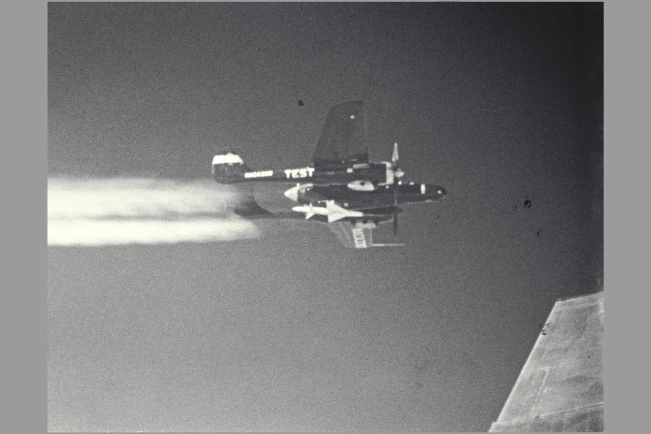
NACA Photographer (DFRC) ERF-61C-1-NO (AAF43-8330 NACA 330, NACA 111) mother ship for RECOVERABLE-BODY TECHNIQUE. Transonic Model Testing. Fig. 13 NASA SP-1998-3300 Flight Research at Ames: 57 Years of Development and Validation of Aeronautical Technology
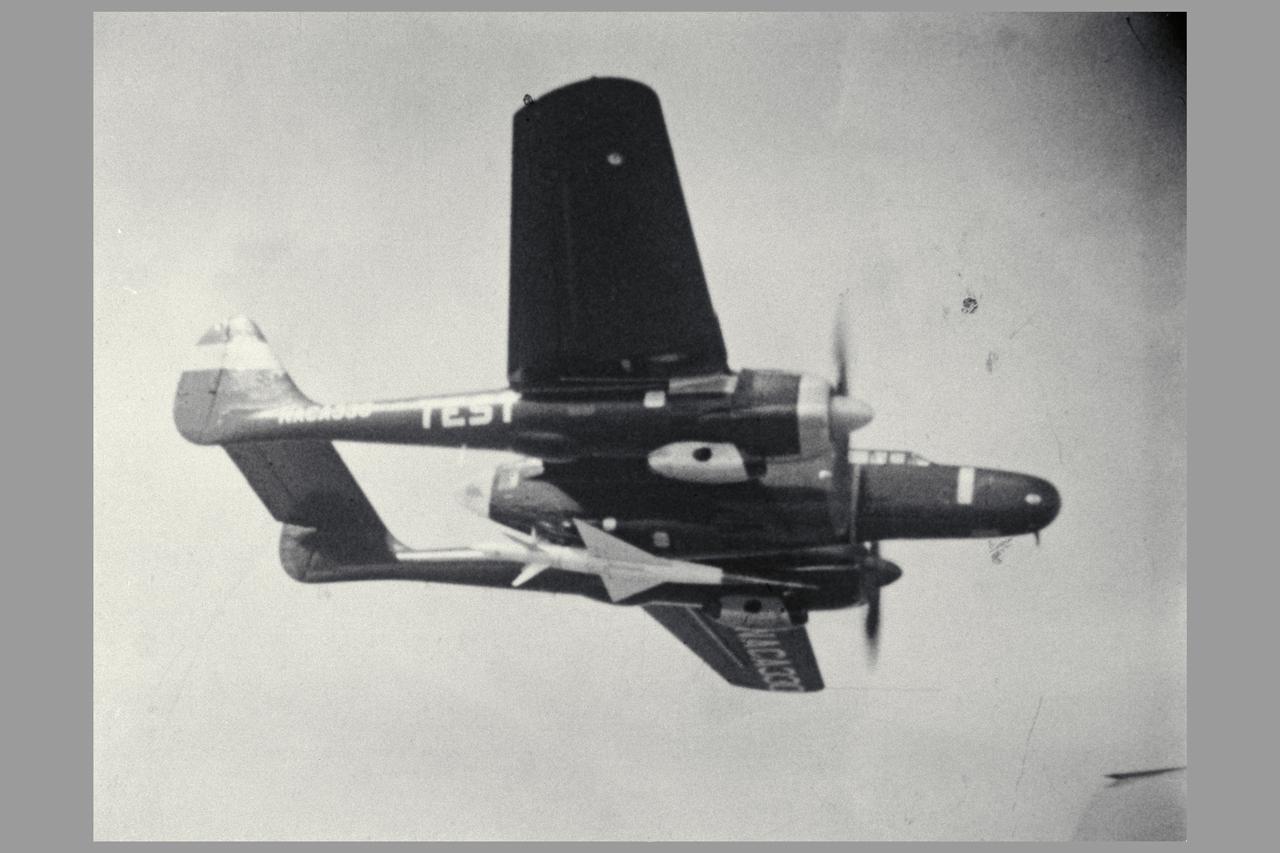
Photo by NACA 45 degree Sweptback wing model drop test Close-up of Body as it Leaves the Plane. Investigation of a Cambered and Twisted 45 degrees Swept-back Wing in the Transonic Range by the Recoverable-body Techniques.
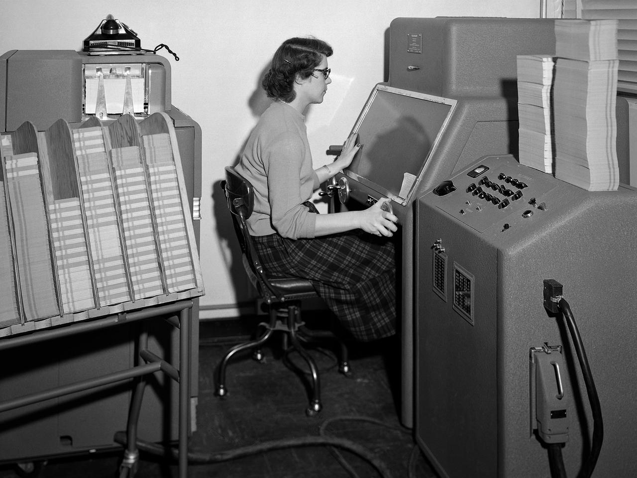
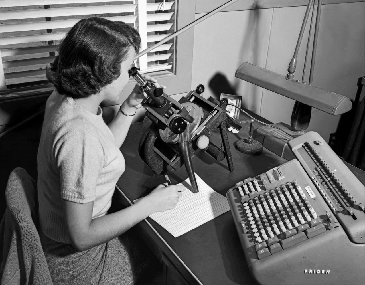
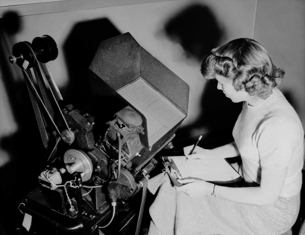
A staff member from the Computing Section at the National Advisory Committee for Aeronautics (NACA) Lewis Flight Propulsion Laboratory operates an International Business Machines (IBM) telereader at the 8- by 6-Foot Supersonic Wind Tunnel. The telereader was used to measure recorded data from motion picture film or oscillographs. The machine could perform 50 measurements per minute. The component to her right is a telerecordex that was used convert the telereader measurements into decimal form and record the data on computer punch cards. During test runs in the 8- by 6-foot tunnel, or the other large test facilities, pressure sensors on the test article were connected to mercury-filled manometer tubes located below the test section. The mercury would rise or fall in relation to the pressure fluctuations in the test section. Initially, female staff members, known as “computers,” transcribed all the measurements by hand. The process became automated with the introduction of the telereader and other data reduction equipment in the early 1950s. The Computer Section staff members were still needed to operate the machines. The Computing Section was introduced during World War II to relieve short-handed research engineers of some of the tedious work. The computers made the initial computations and plotted the data graphically. The researcher then analyzed the data and either summarized the findings in a report or made modifications or ran the test again. The computers and analysts were located in the Altitude Wind Tunnel Shop and Office Building office wing during the 1940s. They were transferred to the new facility when the 8- by 6-Foot tunnel began operations in 1948.
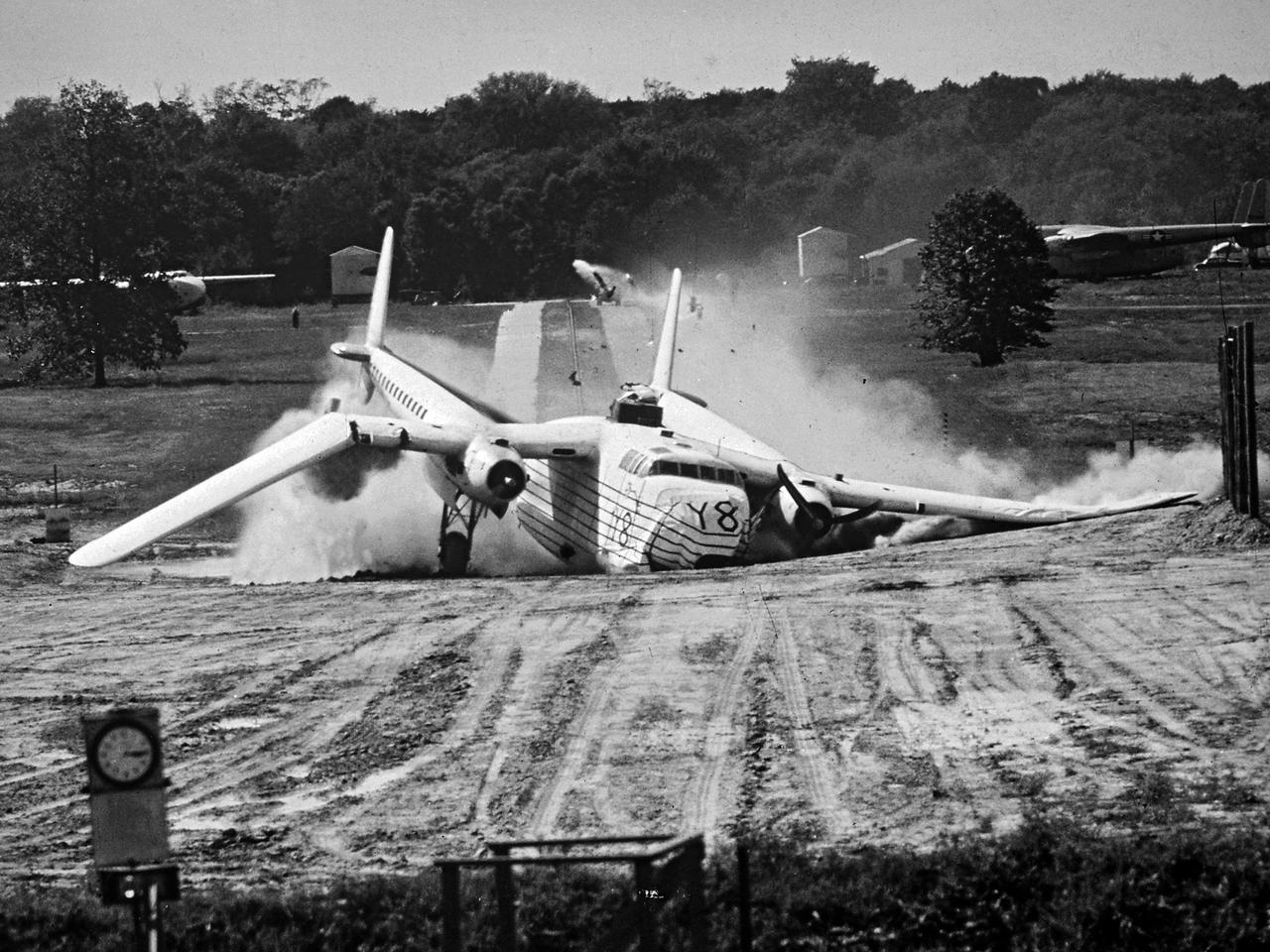
A Fairchild C-82 Packet is purposely destroyed by researchers at the National Advisory Committee for Aeronautics (NACA) Lewis Flight Propulsion Laboratory. In response to an escalating number of transport aircraft crashes in the mid-1940s, the NACA researchers undertook a decade-long investigation into a number of issues surrounding low-altitude aircraft crashes. The tests were conducted at the Ravenna Arsenal, approximately 60 miles south of the Lewis laboratory in Cleveland, Ohio. The aircraft were excess military transports from World War II. The aircraft was guided down the runway at speeds of 80 to 105 miles per hour. It came into contact with poles which tore open the 1500-gallon fuel tanks in the wings before reaching the barriers at the end of the runway. Fuel poured from the tanks and supply lines, resulting in the spread of both liquid fuel and a large cloud of spray. Solomon Weiss developed a method of dying the fuel red to improve its visibility during the crashes. This red fuel cloud trailed slightly behind the skidding aircraft, then rushed forward when the aircraft stopped. The nine-crash initial phase of testing used Lockheed C-56 Lodestar and C-82 transport aircraft to identify potential ignition sources and analyze the spread of flammable materials. The researchers were able to identify different classes of ignition sources, fuel disbursement patterns, the time when a particular ignition source might appear, rate of the fire spread, cabin survival times, and deceleration rates.
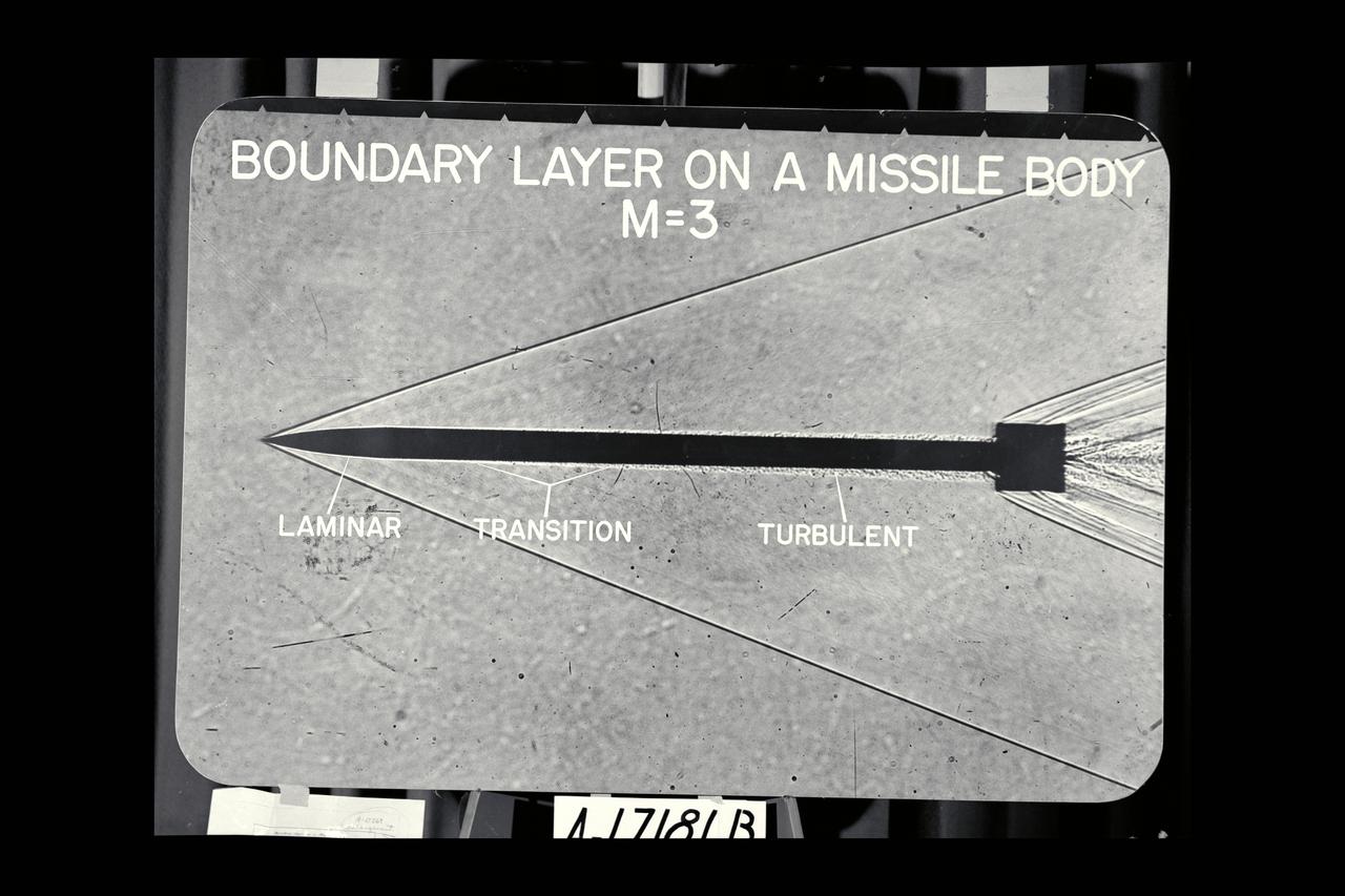
NACA Photographer Shadowgraph: Boundary Layer on Missile body @ M-3
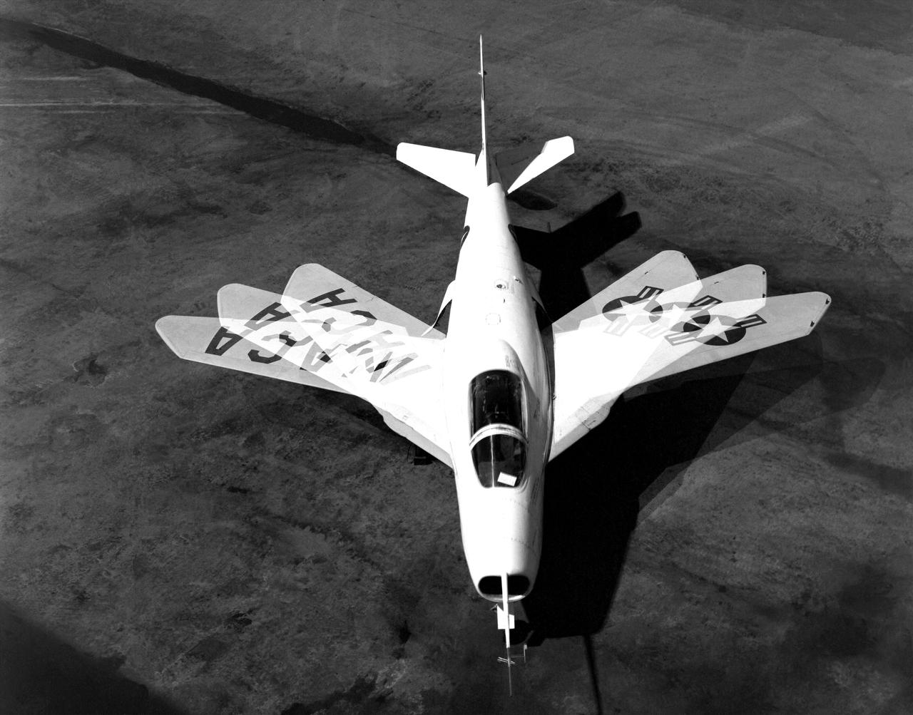
The Bell X-5 swings its wings in this multiple exposure photograph. Variable-sweep wing technology later appeared on the F-111, F-14 and B-1.
Langely Women Computer with X-4 with Friden machine. Publicity photo from Muroc California, showing female support personnel with equipment. Langley Computer with Friden machine.
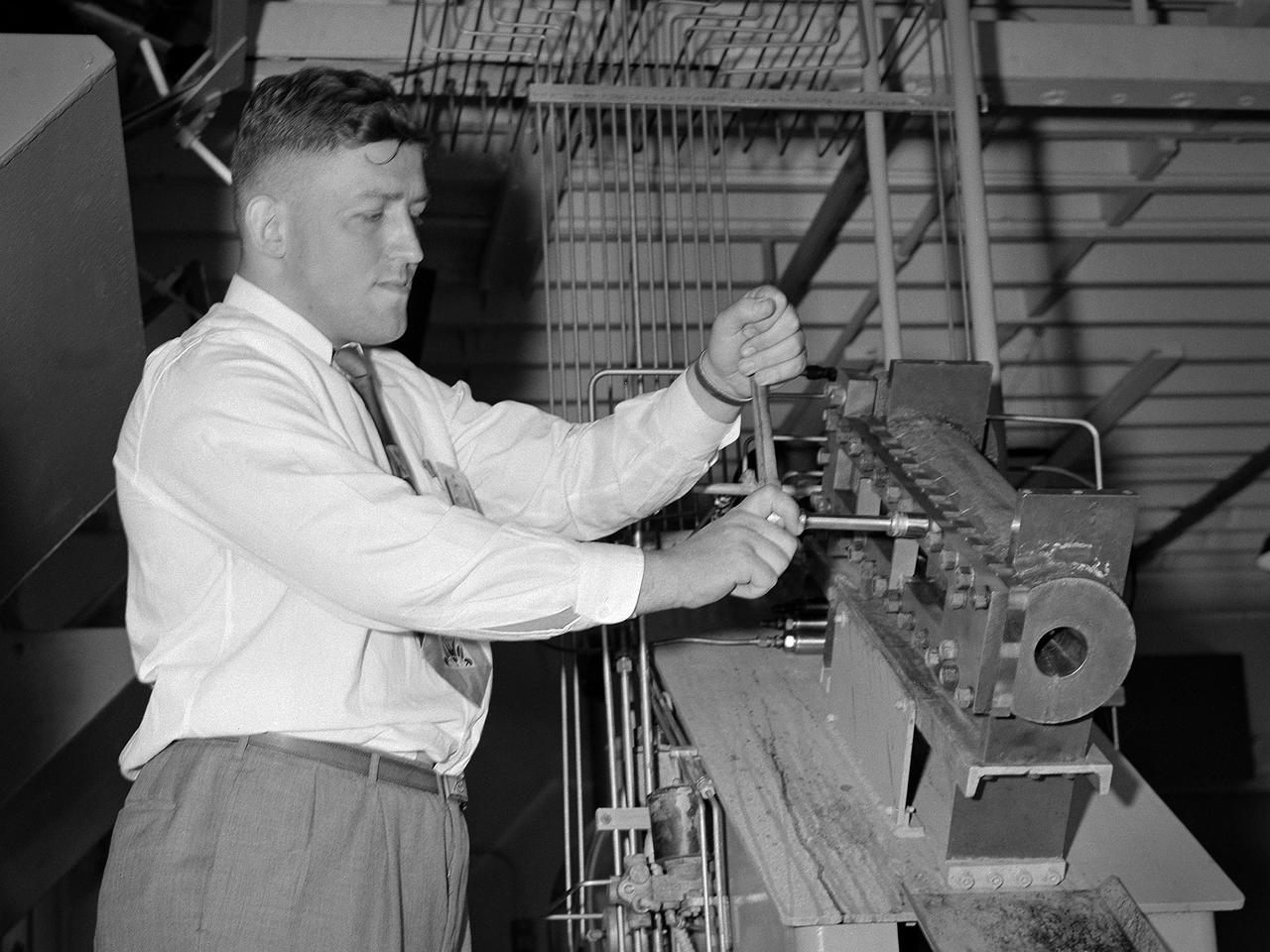
A materials researcher at the NACA’s Lewis Flight Propulsion Laboratory examines a surface crack detection apparatus in the Materials and Stresses Building during December 1952. Materials research was an important aspect of propulsion technology. Advanced engine systems relied upon alloys, and later composites, that were strong, lightweight, and impervious to high temperatures. Jet engines which became increasingly popular in the late 1940s, produced much higher temperatures than piston engines. These higher temperatures stressed engine components, particularly turbines. Although Lewis materials research began during World War II, the Materials and Thermodynamics Division was not created until 1949. Its primary laboratories were located in the Materials and Stresses Building. The group sought to create new, improved materials and to improve engine design through increased understanding of materials. The Lewis materials researchers of the 1950s made contributions to nickel-aluminum alloys, cermet blades, metal matrix composites, oxide dispersion strengthened superalloys, and universal slopes.
Publicity photo from Muroc California, showing female support personnel with equipment.
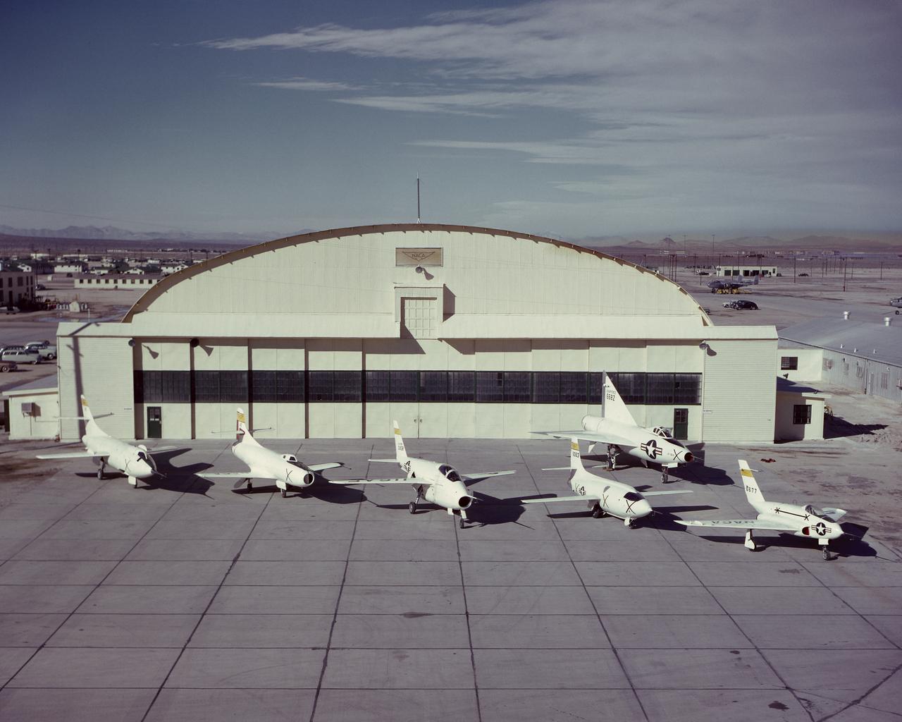
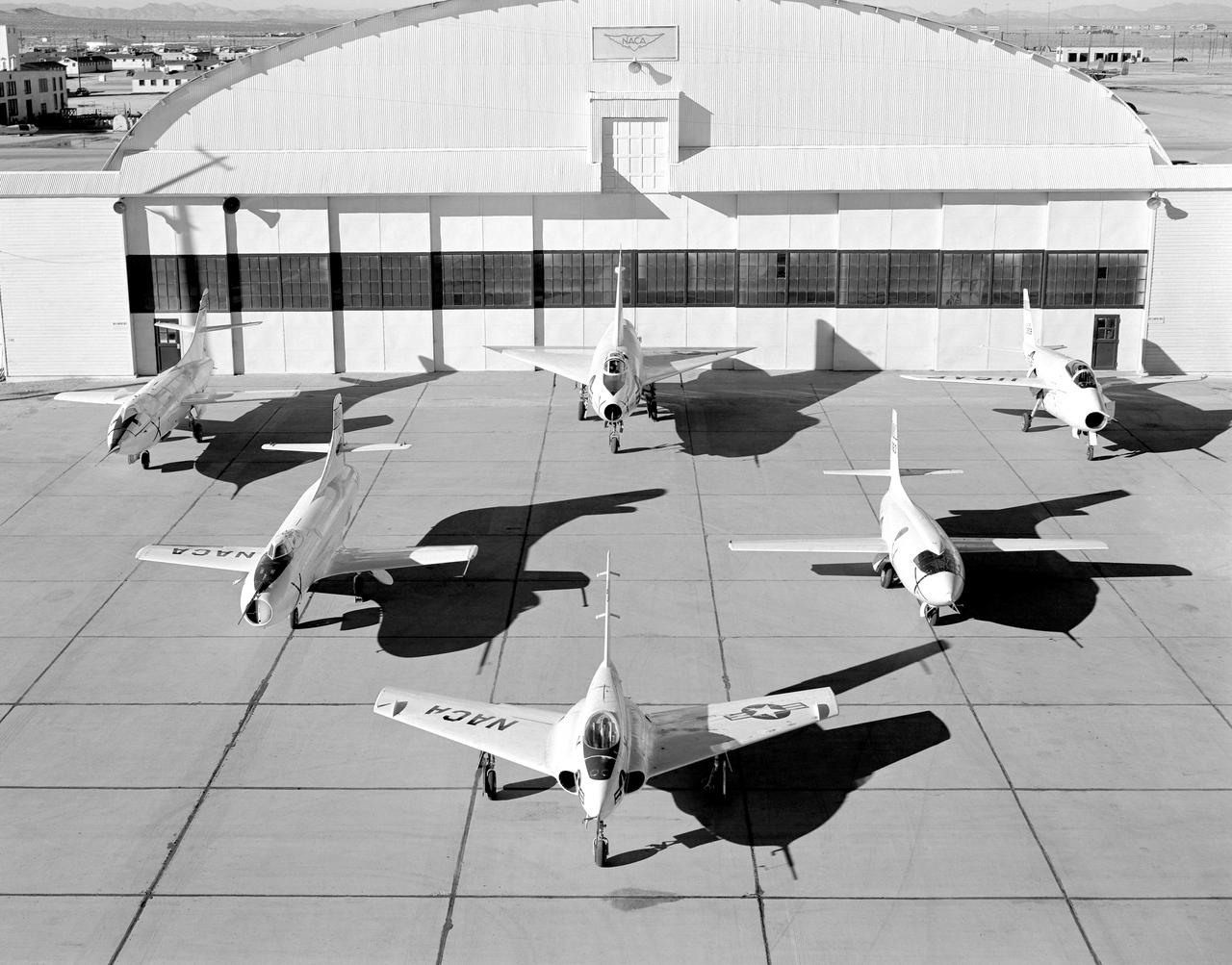
NACA X-Planes on South Base ramp. Northrop X-4, Bell X-1, Bell X-5, Douglas D-558-1, Douglas D-558-2. Back row Convair XF-92A. March 30, 1952
A researcher at the National Advisory Committee for Aeronautics (NACA) Lewis Flight Propulsion Laboratory checks the setup of a RJM-2 ramjet model in the test section of the 8- by 6-Foot Supersonic Wind Tunnel. The 8- by 6 was not only the laboratory’s first large supersonic wind tunnel, but it was also the NACA’s first facility capable of testing an operating engine at supersonic speeds. The 8- by 6-foot tunnel has been used to study engine inlets, fuel injectors, flameholders, exit nozzles, and controls on ramjet and turbojet propulsion systems. The 8-foot wide and 6-foot tall test section consisted of 1-inch thick steel plates with hatches on the floor and ceiling to facilitate the installation of the test article. The two windows seen on the right wall allowed photographic equipment to be set up. The test section was modified in 1956 to accommodate transonic research. NACA engineers drilled 4,700 holes into the test section walls to reduce transonic pressure disturbances and shock waves. NACA Lewis undertook an extensive research program on ramjets in the 1940s using several of its facilities. Ramjets provide a very simple source of propulsion. They are basically a tube which ingests high speed air, ignites it, and then expels the heated air at a significantly higher velocity. Ramjets are extremely efficient and powerful but can only operate at high speeds. Therefore, they require a booster rocket or aircraft drop to accelerate them to high speeds before they can operate.
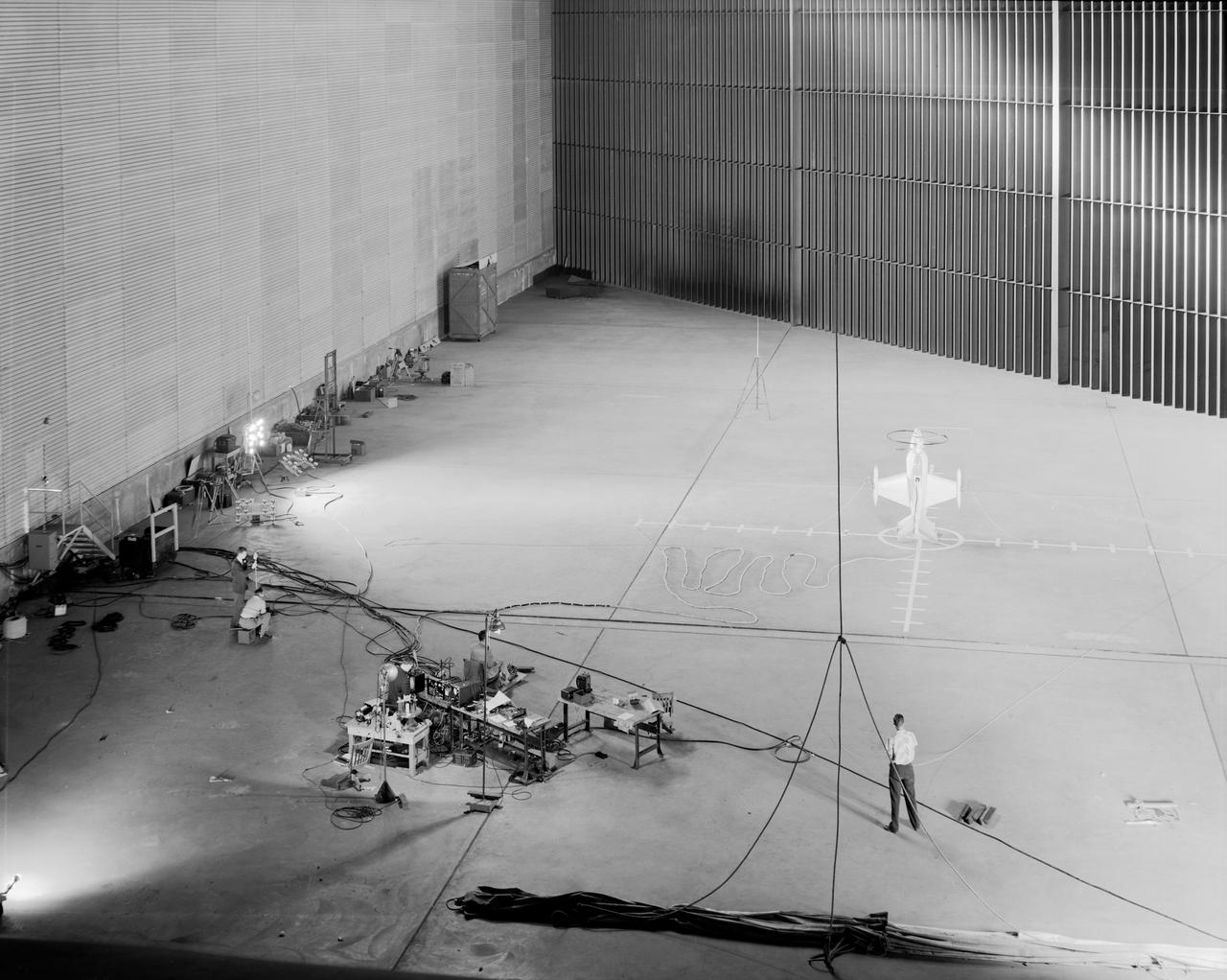
Wide shot of 40x 80 wind tunnel settling chamber with Lockheed XFV-1 model. Project engineer Mark Kelly (not shown). Remote controlled model flown in the settling chamber of the 40x80 wind tunnel. Electric motors in the model, controlled the counter-rotating propellers to test vertical takeoff. Test no. 71

electrical engineer.NACA engineer Kitty Joyner, believed to be the first NACA female engineer, as well as the first women engineer to graduate from UVA.
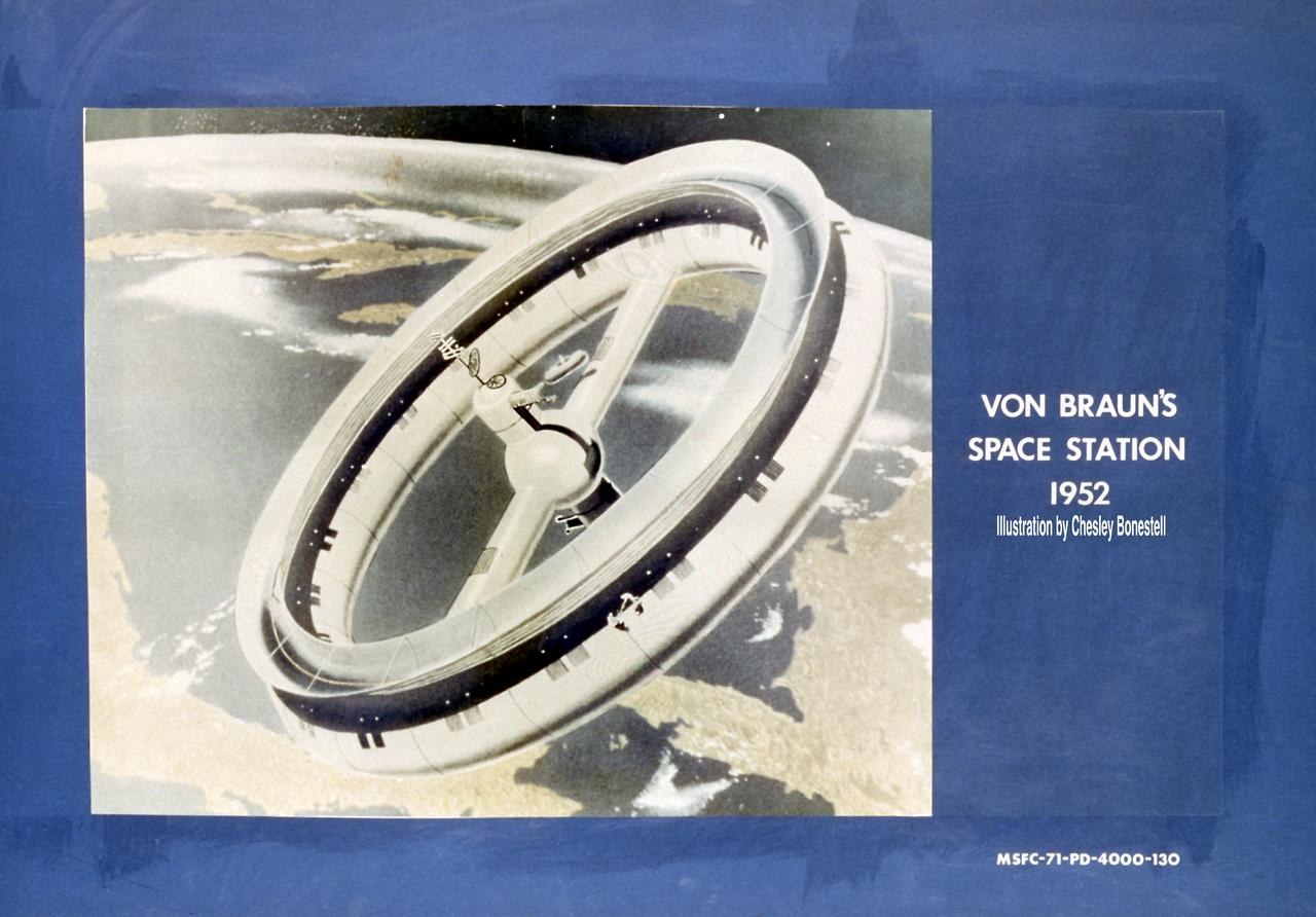
This is a von Braun 1952 space station concept. In a 1952 series of articles written in Collier's, Dr. Wernher von Braun, then Technical Director of the Army Ordnance Guided Missiles Development Group at Redstone Arsenal, wrote of a large wheel-like space station in a 1,075-mile orbit. This station, made of flexible nylon, would be carried into space by a fully reusable three-stage launch vehicle. Once in space, the station's collapsible nylon body would be inflated much like an automobile tire. The 250-foot-wide wheel would rotate to provide artificial gravity, an important consideration at the time because little was known about the effects of prolonged zero-gravity on humans. Von Braun's wheel was slated for a number of important missions: a way station for space exploration, a meteorological observatory and a navigation aid. This concept was illustrated by artist Chesley Bonestell.

Lockheed XFV-1 model. Project engineer Mark Kelly (not shown). Remote controlled model flown in the settling chamber of the 40x80 wind tunnel. Electric motors in the model, controlled the counter-rotating propellers to test vertical takeoff. Test no. 71

A Wright Aeronautical XRJ47-W-5 ramjet installed in a test chamber of the National Advisory Committee for Aeronautics’ (NACA) new Propulsion Systems Laboratory at the Lewis Flight Propulsion Laboratory. Construction of the facility had only recently been completed, and NACA engineers were still testing the various operating systems. The Propulsion Systems Laboratory was the NACA’s most powerful facility for testing full-scale engines in simulated flight altitudes. It contained two 14-foot diameter and 100-foot-long altitude chambers that ran parallel to one another with a control room in between. The engine being tested was installed inside the test section of one of the chambers, seen in this photograph. Extensive instrumentation was fitted onto the engine prior to the test. Once the chamber was sealed, the altitude conditions were introduced, and the engine was ignited. Operators in the control room could run the engine at the various speeds and adjust the altitude conditions to the desired levels. The engine’s exhaust was ejected into the cooling equipment. Two 48-inch diameter XRJ47-W-5 ramjets were used to power the North American Aviation Navaho Missile. The Navaho was a winged missile that was intended to travel up to 3000 miles carrying a nuclear warhead. It was launched using rocket booster engines that were ejected after the missile’s ramjet engines were ignited.
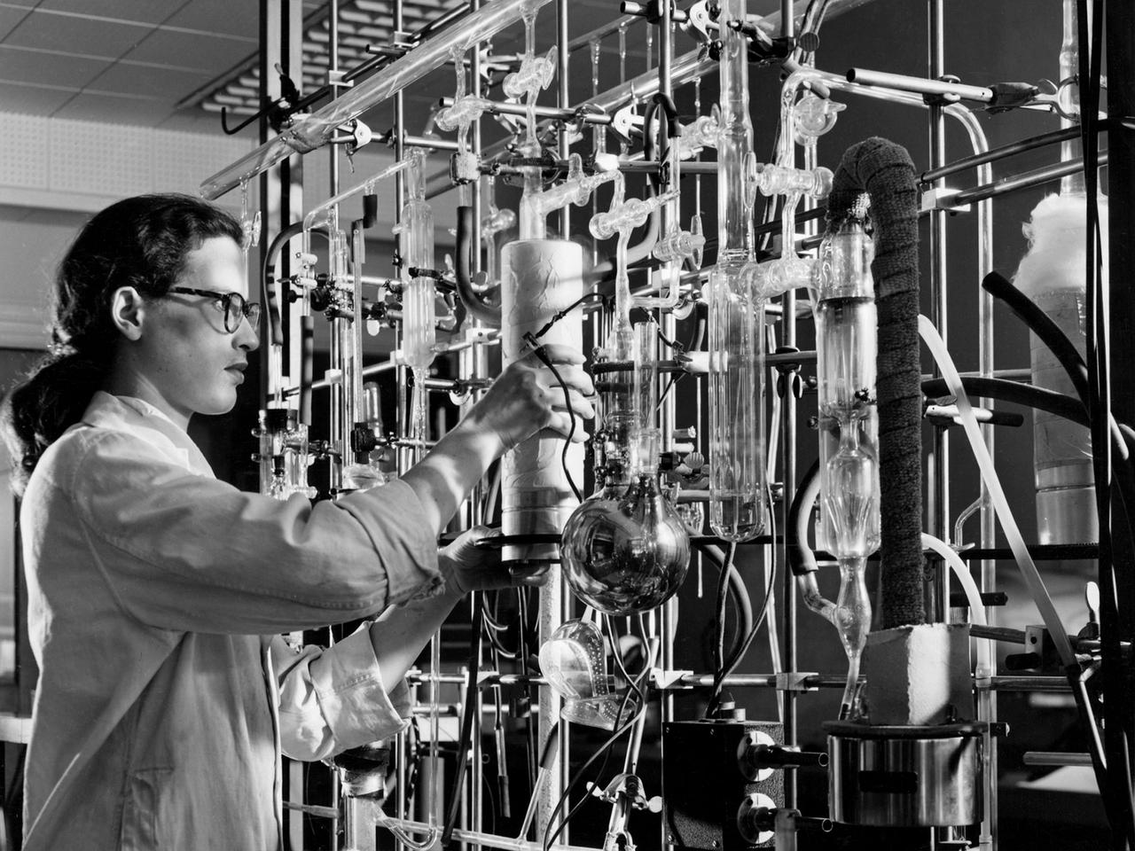
William Kerslake, a combustion researcher at the National Advisory Committee for Aeronautics (NACA) Lewis Flight Propulsion Laboratory, examines the setup of a transparent rocket in a Rocket Laboratory test cell. Kerslake joined NACA Lewis the previous summer after graduating from the Case Institute of Technology with a chemistry degree. His earliest professional research concentrated on combustion instability in small rocket engines. While at Case the quiet, 250-pound Kerslake also demonstrated his athletic prowess on the wrestling team. He continued wrestling for roughly a decade afterwards while conducting his research with the NACA. Kerslake participated in Olympic competitions in Helsinki (1952), Melbourne (1956), and Rome (1960). He won 30 national championships in three different weight classes and captured the gold at the 1955 Pan American Games in Mexico City. Kerslake accomplished all this while maintaining his research career, raising a family, and paying his own expenses. As his wrestling career was winding down in the early 1960s, Kerslake’s professional career changed, as well. He was transferred to Harold Kaufman’s Electrostatic Propulsion Systems Section in the new Electromagnetic Propulsion Division. Kaufman was developing the first successful ion engine at the time, and Kerslake spent the remainder of his career working in the electric propulsion field. He was heavily involved in the two Space Electric Rocket Test (SERT) missions which demonstrated that the ion thrusters could successfully operate in space. Kerslake retired in 1985 with over 30 years of service.
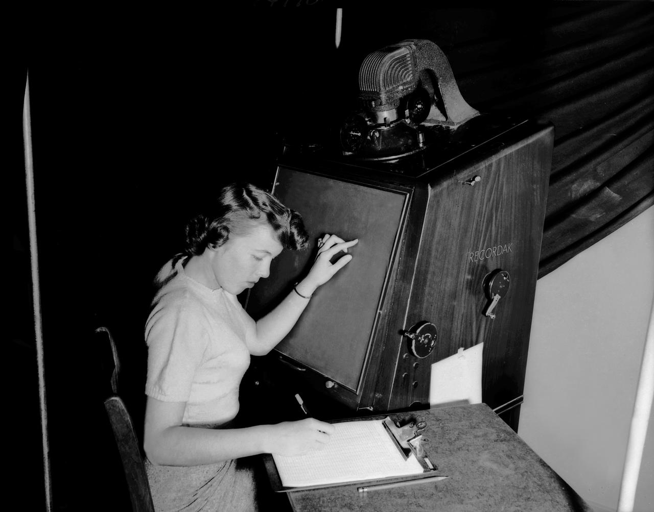
Publicity photo from Muroc California, showing female support personnel with equipment. A women working on a Kodak Recordak microfilm reader.

One of the two primary coolers at the Propulsion Systems Laboratory at the National Advisory Committee for Aeronautics (NACA) Lewis Flight Propulsion Laboratory. Engines could be run in simulated altitude conditions inside the facility’s two 14-foot-diameter and 24-foot-long test chambers. The Propulsion Systems Laboratory was the nation’s only facility that could run large full-size engine systems in controlled altitude conditions. At the time of this photograph, construction of the facility had recently been completed. Although not a wind tunnel, the Propulsion Systems Laboratory generated high-speed airflow through the interior of the engine. The air flow was pushed through the system by large compressors, adjusted by heating or refrigerating equipment, and de-moisturized by air dryers. The exhaust system served two roles: reducing the density of the air in the test chambers to simulate high altitudes and removing hot gases exhausted by the engines being tested. It was necessary to reduce the temperature of the extremely hot engine exhaust before the air reached the exhauster equipment. As the air flow exited through exhaust section of the test chamber, it entered into the giant primary cooler seen in this photograph. Narrow fins or vanes inside the cooler were filled with water. As the air flow passed between the vanes, its heat was transferred to the cooling water. The cooling water was cycled out of the system, carrying with it much of the exhaust heat.
NACA High Speed Flight Station aircraft at South Base. Clockwise from far left: D-558-II, XF-92A, X-5, X-1, X-4, and D-558-I.
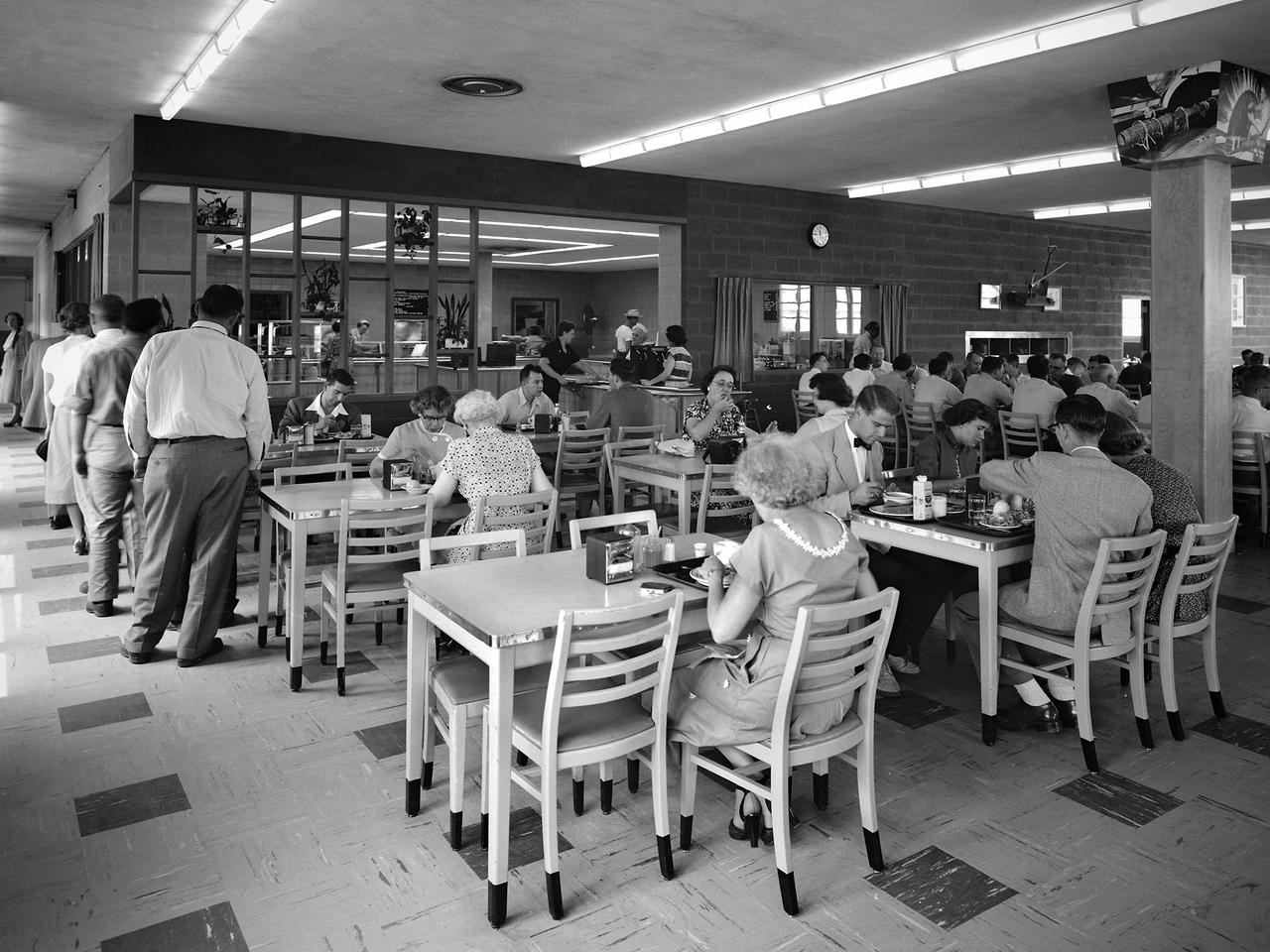
NACA staff members queue up in the Lewis Flight Propulsion Laboratory cafeteria in August 1952. The cafeteria originally opened in November 1942 inside the south end of the Engine Research Building. A non-profit Exchange was established to handle the finances, while Helen Thompson, a German born pastry cook, ran the day-to-day operations. Employees could also purchase her bakery to take home with them. Services were expanded to include a lunch counter and a food cart that ferried meals to the facilities. By the end of World War II the cafeteria was serving nearly 1600 meals daily in a space designed for half of that. In 1951 a new wing was added to the Utilities Building to accommodate an expanded cafeteria, seen in this photograph. In the mid-1960s an auxiliary unit was built in the new Development Engineering Building located across Brookpark Road.