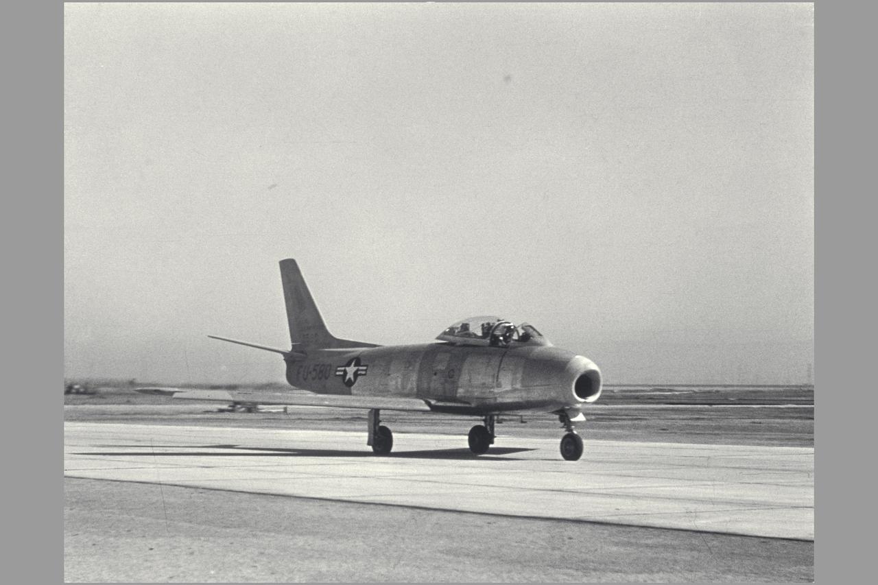
F-86E (AF 50-580). Gunsight Tracking and Guidance and Control Displays. Note: Used in publication in Flight Research at Ames; 57 Years of Development and Validation of Aeronautical Technology NASA SP-1998-3300 fig 78
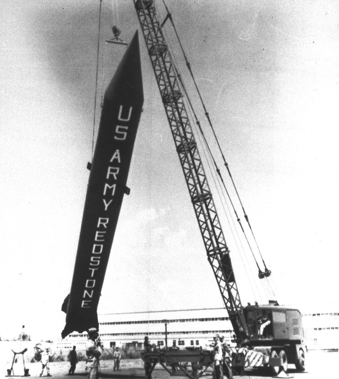
U.S. Army Redstone Rocket: The Redstone ballistic missile was a high-accuracy, liquid-propelled, surface-to-surface missile developed by the Army Ballistic Missile Agency, Redstone Arsenal, in Huntsville, Alabama, under the direction of Dr. von Braun. The Redstone rocket was also known as "Old Reliable" because of its many diverse missions. The first Redstone Missile was launched from Cape Canaveral, Florida on August 30, 1953.
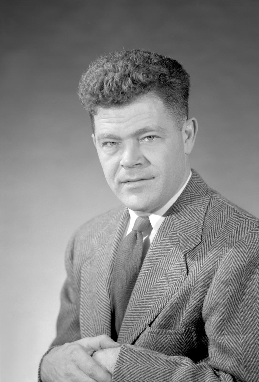
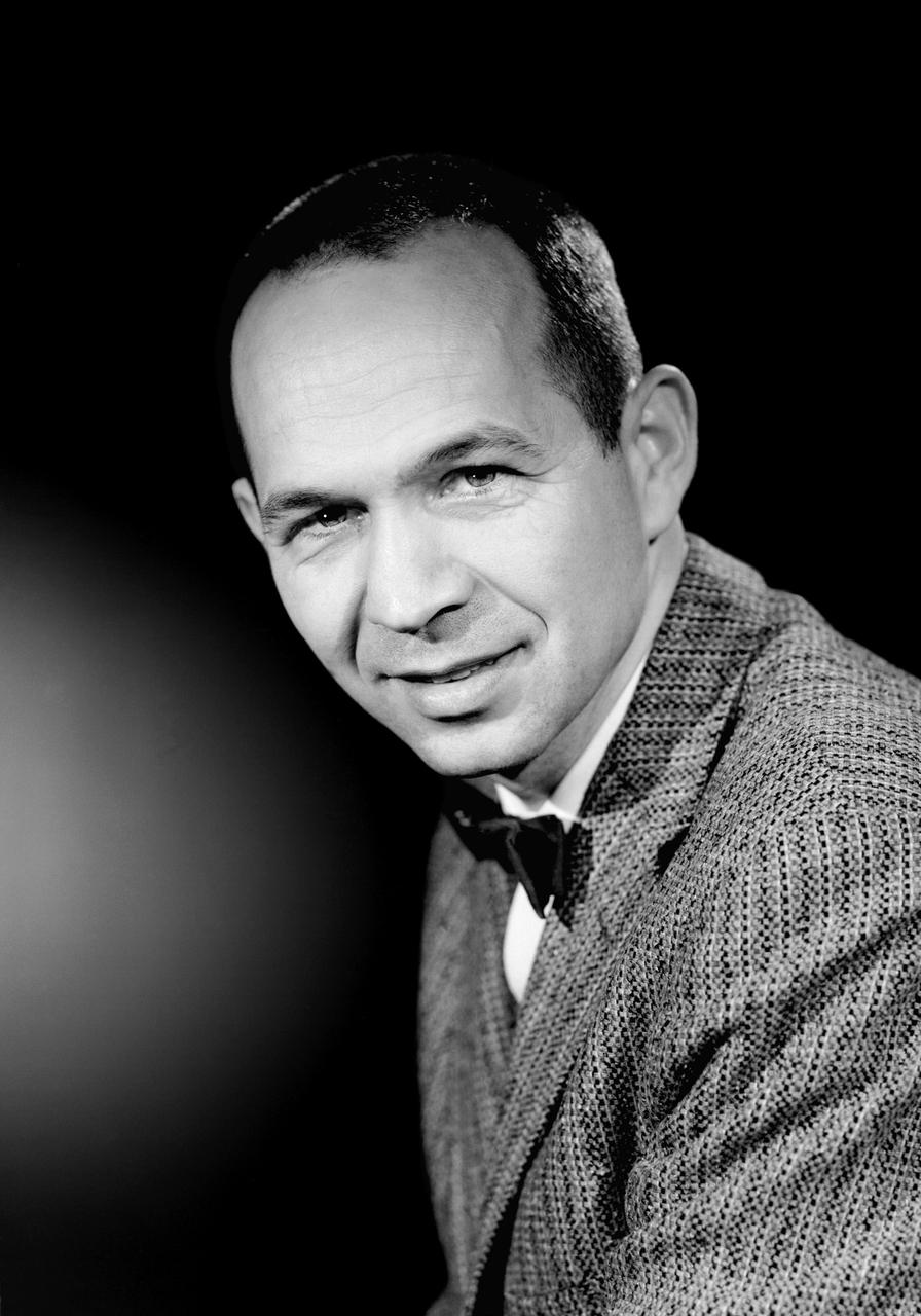
Portrait of Author W. Vogeley
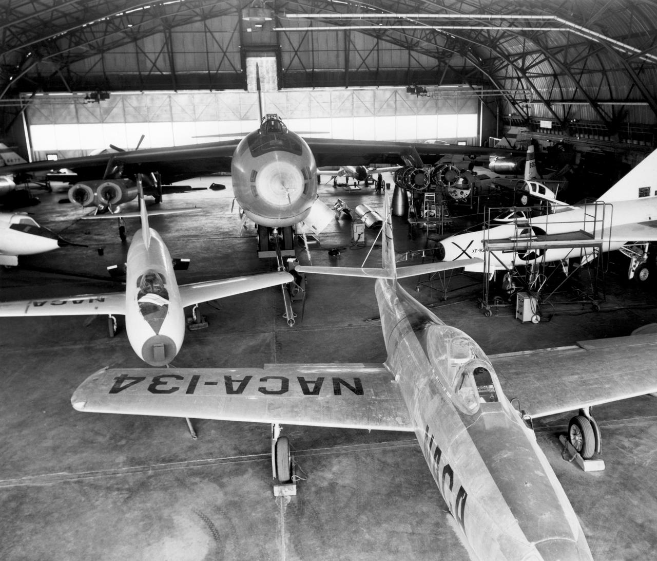
In the center foreground of this 1953 hangar photo is the YF-84A (NACA 134/Air Force 45-59490) used for vortex generator research. It arrived on November 28, 1949, and departed on April 21, 1954. Beside it is the third D-558-1 aircraft (NACA 142/Navy 37972). This aircraft was used for a total of 78 transonic research flights from April 1949 to June 1954. It replaced the second D-558-1, lost in the crash which killed Howard Lilly. Just visible on the left edge is the nose of the first D-558-2 (NACA 143/Navy 37973). Douglas turned the aircraft over to NACA on August 31, 1951, after the contractor had completed its initial test flights. NACA only made a single flight with the aircraft, on September 17, 1956, before the program was cancelled. In the center of the photo is the B-47A (NACA 150/Air Force 49-1900). The B-47 jet bomber, with its thin, swept-back wings, and six podded engines, represented the state of the art in aircraft design in the early 1950s. The aircraft undertook a number of research activities between May 1953 and its 78th and final research flight on November 22, 1957. The tests showed that the aircraft had a buffeting problem at speeds above Mach 0.8. Among the pilots who flew the B-47 were later X-15 pilots Joe Walker, A. Scott Crossfield, John B. McKay, and Neil A. Armstrong. On the right side of the B-47 is NACA's X-1 (Air Force 46-063). The second XS-1 aircraft built, it was fitted with a thicker wing than that on the first aircraft, which had exceeded Mach 1 on October 14, 1947. Flight research by NACA pilots indicated that this thicker wing produced 30 percent more drag at transonic speeds compared to the thinner wing on the first X-1. After a final flight on October 23, 1951, the aircraft was grounded due to the possibility of fatigue failure of the nitrogen spheres used to pressurize the fuel tanks. At the time of this photo, in 1953, the aircraft was in storage. In 1955, the aircraft was extensively modified, becoming the X-1E. In front o
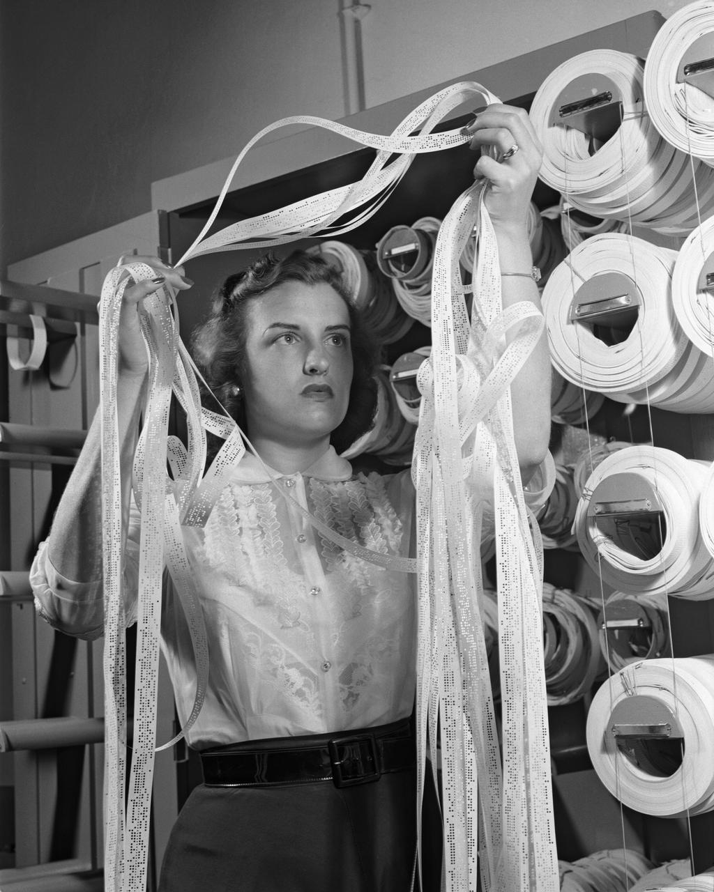
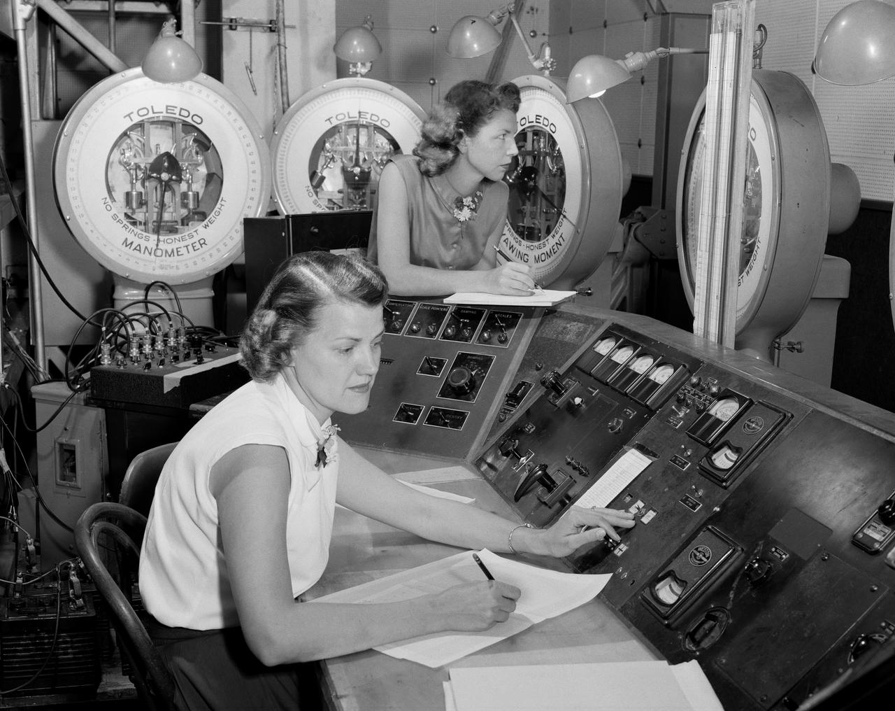
Women Adequately Filling Posts In NACA Laboratory: Mrs. Doris Rudd Porter Baron handling Manometertape, Bell computer.
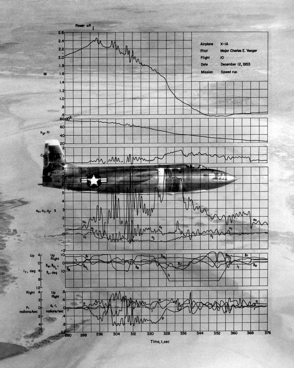
This photo of the X-1A includes graphs of the flight data from Maj. Charles E. Yeager's Mach 2.44 flight on December 12, 1953. (This was only a few days short of the 50th anniversary of the Wright brothers' first powered flight.) After reaching Mach 2.44, then the highest speed ever reached by a piloted aircraft, the X-1A tumbled completely out of control. The motions were so violent that Yeager cracked the plastic canopy with his helmet. He finally recovered from a inverted spin and landed on Rogers Dry Lakebed. Among the data shown are Mach number and altitude (the two top graphs). The speed and altitude changes due to the tumble are visible as jagged lines. The third graph from the bottom shows the G-forces on the airplane. During the tumble, these twice reached 8 Gs or 8 times the normal pull of gravity at sea level. (At these G forces, a 200-pound human would, in effect, weigh 1,600 pounds if a scale were placed under him in the direction of the force vector.) Producing these graphs was a slow, difficult process. The raw data from on-board instrumentation recorded on oscillograph film. Human computers then reduced the data and recorded it on data sheets, correcting for such factors as temperature and instrument errors. They used adding machines or slide rules for their calculations, pocket calculators being 20 years in the future.
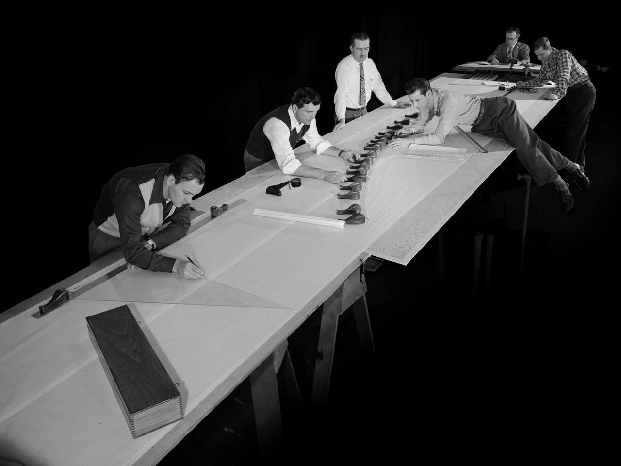
Draftsmen in the Materials and Stresses Building at the National Advisory Committee for Aeronautics (NACA) Lewis Flight Propulsion Laboratory create a template for a compressor using actual compressor blades. The Compressor and Turbine Division contained four sections of researchers dedicated to creating better engine components. The Materials and Thermodynamics Division studied the strength, durability, heat transfer characteristics, and physical composition of various materials. The two divisions were important to the research and development of new aircraft engines. The constant battle to increase the engine’s thrust while decreasing its overall weight resulted in additional stress on jet engine components, particularly compressors. As speed and maneuverability were enhanced, the strain on the engines and inlets grew. For decades NACA Lewis researchers continually sought to improve compressor blade design, develop stronger composite materials, and minimize flutter and inlet distortions.
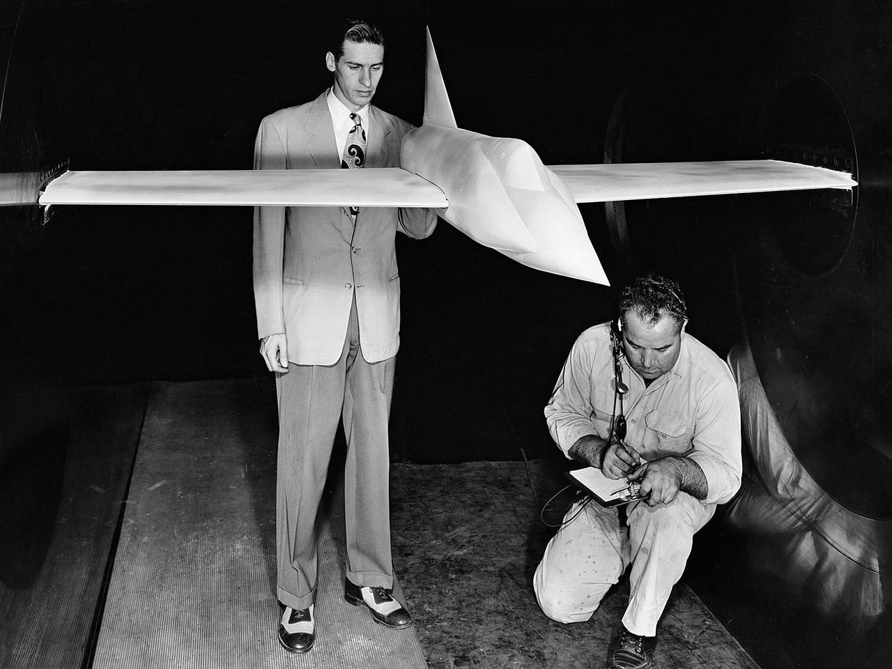
A .10-scale model of Convair’s XF-102 in the 8- by 6-Foot Supersonic Wind Tunnel at the National Advisory Committee for Aeronautics (NACA) Lewis Flight Propulsion Laboratory for jet exit studies. The XF-102 was a prototype of the F-102 Delta Dagger. The F-102 served as an interceptor against long range bombers from the Soviet Union. The aircraft was powered by a Pratt and Whitney J57 turbojet. The first prototype crashed two weeks after is first flight on October 24, 1953, just months after this photograph. Engineers then incorporated the fixed-wing design to reduce drag at supersonic speeds. The production model F-102 became the first delta-wing supersonic aircraft in operation. The 8- by 6-Foot Supersonic Wind Tunnel is used to study propulsion systems, including inlets and exit nozzles, combustion fuel injectors, flame holders, exit nozzles, and controls on ramjet and turbojet engines. Flexible sidewalls alter the tunnel’s nozzle shape to vary the Mach number during operation. A seven-stage axial compressor, driven by three electric motors that yield a total of 87,000 horsepower, generates air speeds from Mach 0.36 to 2.0.
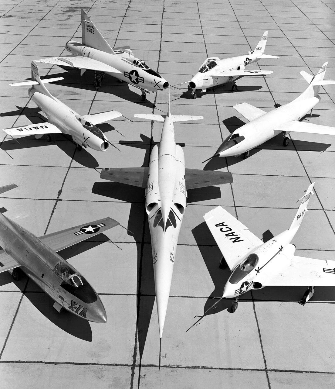
X-3 (center), and clockwise from left: X-1A, D-558-I, XF-92A, X-5, D-558-II, and X-4.
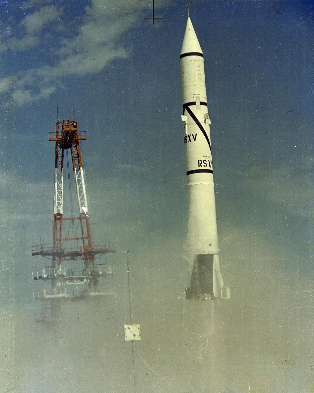
The first Redstone was fired at Cape Canaveral, Florida on August 20, 1953. Redstone was the first major rocket development program for United States by the Peenemuende group led by Dr. Wernher von Braun. The Redstone launch photographed here, from November 17, 1954, was the fifth launch of a Redstone rocket.
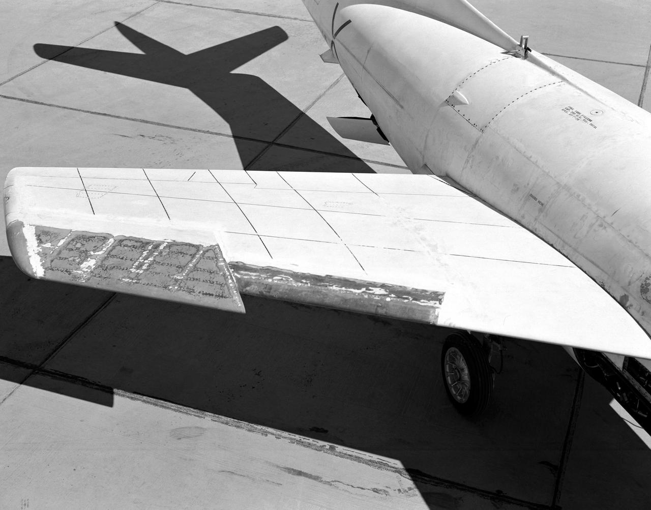
Wing chord extension on D-558-2
Women Workers at NACA
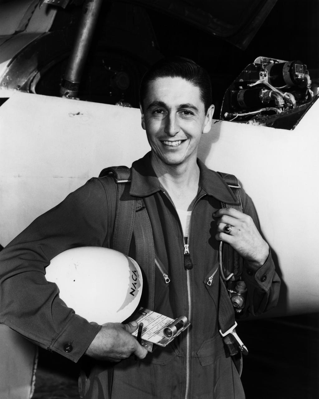
L59-1497-6 Maxime A. Faget was born in British Honduras in 1921, the son of an honored physician of the U.S. Public Health Service. In 1943 he earned a B.S. in mechanical engineering from Louisiana State University. After service as a navy submarine officer, he joined the Langley staff in 1946 as a member of the Pilotless Aircraft Research Division. His early work for PARD involved the invention of choking inlets for ramjets and a flight Mach meter. Photograph published in Engineer in Charge: A History of the Langley Aeronautical Laboratory, 1917-1958 by James R. Hansen. Page 379.
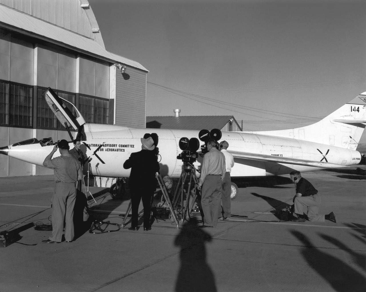
Scott Crossfield talks to newsmen in front of NACA South Base hangar after his first flight to Mach 2 in the Douglas D-558-2.
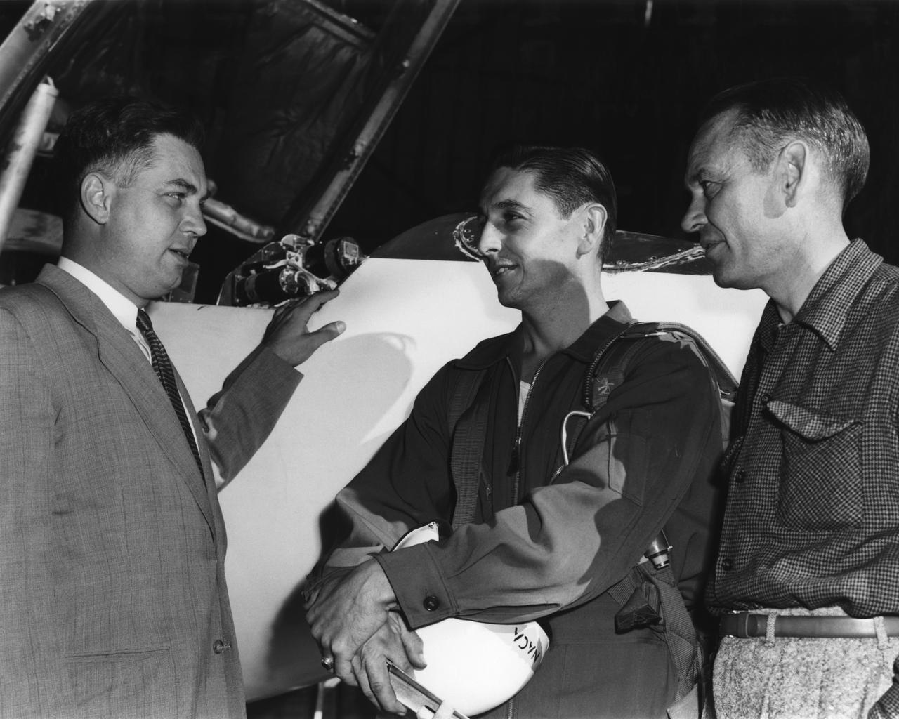
High-Speed Research Station Director Walter C. Williams, NACA pilot A. Scott Crossfield, and Director of Flight Operations Joe Vensel in front of the Douglas D-558-2 after the first Mach 2 flight.
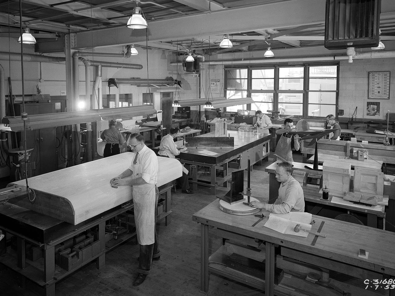
Craftsmen work in the wood model shop at the National Advisory Committee for Aeronautics (NACA) Lewis Flight Propulsion Laboratory. The Fabrication Division created almost all of the equipment and models used at the laboratory. The Fabrication Shop building contained a number of specialized shops in the 1940s and 1950s. These included a Machine Shop, Sheet Metal Shop, Wood Model and Pattern Shop, Instrument Shop, Thermocouple Shop, Heat Treating Shop, Metallurgical Laboratory, and Fabrication Office. The Wood Model and Pattern Shop created everything from control panels and cabinets to aircraft models molds for sheet metal work.
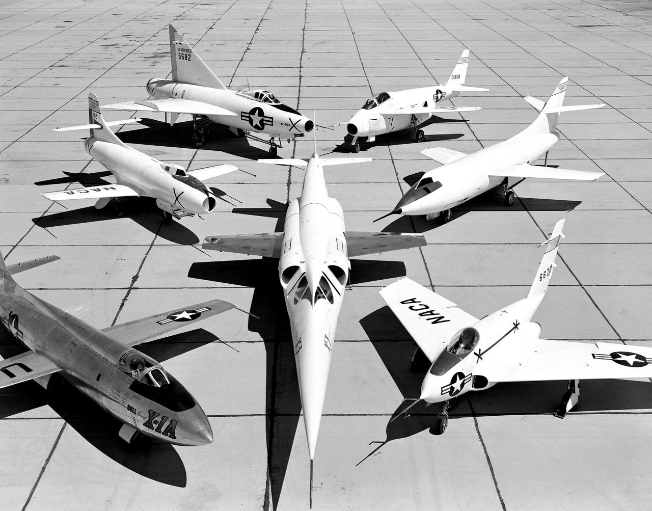
X-3 (center), and clockwise from left: X-1A, D-558-I, XF-92A, X-5, D-558-II, and X-4.
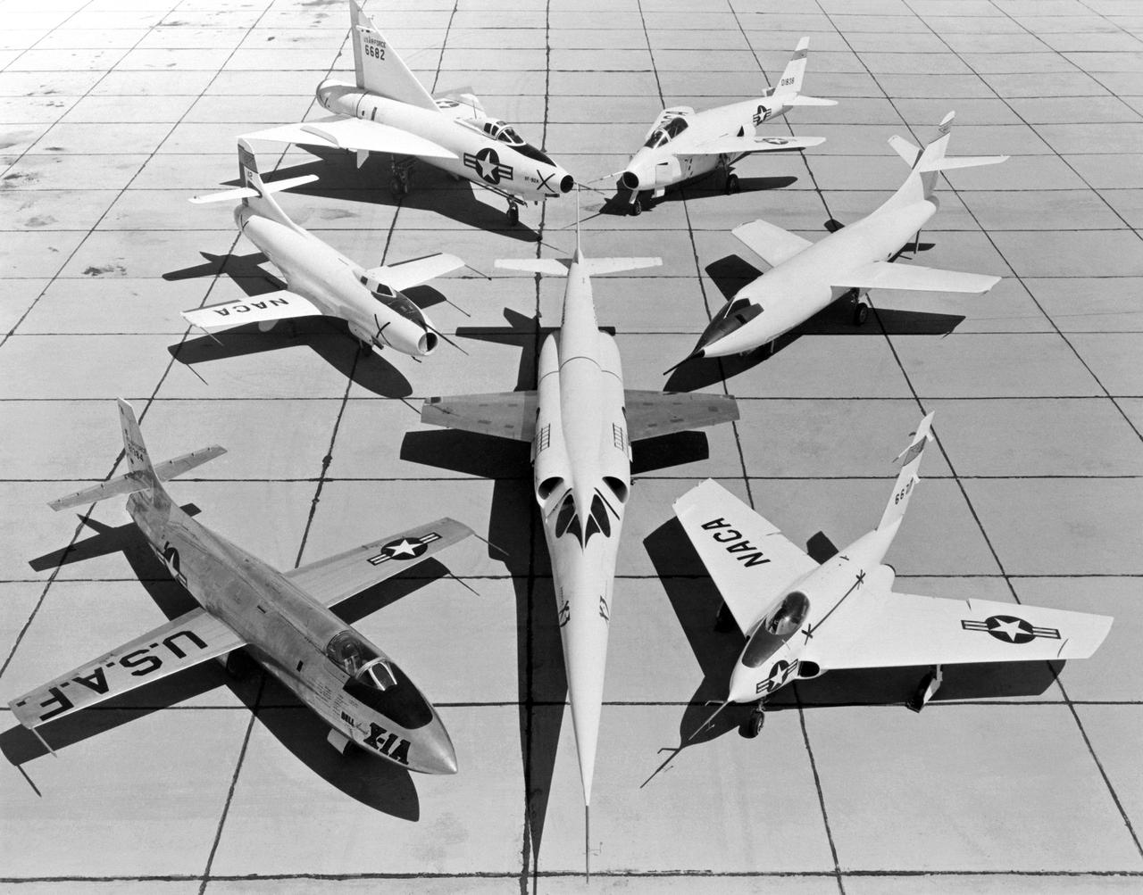
A 1953 photo of some of the research aircraft at the NACA High-Speed Flight Research Station (now known as the the Dryden Flight Research Center). The photo shows the X-3 (center) and, clockwise from left: X-1A (Air Force serial number 48-1384), the third D-558-1 (NACA tail number 142), XF-92A, X-5, D-558-2, and X-4.
NACA pilot A. Scott Crossfield next to the D-558-2 after first Mach 2 flight.
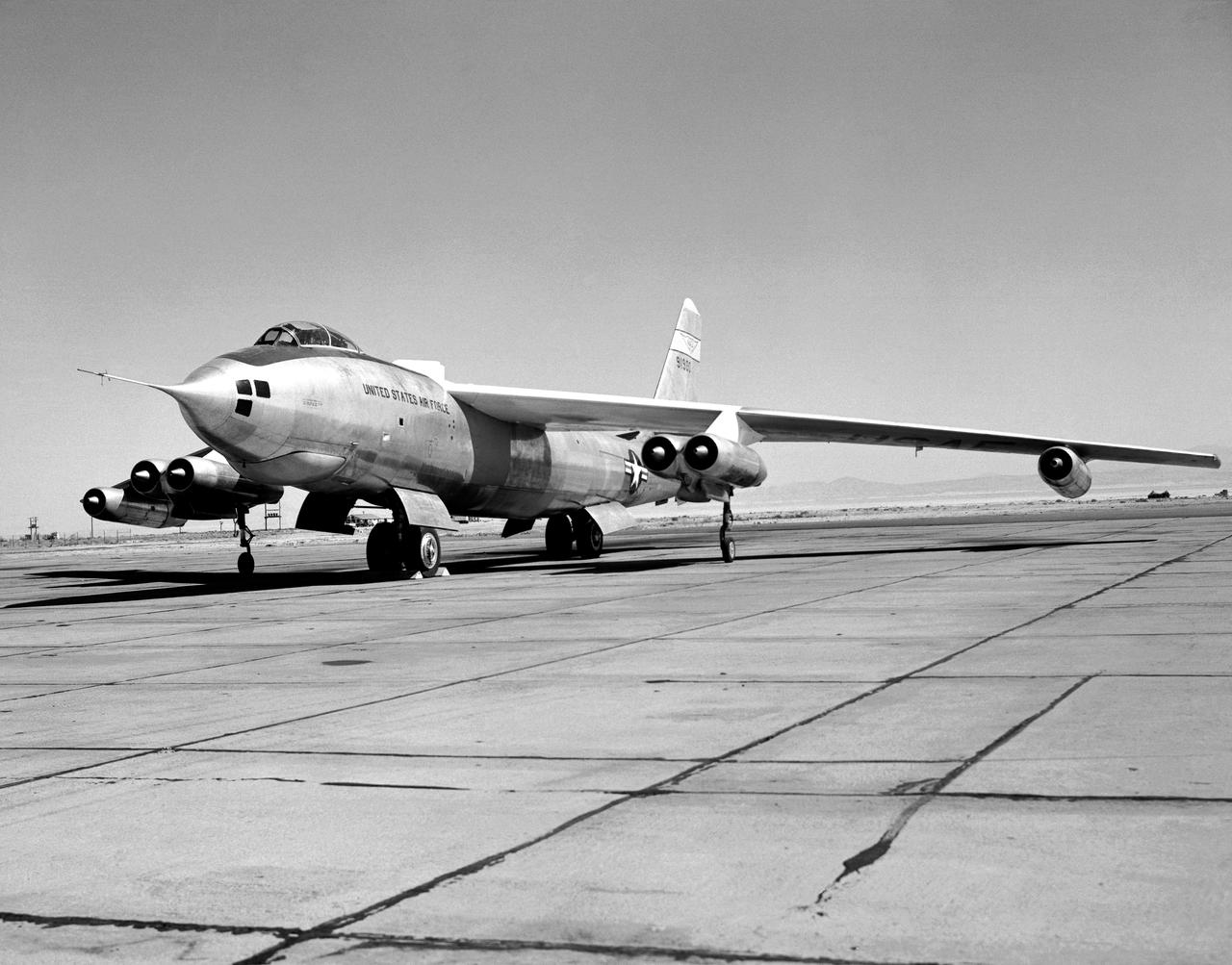
B-47A on ramp
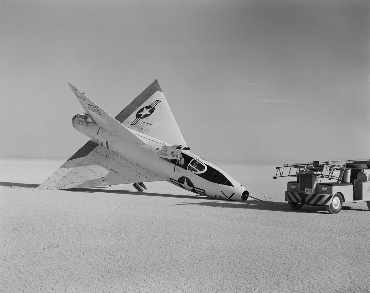
The XF-92A, which had a minor landing mishap in 1953, was the concept for the first delta wing fighter in the U.S. inventory, the F-102.
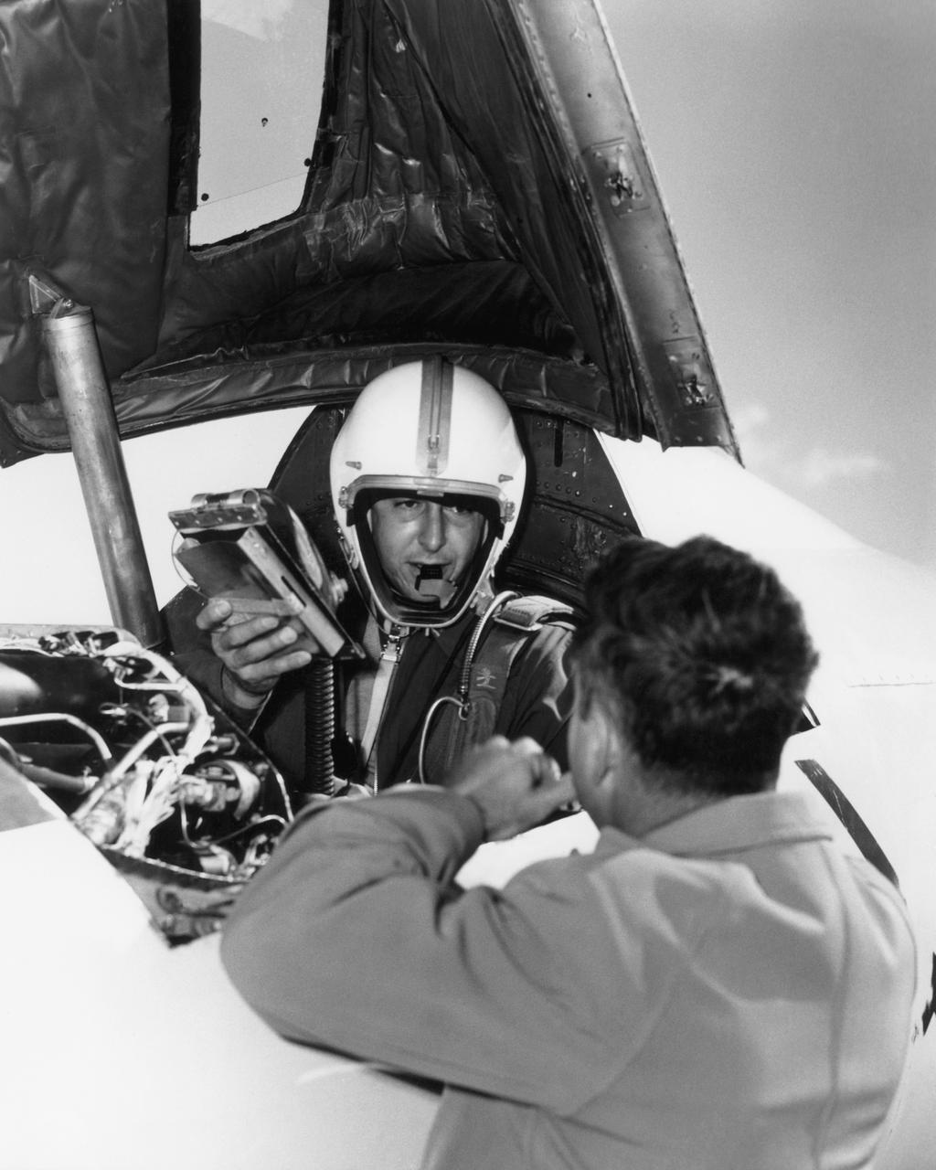
Scott Crossfield in cockpit of the Douglas D-558-2 after first Mach 2 flight.
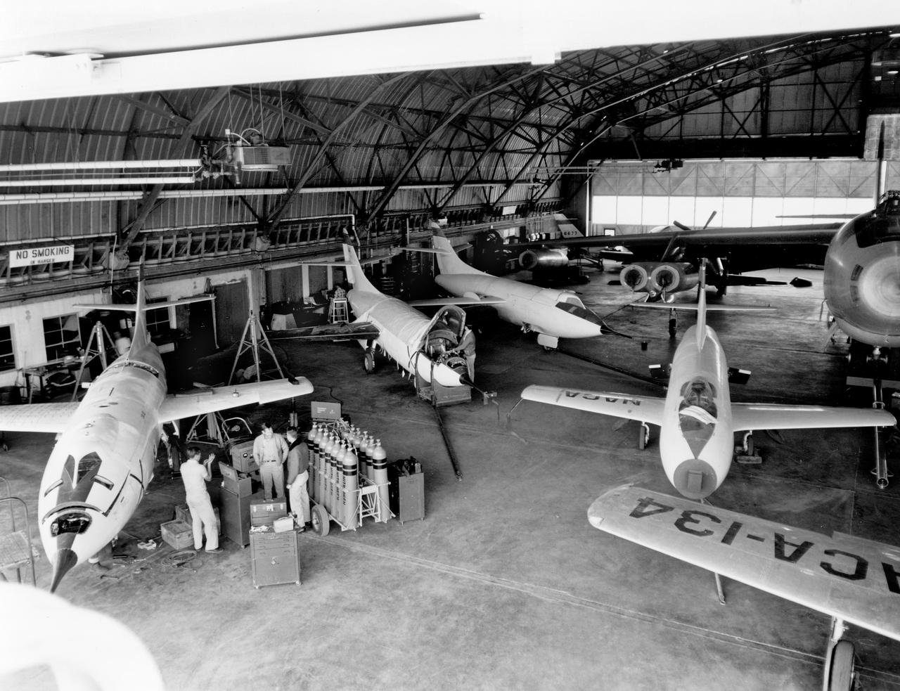
The aircraft in this 1953 photo of the National Advisory Committee for Aeronautics (NACA) hangar at South Base of Edwards Air Force Base showed the wide range of research activities being undertaken. On the left side of the hangar are the three D-558-2 research aircraft. These were designed to test swept wings at supersonic speeds approaching Mach 2. The front D-558-2 is the third built (NACA 145/Navy 37975). It has been modified with a leading-edge chord extension. This was one of a number of wing modifications, using different configurations of slats and/or wing fences, to ease the airplane's tendency to pitch-up. NACA 145 had both a jet and a rocket engine. The middle aircraft is NACA 144 (Navy 37974), the second built. It was all-rocket powered, and Scott Crossfield made the first Mach 2 flight in this aircraft on November 20, 1953. The aircraft in the back is D-558-2 number 1. NACA 143 (Navy 37973) was also carried both a jet and a rocket engine in 1953. It had been used for the Douglas contractor flights, then was turned over to the NACA. The aircraft was not converted to all-rocket power until June 1954. It made only a single NACA flight before NACA's D-558-2 program ended in 1956. Beside the three D-558-2s is the third D-558-1. Unlike the supersonic D-558-2s, it was designed for flight research at transonic speeds, up to Mach 1. The D-558-1 was jet-powered, and took off from the ground. The D-558-1's handling was poor as it approached Mach 1. Given the designation NACA 142 (Navy 37972), it made a total of 78 research flights, with the last in June 1953. In the back of the hangar is the X-4 (Air Force 46-677). This was a Northrop-built research aircraft which tested a swept wing design without horizontal stabilizers. The aircraft proved unstable in flight at speeds above Mach 0.88. The aircraft showed combined pitching, rolling, and yawing motions, and the design was considered unsuitable. The aircraft, the second X-4 built, was then used as a pilot traine
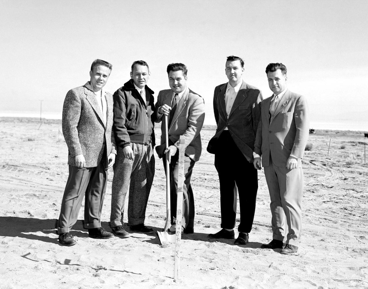
The NACA High-Speed Flight Research Station, had initially been subordinate to the Langley Memorial Aeronautical Laboratory near Hampton, Virginia, but as the flight research in the Mojave Desert increasingly proved its worth after 1946, it made sense to make the Flight Research Station a separate entity reporting directly to the headquarters of the National Advisory Committee for Aeronautics. But an autonomous center required all the trappings of a major research facility, including good quarters. With the adoption of the Edwards “Master Plan,” the Air Force had committed itself to moving from its old South Base to a new location midway between the South and North Bases. The NACA would have to move also--so why not take advantage of the situation and move into a full-blown research facility. The Air Force issued a lease to NACA for a location on the northwestern shore of the Roger Dry Lake. Construction started on the NACA station in early February 1953. On a windy day, January 27, 1953, at a groundbreaking ceremony stood left to right: Gerald Truszynski, Head of Instrumentation Division; Joseph Vensel, Head of the Operations Branch; Walter Williams, Head of the Station, scooping the first shovel full of dirt; Marion Kent, Head of Personnel; and California state official Arthur Samet.