
Launch of a three-stage Vanguard (SLV-7) from Cape Canaveral, Florida, September 18, 1959. Designated Vanguard III, the 100-pound satellite was used to study the magnetic field and radiation belt. In September 1955, the Department of Defense recommended and authorized the new program, known as Project Vanguard, to launch Vanguard booster to carry an upper atmosphere research satellite in orbit. The Vanguard vehicles were used in conjunction with later booster vehicle such as the Thor and Atlas, and the technique of gimbaled (movable) engines for directional control was adapted to other rockets.
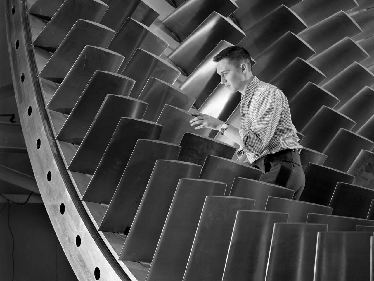
An engineer examines the main compressor for the 10- by 10-Foot Supersonic Wind Tunnel at the National Advisory Committee for Aeronautics (NACA) Lewis Flight Propulsion Laboratory. The engineers were preparing the new wind tunnel for its initial runs in early 1956. The 10- by 10 was the most powerful propulsion wind tunnel in the nation. The facility was part of Congress’ Unitary Plan Act which coordinated wind tunnel construction at the NACA, Air Force, industry, and universities. The 10- by 10 was the largest of the three NACA tunnels built under the act. The 20-foot diameter eight-stage axial flow compressor, seen in this photograph, could generate air flows up to Mach 2.5 through the test section. The stainless steel compressor had 584 blades ranging from 1.8 to 3.25 feet in length. This main compressor was complemented by a secondary axial flow compressor. Working in tandem the two could generate wind streams up to Mach 3.5. The Cleveland Chamber of Commerce presented NACA Lewis photographer Bill Bowles with a second place award for this photograph in their Business and Professional category. The photograph was published in October 1955 edition of its periodical, The Clevelander, which highlighted local professional photographers. Fellow Lewis photographer Gene Giczy won second place in another category for a photograph of Cleveland Municipal Airport.
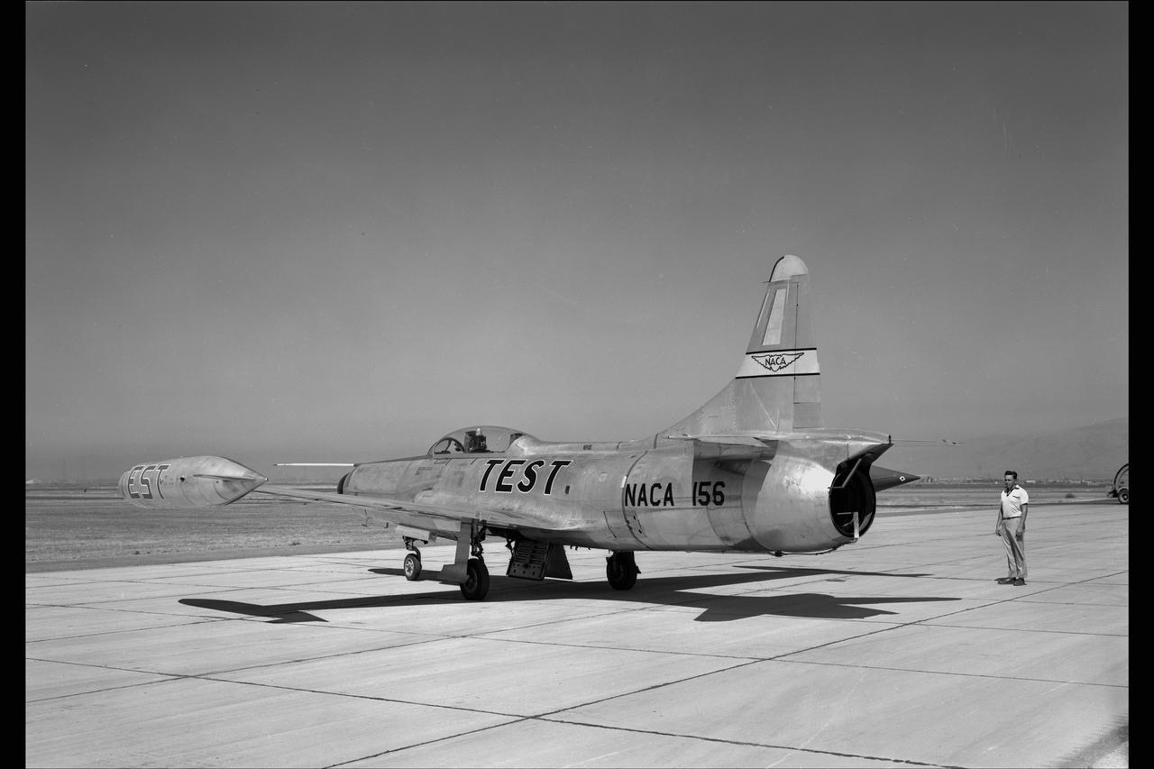
LOCKHEED F-94C #156 AIRPLANE. COOLING AIR EJECTOR on NACA Ames Flight Line
An apprentice at the National Advisory Committee for Aeronautics (NACA) Lewis Flight Propulsion Laboratory shown training on the altitude supply air systems in the Engine Research Building. An ongoing four-year apprentice program was established at the laboratory in 1949 to facilitate the close interaction of the lab’s engineers, mechanics, technicians, and scientists. The apprentice school covered a variety of trades including aircraft mechanic, electronics instrumentation, machinist, and altitude systems mechanic, seen in this photograph. The apprentices rotated through the various shops and facilities to provide them with a well-rounded understanding of the work at the lab. The specialized skills required meant that NACA apprentices were held to a higher standard than those in industry. They had to pass written civil service exams before entering the program. Previous experience with mechanical model airplanes, radio transmission, six months of work experience, or one year of trade school was required. The Lewis program was certified by both the Department of Labor and the State of Ohio. One hundred fifty of the 2,000 hours of annual training were spent in the classroom. The remainder was devoted to study of models and hands-on work in the facilities. Examinations were coupled with evaluation by supervisors in the shops. The apprentices were promoted through a series of grades until they reached journeyman status. Those who excelled in the Apprentice Program would be considered for a separate five-year engineering draftsman program.
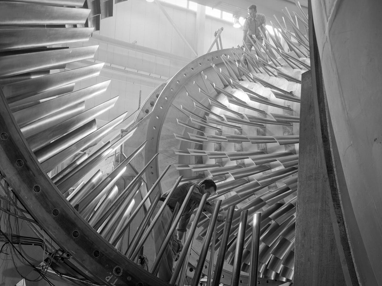
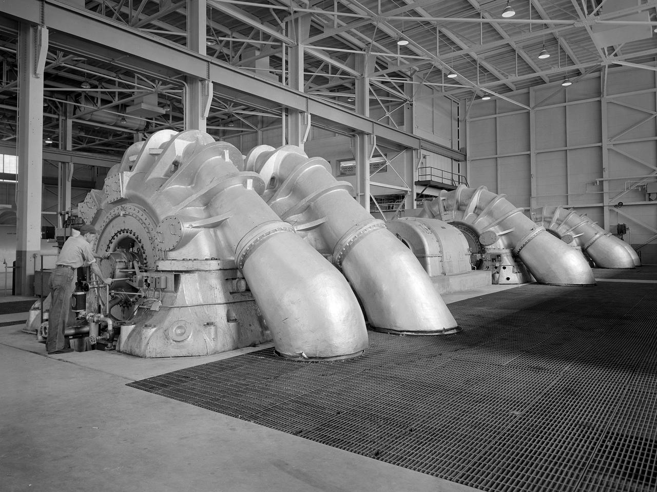
A mechanic checks the tubing on one of the many jacks which control the nozzle section of the 10- by 10-Foot Supersonic Wind Tunnel at the National Advisory Committee for Aeronautics (NACA) Lewis Flight Propulsion Laboratory. The 10- by 10-foot tunnel, which had its official opening in May 1956, was built under the Congressional Unitary Plan Act which coordinated wind tunnel construction at the NACA, Air Force, industry, and universities. The 10- by 10 was the largest of the three NACA tunnels built under the act. The 10- by 10 wind tunnel can be operated as a closed circuit for aerodynamic tests or as an open circuit for propulsion investigations. The 10-foot tall and 76-foot long stainless steel nozzle section just upstream from the test section can be adjusted to change the speed and composition of the air flow. Hydraulic jacks, seen in this photograph, flex the 1.37-inch thick walls of the tunnel nozzle. The size of the nozzle’s opening controls the velocity of the air through the test section. Seven General Electric motors capable of generating 25,000 horsepower produce the Mach 2.5 and 2.5 airflows. The facility was mostly operated at night due to its large power load requirements.
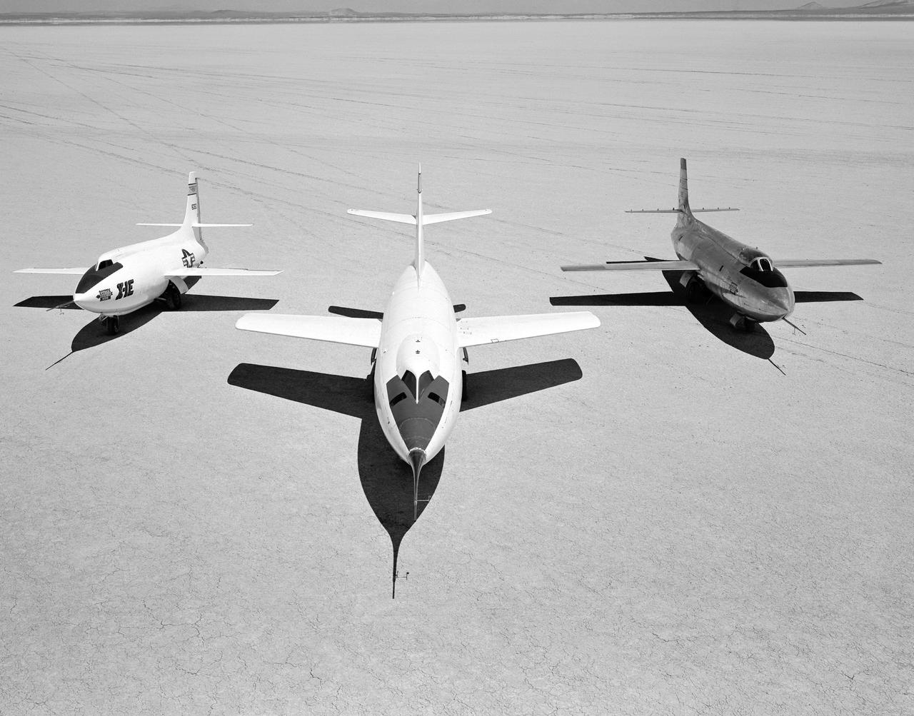
Early NACA research aircraft on the lakebed at the High Speed Research Station in 1955: Left to right: X-1E, D-558-II, X-1B
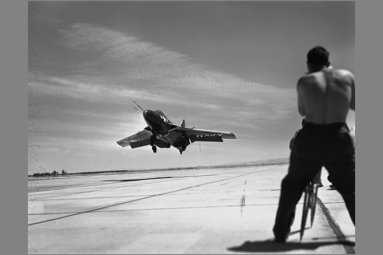
Navy CHANCE VOUGHT F7U-3 #656 AIRPLANE on NACA Ames flight line
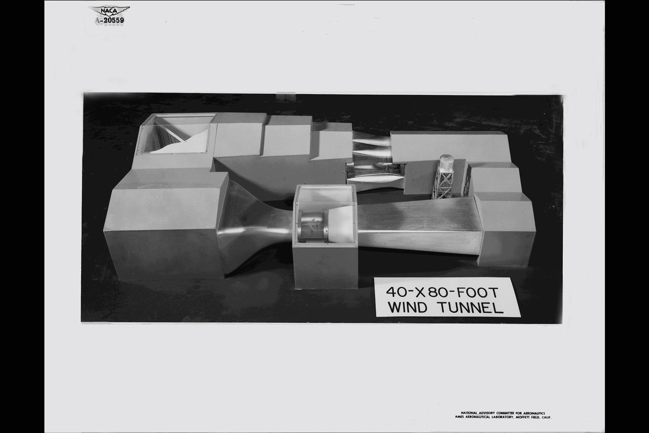
MODEL OF NACA Ames Research Center's 40 BY 80 FOOT SUBSONIC WIND TUNNEL.
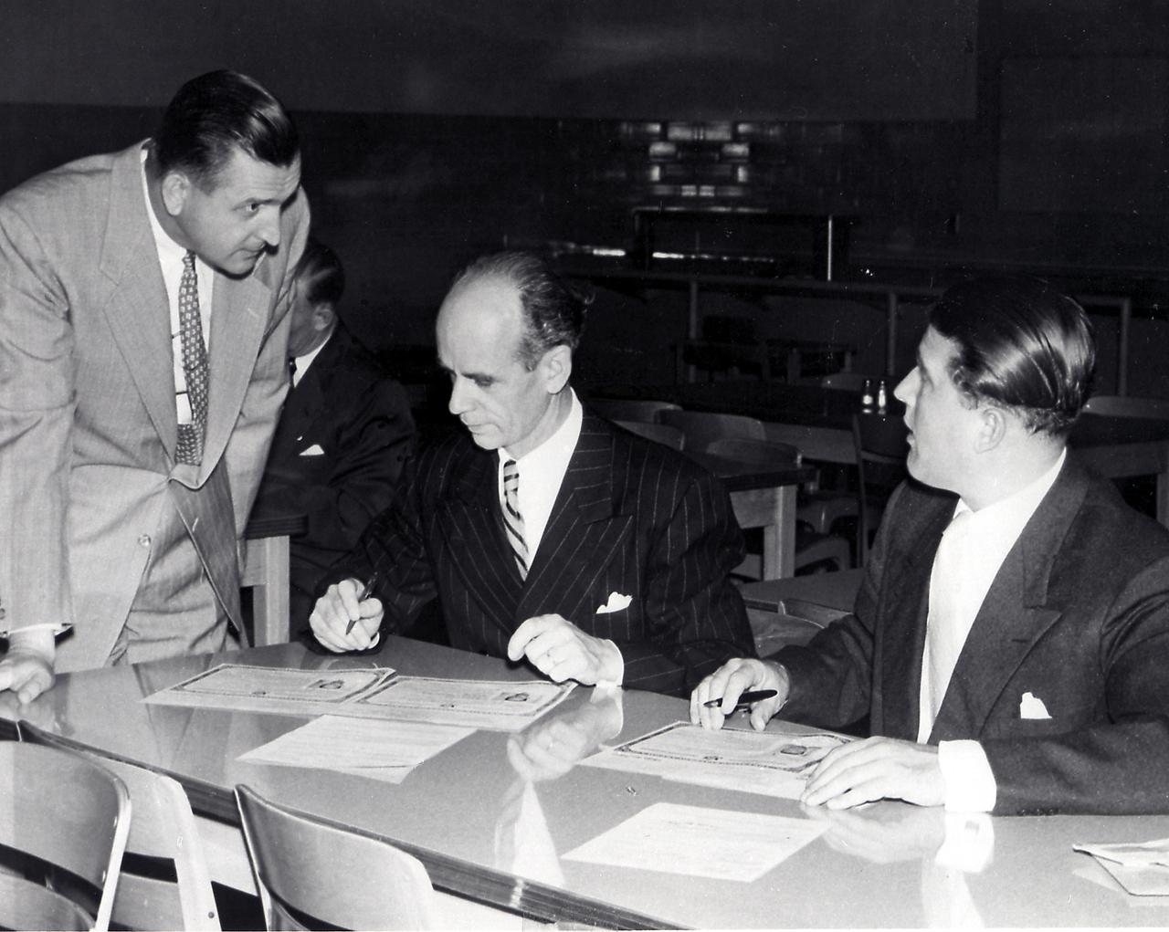
The members of the Peenemuende team and their family members were awarded the United States citizenship on April 14, 1955. Pictured here is Dr. Ernst Stuhlinger (middle) and Dr. Wernher von Braun signing U.S. citizenship certificates. Martin Schilling is at left.
The Ames 40 by 80 foot full scale wind tunnel could just accommodate the 72.5 foot wingspan of the Douglas A3D Sky warrior. Date unknown. -: Unknown film. SBA settings neutral SBA on, color SBA on
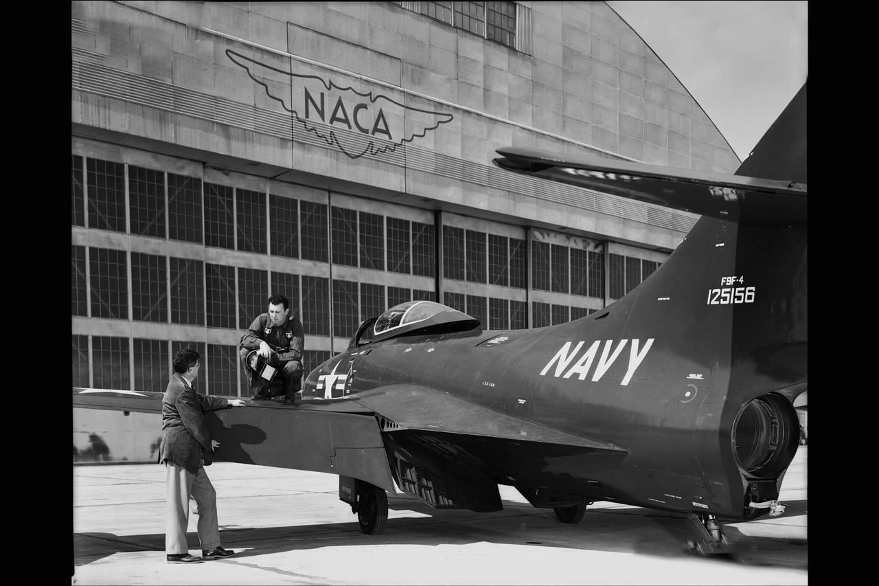
Navy - GRUMAN F9F-4 AIRPLAN with NACA PILOTS INNIS & ROLLS on NACA Ames ramp in front of Hangar 211
NACA Ames Research Center 14' TRANSONIC WIND TUNNEL SURVEY TUBE.
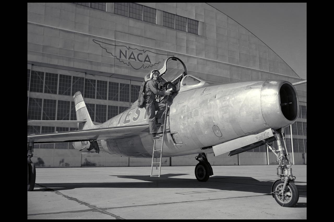
91,591 Overhead view. McDonnell XF-88B Experimental Jet Fighter. Langley used this aircraft in the mid-1950s to explore the potential of a supersonic propeller. Photographed in Engineer in Charge A History of the Langley Aeronautical Laboratory, 1917-1958 by James R. Hansen. Page 508. **Note see L57-2259 for eye level view.
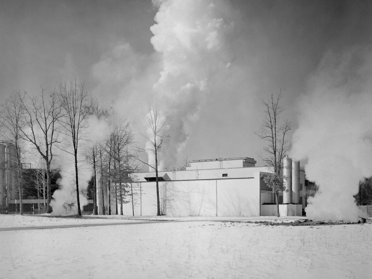
The Engine Propeller Research Building, referred to as the Prop House, emits steam from its acoustic silencers at the National Advisory Committee for Aeronautics (NACA) Lewis Flight Propulsion Laboratory. In 1942 the Prop House became the first completed test facility at the new NACA laboratory in Cleveland, Ohio. It contained four test cells designed to study large reciprocating engines. After World War II, the facility was modified to study turbojet engines. Two of the test cells were divided into smaller test chambers, resulting in a total of six engine stands. During this period the NACA Lewis Materials and Thermodynamics Division used four of the test cells to investigate jet engines constructed with alloys and other high temperature materials. The researchers operated the engines at higher temperatures to study stress, fatigue, rupture, and thermal shock. The Compressor and Turbine Division utilized another test cell to study a NACA-designed compressor installed on a full-scale engine. This design sought to increase engine thrust by increasing its airflow capacity. The higher stage pressure ratio resulted in a reduction of the number of required compressor stages. The last test cell was used at the time by the Engine Research Division to study the effect of high inlet densities on a jet engine. Within a couple years of this photograph the Prop House was significantly altered again. By 1960 the facility was renamed the Electric Propulsion Research Building to better describe its new role in electric propulsion.
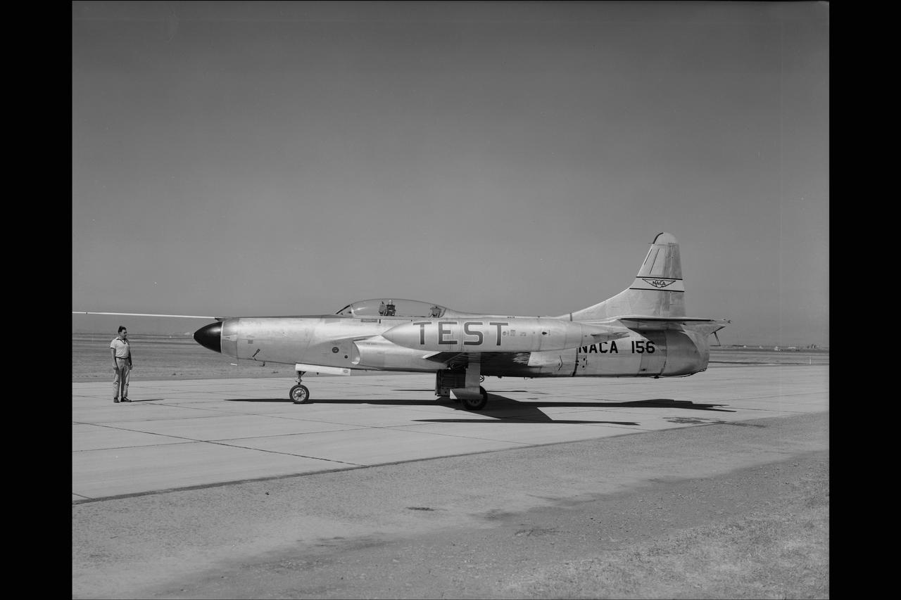
LOCKHEED F-94C #156 AIRPLANE. COOLING AIR EJECTOR on NACA Ames Flight Line
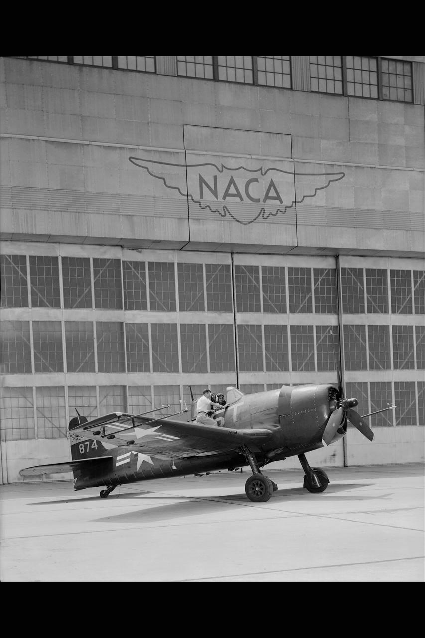
GRUMMAN F6F-3 #874 AIRPLANE on the NACA Ames flight line
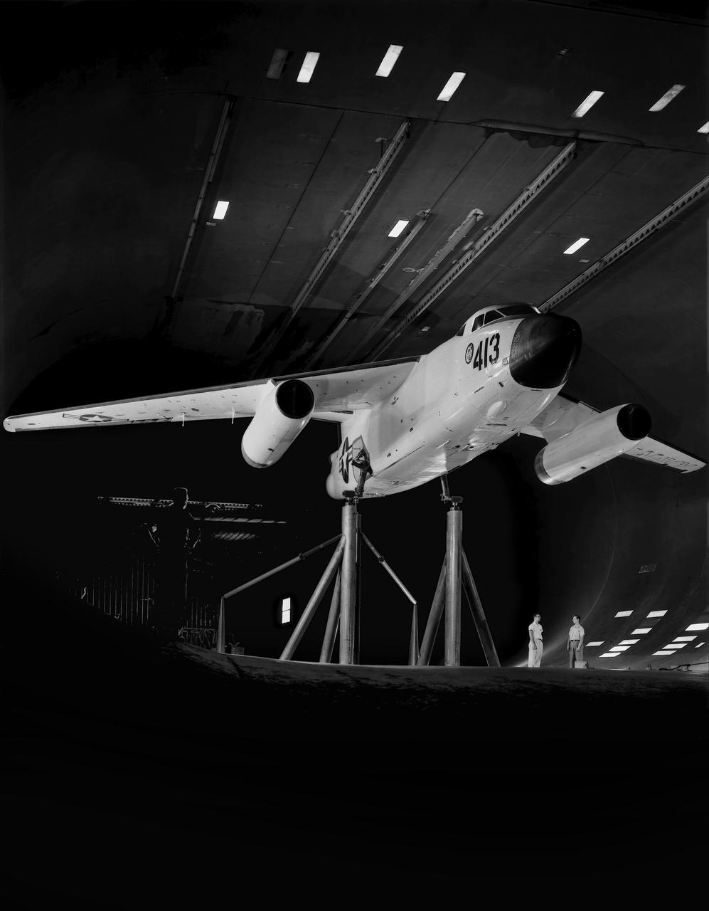
Testing the wing boundary layer control of the A3D in the 40 x 80 wind tunnel. Boundary layer control was added to increase the lift of the wing for aircraft carrier take off and landing.
The Propulsion Systems Laboratory’s exhaust system was expanded in 1955 at the National Advisory Committee for Aeronautics (NACA) Lewis Flight Propulsion Laboratory. The facility contained two altitude chambers that were first used to study the increasingly-powerful jet engines of the early 1950s and the ramjets for missile programs such as Navaho and Bomarc. Later, the facility tested large rocket engines and a variety of turbofan engines. The exhaust system served two roles: reducing the density of the air in the test chambers to simulate high altitudes and removing the hot gases exhausted by the engines being tested. These tasks were accomplished by large Roots-Connersville exhauster equipment in the Equipment Building. The original configuration could exhaust the 3500° F gases at a rate of 100 pounds per second when the simulated altitude was 50,000 feet. In 1955, three years after operation started, a fourth line of exhausters was added. There were three centrifugal exhausters capable of supplying 166 pounds of air per second at the test chamber altitude of 50,000 feet or 384 pounds per second at 32,000 feet. These exhausters had two first-stage castings driven by a 10,000-horsepower motor; one second; one third; and one fourth-stage casting driven by a 16,500-horsepower motor. The total inlet volume of the exhausters is 1,650,000 cubic feet of gas per minute. The exhausters were continually improved and upgraded over the years.
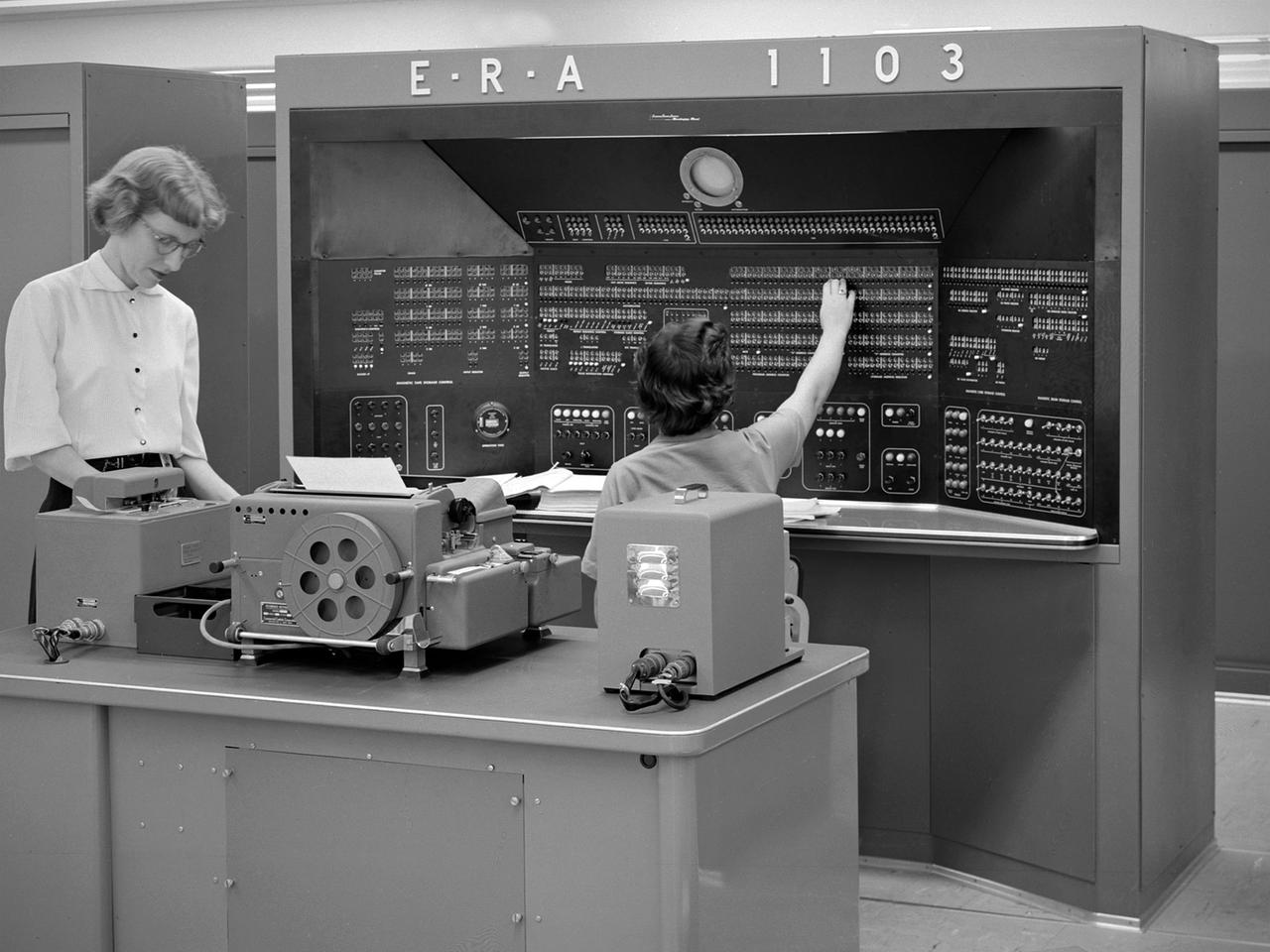
The new 10-by 10-Foot Supersonic Wind Tunnel at the Lewis Flight Propulsion Laboratory included high tech data acquisition and analysis systems. The reliable gathering of pressure, speed, temperature, and other data from test runs in the facilities was critical to the research process. Throughout the 1940s and early 1950s female employees, known as computers, recorded all test data and performed initial calculations by hand. The introduction of punch card computers in the late 1940s gradually reduced the number of hands-on calculations. In the mid-1950s new computational machines were installed in the office building of the 10-by 10-Foot tunnel. The new systems included this UNIVAC 1103 vacuum tube computer—the lab’s first centralized computer system. The programming was done on paper tape and fed into the machine. The 10-by 10 computer center also included the Lewis-designed Computer Automated Digital Encoder (CADDE) and Digital Automated Multiple Pressure Recorder (DAMPR) systems which converted test data to binary-coded decimal numbers and recorded test pressures automatically, respectively. The systems primarily served the 10-by 10, but were also applied to the other large facilities. Engineering Research Associates (ERA) developed the initial UNIVAC computer for the Navy in the late 1940s. In 1952 the company designed a commercial version, the UNIVAC 1103. The 1103 was the first computer designed by Seymour Cray and the first commercially successful computer.

Navy - NORTH AMERICAN FJ-3 #800 AIRPLANe on the NACA Ames flight line
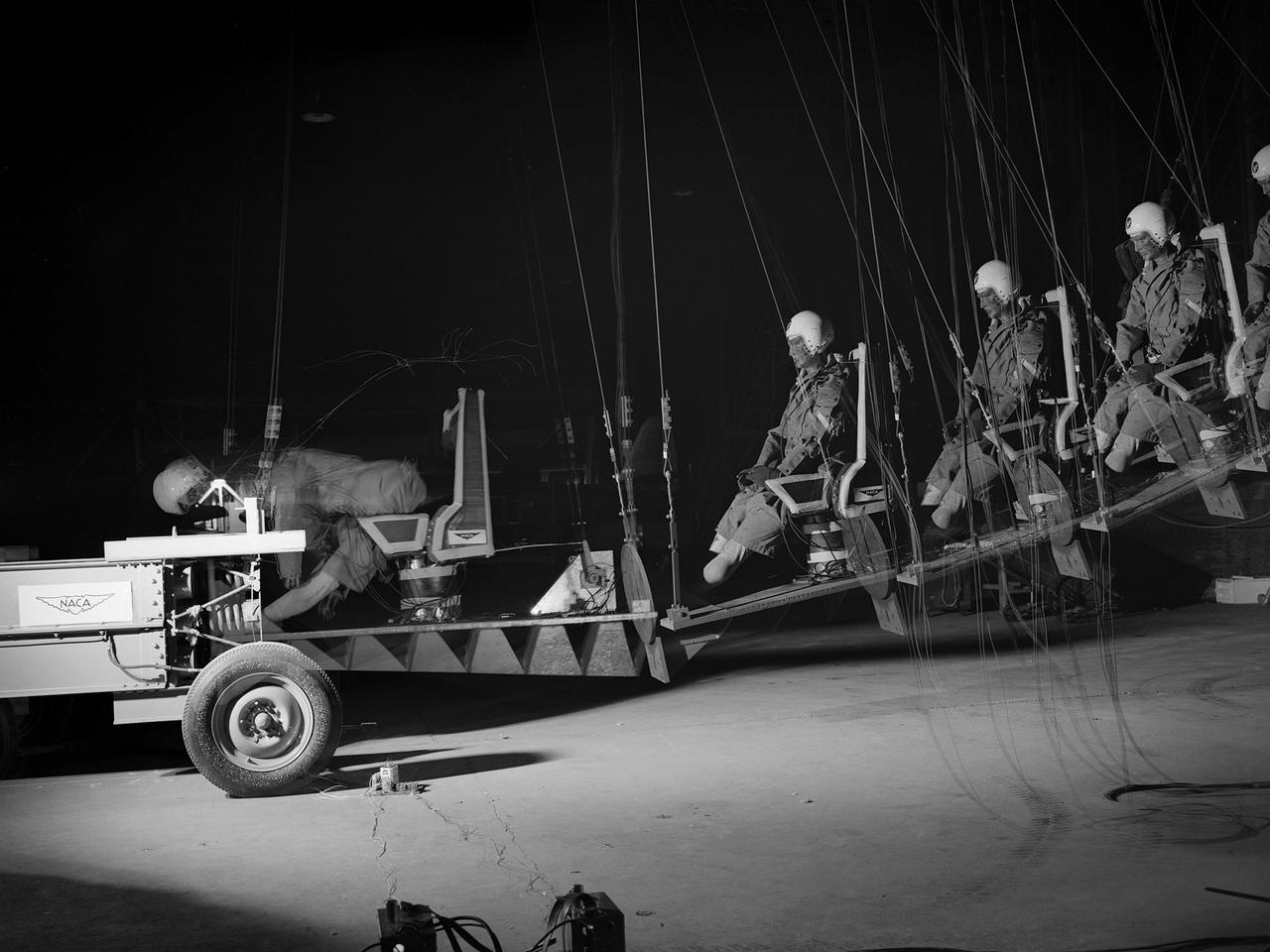
This time-lapse photograph shows the test of a pilot seat and restraint designed by researchers at the National Advisory Committee for Aeronautics (NACA) Lewis Flight Propulsion Laboratory. The laboratory had undertaken a multi-year investigation into the causes and preventative measures for fires resulting from low altitude aircraft crashes. The program was expanded in the mid-1950s to include the study of crash impact on passengers, new types of types of seat restraints, and better seat designs. The impact program began by purposely wrecking surplus transport Fairchild C-82 Packet and Piper Cub aircraft into barricades at the end of a test runway. Instrumented dummies and cameras were installed in the pilot and passenger areas. After determining the different loads experienced during a crash and the effects on the passengers, the NACA researchers began designing new types of seats and restraints. The result was an elastic seat that flexed upon impact, absorbing 75 percent of the loads before it slowly recoiled. This photograph shows the seats mounted on a pendulum with a large spring behind the platform to provide the jolt that mimicked the forces of a crash. The seat was constructed without any potentially damaging metal parts and included rubber-like material, an inflated back and arms, and a seat cushion. After the pendulum tests, the researchers compared the flexible seats to the rigid seats during a crash of a transport aircraft. They found the passengers in the rigid seats received 66 percent higher g-forces than the NACA-designed seats.
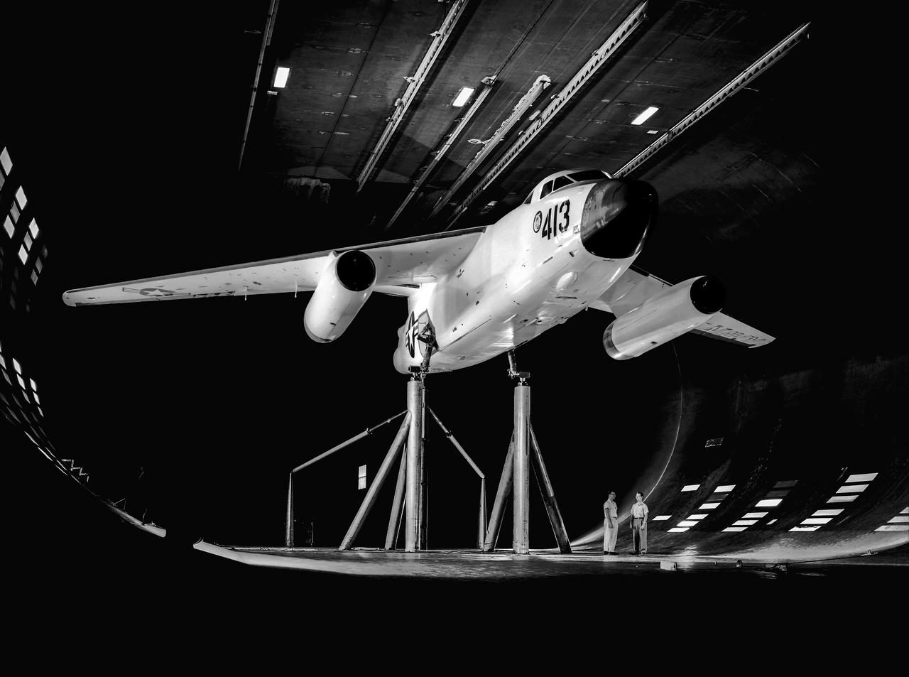
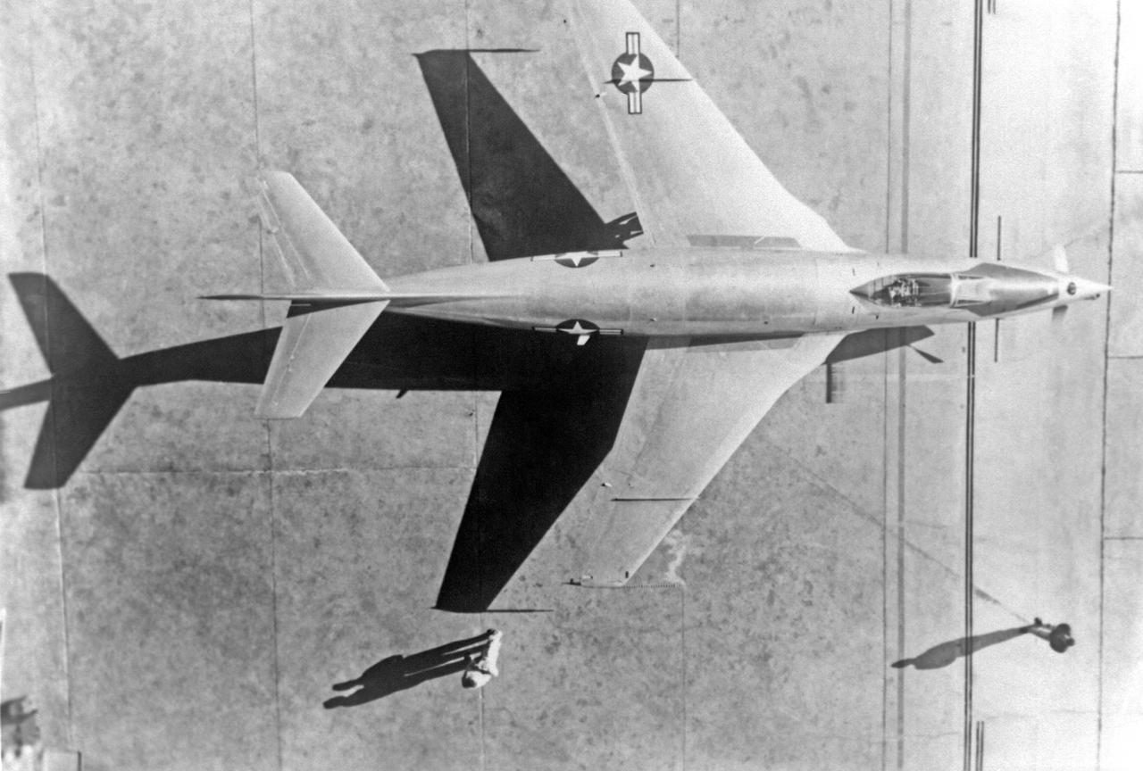
DOUGLAS XA3D-1 #413 AIRPLANE MOUNTED IN THE NACA AMES RESEARCH CENTER'S 40X80_FOOT SUBSONIC WIND TUNNEL sweptback wing Testing the wing boundary layer control of the A3D in the 40 x 80 wind tunnel. Boundary layer control was added to increase the lift of the wing for aircraft carrier take off and landing.
Ames Pilot George Cooper and F-84F airplane on ramp
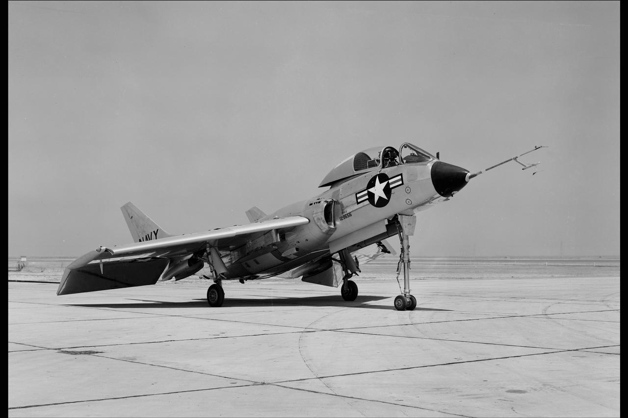
CHANCE VOUGHT F7U-3 #656 AIRPLANE at NACA Ames for testing of PRESSURE PROBE ON TAIL PIPE (afterburners)
Grumman F9F-6 (Bu. No. 128138) Cougar airplane. EVALUATION OF CARRIER APPROACH TECHNIQUES Boundary Layer Control, STOL, and V/STOL Note: Used in publication in Flight Research at Ames; 57 Years of Development and Validation of Aeronautical Technology NASA SP-1998-3300 fig. 101
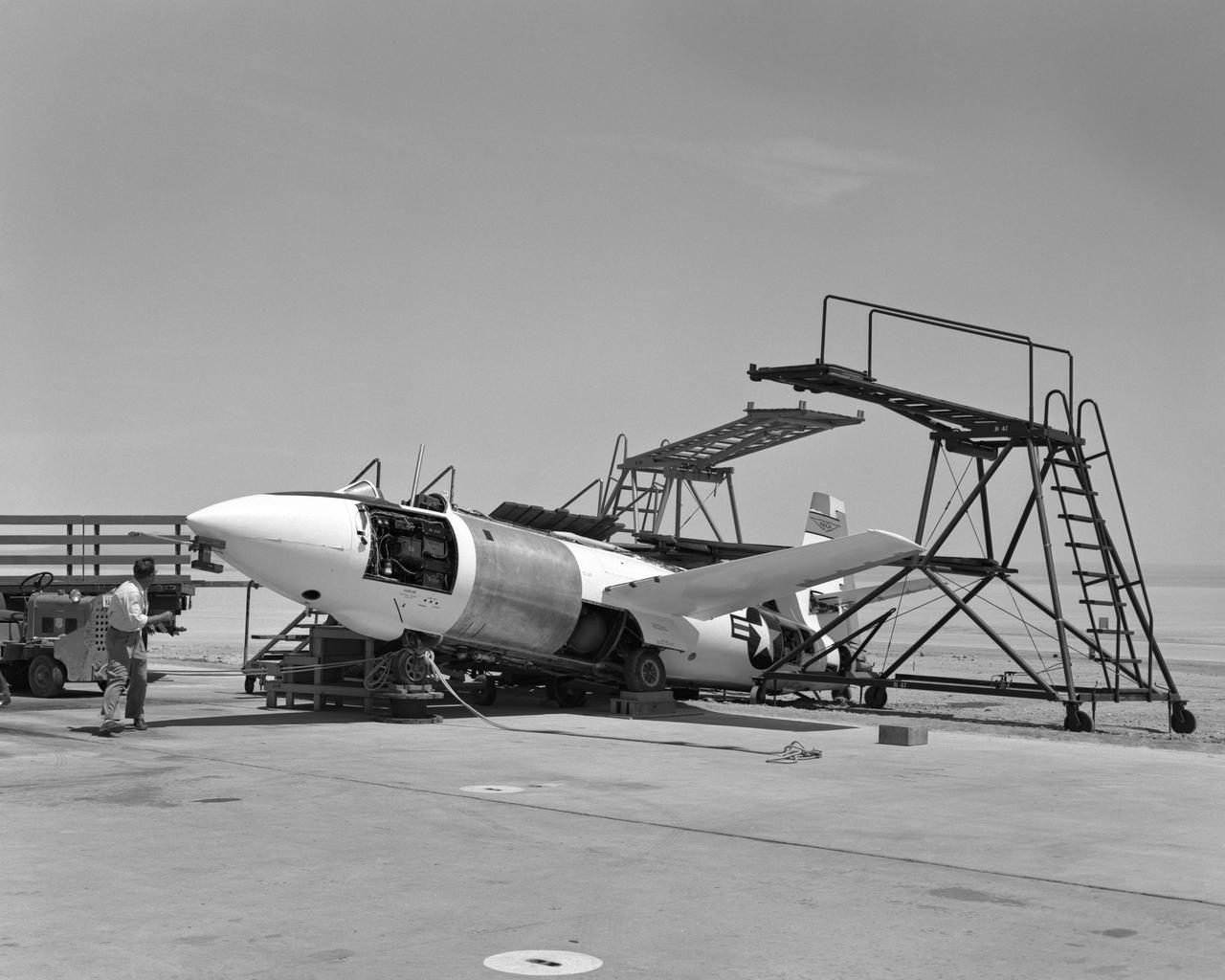
Bell X-1A ejection seat test setup
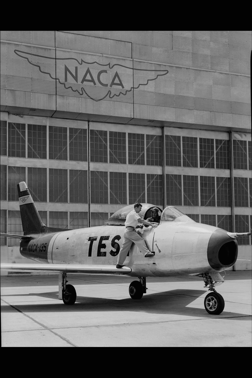
NORTH AMERICAN F86-A #135 AIRPLANE on Ames ramp in front of hangar 211 with NACA PILOTS COOPER & CREER
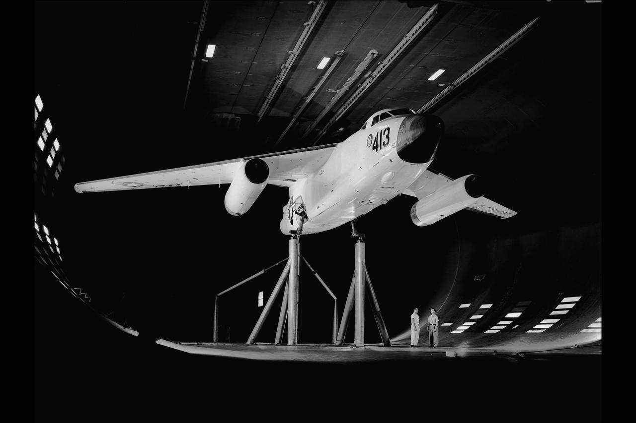
DOUGLAS XA3D-1 #413 AIRPLANE MOUNTED IN THE NACA AMES RESEARCH CENTER'S 40X80_FOOT SUBSONIC WIND TUNNEL Testing the boundary layer control of the A3D in the 40 x 80 wind tunnel. Boundary layer control was added to increase the lift of the wing for take off from an aircraft carrier.
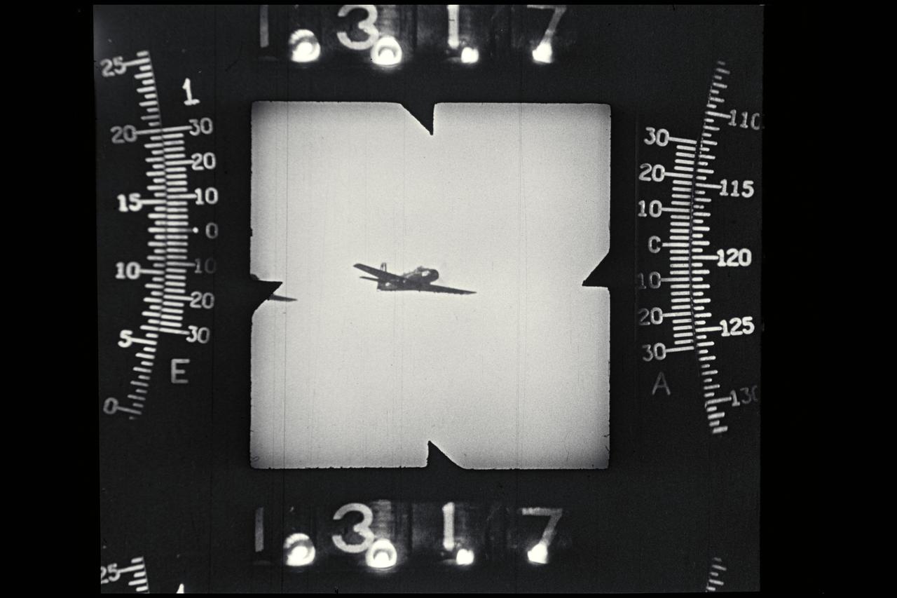
NACA photographer: Phototheodolite camera record image of P-51 in flight propellers on
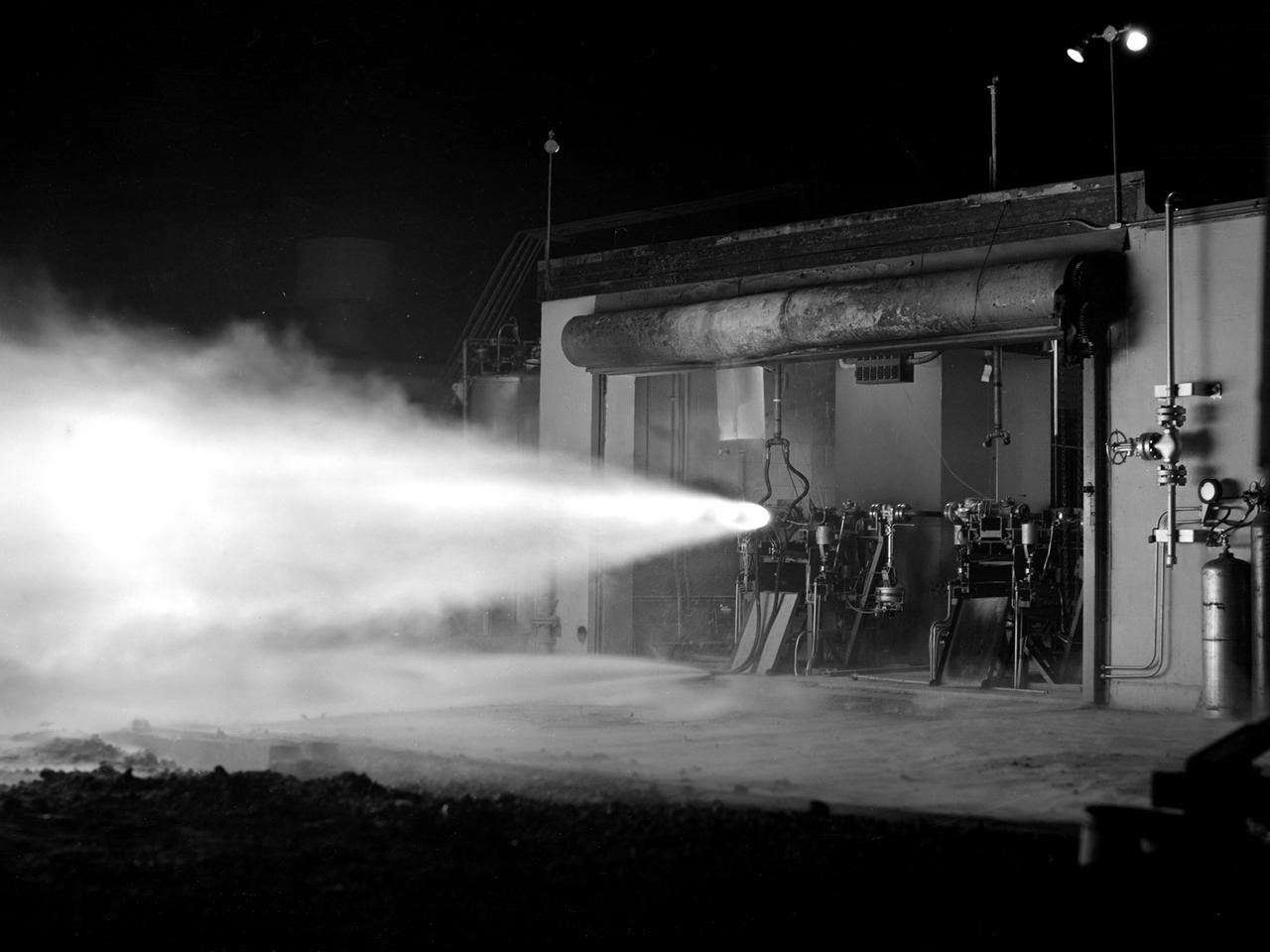
A rocket using high-energy propellant is fired from the Rocket Laboratory at the National Advisory Committee for Aeronautics (NACA) Lewis Flight Propulsion Laboratory. The Rocket Lab was a collection of ten one-story cinderblock test cells located behind earthen barriers at the western edge of the campus. The rocket engines tested there were comparatively small, but the Lewis researchers were able to study different configurations, combustion performance, and injectors and nozzle design. The rockets were generally mounted horizontally and fired, as seen in this photograph of Test Cell No. 22. A group of fuels researchers at Lewis refocused their efforts after World War II in order to explore high energy propellants, combustion, and cooling. Research in these three areas began in 1945 and continued through the 1960s. The group of rocket researches was not elevated to a division branch until 1952. The early NACA Lewis work led to the development of liquid hydrogen as a viable propellant in the late 1950s. Following the 1949 reorganization of the research divisions, the rocket group began working with high-energy propellants such as diborane, pentaborane, and hydrogen. The lightweight fuels offered high levels of energy but were difficult to handle and required large tanks. In late 1954, Lewis researchers studied the combustion characteristics of gaseous hydrogen in a turbojet combustor. Despite poor mixing of the fuel and air, it was found that the hydrogen yielded more than a 90-percent efficiency. Liquid hydrogen became the focus of Lewis researchers for the next 15 years.
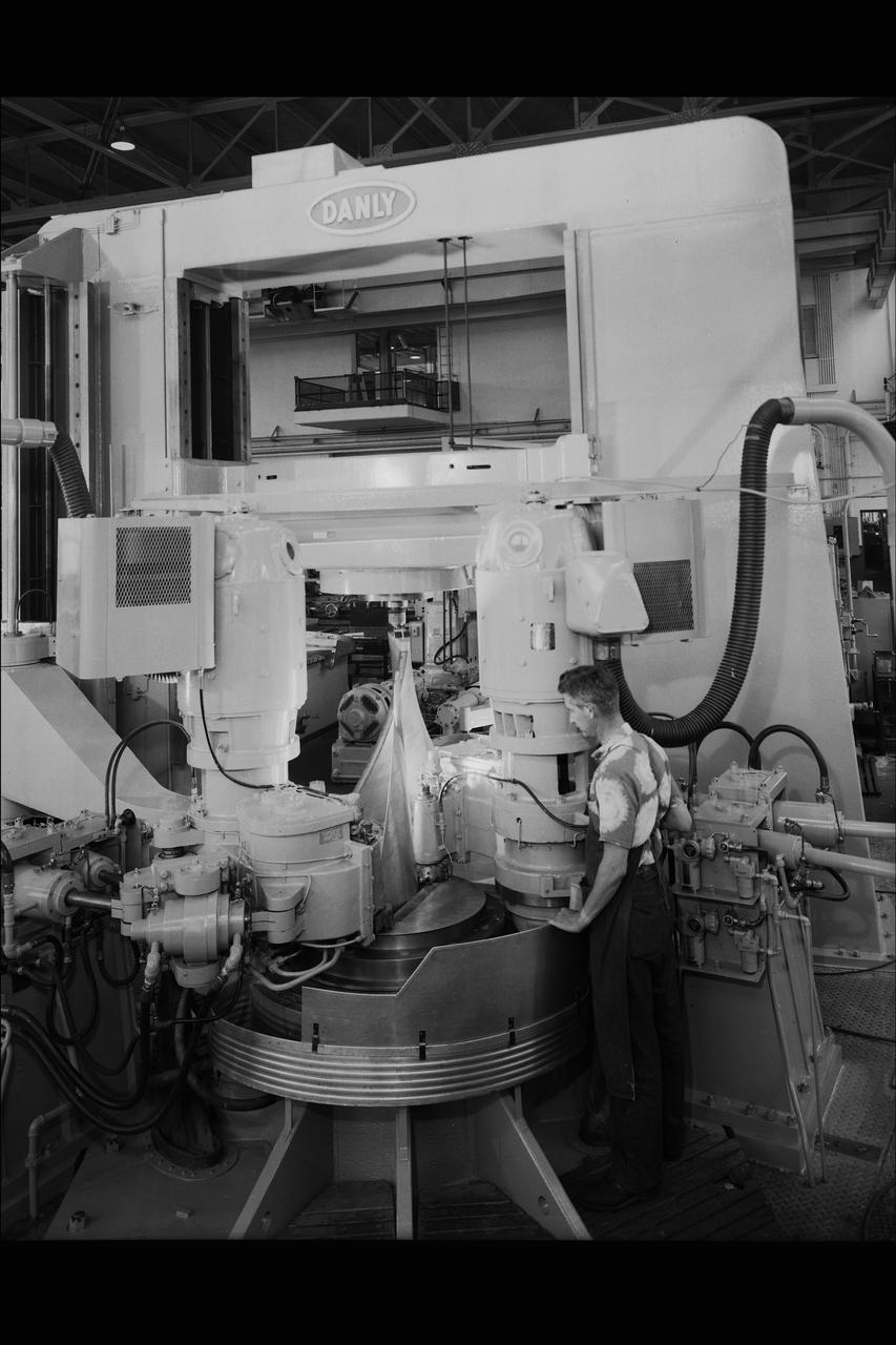
DANLY AIRFOIL CUTTING MACHINE.
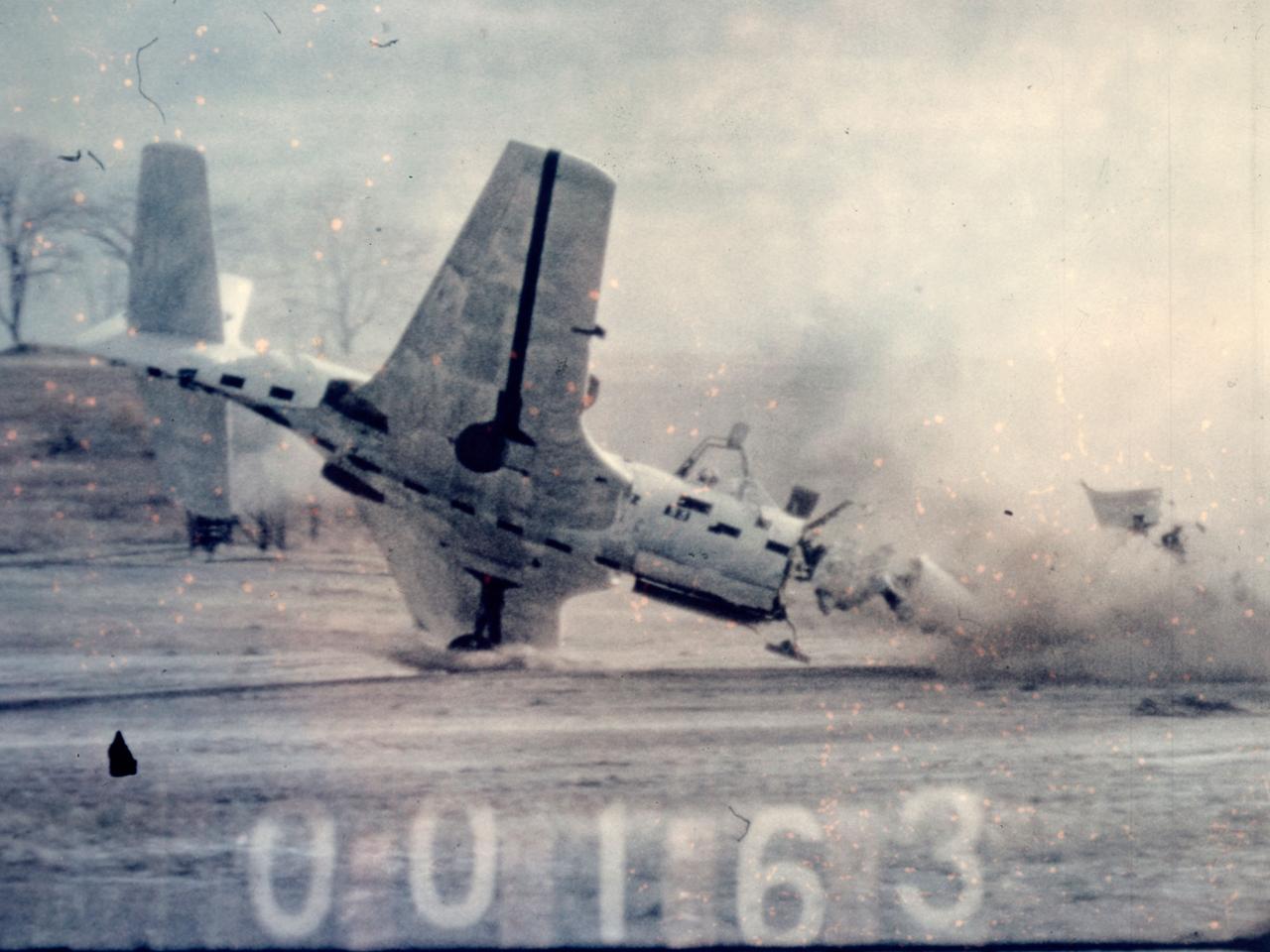
Researchers at the National Advisory Committee for Aeronautics (NACA) Lewis Flight Propulsion Laboratory purposely wreck a McDonnell FH-1 Phantom as part of the laboratory’s Crash Fire Program. NACA Lewis researchers created the program in 1949 to investigate methods for improving survival rates for take-off and landing-type crashes. In these types of crashes, the passengers often survived the impact only to perish in the ensuing fire. Previously there had been little information on the nature of post-crash fires, and it was difficult to use analytical studies in this area. Irving Pinkel, Chief of the Lewis Flight Propulsion Division, was the primary researcher. He enlisted flight safety specialist and aeronautics researchers G. Merritt Preston and Gerard Pesman, mechanical engineer Dugald Black, and others. The tests were conducted at the nearby Ravenna Arsenal using decommissioned Air Force fighter and transport aircraft. The pilotless aircraft were accelerated down a rail on a 1700-foot track at take-off speeds and run into barriers to simulate a variety of different types of crashes. The first barrier stripped off the landing gears and another briefly sent the aircraft off the ground before it crashed into a dirt mound. Telemetry and high-speed cameras were crucial elements in these studies. NACA Lewis photographer Bill Wynne developed a method for inserting timekeeping devices on test film that were able to show time to one thousandth of a second.
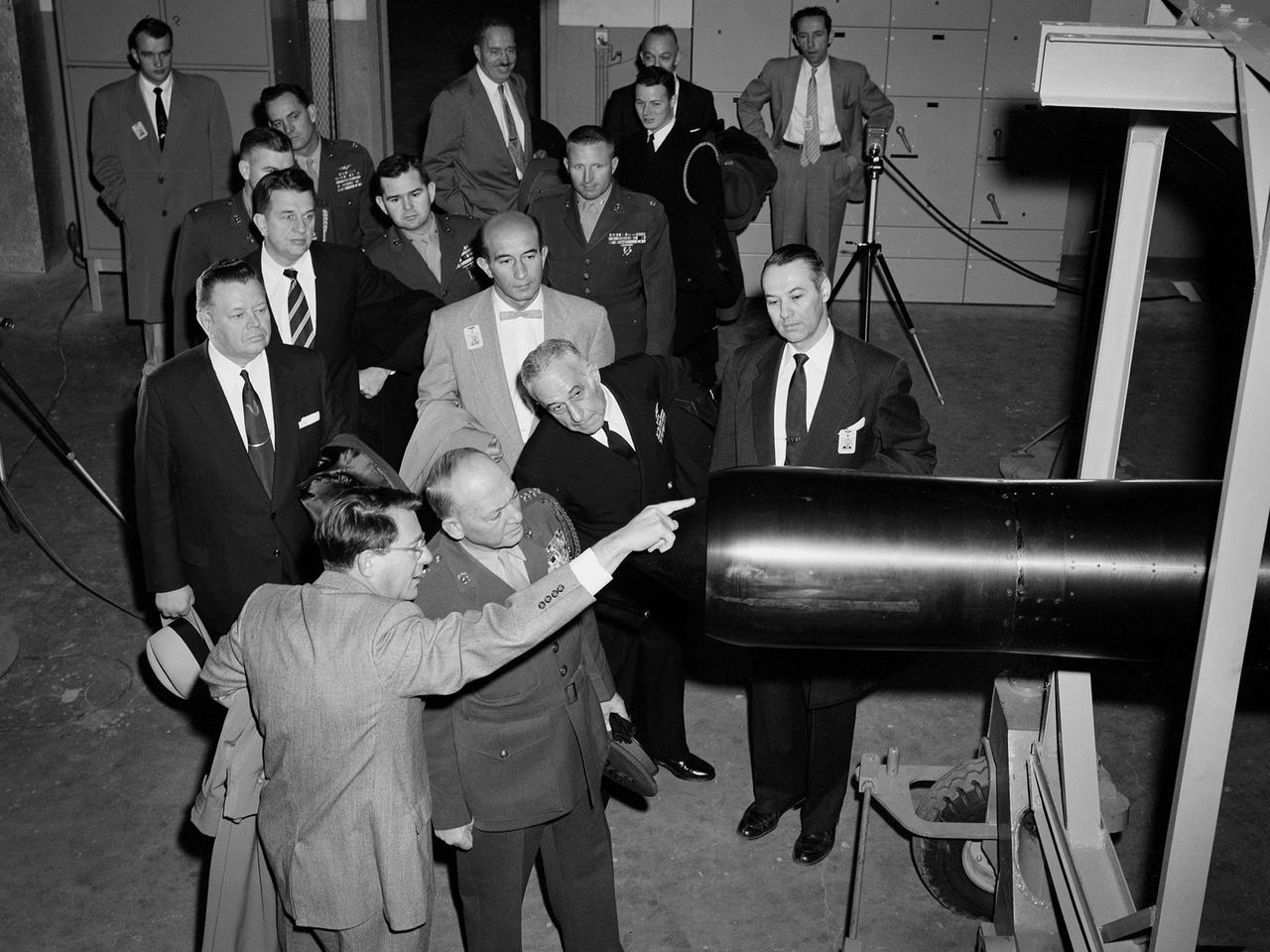
Abe Silverstein, Associate Director of the National Advisory Committee for Aeronautics (NACA) Lewis Flight Propulsion Laboratory, provides a personal tour of the new 10- by 10-Foot Supersonic Wind Tunnel for US Senator George Bender (hat in hand) and General Lemuel Shepherd. Shepherd was Commandant of the Marine Corps and had served in World War I, World War II, and the Korean War. The general was accompanied by Admiral Herbert Leary, in dark uniform. Bender was a Republican Senator from Ohio. Behind Bender is President of the Cleveland Chamber of Commerce Curtis Smith. NACA Lewis managers Eugene Manganiello and Wilson Hunter assist with the tour. Abe Silverstein oversaw all research at the laboratory. Upon taking his post in 1952 he reorganized the research staff and began shifting the focus away from airbreathing aircraft engines to new fields such as high energy fuels, electric propulsion, and nuclear power and propulsion. He was an early advocate of the NACA’s involvement in the space program and crucial to the founding of National Aeronautics and Space Administration in 1958. Silverstein began his career helping design and conduct research in the Full Scale Tunnel in 1929 at the Langley Memorial Aeronautical Laboratory. Silverstein advocated a series of increasingly large supersonic wind tunnels after the war, culminating in the 10- by 10.