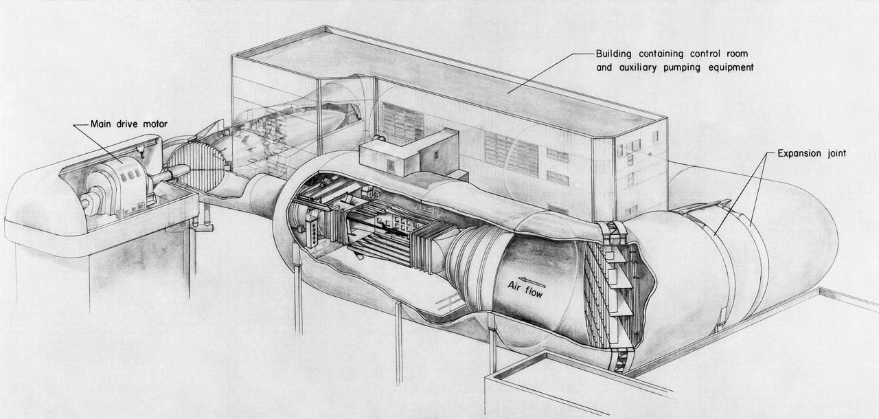
Drawing of the 8-Foot Transonic Pressure Tunnel.

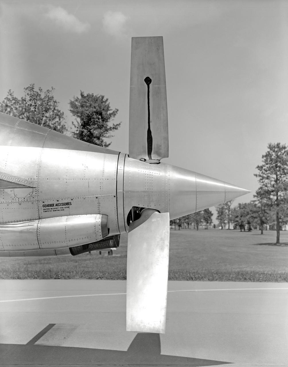
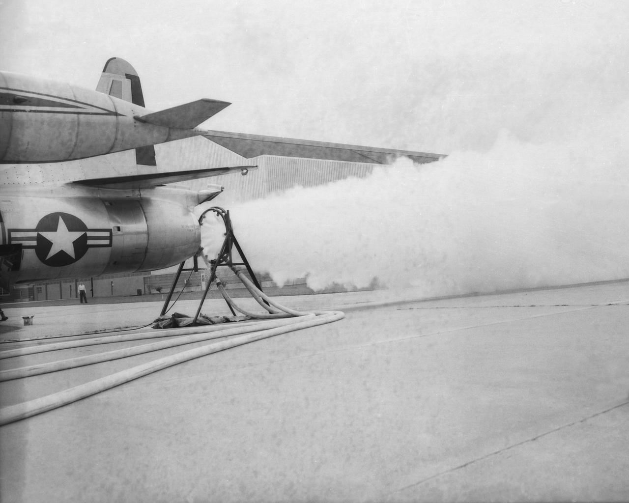
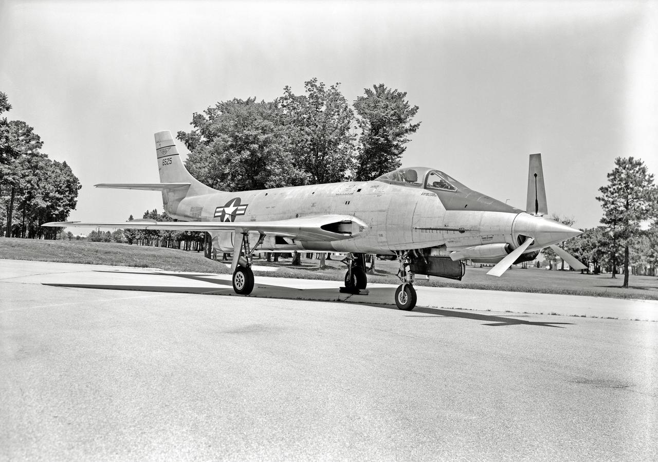
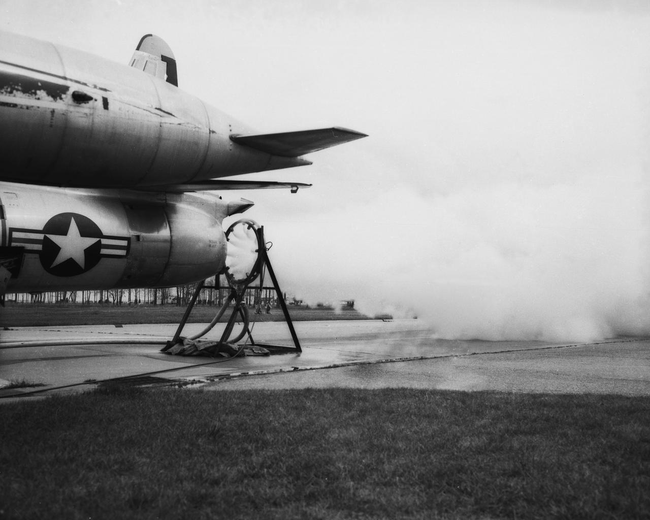
Phase SB Propeller installed on F88B
North American F-100 Airplane (NACA 709), with Pilot George Cooper
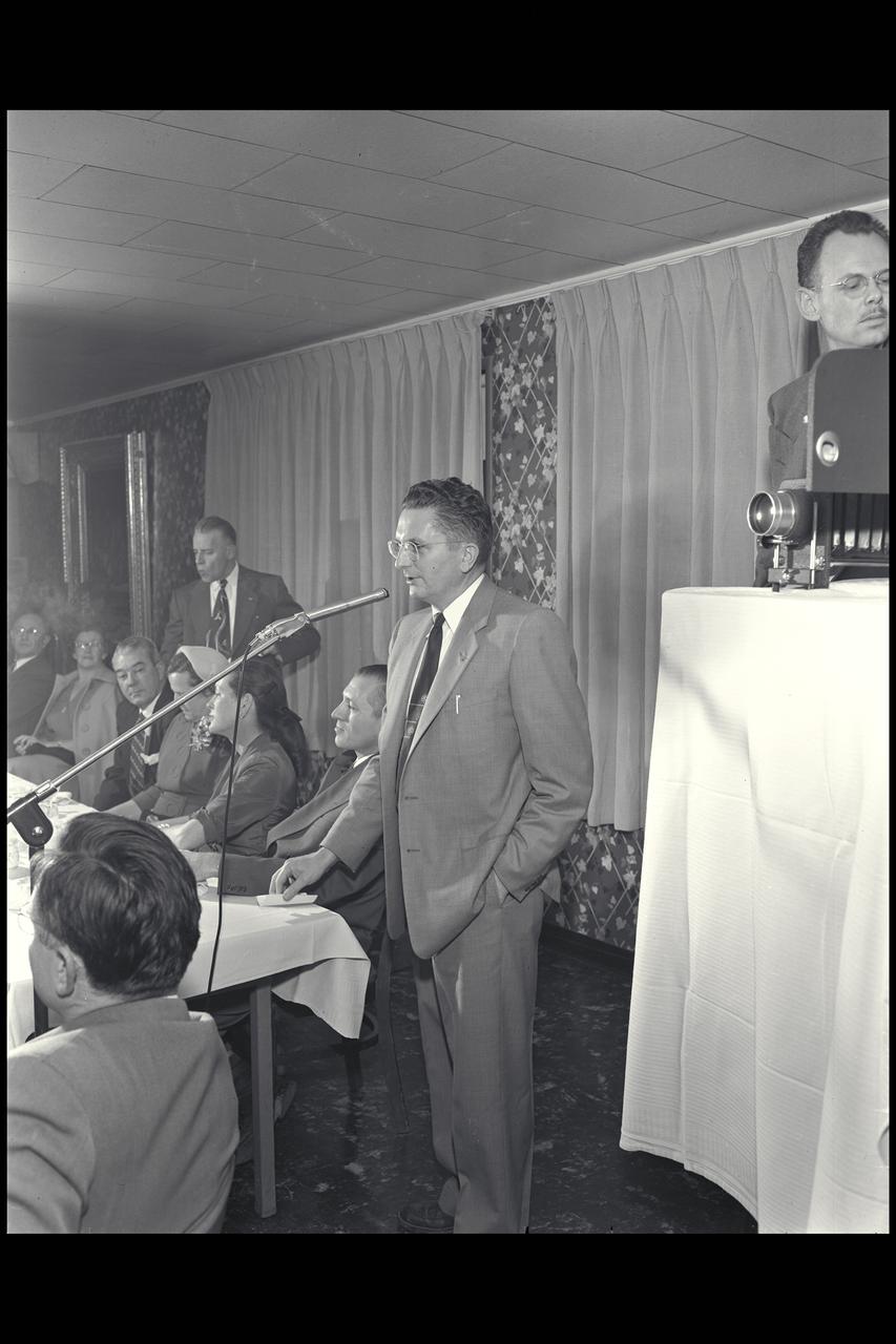
Harry J. Goett with Larry Clousing (seated next to him at head table) during William McAvoy (seat at middle of table) testimonial dinner. Publication: Atmosphere of Freedom; 60 yrs. of Ames - NASA SP
WS-110A "Brown Bomber"

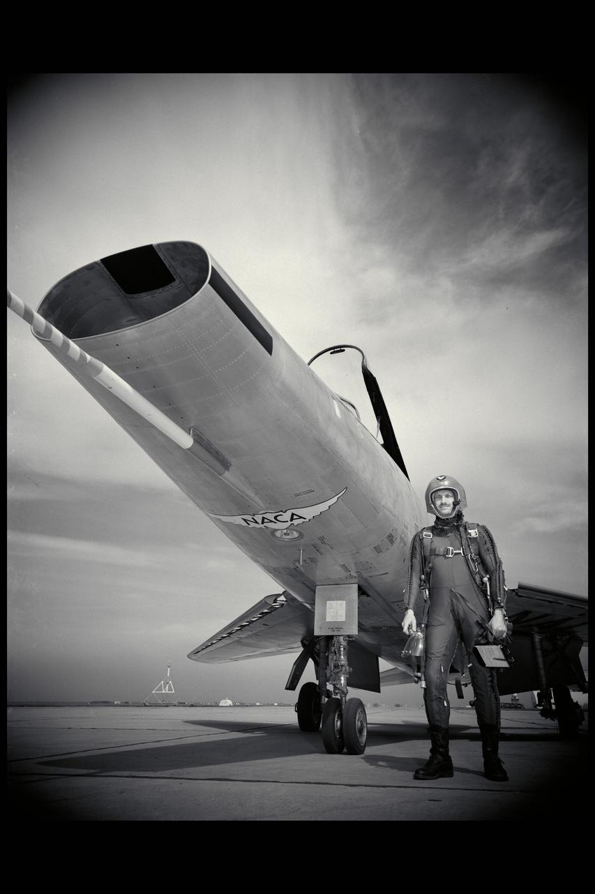
YF-104A (Serial # 55-2961) on Rogers Dry Lake at Edwards AFB.
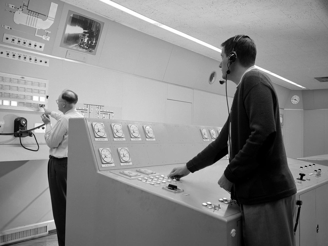
Test engineers monitor an engine firing from the control room of the Rocket Engine Test Facility at the National Advisory Committee for Aeronautics (NACA) Lewis Flight Propulsion Laboratory. The Rocket Engine Test Facility, built in the early 1950s, had a rocket stand designed to evaluate high-energy propellants and rocket engine designs. The facility was used to study numerous different types of rocket engines including the Pratt and Whitney RL-10 engine for the Centaur rocket and Rocketdyne’s F-1 and J-2 engines for the Saturn rockets. The Rocket Engine Test Facility was built in a ravine at the far end of the laboratory because of its use of the dangerous propellants such as liquid hydrogen and liquid fluorine. The control room was located in a building 1,600 feet north of the test stand to protect the engineers running the tests. The main control and instrument consoles were centrally located in the control room and surrounded by boards controlling and monitoring the major valves, pumps, motors, and actuators. A camera system at the test stand allowed the operators to view the tests, but the researchers were reliant on data recording equipment, sensors, and other devices to provide test data. The facility’s control room was upgraded several times over the years. Programmable logic controllers replaced the electro-mechanical control devices. The new controllers were programed to operate the valves and actuators controlling the fuel, oxidant, and ignition sequence according to a predetermined time schedule.

Pilot George Cooper on flightline after test flight holding a dead bird (duck / goose) apparently brought down by his aircraft
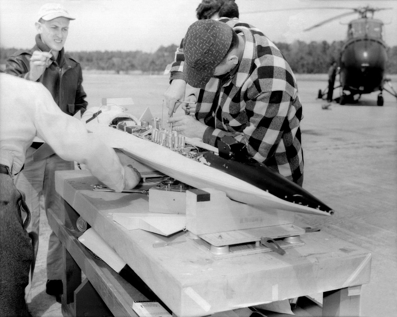
L57-525 Engineer W.J. O Sullivan, Jr., looks at inflated 20 inch subsatellite while holding inflation bottle and folded duplicate copy, February 1957. Photograph published in A New Dimension Wallops Island Flight Test Range: The First Fifteen Years by Joseph Shortal. A NASA publication. Page 601.
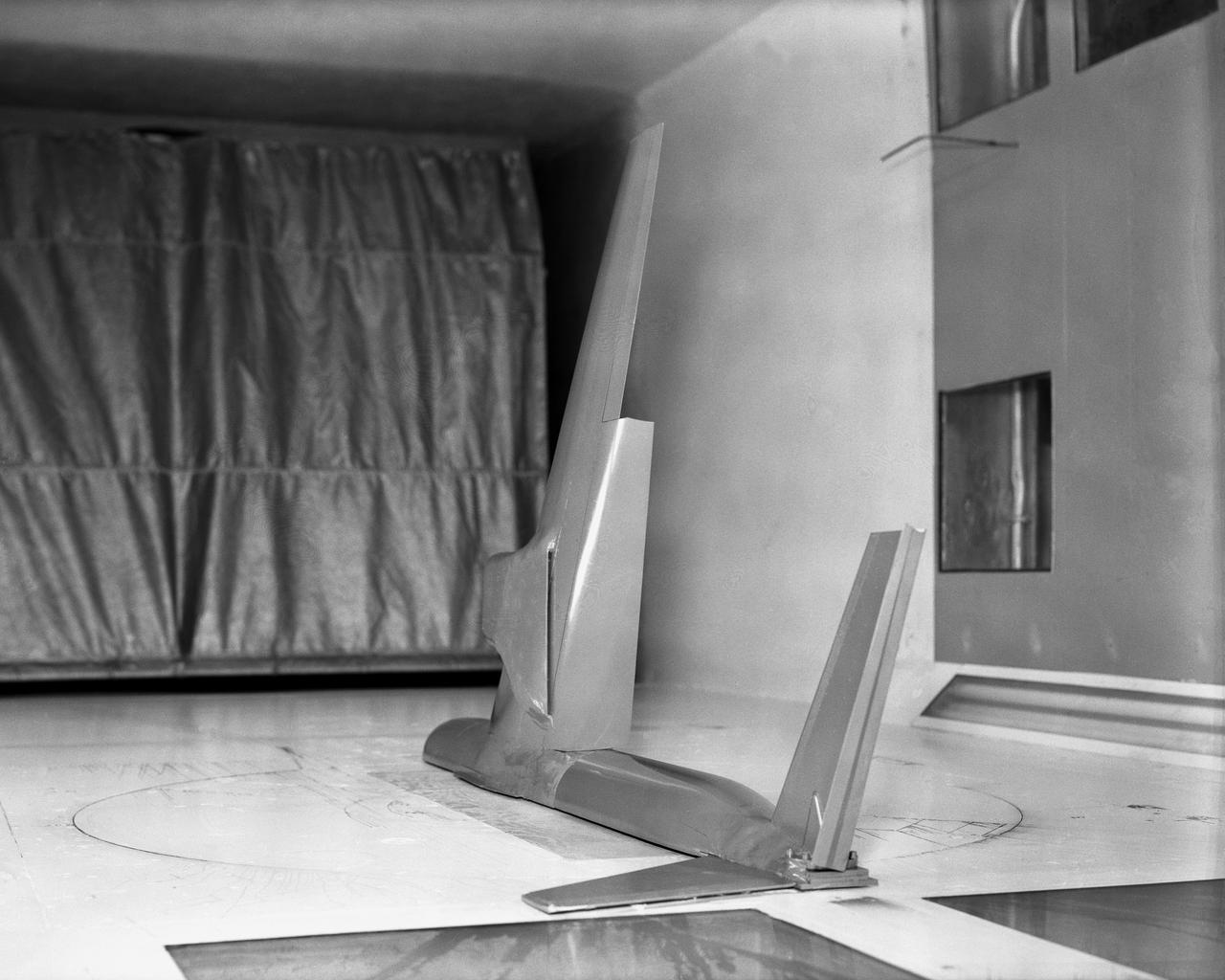
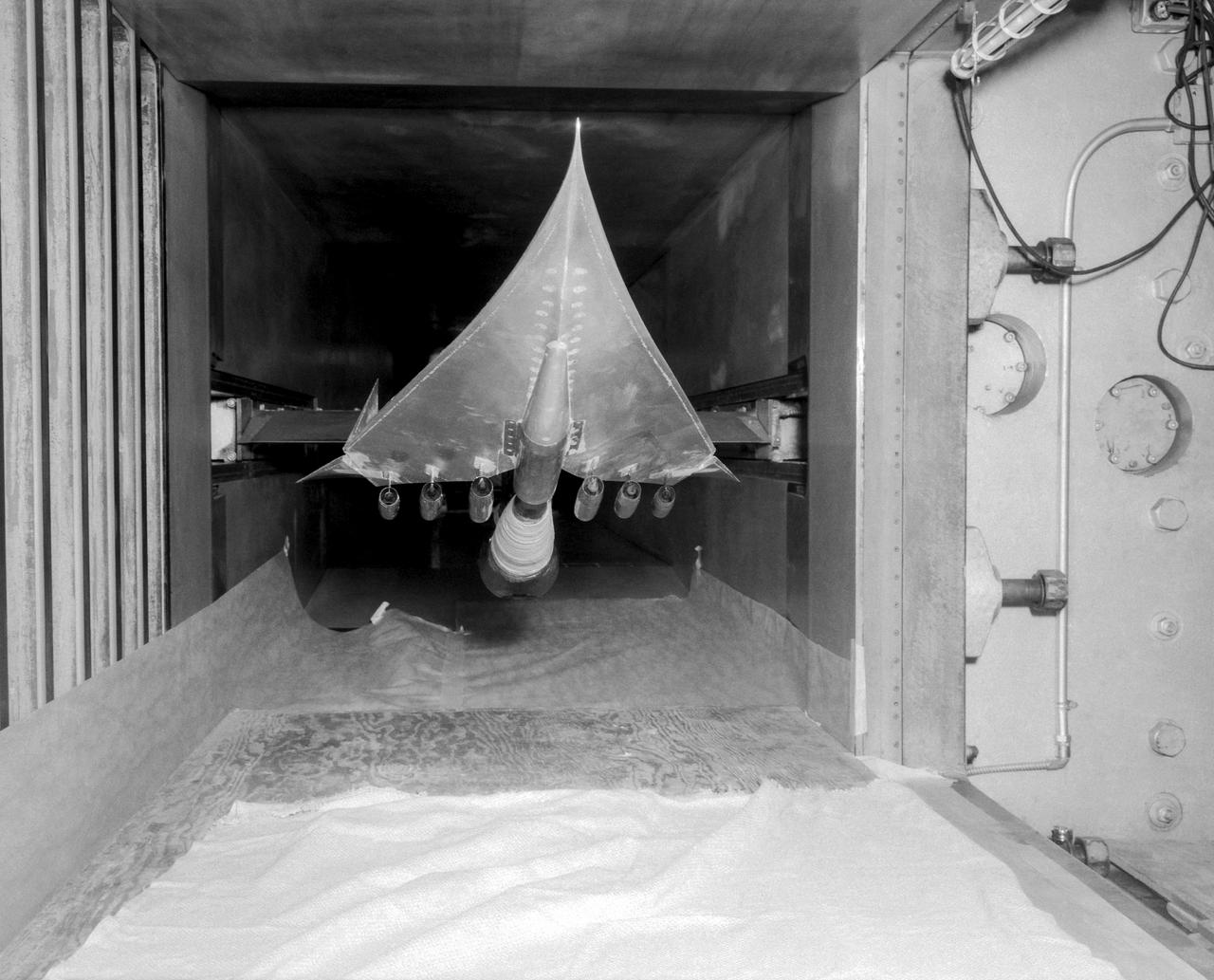
Vertical model flying in Langley Research Center's Full Scale Tunnel.
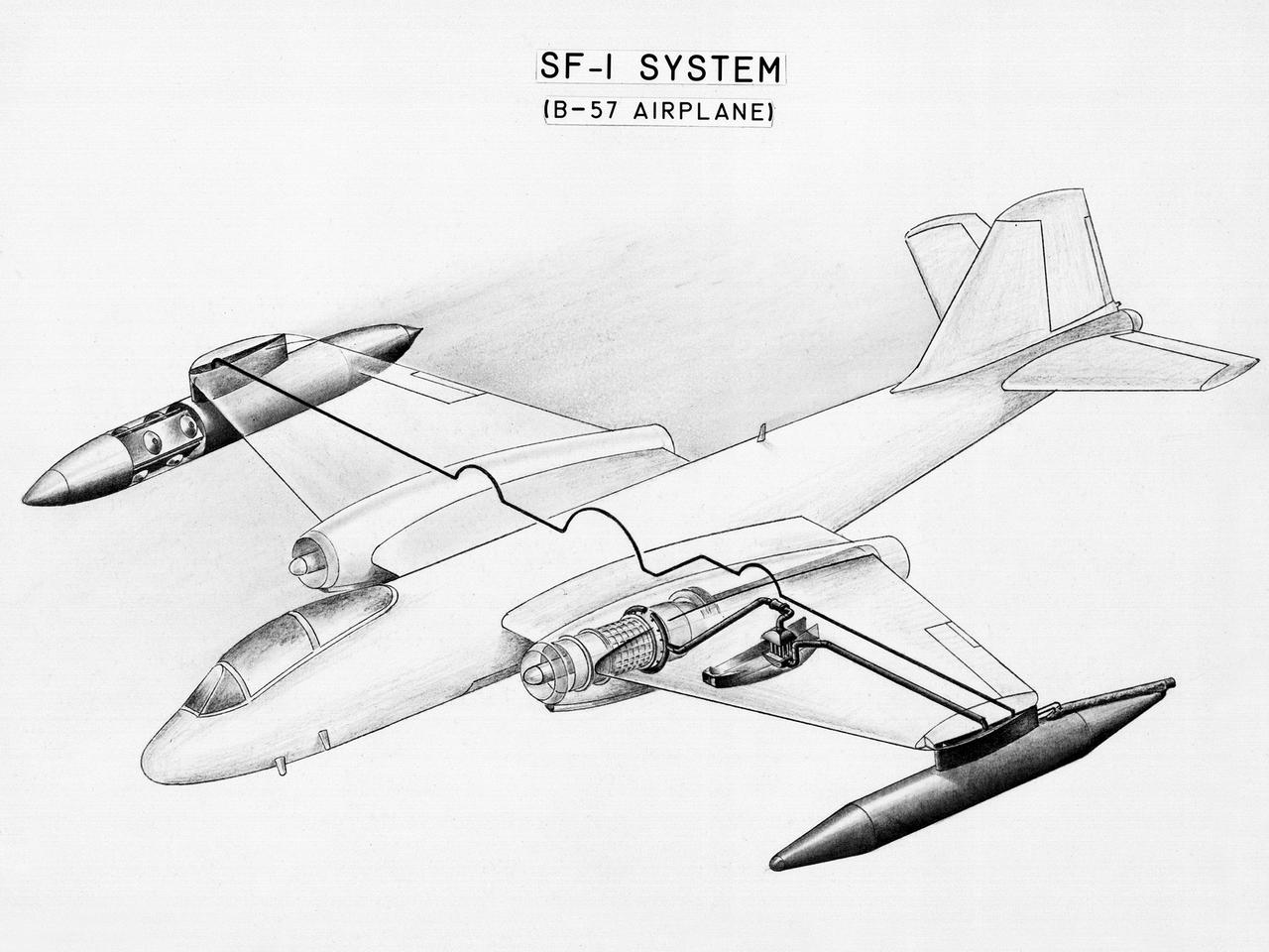
This diagram shows a hydrogen fuel system designed by researchers at the National Advisory Committee for Aeronautics (NACA) Lewis Flight Propulsion Laboratory and installed on a Martin B-57B Canberra aircraft. Lewis researchers accelerated their studies of high energy propellants in the early 1950s. In late 1954, Lewis researchers studied the combustion characteristics of gaseous hydrogen in a turbojet combustor. It was found that the hydrogen provided a very high efficiency. Almost immediately thereafter, Associate Director Abe Silverstein became focused on the possibilities of hydrogen for aircraft propulsion. That fall, Silverstein secured a contract to work with the air force to examine the practicality of liquid hydrogen aircraft. A B-57B Canberra was obtained by the air force especially for this project, referred to as Project Bee. The aircraft was powered by two Wright J65 engines, one of which was modified so that it could be operated using either traditional or liquid hydrogen propellants. The engine and its liquid hydrogen fuel system were tested extensively in the Altitude Wind Tunnel and the Four Burner Area test cells in 1955 and 1956. A B-57B flight program was planned to test the system on an actual aircraft. The aircraft would take off using jet fuel, switch to liquid hydrogen while over Lake Erie, then after burning the hydrogen supply switch back to jet fuel for the landing. The third test flight, in February 1957, was a success, and the ensuing B-57B flights remain the only demonstration of hydrogen-powered aircraft.
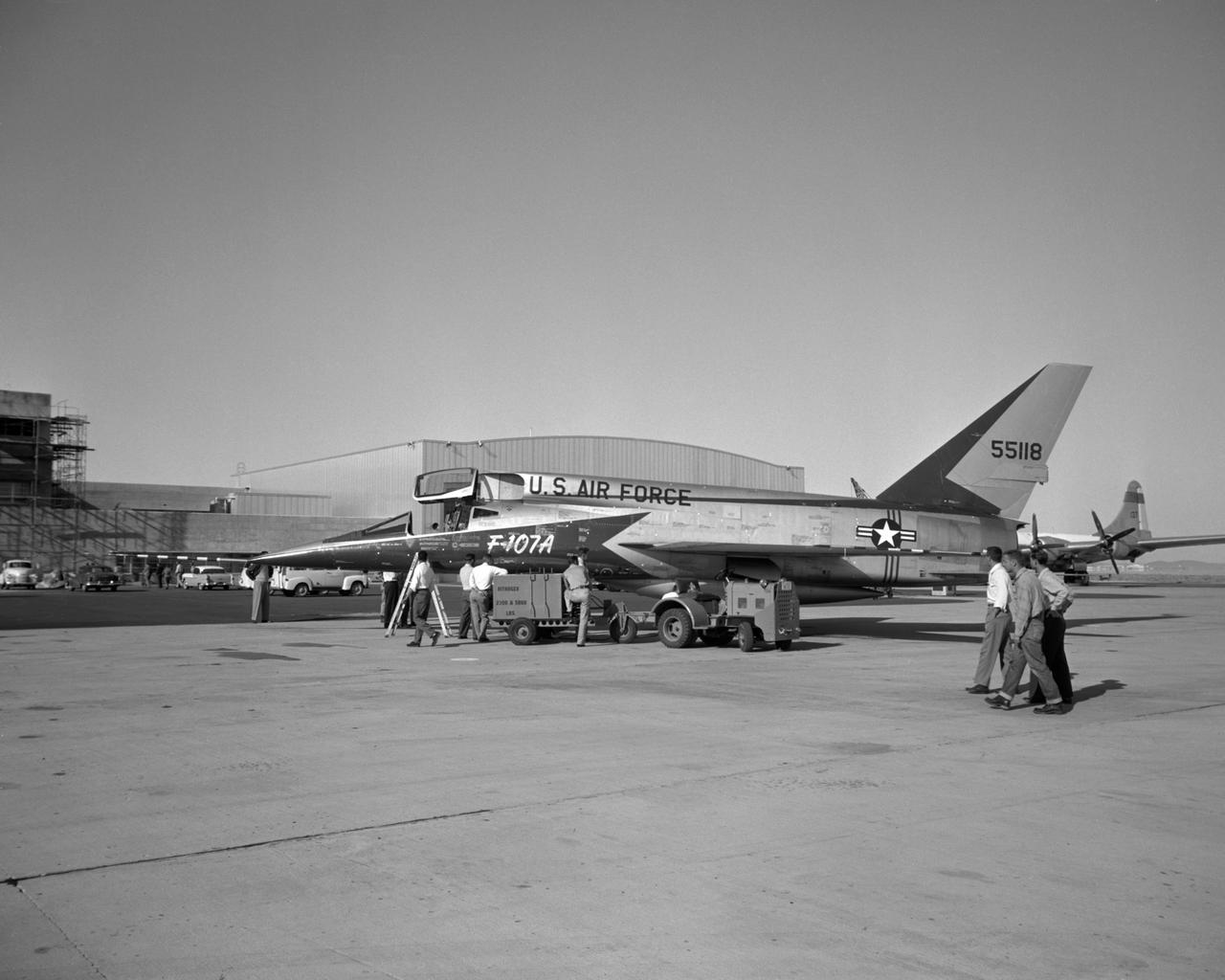
Arrival of first F-107A #118 (later NACA 207) to NASA FRC

E118-2587 Model
North American X-15 Drop Model
Views of F-8U Crusader Aircraft at NASA Langley
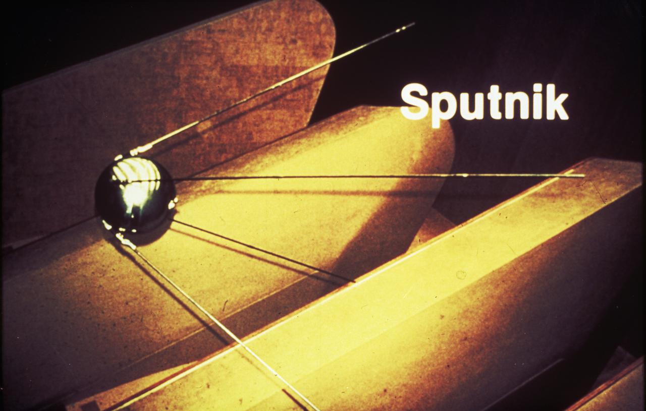
The Army Ballistic Missile Agency incorporated the von Braun team in key positions with Dr. von Braun as a head of the Development Operations Division. On October 4, 1957, the Nation was shocked when the Russians launched Sputnik, the world's first artificial satellite. Two months later, the United States suffered disappointment when a Navy Vanguard rocket, with its satellite payload, failed to develop sufficient thrust and toppled over on the launch pad.
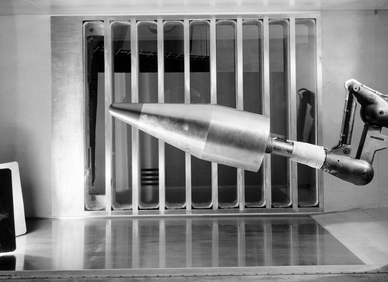
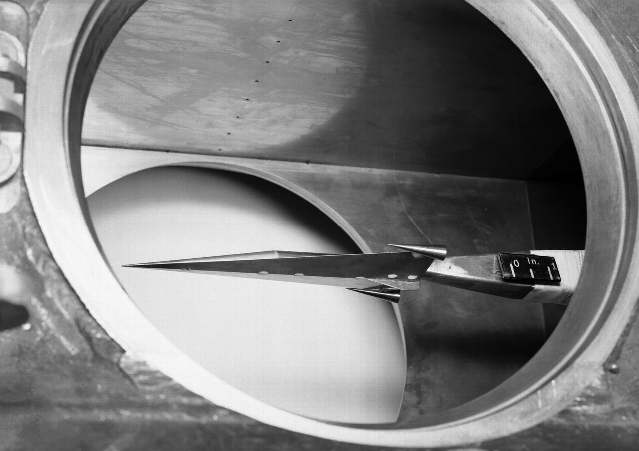
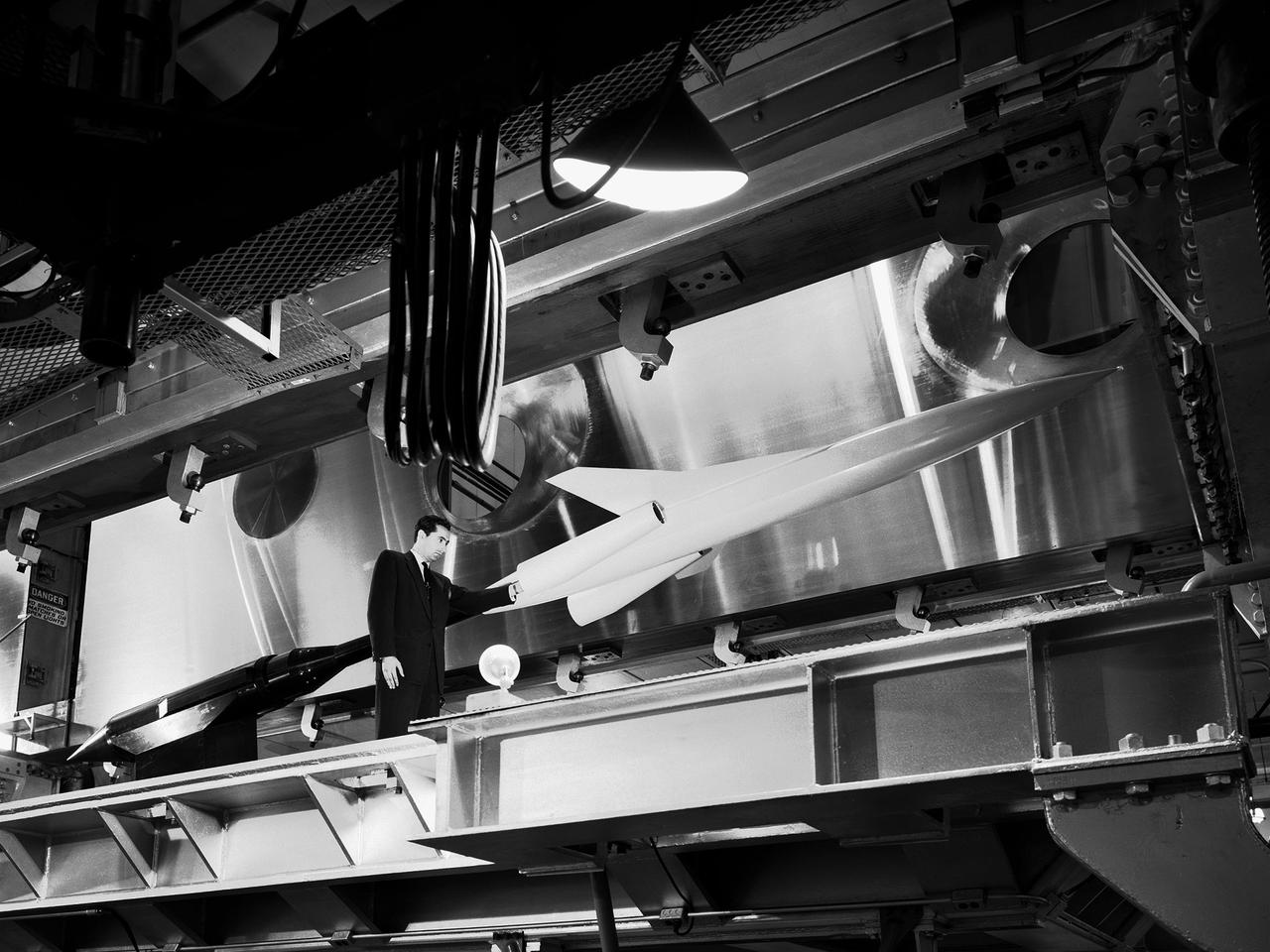
L57-700 In the reentry flight path of this nose cone model of a Jupiter Intermediate range ballistic missile (IRBM) was tested in the Unitary Plan Wind Tunnel. Photograph published in Engineer in Charge: A History of the Langley Aeronautical Laboratory, 1917-1958 by James R. Hansen. Page 475.
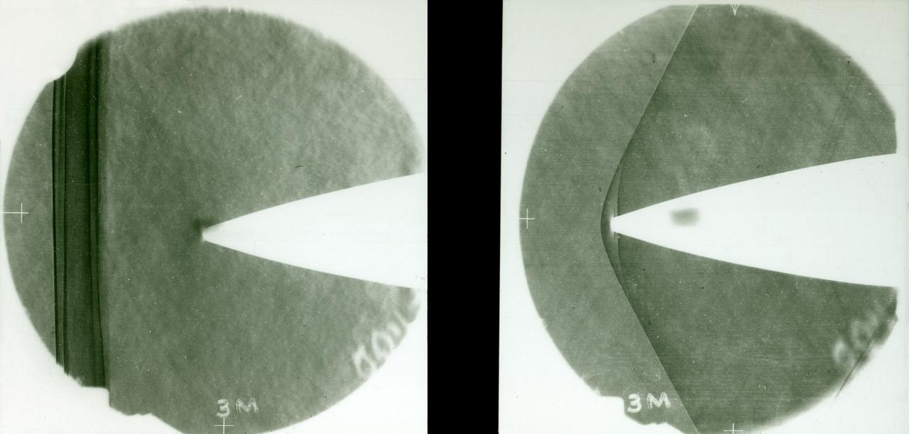
8-Foot Transonic Pressure Tunnel (TPT): Sample of Schlieren results Left - Mach 1.03 Right - Mach 1.20.
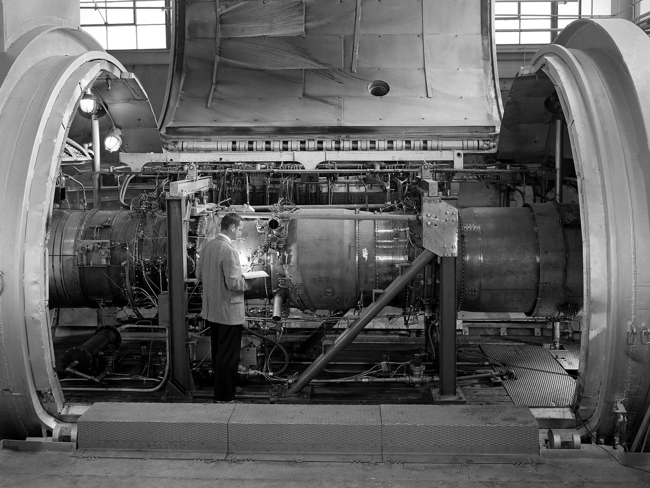
A researcher examines the Orenda Iroquois PS.13 turbojet in a Propulsion Systems Laboratory test chamber at the National Advisory Committee for Aeronautics (NACA) Lewis Flight Propulsion Laboratory. The Iroquois was being developed to power the CF-105 Arrow fighter designed by the Avro Canada Company. Avro began design work on the Arrow jet fighter in 1952. The company’s Orenda branch suggested building a titanium-based PS.13 Iroquois engine after development problems arose with the British engines that Avro had originally intended to use. The 10-stage, 20,000-pound-thrust Iroquois would prove to be more powerful than any contemporary US or British turbojet. It was also significantly lighter and more fuel efficient. An Iroquois was sent to Cleveland in April 1957 so that Lewis researchers could study the engine’s basic performance for the air force in the Propulsion Systems Laboratory. The tests were run over a wide range of speeds and altitudes with variations in exhaust-nozzle area. Initial studies determined the Iroquois’s windmilling and ignition characteristics at high altitude. After operating for 64 minutes, the engine was reignited at altitudes up to the 63,000-foot limit of the facility. Various modifications were attempted to reduce the occurrence of stall but did not totally eradicate the problem. The Arrow jet fighter made its initial flight in March 1958 powered by a substitute engine. In February 1959, however, both the engine and the aircraft programs were cancelled. The world’s superpowers had quickly transitioned from bombers to ballistic missiles which rendered the Avro Arrow prematurely obsolete.
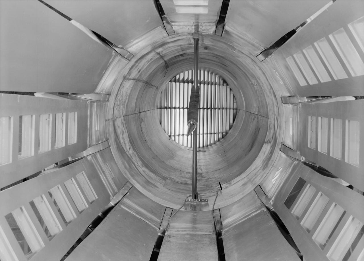
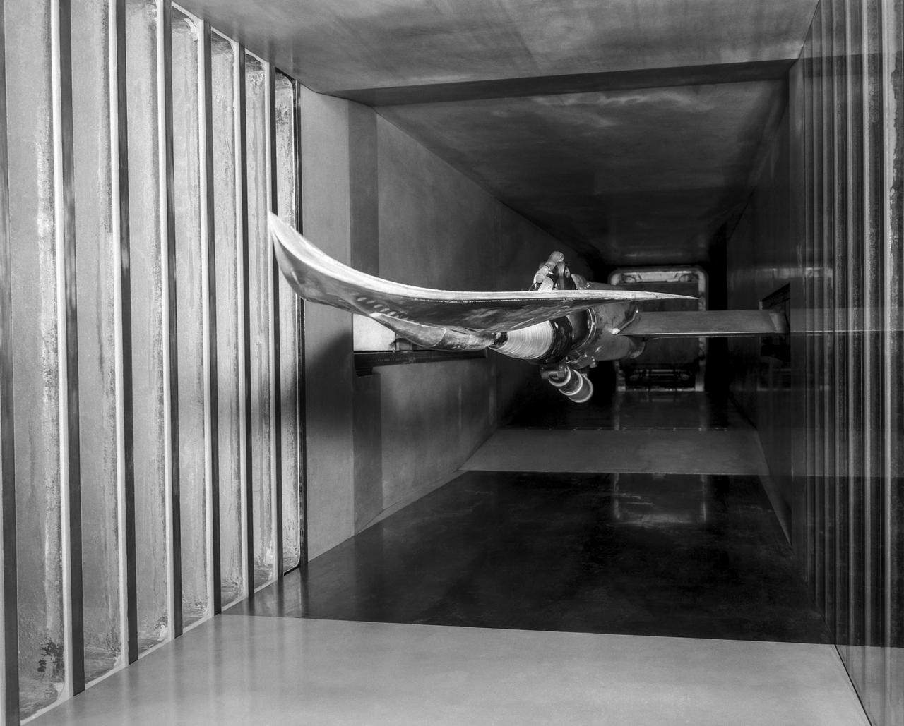
Interior view of the slotted throat test section installed in the 8-Foot High Speed Tunnel (HST) in 1950. The slotted region is about 160 inches in length. In this photograph, the sting-type model support is seen straight on. In a NASA report, the test section is described as follows: The test section of the Langley 8-foot transonic tunnel is dodecagonal in cross section and has a cross-sectional area of about 43 square feet. Longitudinal slots are located between each of the 12 wall panels to allow continuous operation through the transonic speed range. The slots contain about 11 percent of the total periphery of the test section. Six of the twelve panels have windows in them to allow for schlieren observations. The entire test section is enclosed in a hemispherical shaped chamber. John Becker noted that the tunnel s final achievement was the development and use in routine operations of the first transonic slotted throat. The investigations of wing-body shapes in this tunnel led to Whitcomb s discovery of the transonic area rule. James Hansen described the origins of the the slotted throat as follows: In 1946 Langley physicist Ray H. Wright conceived a way to do transonic research effectively in a wind tunnel by placing slots in the throat of the test section. The concept for what became known as the slotted-throat or slotted-wall tunnel came to Wright not as a solution to the chronic transonic problem, but as a way to get rid of wall interference (i.e., the mutual effect of two or more meeting waves or vibrations of any kind caused by solid boundaries) at subsonic speeds. For most of the year before Wright came up with this idea, he had been trying to develop a theoretical understanding of wall interference in the 8-Foot HST, which was then being repowered for Mach 1 capability. When Wright presented these ideas to John Stack, the response was enthusiastic but neither Wright nor Stack thought of slotted-throats as a solution to the transonic problem, only the wall interference problem. It was an accidental discovery which showed that slotted throats might solve the transonic problem. Most engineers were skeptical but Stack persisted. Initially, plans were to modify the 16-Foot tunnel but in the spring of 1948, Stack announced that the 8-Foot HST would also be modified. As Hansen notes: The 8-Foot HST began regular transonic operations for research purposes on 6 October 1950. The concept was a success and led to plans for a new wind tunnel which would be known as the 8-Foot Transonic Pressure Tunnel. -- Published in U.S., National Advisory Committee for Aeronautics, Characteristics of Nine Research Wind Tunnels of the Langley Aeronautical Laboratory, 1957, pp. 17, 22 James R. Hansen, Engineer in Charge, NASA SP-4305, p. 454 and Chapter 11, The Slotted Tunnel and the Area Rule.
Hypersonic Boost Glider in 11 Inch Hypersonic Tunnel L57-1681 In 1957 Langley tested its HYWARDS design in the 11 Inch Hypersonic Tunnel. Photograph published in Engineer in Charge: A History of the Langley Aeronautical Laboratory, 1917-1958 by James R. Hansen. Page 369.
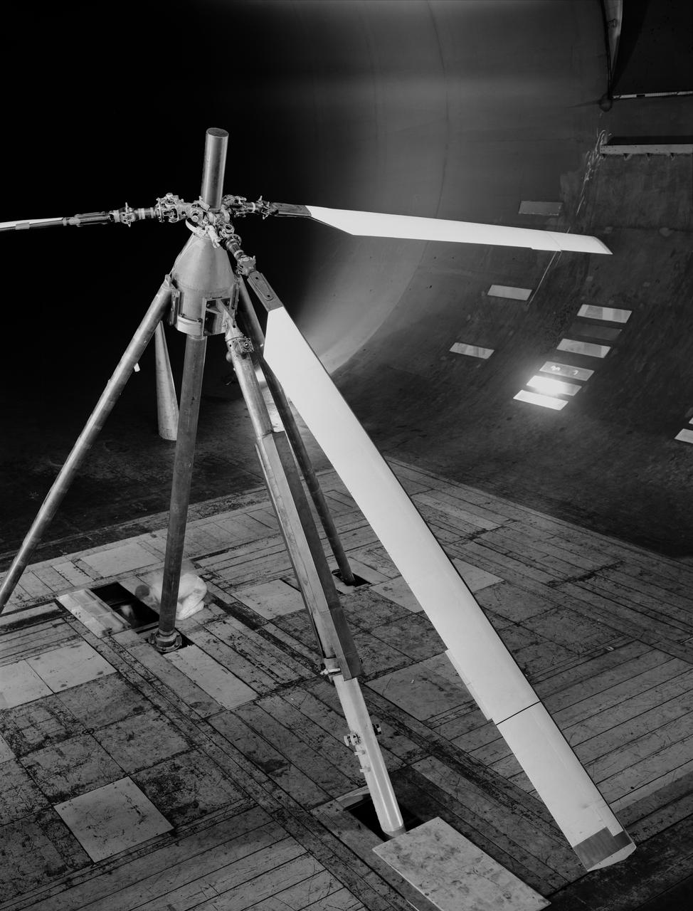
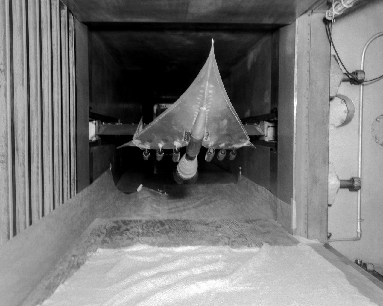
Experimental investigation of boundary layer control to helicopter rotor blades to increase forward speed capabilities. 3/4 overhead view. Shaft angle - 35deg.
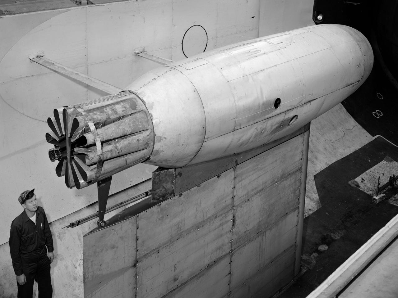
A Pratt and Whitney J57 engine is tested with a Greatex No.1 nozzle in the Altitude Wind Tunnel at the National Advisory Committee for Aeronautics (NACA) Lewis Flight Propulsion Laboratory. At the time the aircraft industry was preparing to introduce jet airliners to the nation’s airways. The noise produced by the large jet engines, however, posed a considerable problem for communities near airports. The NACA had formed a Special Subcommittee on Aircraft Noise to coordinate research on the issue. Preliminary tests showed that the source of the loudest noise was not the engine itself, but the mixing of the engine’s exhaust with the surrounding air in the atmosphere. The pressures resulting from this turbulence produced sound waves. Lewis researchers undertook a variety of noise-reduction studies involving engine design, throttling procedures, and noise suppressors. One of their first efforts focused on new types of nozzles to mix the exhaust with the surrounding air. The nozzles had a variety of shapes designed to slow down exhaust velocity before it combined with the air and thus decrease the noise. From January to May 1957 a Pratt and Whitney J57 engine was equipped with various shaped nozzles, as seen in this photograph, and run in simulated flight conditions in the Altitude Wind Tunnel. A number of nozzle configurations, including several multi-exit “organ pipe” designs, were created. It was found that the various nozzle types did reduce the noise levels, but they also reduced the aircraft’s thrust.
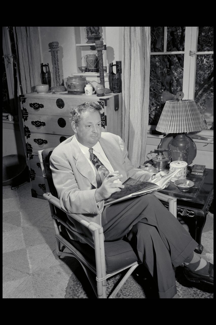
Harvey Allen, Chief of the High-Speed Research Division at NASA Ames Research Center, in his home.
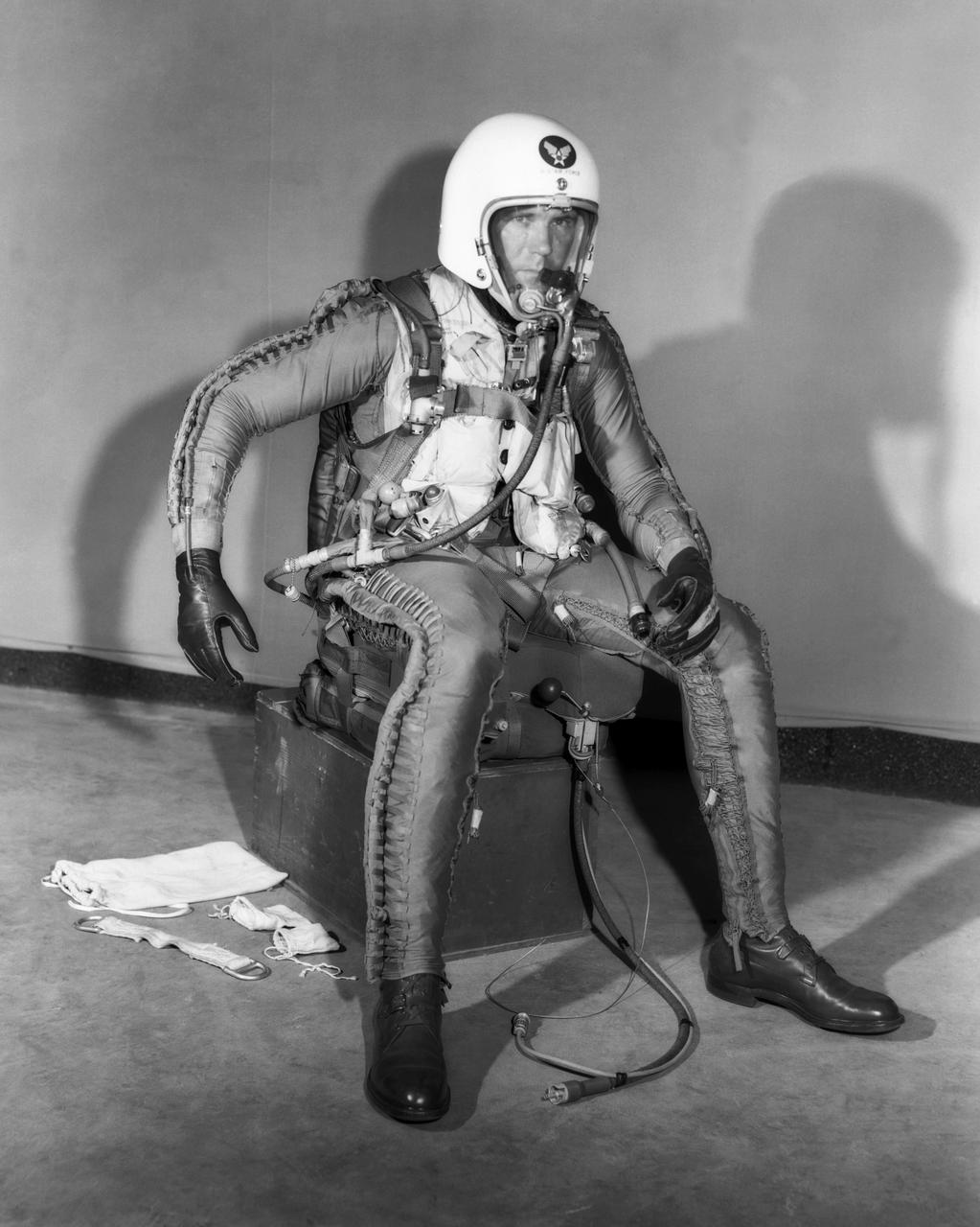
Robert Champine in X-Series Pressure Suit. Photograph published in Engineer in Charge: A History of the Langley Aeronautical Laboratory, 1917-1958 by James R. Hansen. Page 305.
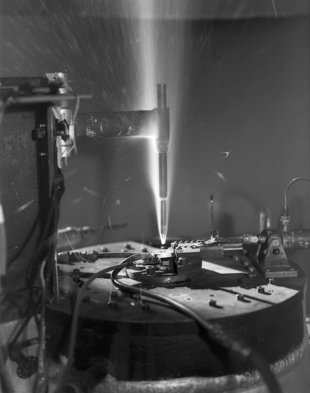
L57-5383 Hot-air jets employing ceramic heat exchangers played an important role at Langley in the study of materials for ballistic missile nose cones and re-entry vehicles. Here a model is being tested in one of theses jets at 4000 degrees Fahrenheit in 1957. Photograph published in Engineer in Charge: A History of the Langley Aeronautical Laboratory, 1917-1958 by James R. Hansen. Page 477.

Water Type Muffler Test

NACA/Ames Photographer Radio personality Arthur Godfrey shown here with Ames Pilot George Cooper and Center Director Smith J DeFrance during tour of facility
WS-110A "Brown Bomber"
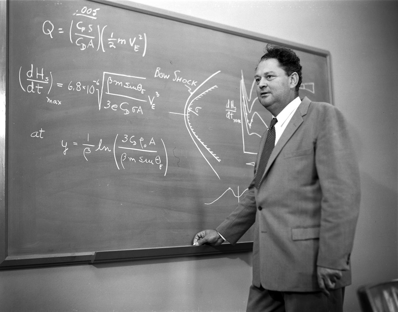
Portrait of NASA Ames Engineer H. Julian 'Harvey' Allen explaining blunt nose principle.

Water Type Muffler Test
WS-110A "Brown Bomber"
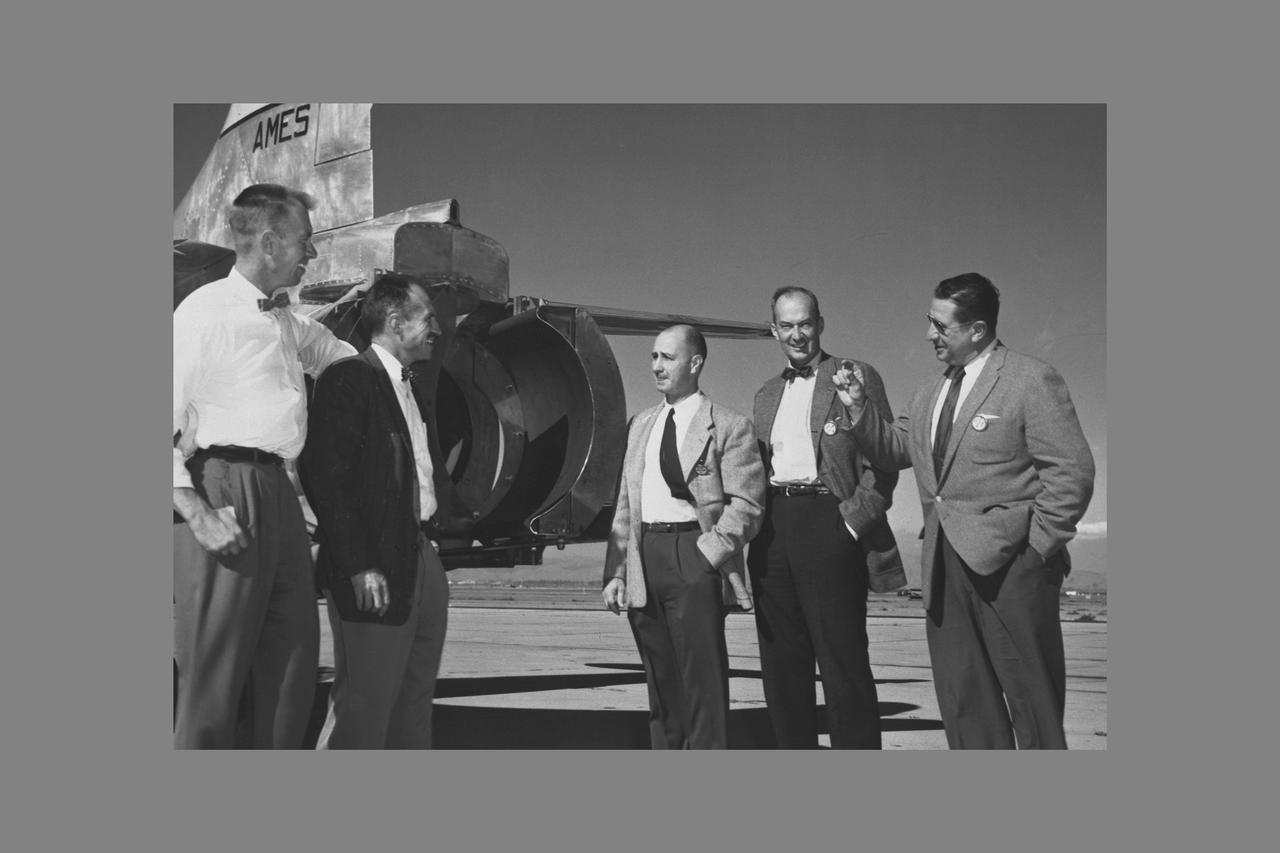
NACA AMES ENGINEERS: Seth B. ANDERSON AND NACA AMES PILOT Gorge E. COOPER WITH W.E. RHOADES, ROBERT McIVER, MICHAEL CASSENLY OF UNITED AIRLINES. Visit Ames to dicuss Thrust Reverser Problems.

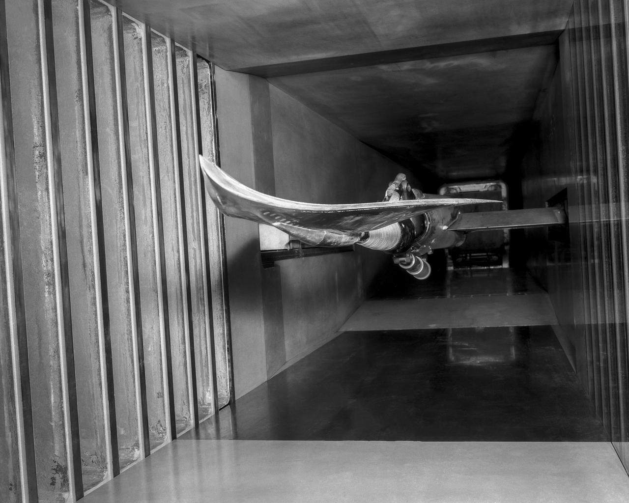
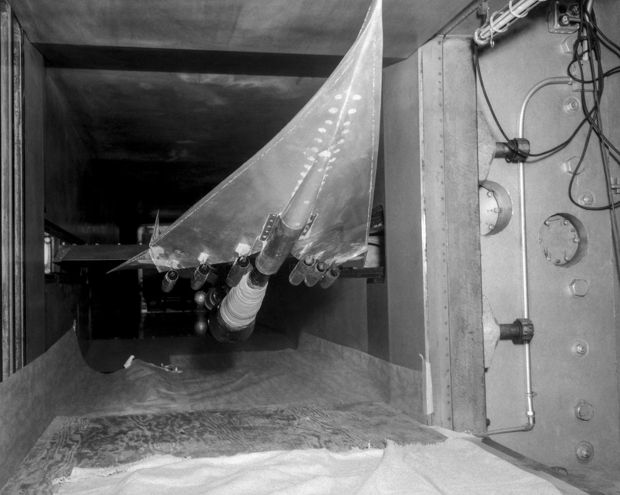
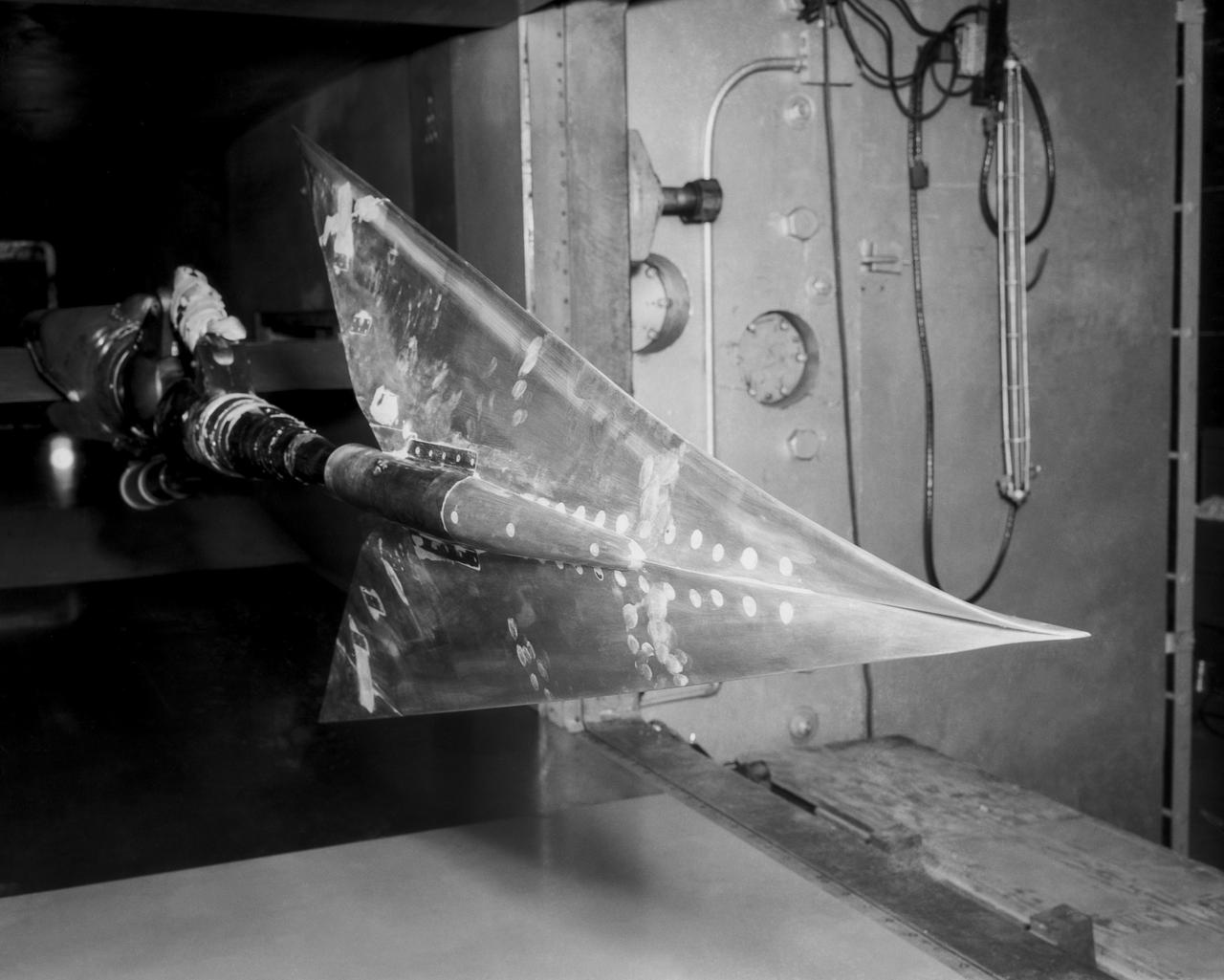
Application of blowing-type boundry-layer control to the leading-and trailing-edge flaps of a Change Vought XF8U-1 wing

17-foot test section in contraction cone of 300-MPH 7 x 10-Foot Tunnel (7 x 10-Foot test section in background).
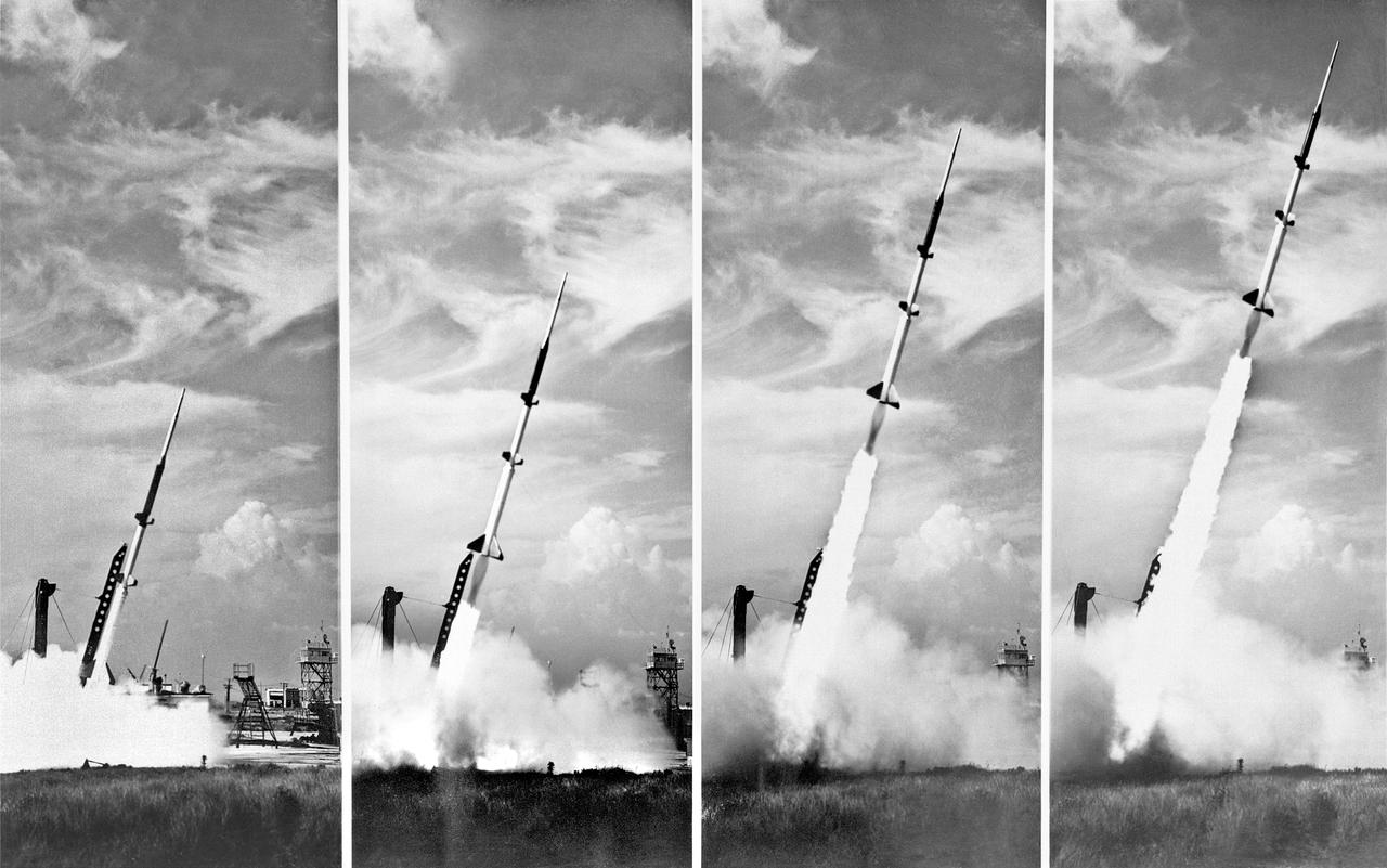
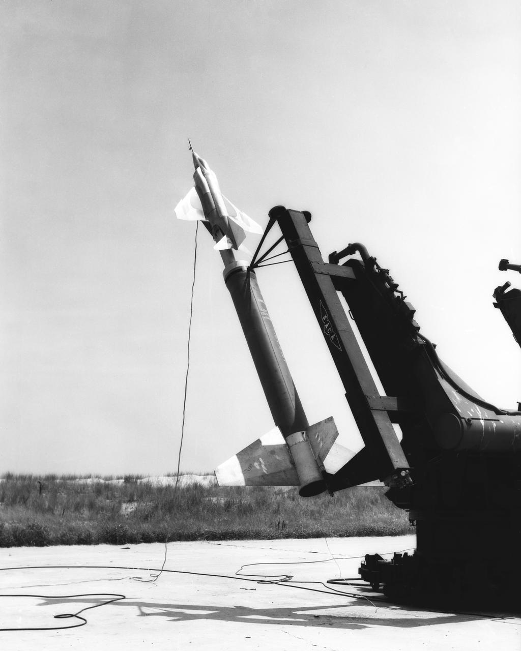
**Note also copied and numbered as L90-3749. -- L57-4827 caption: Take off of a five-stage missile research rocket from Wallops Island in 1957. The first two stages propelled the model to about 100,000 feet the last three stages were fired on a descending path to simulate the reentry conditions of ballistic missiles. -- Photograph published in Winds of Change, 75th Anniversary NASA publication (page 72), by James Schultz. -- Photograph also published in Engineer in Charge: A History of the Langley Aeronautical Laboratory, 1917-1958 by James R. Hansen (page 380).

Water Type Muffler Test
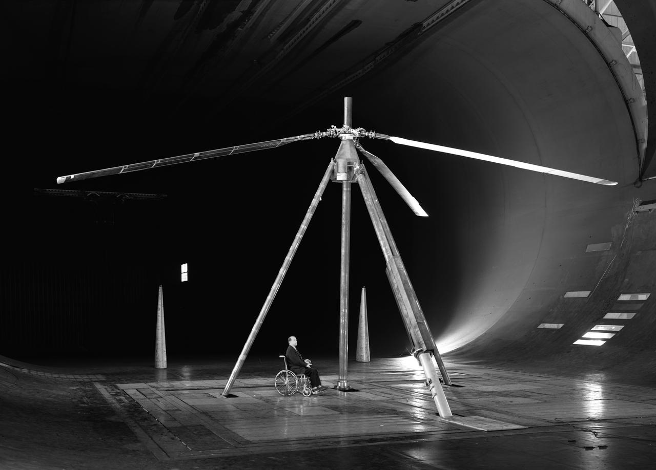
Experimental investigation of boundary-layer control to helicopter rotor blades to increase forward speed capabilities. 3/4 front view. Shaft angle - 35deg. John Mc.Cloud in picture. He was a good guy.
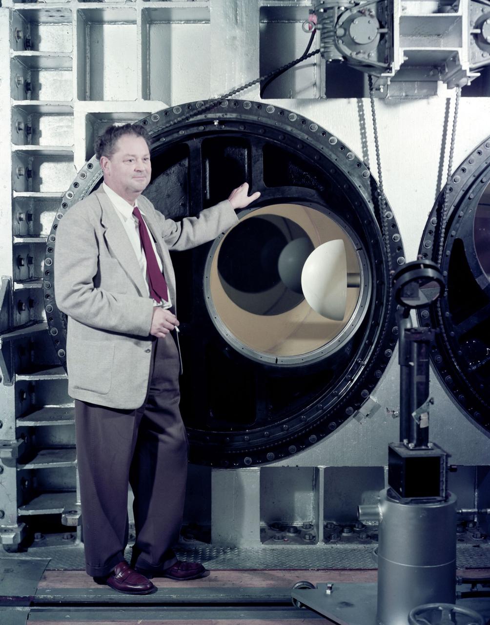
A researcher examines a model being installed in the test section of the 10- by 10-Foot Supersonic Wind Tunnel during the 1957 Inspection of the National Advisory Committee for Aeronautics (NACA) Lewis Flight Propulsion Laboratory. The NACA held its annual Inspection at one of its three research laboratories. Representatives from the military, aeronautical industry, universities, and the press were invited to the laboratory to be briefed on the NACA’s latest research efforts and tour the state- of- the- art test facilities. Over 1700 people visited the NACA Lewis in Cleveland, Ohio during the October 7 - 10, 1957 Inspection. NACA researchers Leonard Obery, seen here, James Connors, Leonard, Stitt, David Bowditch gave presentations on high Mach number turbojets at the 10- by 10 tunnel. It had been only 15 years since a jet aircraft had first flown in the US. Since then the sound barrier had been broken and speeds of Mach 2.5 had been achieved. In the late 1950s NACA researchers sought to create an engine that could achieve Mach 4. This type of engine would require an extremely long inlet and nozzle which would have to be capable of adjusting their diameter for different speeds. A Mach 4 engine would require new composite materials to withstand the severe conditions, modified airframes to hold the longer engines, and high temperature seals and lubricants. The 10- by 10-foot tunnel, which had only been in operation for a year and a half, would play a critical role in these studies. NACA researchers at other facilities discussed high energy aircraft fuels and rocket propellants, aircraft noise reduction, hypersonic flight, nuclear propulsion, and high temperature materials.
General Research Model in 300 MOH 7x10
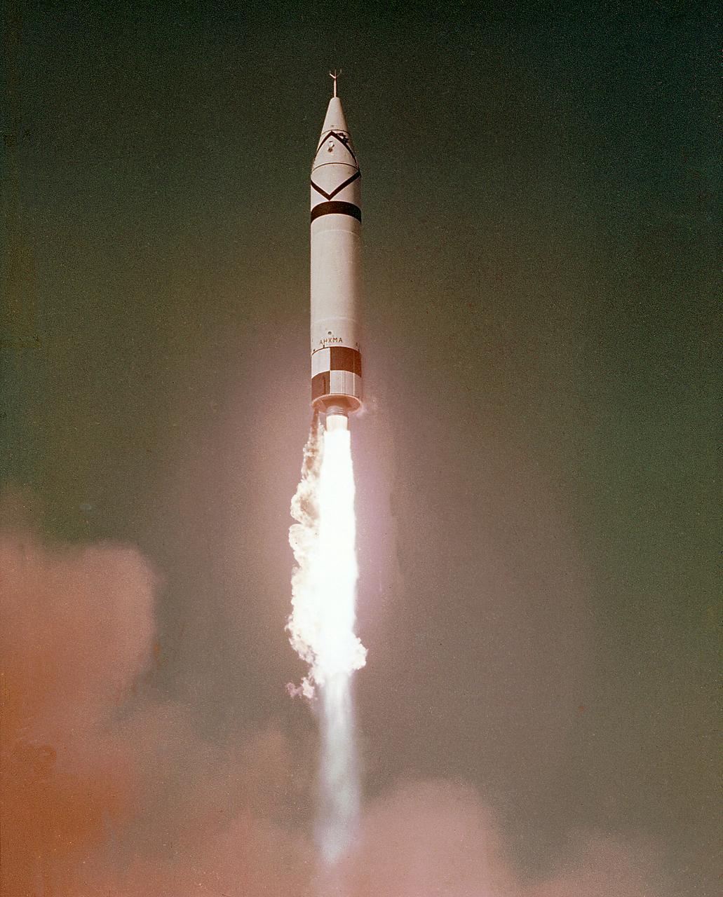
The Jupiter rocket was designed and developed by the Army Ballistic Missile Agency (ABMA). ABMA launched the Jupiter-A at Cape Canaveral, Florida, on March 1, 1957. The Jupiter vehicle was a direct derivative of the Redstone. The Army Ballistic Missile Agency (ABMA) at Redstone Arsenal, Alabama, continued Jupiter development into a successful intermediate ballistic missile, even though the Department of Defense directed its operational development to the Air Force. ABMA maintained a role in Jupiter RD, including high-altitude launches that added to ABMA's understanding of rocket vehicle operations in the near-Earth space environment. It was knowledge that paid handsome dividends later.
H. Julian 'Harvey' Allen in front of the NASA Ames 8_x_7 foot Supersonic Wind Tunnel test section. A blunt body model mounted in the test section is ready for testing . The 8_X_7_foot is part of the Unitary Plan WInd Tunnel Complex Note: printed in 60 year at NASA Ames Research Center by Glenn Bugos NASA SP-2000-4314
WS-110A "Brown Bomber"

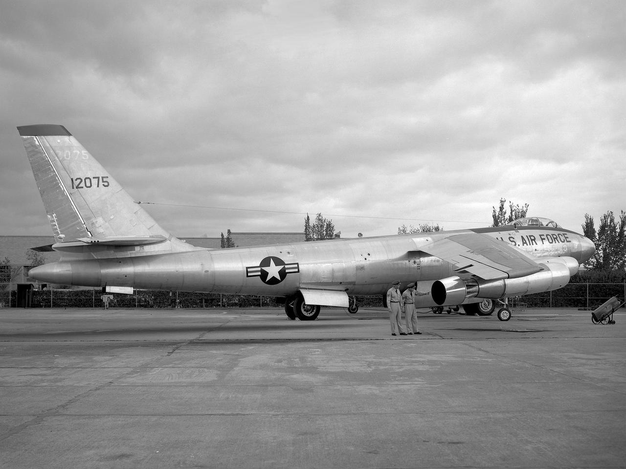
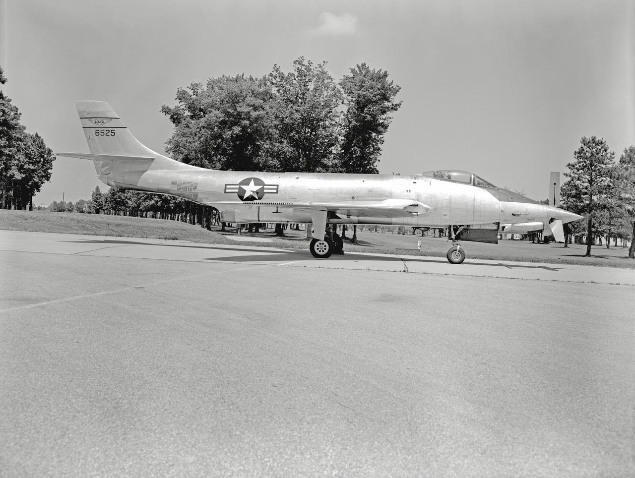
McDonnell F2H-3 Banshee: To more clearly mark the operators of this McDonnell F2H-3 Banshee, the VY of Navy has been painted out and the appropriate lettering to spell NACA has been applied. Note that the second A is of a different shape than the first. The Banjo retained Navy titles on the wings, however.
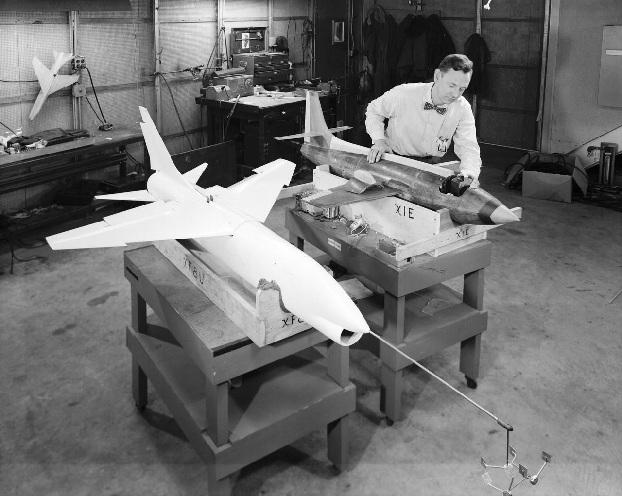
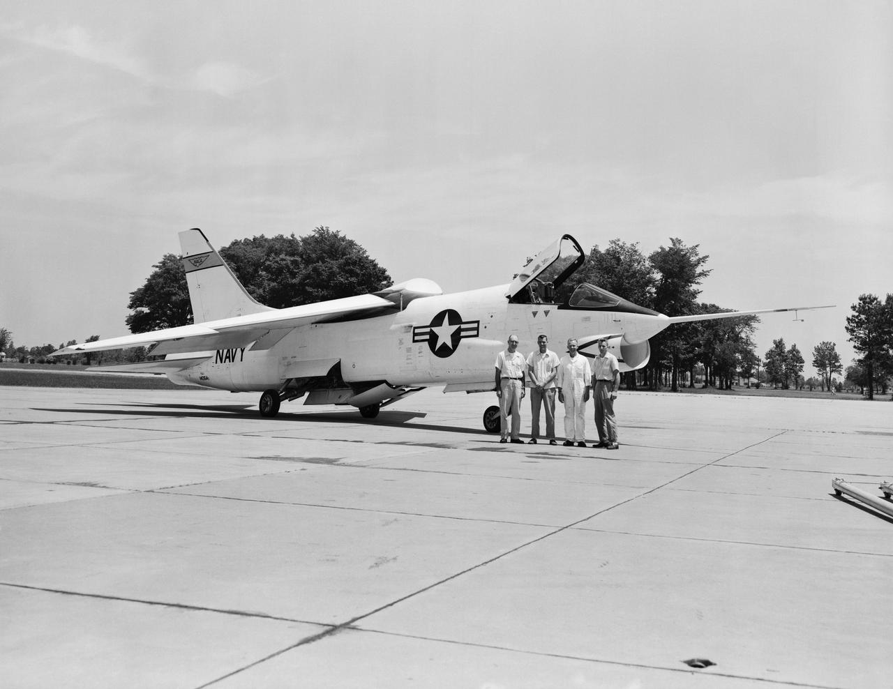
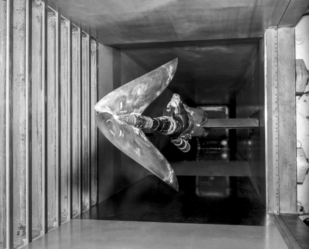
L57-660 A technician prepares dynamic models of the Bell X-1E and the Vought XF-8U Crusader for wind tunnel testing in 1957. The Crusader was then the Navy's fastest aircraft- maximum speed Mach 1.75 at 35,000 Feet. Photograph published in Engineer in Charge: A History of the Langley Aeronautical Laboratory, 1917-1958 by James R. Hansen. Page 307.
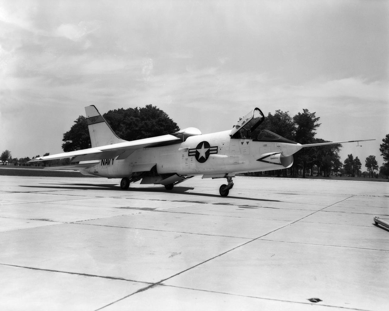
Views of F-8U Crusader Aircraft at NASA Langley
A Boeing B-47 Stratojet bomber with a noise-reducing ejector on its engine at the 1957 Inspection of the National Advisory Committee for Aeronautics (NACA) Lewis Flight Propulsion Laboratory. Representatives from the military, aeronautical industry, universities, and the press were invited to the laboratory to be briefed on the NACA’s latest research efforts and tour the state- of- the- art test facilities. Over 1700 people visited the NACA Lewis in Cleveland, Ohio during October 7 - 10, 1957. By the mid-1950s, the aircraft industry was close to introducing jet airliners to the nation’s airways. The noise produced by the large jet engines, however, would pose a considerable problem for communities near airports. This problem was demonstrated at the 1957 Inspection by an NACA Lewis researcher who played longplay (LP) audio records of military jet engines for an audience. Tests showed that the source of the loudest noise was not the engine itself, but the mixing of the engine’s exhaust with the surrounding air in the atmosphere. The pressures resulting from this turbulence produced sound waves. One of Lewis’ first studies sought to design an exhaust nozzle that reduced the turbulence. A Pratt and Whitney J57 was tested in the Altitude Wind Tunnel with many of these nozzle configurations from January to May 1957. Researchers found that the various nozzle types did reduce the noise levels but also reduced the aircraft’s thrust. Afterwards, they determined that the addition of an NACA-developed ejector reduced the noise levels without diminishing thrust.
IBM 704 Computer Operations People on the photo are: Woman in the front with her back to the camera is Jean Ruddle Migneault. She provided the names for the rest of the staff in the photo. Kathy Christian Young, Mary Talmage Kaylor, Willie Terrell Ruffin (computer operator not mathematician), Joyce Alston Clemens, Lou Mayo Ladson, Rachel Richardson Mayo, Sadie Livingston Boyer , Joann Shipp Buschman worked in hangar in West Area, Shelva Blevins Stroud (programmer in data reduction), Jackie Kilby, Rita Englebert, Harriet Seals Winestein, Lillian Boney, Jane Thompson Kemper, Helen Thompson ( math aide) Jane and Helen were daughters of Floyd Thompson, center director.
Phase SB Propeller installed on F88B
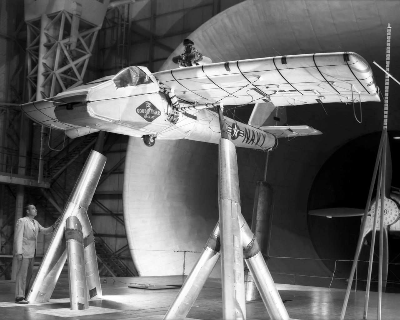
Various views of the Goodyear Inflate-A-Plane mounted in Full Scale Tunnel.
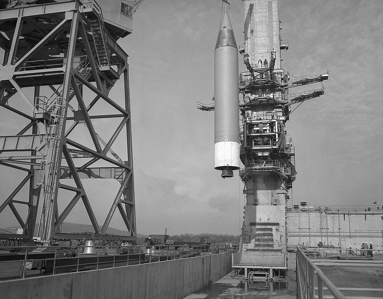
Installation of a Jupiter Missile in ABMA (Army Ballistic Missile Agency) West Test Stand, Jan. 16, 1957. Jupiter was a 1500-mile range missile
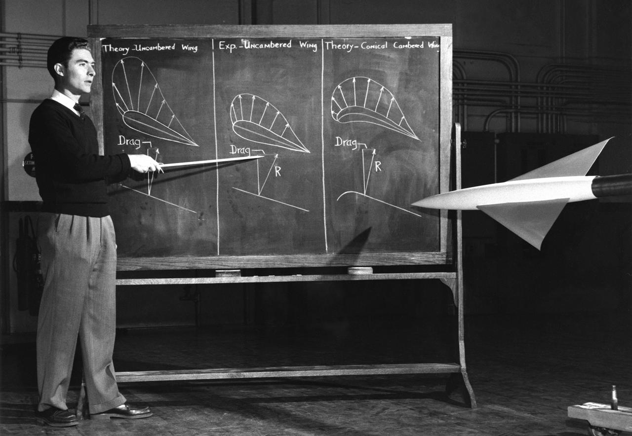
NACA Photographer John W. Boyd explaining the efficiencies of conical camber
WS-110A "Brown Bomber"
North American X-15 Drop Model
Phase SB Propeller installed on F88B
WS-110A "Brown Bomber"
America’s first scientific satellite, the Explorer I, carried the radiation detection experiment designed by Dr. James Van Allen and discovered the Van Allen Radiation Belt. It was launched aboard a modified redstone rocket known as the Jupiter C, developed by Dr. von Braun’s rocket team at Redstone Arsenal in Huntsville, Alabama. The satellite launched on January 31, 1958, just 3 months after the the von Braun team received the go-ahead.
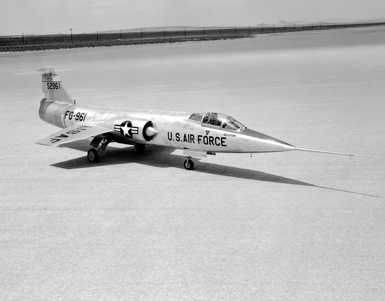
YF-104A (Serial #55-2961) on Rogers Dry Lake at Edwards AFB.
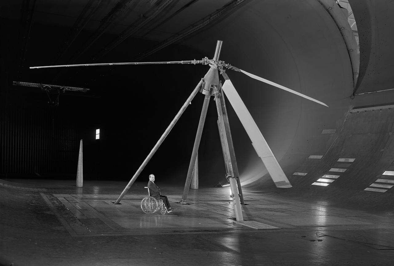
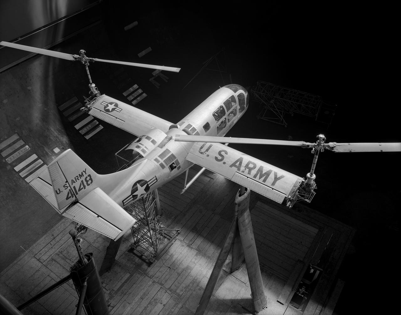
One of the first helicopter tests in the 40 x 80 wind tunnel. John McCloud, pictured, started helicopter work in the 40 x 80. Test 150. Testing the effects of camber on rotor blades.
8-Foot Transonic Pressure Tunnel (TPT): Sample of Schlieren results Left - Mach 1.03 Right - Mach 1.20.

Water Type Muffler Test
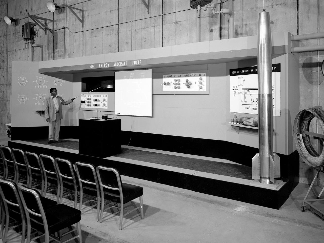
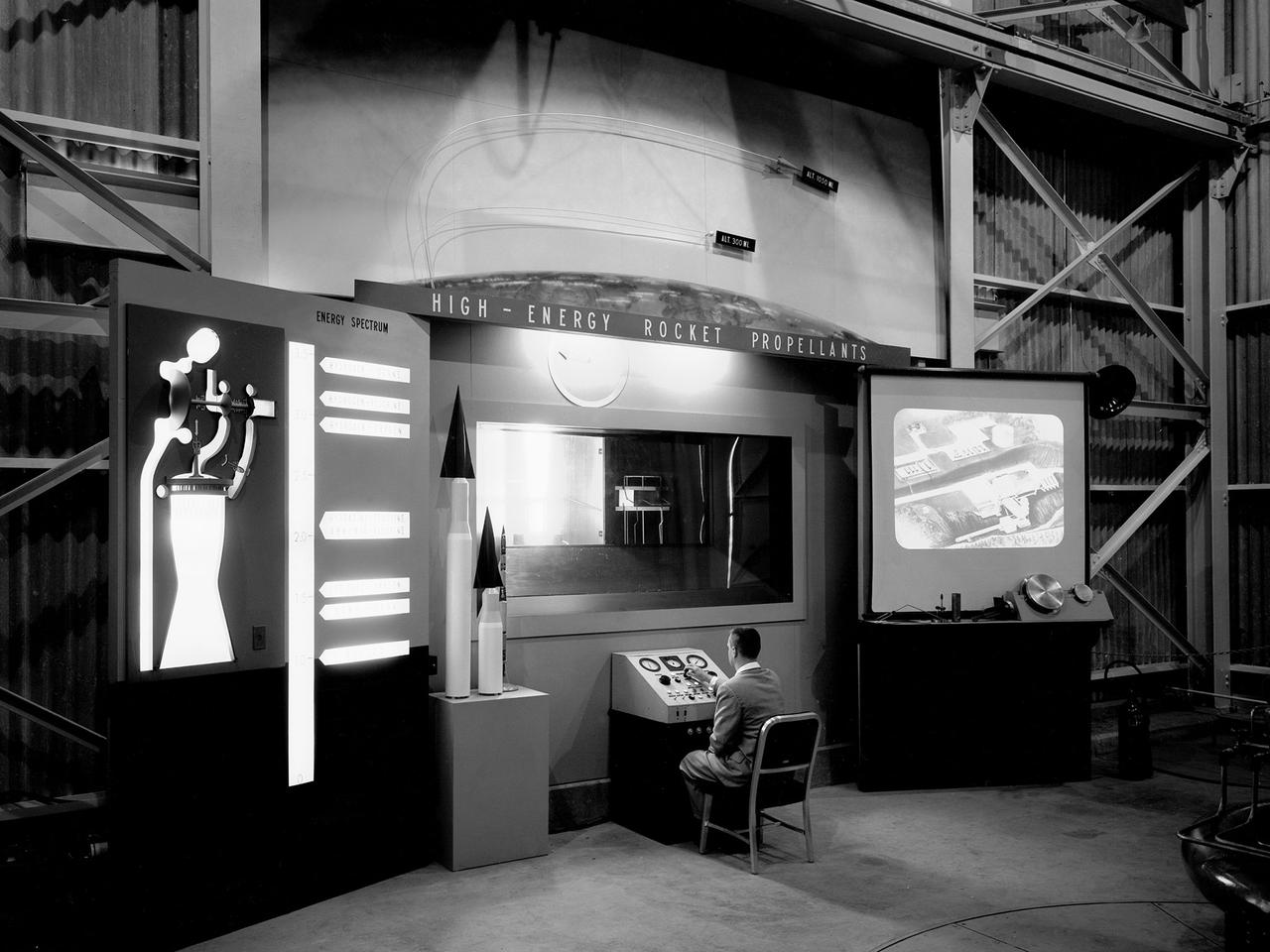
A researcher operates a demonstration board regarding high-energy propellants during the 1957 Inspection of the NACA’s Lewis Flight Propulsion Laboratory in Cleveland, Ohio. Representatives from the military, aeronautical industry, universities, and the press were invited to the laboratory to be briefed on the NACA’s latest research efforts and tour the test facilities. Over 1700 people visited the Lewis during the October 7-10, 1957 Inspection. NACA Executive Secretary John Victory is said to have heard one of the researchers mention outer space during rehearsals for the event. Victory ordered the remark removed so as not give the perception to the visiting dignitaries that the NACA was spending too many of its resources on non-aeronautical pursuits. The launch of Sputnik I by the Soviet Union days before the event changed everything. The dignitaries wanted to hear about the NACA’s rocket work and its space ambitions. The original talks were given, including this one on Lewis’ recent achievements with high-energy propellants.
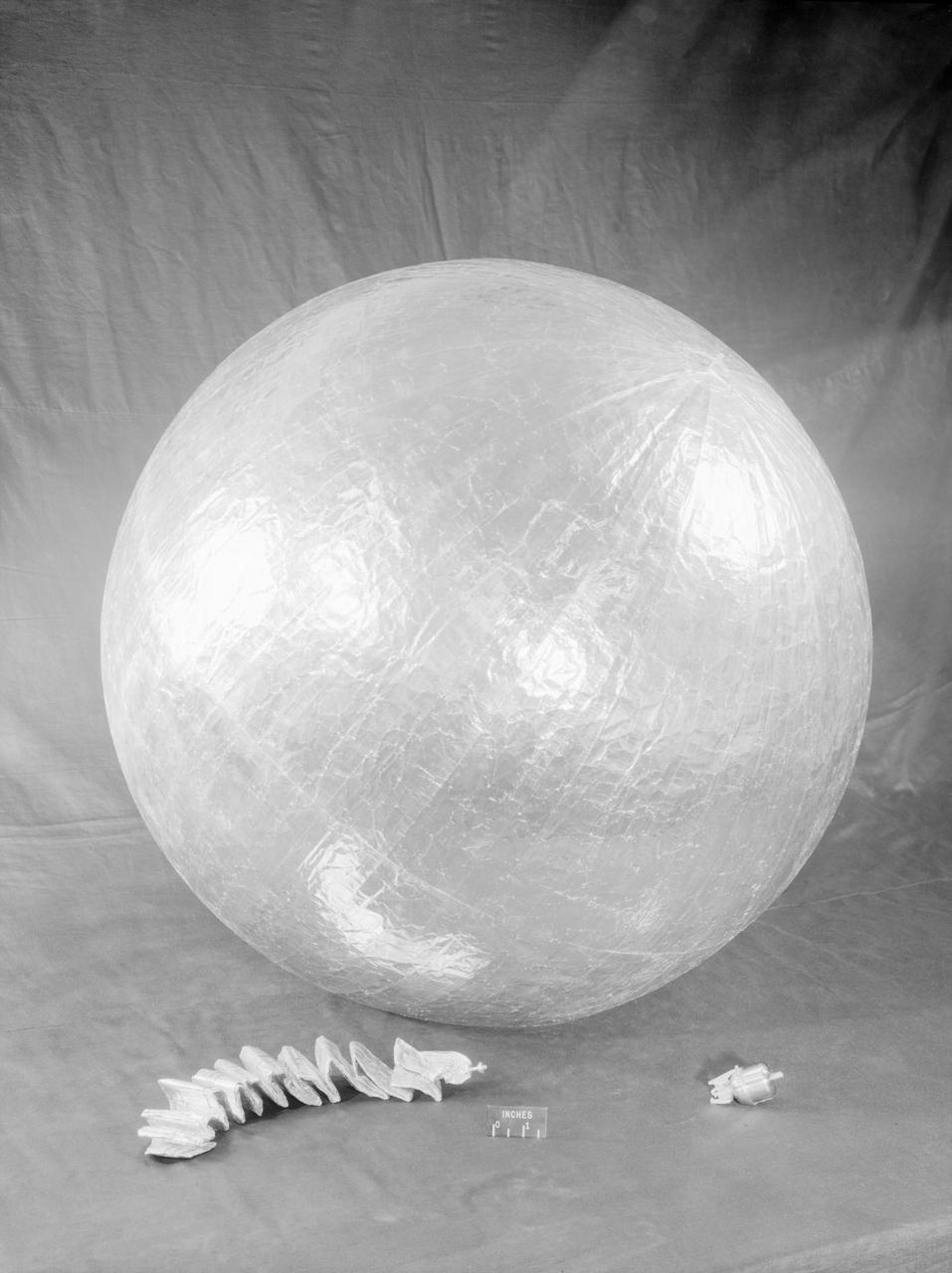
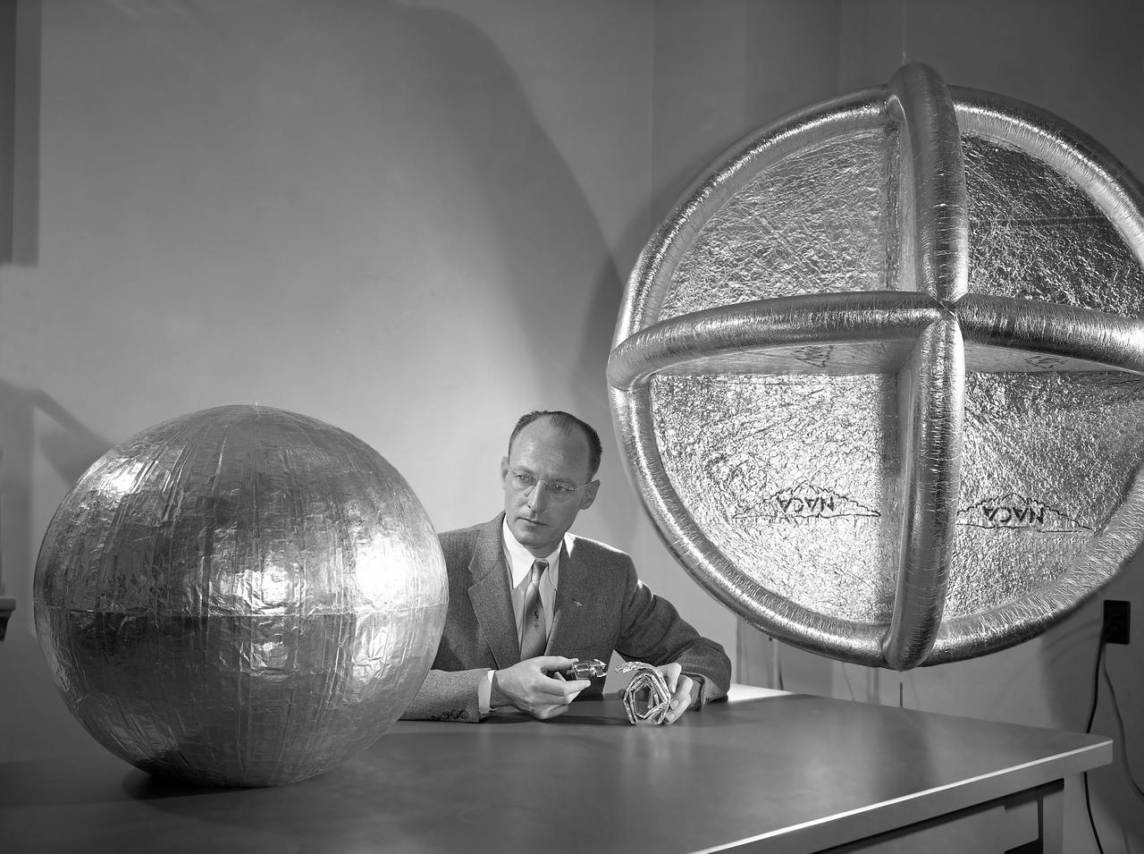
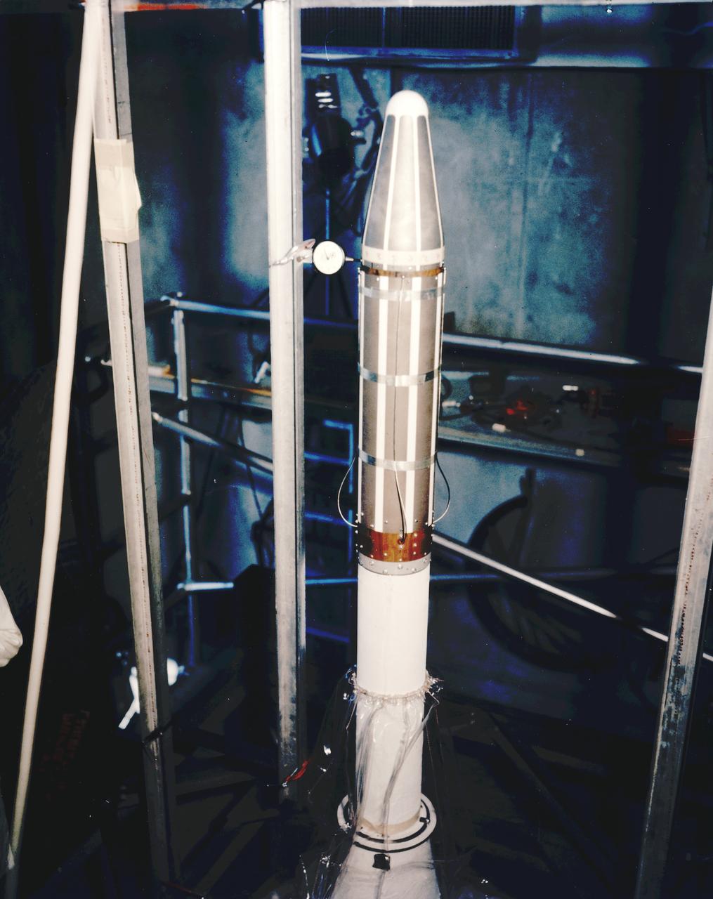
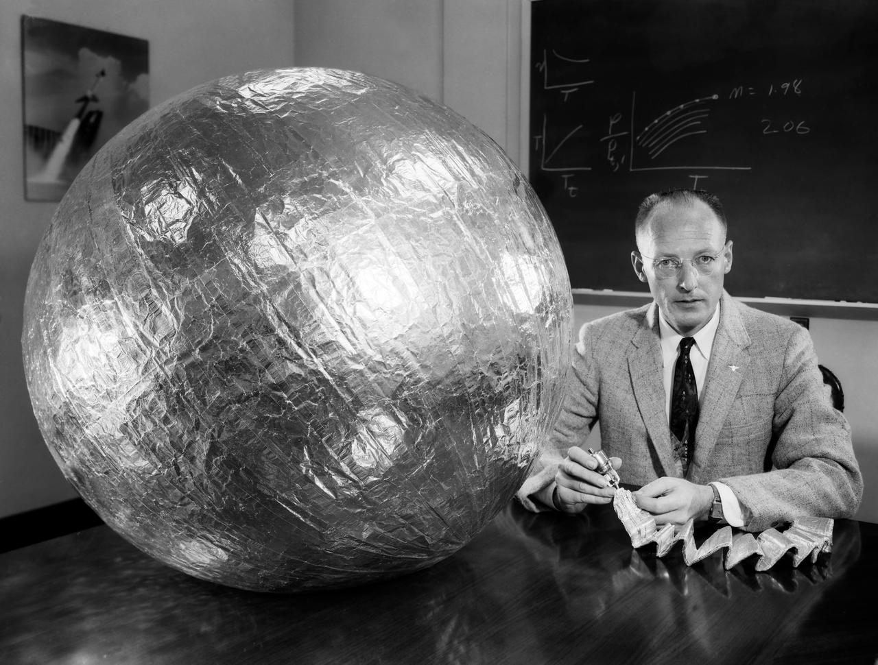
James Hansen describes the work on Project Echo s air density experiment known as the Sub-Satellite. Before launch engineers subjected the sub-satellite to many tests. Here, the sub-satellite is shown prior to tests to determine the capacity of the 30-inch Sub-Satellite to withstand the high temperature of direct sunlight in space, Langley researchers subjected it to 450 F heat test. Results indicated that the aluminum-covered Mylar plastic would effectively reflect the dangerous heat. -- Published in James R. Hansen, Spaceflight Revolution: NASA Langley Research Center From Sputnik to Apollo, NASA SP-4308, p. 168.
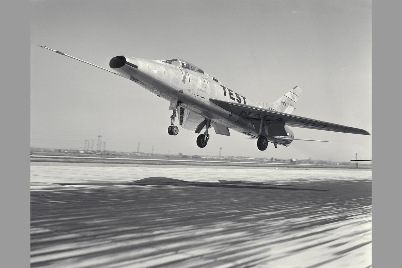
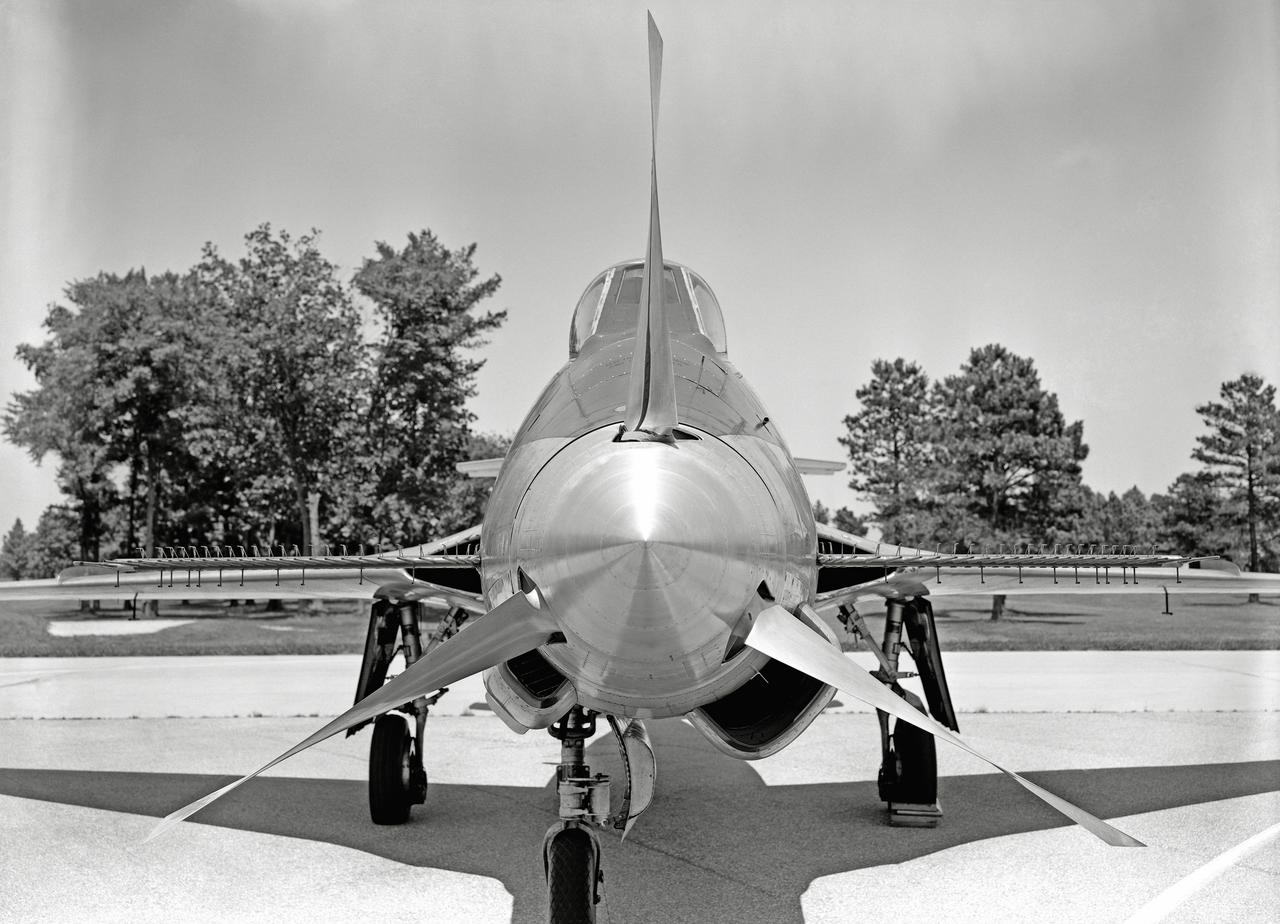
NACA Photographer North American F-100A (NACA-200) Super Sabre Airplane take-off. The blowing-tupe boundary-layer control on the leading- and trailing-edge provided large reductions in takeoff and landing approach speeds. Approach speeds were reduced by about 10 knots (Mar 1960). Note: Used in publication in Flight Research at Ames; 57 Years of Development and Validation of Aeronautical Technology NASA SP-1998-3300 fig. 102 and and Memoirs of a Flight Test Engneer NASA SP-2002-4525
Water Type Muffler Test
Phase SB Propeller installed on F88B
Water Type Muffler Test
L57-2809 Rocket model of McDonnell F4-H1 airplane on Terrier launcher with Nike booster, June 17, 1957. Photograph published in A New Dimension Wallops Island Flight Test Range: The First Fifteen Years by Joseph Shortal. A NASA publication. Page 500.
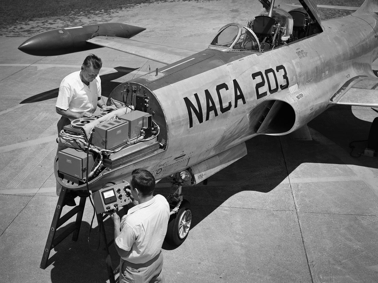
A Lockheed F-94B Starfire being equipped with an audio recording machine and sensors at the National Advisory Committee for Aeronautics (NACA) Lewis Flight Propulsion Laboratory. The NACA was investigating the acoustic effects caused by the engine’s nozzle and the air flowing along the fuselage. Airline manufacturers would soon be introducing jet engines on their passenger aircraft, and there was concern regarding the noise levels for both the passengers and public on the ground. NACA Lewis conducted a variety of noise reduction studies in its wind tunnels, laboratories, and on a F2H-2B Banshee aircraft. The F2H-2B Banshee’s initial test flights in 1955 and 1956 measured the noise emanating directly from airflow over the aircraft’s surfaces, particularly the wings. This problem was particularly pronounced at high subsonic speeds. The researchers found the majority of the noise occurred in the low and middle octaves. These investigations were enhanced with a series of flights using the F-94B Starfire. The missions measured wall-pressure, turbulence fluctuations, and mean velocity profiles. Mach 0.3 to 0.8 flights were flown at altitudes of 10,000, 20,000, and 30,000 feet with microphones mounted near the forward fuselage and on a wing. The results substantiated the wind tunnel findings. This photograph shows the tape recorder being installed in the F-94B’s nose.
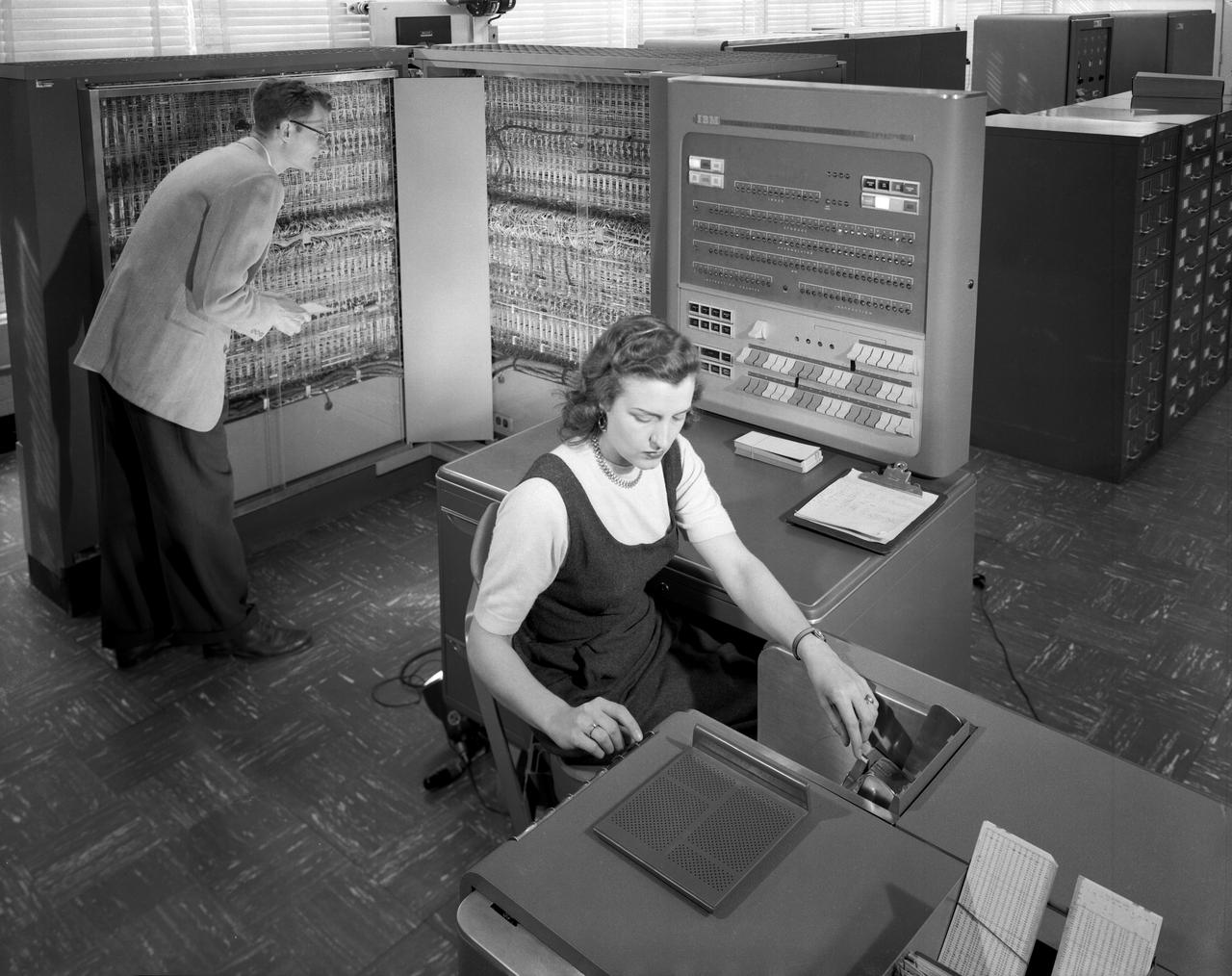
L57-989: Man and woman shown working with IBM type T04 electronic data processing machine.

Water Type Muffler Test
Overhead view of Bell XV-3 Convertiplane. First tilt rotor tested in the 40 x 80 wind tunnel. Transition aerodynamics studied; shown in hover mode.
Vertical model flying in Langley Research Center's Full Scale Tunnel.
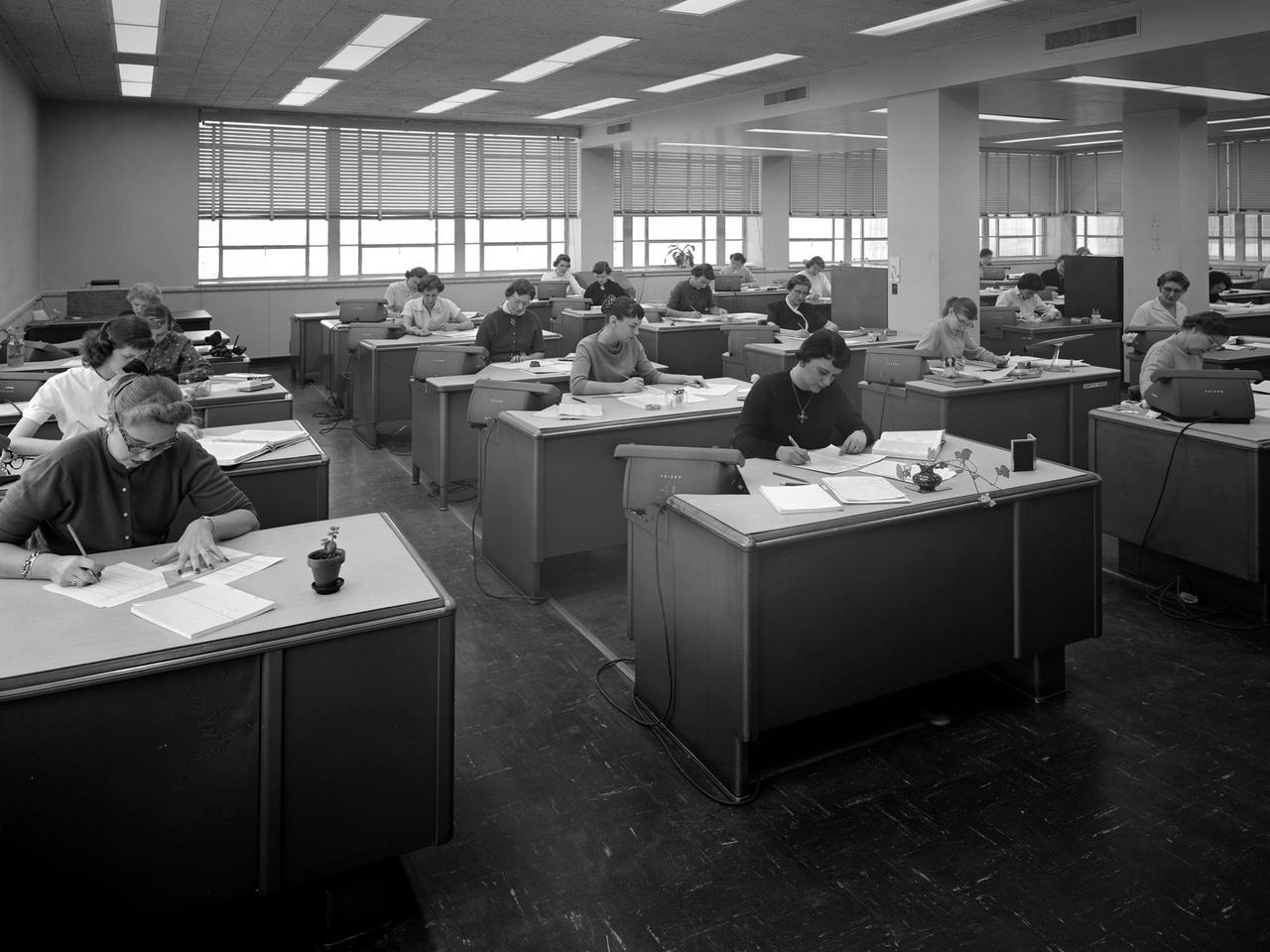
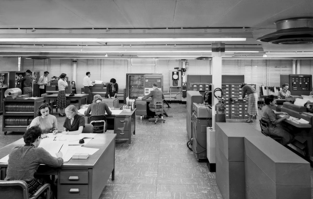
The staff of female computers at work in the 8- by 6-Foot Supersonic Wind Tunnel at the National Advisory Committee for Aeronautics (NACA) Lewis Flight Propulsion Laboratory. The lab’s Computer Section occupied three offices on the second story of the office building at the 8- by 6 facility. The largest office, seen in this photograph, contained approximately 35 women with advanced mathematical skills, a second office housed 20 to 25, and a third 10. Each major test facility at the laboratory had banks of mercury-filled manometer boards which measured pressure levels at various locations inside the facility’s test section. Often, one board consisting of 100 tubes produced a single data point. There could be scores of data points for each test run. Cameras were set up in front of the manometer boards to capture the readings throughout the test. The following day the computers, seen in this photograph, would receive the photographs and plot the data points on a graph. The process often took days. It might be weeks before the researchers received the results of their tests. The Friden adding machines can be seen on some of the desks.

Water Type Muffler Test
Engineer W.J. O Sullivan, Jr., seated beside 30 inch subsatellite. He holds inflation bottle and folded duplicate copy, July 1957.
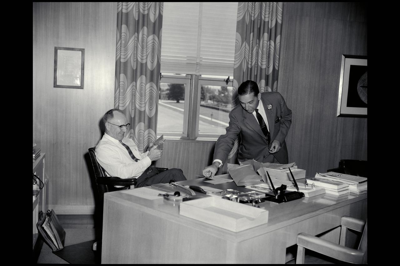
Smith J. DeFrance and J.F Parsons in Directors office
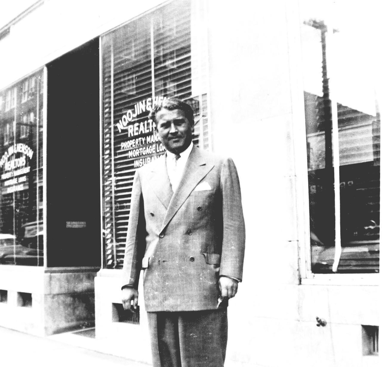
This snapshot, dated November 1957, shows Dr. von Braun in downtown Huntsville, Alabama.
NACA Photographer Portrait: Dr. Smith J. (Smithy) DeFrance, First Director of Ames Research Center 1940 - 1965 (then Ames Aeronautical Laboratory)
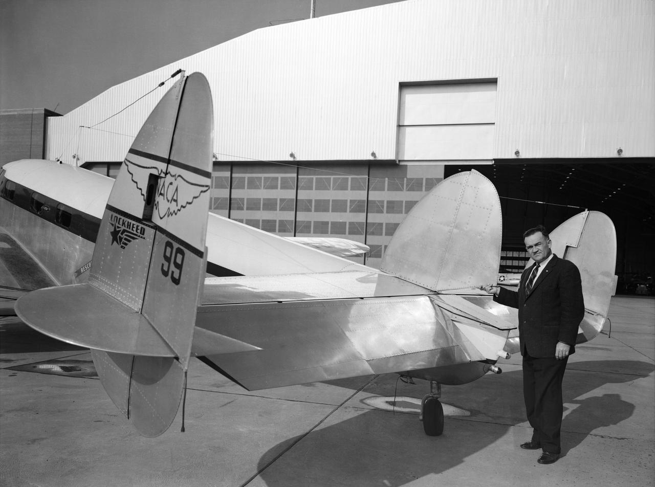
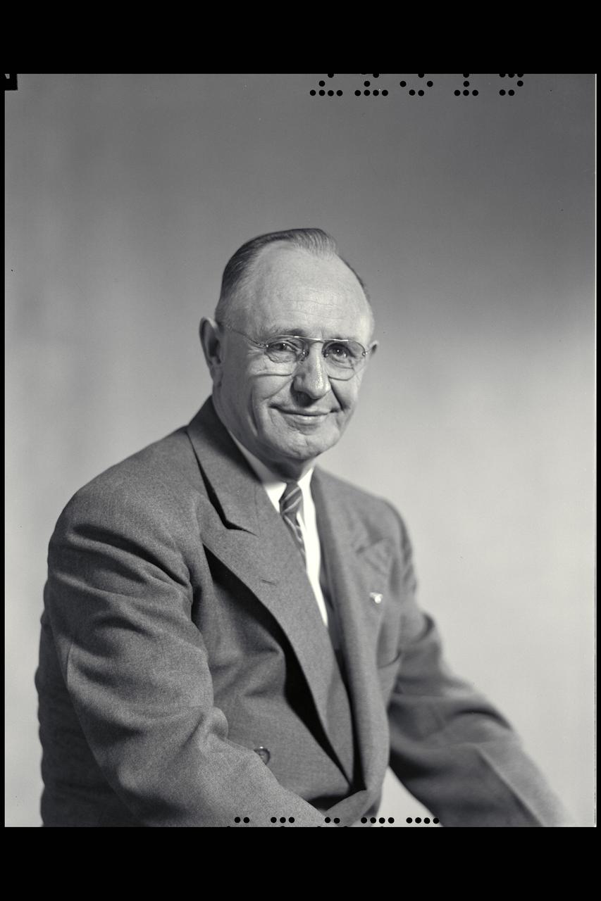
Melvin Gough at the Tail of a NACA Lockheed Plane
WS-110A "Brown Bomber"
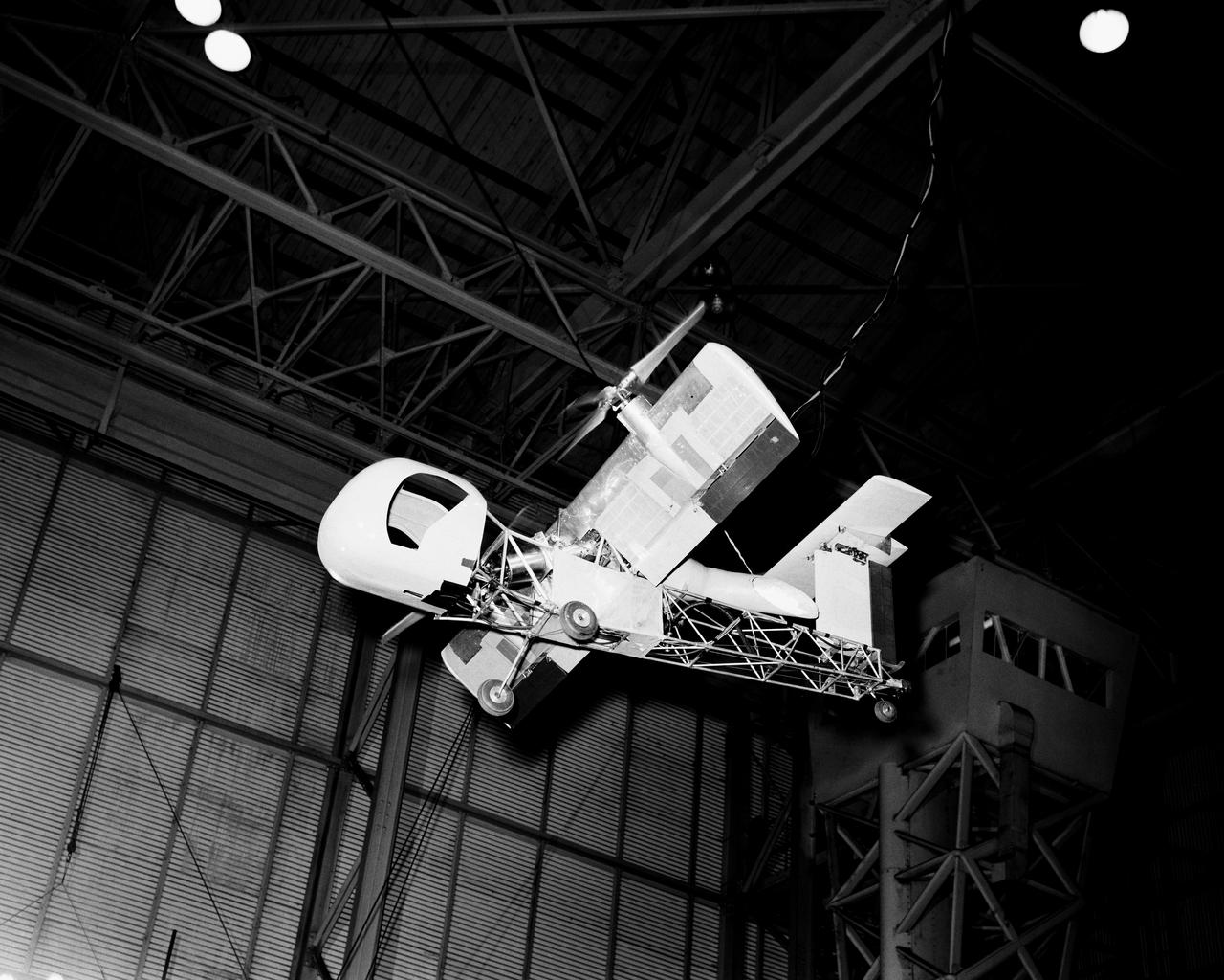
Vertical model flying in Langley Research Center's Full Scale Tunnel.
WS-110A "Brown Bomber"
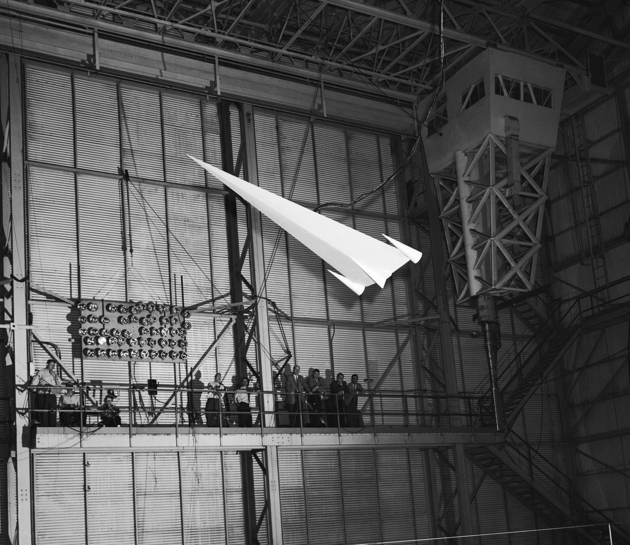
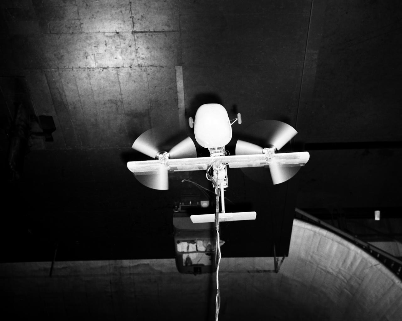
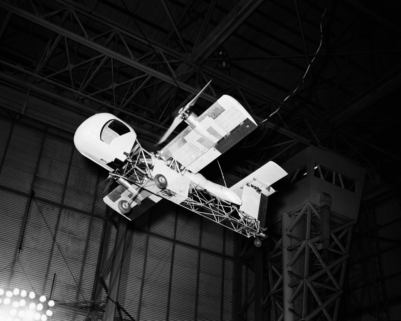
L57-1439 A model based on Langley s concept of a hypersonic glider was test flown on an umbilical cord inside the Full Scale Tunnel in 1957. Photograph published in Engineer in Charge: A History of the Langley Aeronautical Laboratory, 1917-1958 by James R. Hansen. Page 374.
Phase SB Propeller installed on F88B
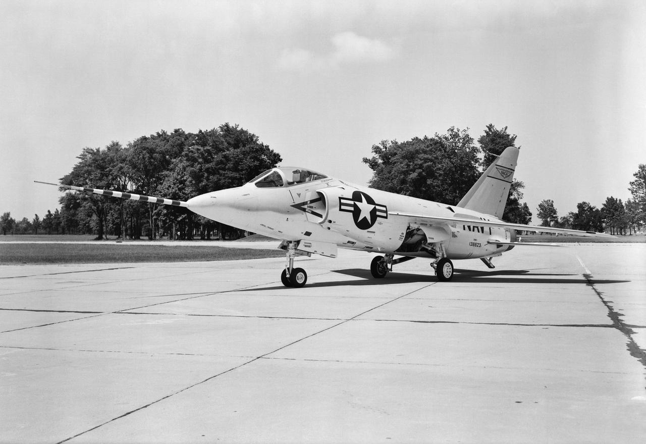
F11F Airplane
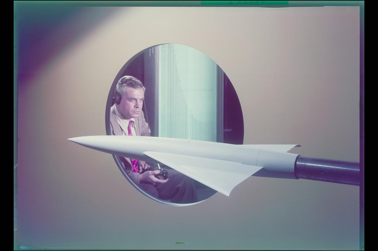
A researcher works a demonstration board in the Rocket Engine Test Facility during the 1957 Inspection of the National Advisory Committee for Aeronautics (NACA) Lewis Flight Propulsion Laboratory in Cleveland, Ohio. Representatives from the military, aeronautical industry, universities, and the press were invited to the laboratory to be briefed on the NACA’s latest research efforts and tour the test facilities. Over 1700 people visited the Lewis during the October 7-10, 1957 Inspection. The Soviet Union launched their first Sputnik satellite just days before on October 4. NACA Lewis had been involved in small rockets and propellants research since 1945, but the NACA leadership was wary of involving itself too deeply with the work since ballistics traditionally fell under the military’s purview. The Lewis research was performed by the High Temperature Combustion section in the Fuels and Lubricants Division in a series of small cinderblock test cells. The rocket group was expanded in 1952 and made several test runs in late 1954 using liquid hydrogen as a propellant. A larger test facility, the Rocket Engine Test Facility, was approved and became operational just in time for the Inspection.
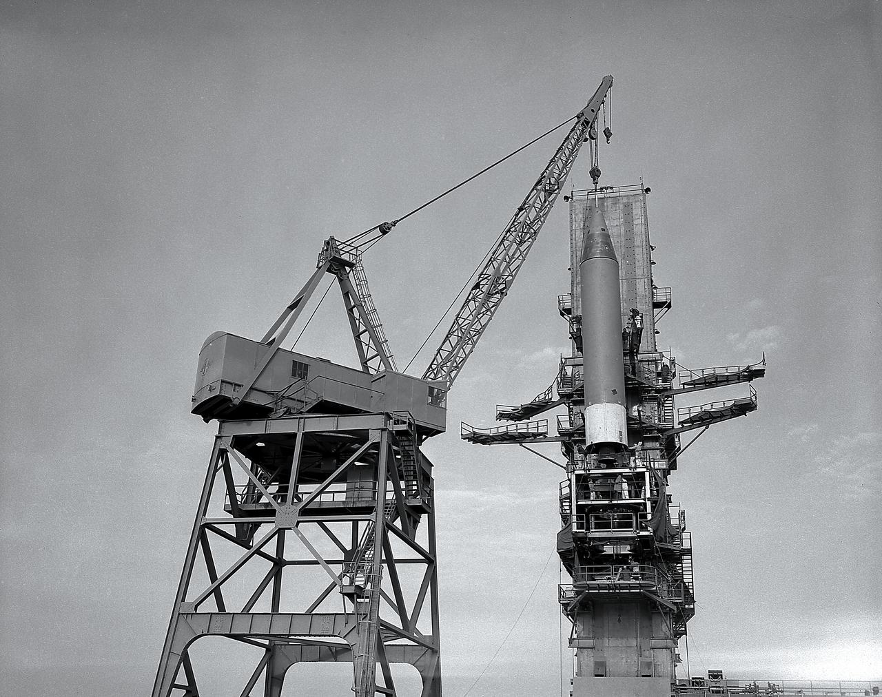
Installation of a Jupiter missile in ABMA (Army Ballistic Missile Agency) West Test Stand, Jan. 16, 1957. Jupiter was a 1500-mile range missile
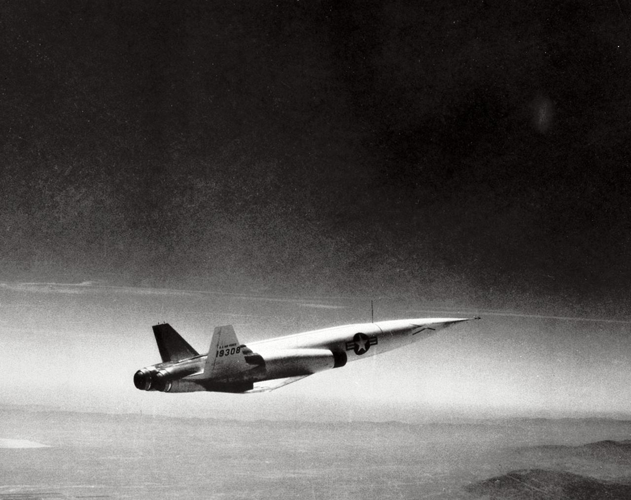
Navaho in flight, 1957. Navaho is a surface-to-surface missile developed by North American Aviation under the U.S. Air Force Navaho Program. The Navaho engine was an improvement of the V-2 engine. Though program began in March 1946 and was cancelled in July 1957, the research to develop the Navaho engine contributed to the development of the Redstone, Jupiter, Thor, and ATLAS engines.
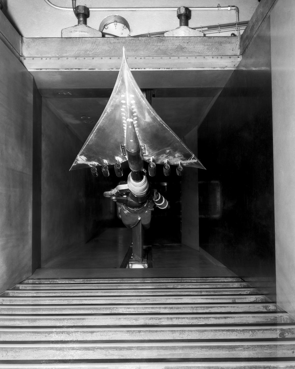
Charles Hall displaying tunnel model AR-2 which incorporates conical camber as the half-cone twist in the wings (in simulated 2x4' tunnel) Note: printed in 60 year at NASA Ames Research Center by Glenn Bugos NASA SP-2000-4314