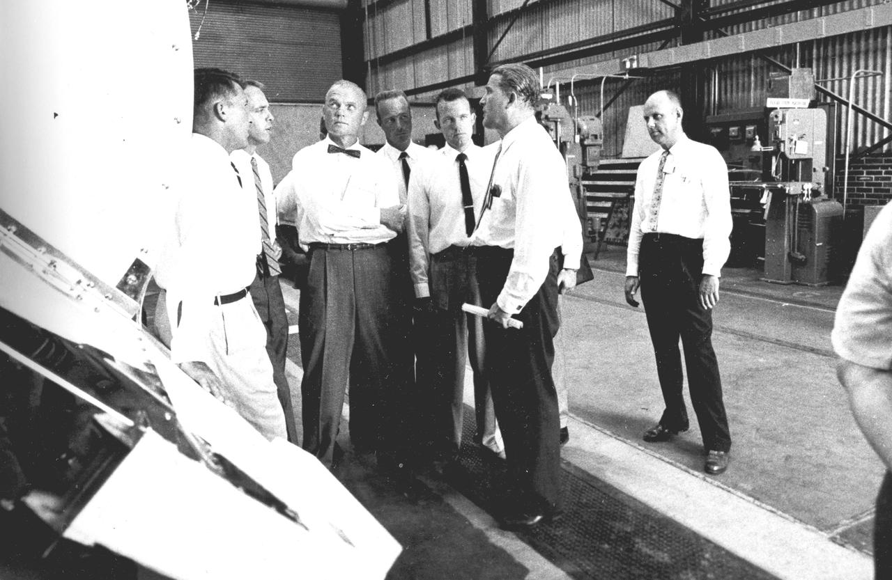
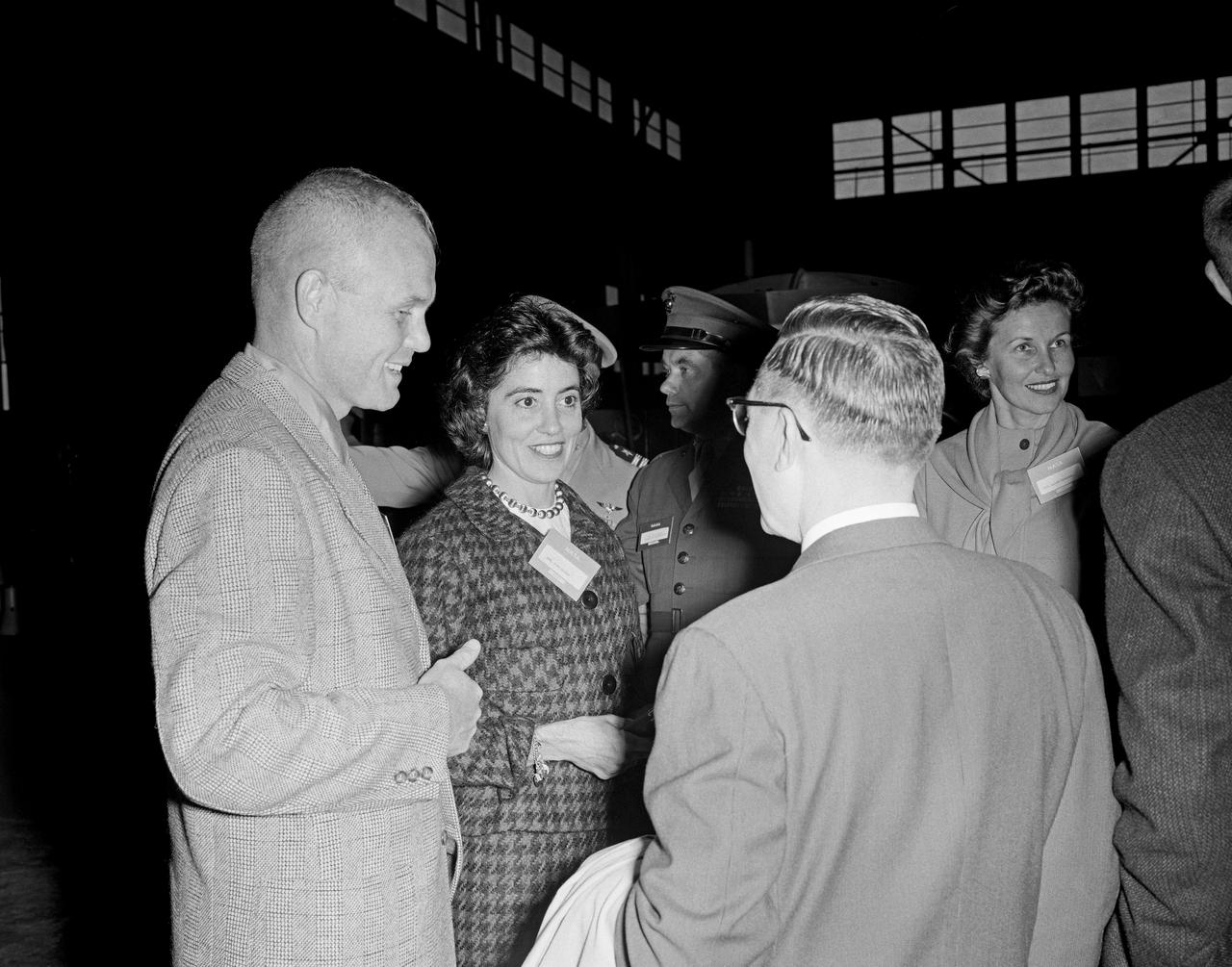
Five of the seven original astronauts are seen with Dr. von Braun inspecting the Mercury-Redstone hardware in the Fabrication Laboratory of Army Ballistic Missile Agency (ABMA) in 1959. Left to right: Astronauts Walter Schirra, Alan Shepard, John Glenn, Scott Carpenter, Gordon Cooper, and Dr. von Braun.
Boost glide model
On June 26, 1959, then-Langley-research Francis Rogallo examined the Rogallo wing in the 7x10 FT Tunnel. Originally conceived as a means of bringing manned spacecraft to controlled, soft landings, Rogallo's concept was avidly embraced by later generations of hang-gliding enthusiasts. -- Photograph published in Winds of Change, 75th Anniversary NASA publication (page 18), by James Schultz.

X-15 launch techniques were investigated using on-twentieth scale models mounted in the 7x10 FT Tunnel. -- Photograph published in Winds of Change, 75th Anniversary NASA publication (page 67), by James Schultz. -- Photograph also published in Sixty Years of Aeronautical Research 1917-1977 - a NASA publication (page 49), by David A. Anderton.
Vehicles and Missions Studies Charts, Space Capsule
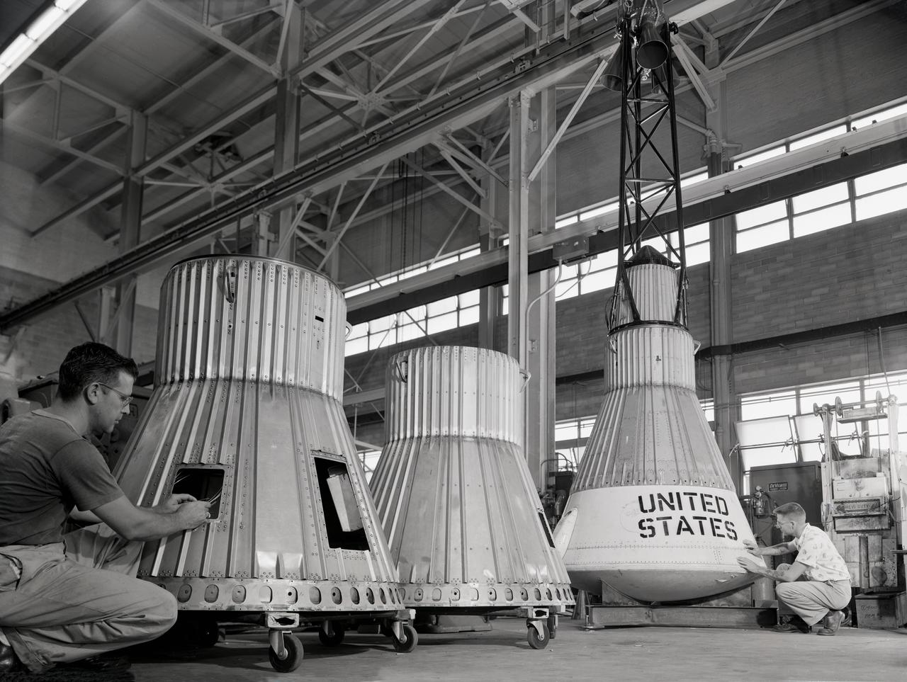
Assembling the Little Joe capsules. The capsules were manufactured in-house by Langley technicians. Three capsules are shown here in various stages of assembly. The escape tower and rocket motors shown on the completed capsule would be removed before shipping and finally assembly for launching at Wallops Island. Joseph Shortal wrote (vol. 3, p. 32): Design of the Little Joe capsules began at Langley before McDonnell started on the design of the Mercury capsule and was, therefore, a separate design. Although it was not designed to carry a man, it did have to carry a monkey. It had to meet the weight and center of gravity requirements of Mercury and withstand the same aerodynamic loads during the exit trajectory. Although in comparison with the overall Mercury Project, Little Joe was a simple undertaking, the fact that an attempt was made to condense a normal two-year project into a 6-month one with in house labor turned it into a major undertaking for Langley. Project Mercury: Little Joe: Boilerplate Mercury spacecraft undergo fabrication at the shops of the Langley Research Center. They will launched atop Little Joe rockets to test the spacecraft recovery systems. -- Published in Joseph A. Shortal, History of Wallops Station: Origins and Activities Through 1949, (Wallops Island, VA: National Aeronautics and Space Administration, Wallops Station, nd), Comment Edition. L59-4947 Technicians prepare a Little Joe launch vehicle prototype for the Mercury space program, 1959. Photograph published in Winds of Change, 75th Anniversary NASA publication, page 76, by James Schultz
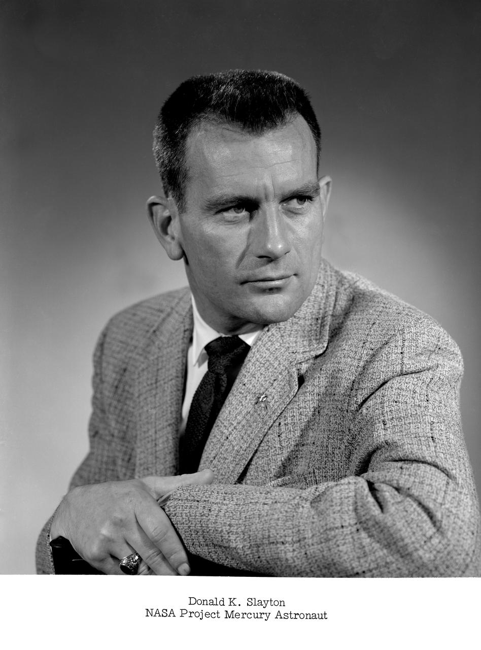
NASA Project Mercury astronaut -- Slayton was later known as Deke.
Water drop and recovery from shore-based crane at Langley's back river.
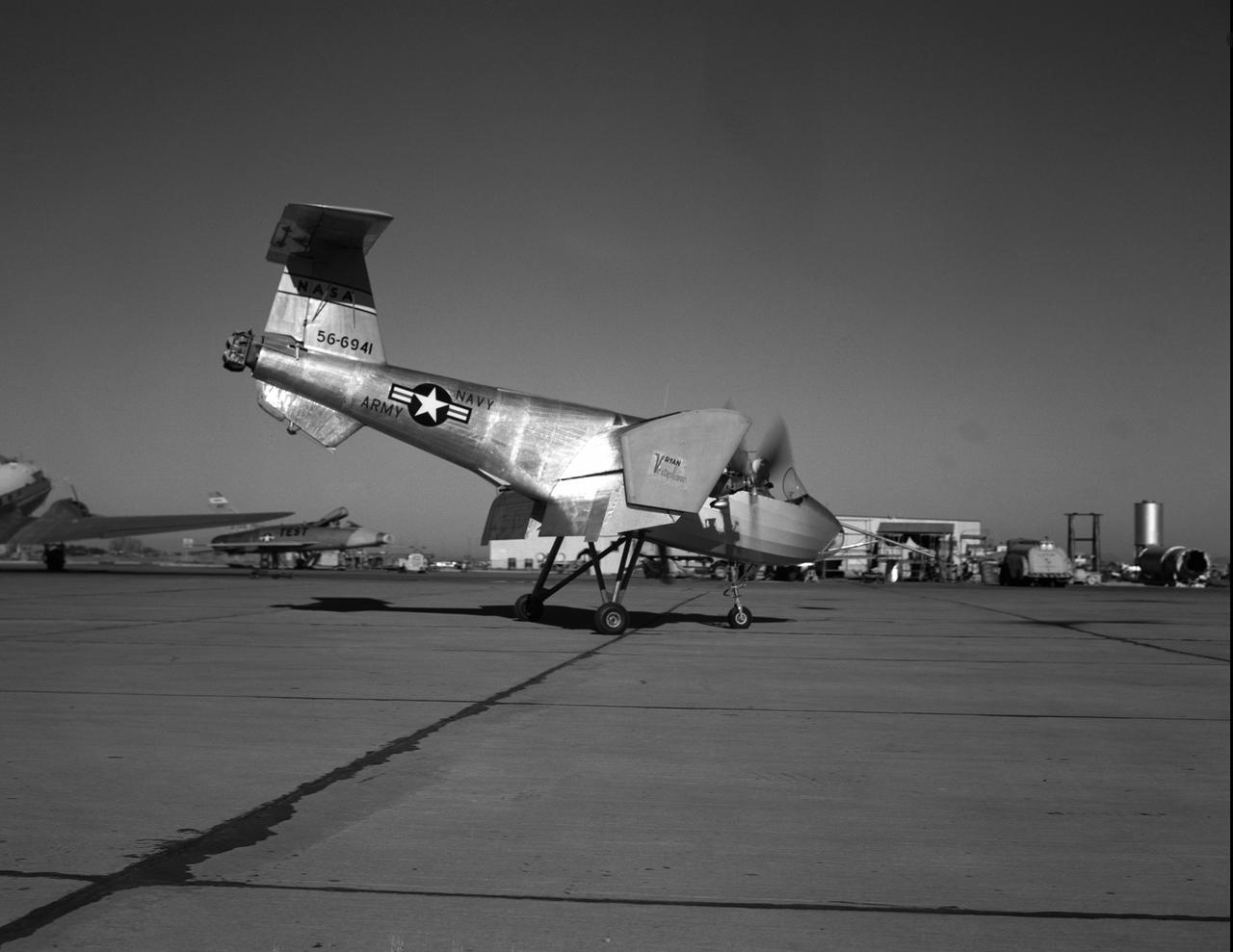
NACA Photographer Ryan model Number 92 Vertiplane
Project Mercury: M-1 model in the 11ft w.t. with engineer
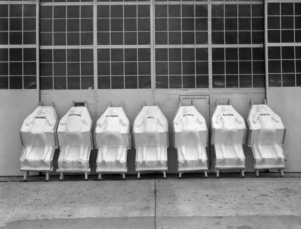
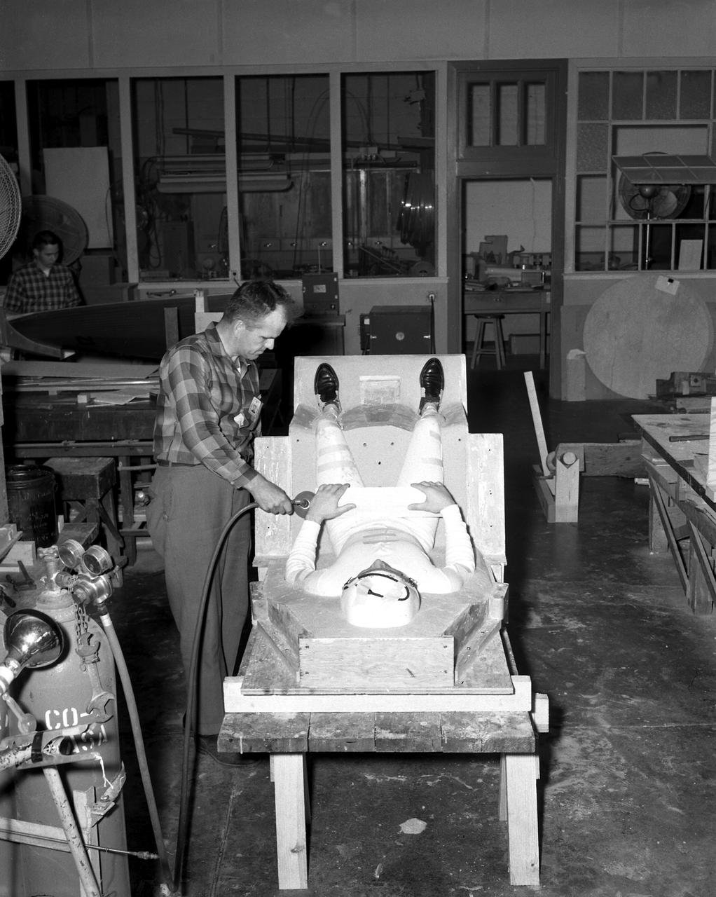
Molds for couches for test pilots, line the NASA Langley Research Centers model shop wall. The names of the test subjects (Langley employees) are written on the back. The couches are similar to those made for each astronaut and fitted into the Mercury capsules for manned spaceflight.
Air Bearings and Stable Platform

L59-3802 Nike-Cajun sounding rocket with University of Iowa payload on launcher at Wallops for flight test, May 20, 1959. Photograph published in A New Dimension Wallops Island Flight Test Range: The First Fifteen Years by Joseph Shortal. A NASA publication. Page 698.

L59-7932 First University of Michigan Strongarm sounding rocket on launcher at Wallops for test, November 10, 1959. Photograph published in A New Dimension Wallops Island Flight Test Range: The First Fifteen Years by Joseph Shortal. A NASA publication. Page 701.E5-188 Shop and Launcher Pictures
Women Scientists: Lucille Coltrane, Jean Clark Keating, Katherine Cullie Speegle, Doris "Dot" Lee, Ruth Whitman, and Emily Stephens Mueller,Lucille Coltrane is at the far left. She was a computer and worked for Norm Crabill who provided positive identification. Lucille authored a NACA Research Memorandum, Investigation of Two Bluff Shapes in Axial Free Flight Over a Mach Number Range From 0.35 to 2.15 in 1958. Next to Lucille is Jean Clark Keating. Jean was identified by Mary Woerner who said that both Jean and her husband Jerry are now deceased. The third woman from the left is Katherine Cullie Speegle. Katherine co-authored two research papers: Preliminary Results From a Free-Flight Investigation of Boundary-Layer Transition and Heat Transfer on a Highly Polished 8-Inch-Diameter Hemisphere-Cylinder at Mach Numbers up to 3 and Reynolds Numbers Based on a Length of 1 Foot up to 17.7 x 10 to the 6th and Heat Transfer For Mach Numbers Up to 2.2 and Pressure Distributions for Mach Numbers Up to 4.7 From Flight Investigations of a Flat-Face Cone and a Hemisphere-Cone. Norm remembered the woman standing as Doris. Mary Alice identified her as Doris 'Dot' Lee, who worked with Katherine Speegle. Dot was married to a NASA engineer named John Lee. Next to Doris is Ruth Whitman. Norm remembered she and her husband owned a Howard DGA 15 at the airport in WEst Point. That prompted Mary Alice to remember her name and that her husband was Jim. The woman seated on the right is Emily Stephens Mueller. Norm remembers that Emily went to Houston as part of the Space Task Group, but retired back here on the peninsula. In 2008, Emily attended the NACA Reunion X11. She walked over to a table of books about the history of NACA, former NACA facilities and the organization's aviation pioneers and saw a book about women of flight from the Dryden Research Center and paused, then pointed somewhat in amazement. "ThatÕs me," she said of a picture on the cover of her on the far left of a line of women. She was at Dryden from 1948-49.
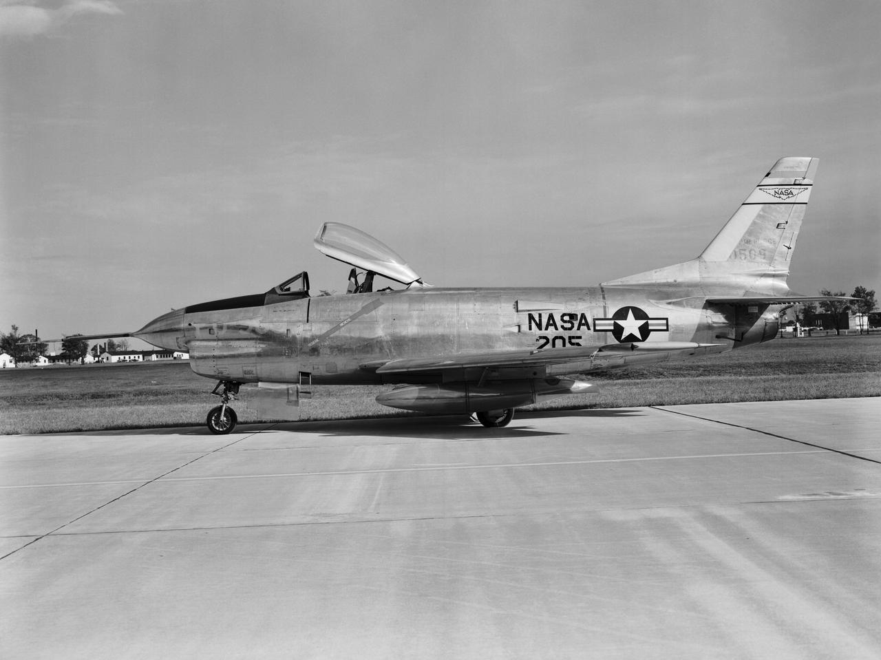
F-86 D NASA 205
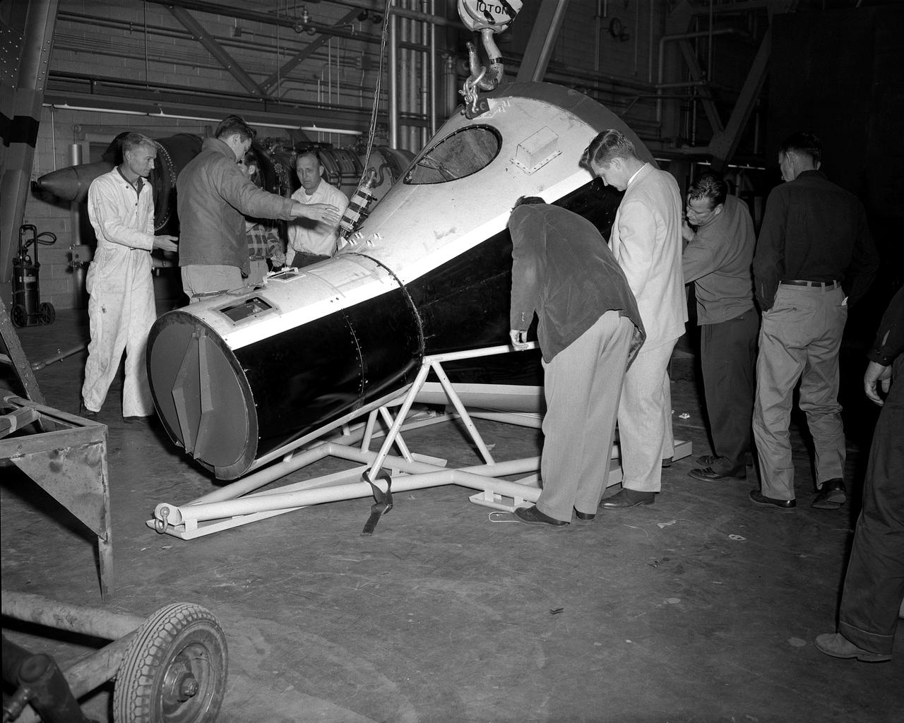
Mock-up of the Mercury capsule on display at the first NASA inspection held on October 24, 1959.
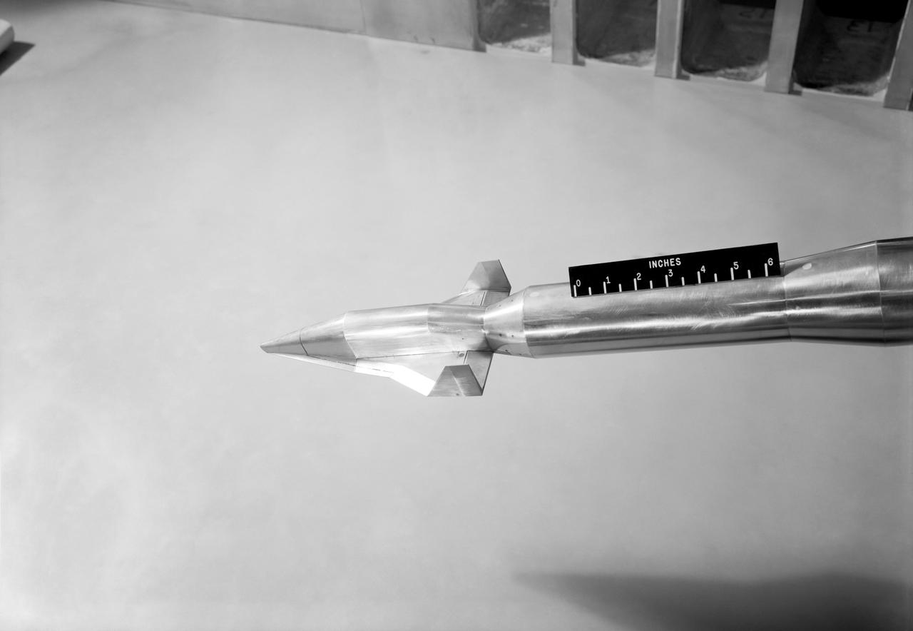
HSC Model 154 Dyna Soar (Martin-Bell)
Martin-Bell Dyna Soar I in Unitary Tunnel
Publicity photograph of a technician measuring a wind tunnel model of the Little Joe test vehicle. Joseph Shortal noted that (vol. 3, p. 29): The largest project at Wallops in support of Mercury was the Little Joe project, designed to qualify the abort-escape system under flight conditions. James Hansen (p. 47) writes: STG engineers Max Faget and Paul Purser, then of Langley's PARD, had conceived Little Joe as a space capsule test vehicle even before the establishment of NASA and the formation of the STG. Girlruth understood the importance of the Little Joe tests: We had to be sure there were no serious performance and operational problems that we had simply not thought of in such a new and radical type of flight vehicle. -- Published in James R. Hansen, Spaceflight Revolution: NASA Langley Research Center From Sputnik to Apollo, (Washington: NASA, 1995), p. 47 Joseph A. Shortal, History of Wallops Station: Origins and Activities Through 1949, (Wallops Island, VA: National Aeronautics and Space Administration, Wallops Station, nd), Comment Edition.

Air Force Javelin Rocket on Launcher (USAF JV-1) Wallops Model D4-78 L59-5144 First AFSWC Javelin sounding rocket ready for flight test, July 7, 1959. Photograph published in A New Dimension Wallops Island Flight Test Range: The First Fifteen Years by Joseph Shortal. A NASA publication. Page 704.
Miscellaneous Charts, space capsule
Flat Delta Model Flying in Full Scale Tunnel (FST) (Boiseau)
In this photo, (left to right) Army Ballistic Missile Agency (ABMA) Missile Firing Laboratory Chief Dr. Kurt Debus, Director of the ABMA Development Operations Division, Dr. von Braun and an unidentified individual in blockhouse during the CM-21 (Jupiter) firing. The Jupiter missile CM-21 became the first Chrysler production qualification missile to be fired and in March 1959 launched the Pioneer IV.
Vehicles and Missions Studies Charts, Space Capsule
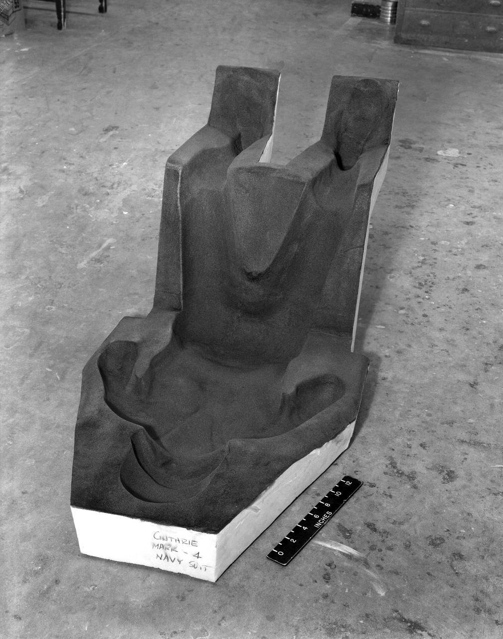
Lockfoam Couch
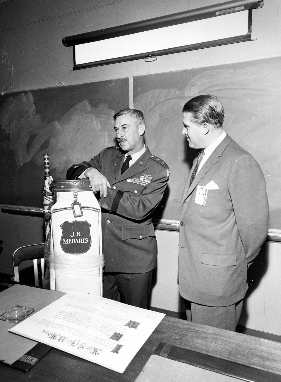
Marshall Space Flight Center Director Wernher von Braun presents General J.B. Medaris with a new golf bag. General Medaris, (left) was a Commander of the Army Ballistic Missile Agency (ABMA) in Redstone Arsenal, Alabama during 1955 to 1958.
In July 1959, William J. O Sullivan (right standing) and unidentified engineer examine the capsule containing the tightly folded and packed 12 diameter Beacon satellite inside. Taken from NASA SP-4308 Pg. 174
Juno II (AM-19B), the booster for Payload (Beacon), August 6 1959.
The Vangard III satellite to study the magnetic field and radiation belt in orbit. NASA successfully launched Vanguard III (SLV-7) from Cape Canaveral, Florida on September 18, 1959.
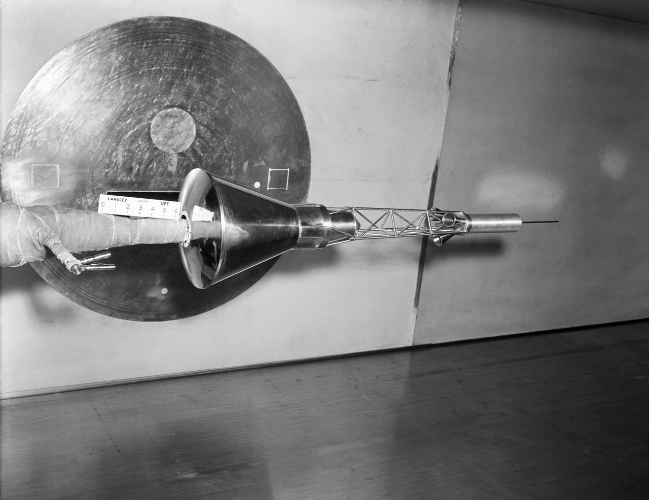
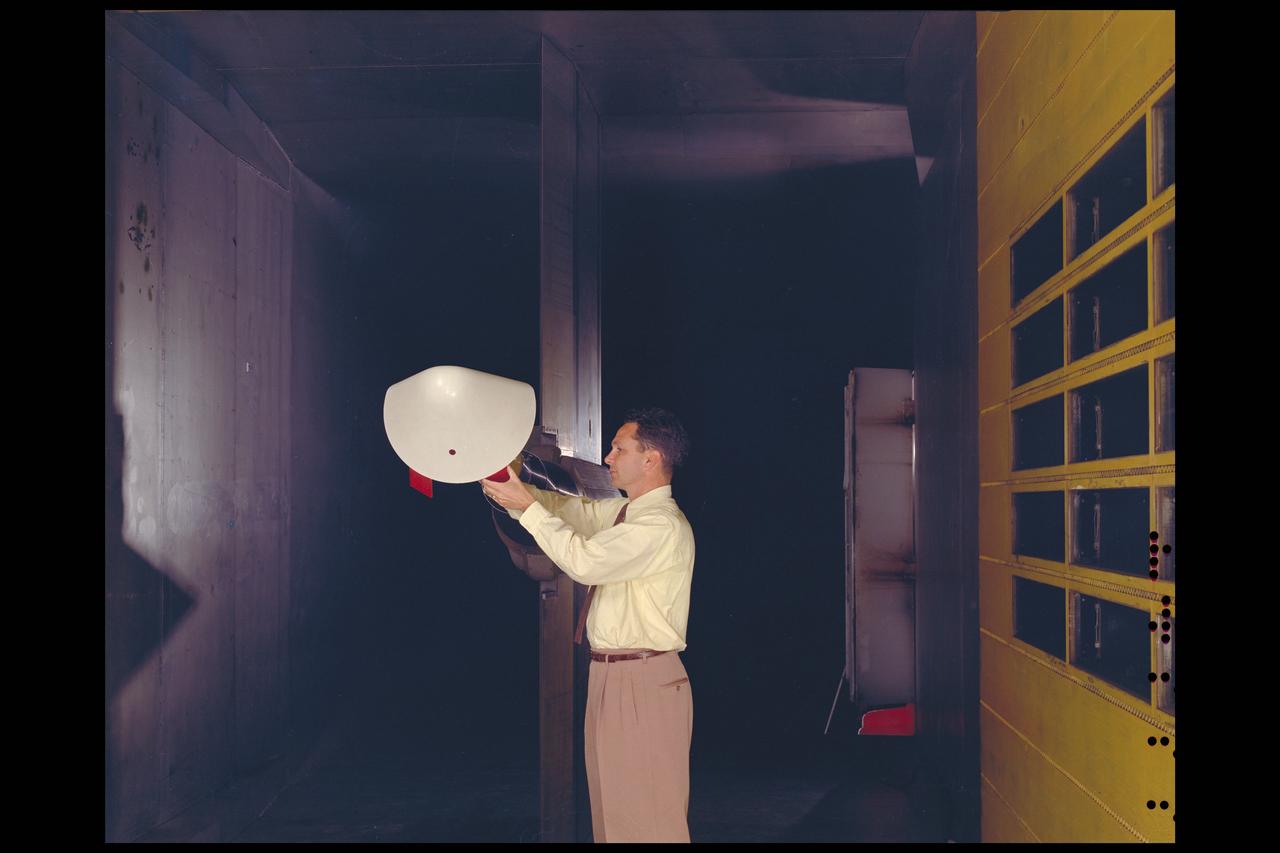
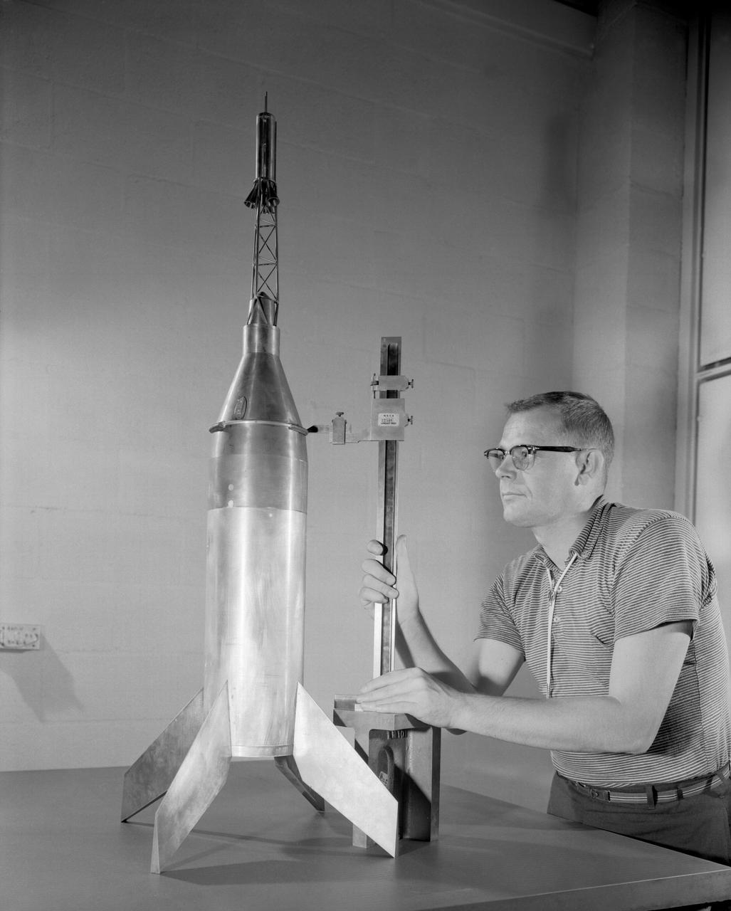
A one-sixth scale model of the Mercury capsule being tested in the 300-mph 7 x 10-foot wind tunnel.
Investigation of a tilt-wing/propeller model with blowing flaps. 3/4 front view, tilt wing model, wing position = 0deg. C-123 fuselage, conventional struts, 4 props
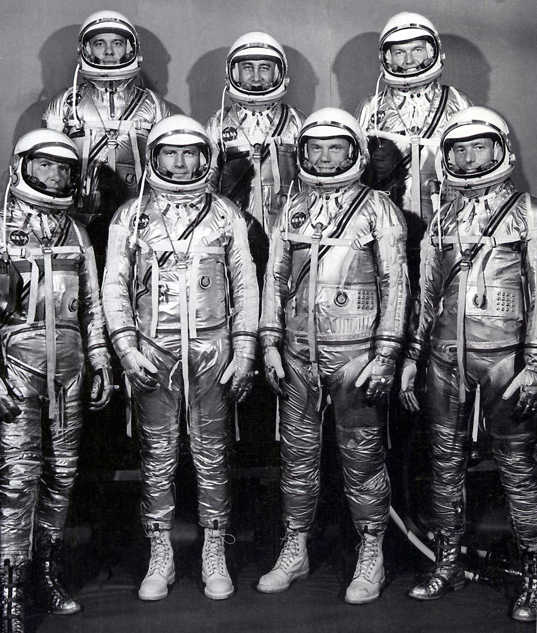
The group portrait of the original seven astronauts for the Mercury Project. NASA selected its first seven astronauts on April 27, 1959. Left to right at front: Walter M. Wally Schirra, Donald K. Deke Slayton, John H. Glenn, Jr., and Scott Carpenter. Left to right at rear: Alan B. Shepard, Virgil I. Gus Grissom, and L. Gordon Cooper, Jr.
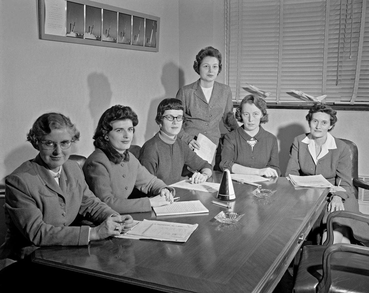
Women Scientists: Lucille Coltrane, Jean Clark Keating, Katherine Cullie Speegle, Doris 'Dot' Lee, Ruth Whitman, and Emily Stephens Mueller,Lucille Coltrane is at the far left. She was a computer and worked for Norm Crabill who provided positive identification. Lucille authored a NACA Research Memorandum, Investigation of Two Bluff Shapes in Axial Free Flight Over a Mach Number Range From 0.35 to 2.15 in 1958. Next to Lucille is Jean Clark Keating. Jean was identified by Mary Woerner who said that both Jean and her husband Jerry are now deceased. The third woman from the left is Katherine Cullie Speegle. Katherine co-authored two research papers: Preliminary Results From a Free-Flight Investigation of Boundary-Layer Transition and Heat Transfer on a Highly Polished 8-Inch-Diameter Hemisphere-Cylinder at Mach Numbers up to 3 and Reynolds Numbers Based on a Length of 1 Foot up to 17.7 x 10 to the 6th and Heat Transfer For Mach Numbers Up to 2.2 and Pressure Distributions for Mach Numbers Up to 4.7 From Flight Investigations of a Flat-Face Cone and a Hemisphere-Cone. Norm remembered the woman standing as Doris. Mary Alice identified her as Doris 'Dot' Lee, who worked with Katherine Speegle. Dot was married to a NASA engineer named John Lee. Next to Doris is Ruth Whitman. Norm remembered she and her husband owned a Howard DGA 15 at the airport in WEst Point. That prompted Mary Alice to remember her name and that her husband was Jim. The woman seated on the right is Emily Stephens Mueller. Norm remembers that Emily went to Houston as part of the Space Task Group, but retired back here on the peninsula. In 2008, Emily attended the NACA Reunion X11. She walked over to a table of books about the history of NACA, former NACA facilities and the organization's aviation pioneers and saw a book about women of flight from the Dryden Research Center and paused, then pointed somewhat in amazement. "That’s me," she said of a picture on the cover of her on the far left of a li
Vehicles and Missions Studies Charts, Space Capsule
This photograph shows Dr. von Braun, second from the left, in the blockhouse at the Florida launch facilities on March 3, 1959. He and others gathered for the launch of the Pioneer IV satellite. On the left of Dr. von Braun is Kurt Debus, who managed the Florida launch facilities. To the right of Dr. von Braun is Army General John B. Medaris. Next to him is General John Barclay. At this time, Dr. von Braun and his associates were members of the Army Ballistic Missile Agency in Huntsville, Alabama.

Assembling the Little Joe capsules. The capsules were manufactured in-house by Langley technicians. Three capsules are shown here in various stages of assembly. The escape tower and rocket motors shown on the completed capsule would be removed before shipping and finally assembly for launching at Wallops Island. Joseph Shortal wrote (vol. 3, p. 32): Design of the Little Joe capsules began at Langley before McDonnell started on the design of the Mercury capsule and was, therefore, a separate design. Although it was not designed to carry a man, it did have to carry a monkey. It had to meet the weight and center of gravity requirements of Mercury and withstand the same aerodynamic loads during the exit trajectory. Although in comparison with the overall Mercury Project, Little Joe was a simple undertaking, the fact that an attempt was made to condense a normal two-year project into a 6-month one with in house labor turned it into a major undertaking for Langley. Project Mercury: Little Joe: Boilerplate Mercury spacecraft undergo fabrication at the shops of the Langley Research Center. They will launched atop Little Joe rockets to test the spacecraft recovery systems. -- Published in Joseph A. Shortal, History of Wallops Station: Origins and Activities Through 1949, (Wallops Island, VA: National Aeronautics and Space Administration, Wallops Station, nd), Comment Edition. L59-4947 Technicians prepare a Little Joe launch vehicle prototype for the Mercury space program, 1959. Photograph published in Winds of Change, 75th Anniversary NASA publication, page 76, by James Schultz
Assembling the Little Joe capsules. The capsules were manufactured in-house by Langley technicians. Three capsules are shown here in various stages of assembly. The escape tower and rocket motors shown on the completed capsule would be removed before shipping and finally assembly for launching at Wallops Island. Joseph Shortal wrote (vol. 3, p. 32): Design of the Little Joe capsules began at Langley before McDonnell started on the design of the Mercury capsule and was, therefore, a separate design. Although it was not designed to carry a man, it did have to carry a monkey. It had to meet the weight and center of gravity requirements of Mercury and withstand the same aerodynamic loads during the exit trajectory. Although in comparison with the overall Mercury Project, Little Joe was a simple undertaking, the fact that an attempt was made to condense a normal two-year project into a 6-month one with in house labor turned it into a major undertaking for Langley. Project Mercury: Little Joe: Boilerplate Mercury spacecraft undergo fabrication at the shops of the Langley Research Center. They will launched atop Little Joe rockets to test the spacecraft recovery systems. -- Published in Joseph A. Shortal, History of Wallops Station: Origins and Activities Through 1949, (Wallops Island, VA: National Aeronautics and Space Administration, Wallops Station, nd), Comment Edition. L59-4947 Technicians prepare a Little Joe launch vehicle prototype for the Mercury space program, 1959. Photograph published in Winds of Change, 75th Anniversary NASA publication, page 76, by James Schultz
Astronauts at 1959 Langley Inspection
Juno II (AM-14) on the launch pad just prior to launch, March 3, 1959. The payload of AM-14 was Pioneer IV, America's first successful lunar mission. The Juno II was a modification of Jupiter ballistic missile
Martin-Bell Dyna Soar I in Unitary Tunnel
Space Flight Charts, Space Capsule
Vehicles and Missions Studies Charts, Space Capsule
Martin-Bell Dyna Soar Model B.W.V
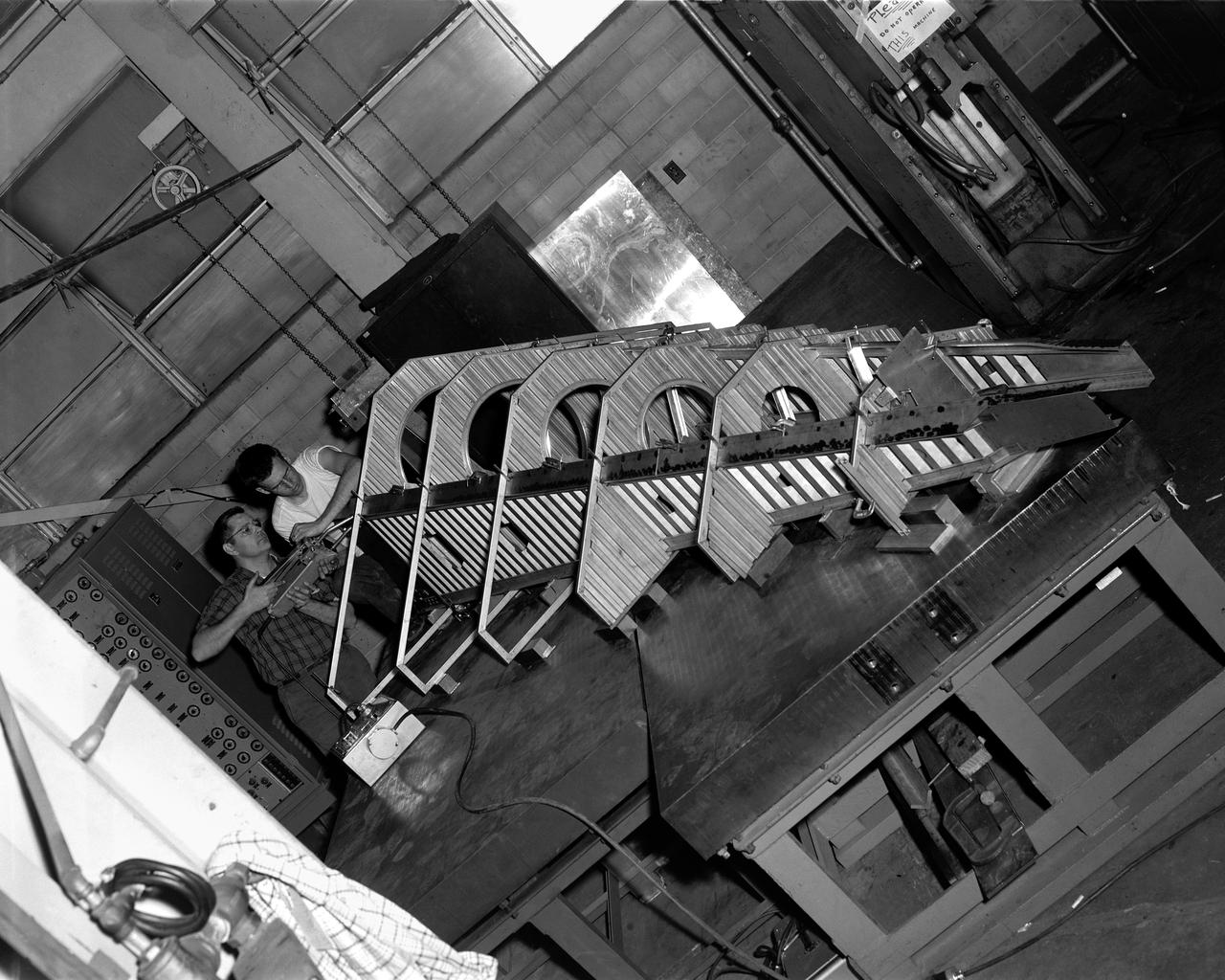
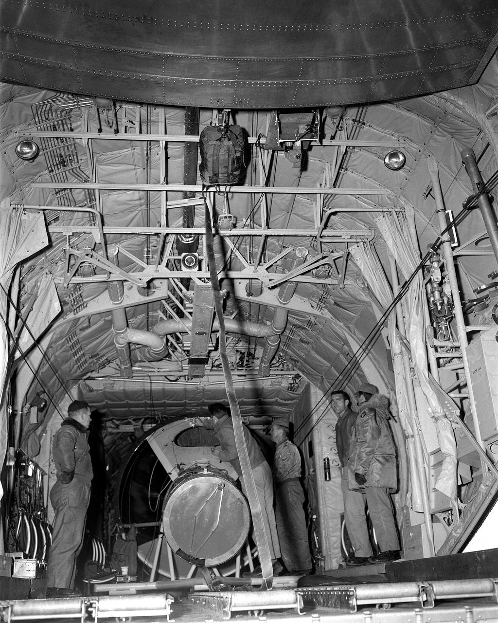
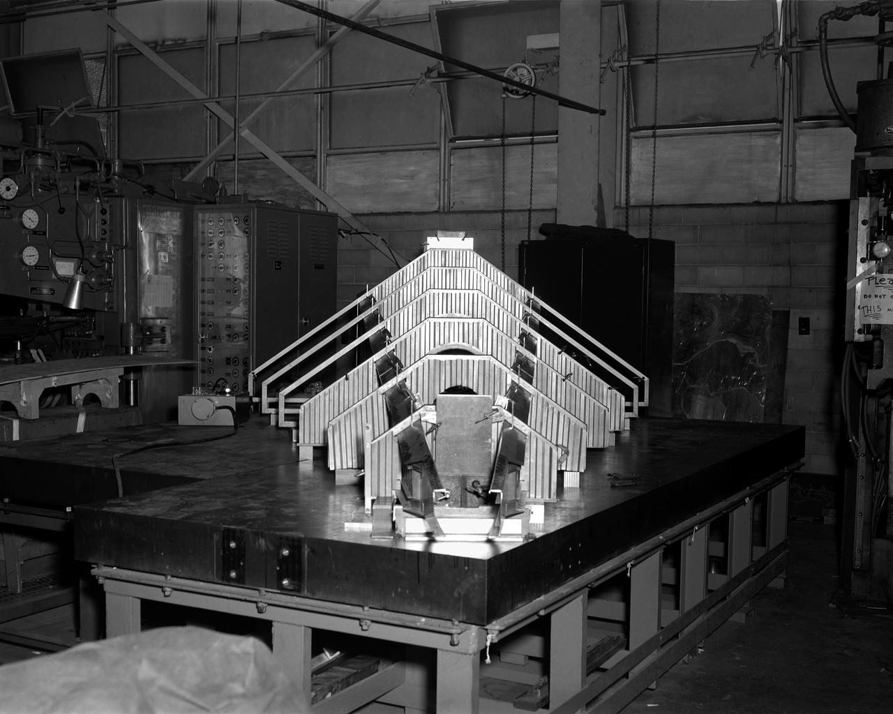
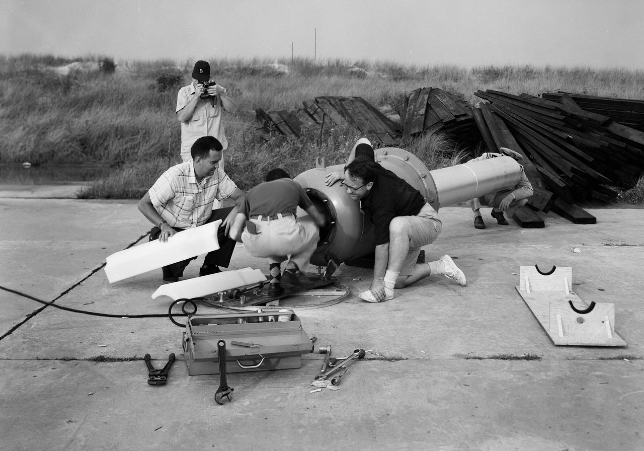
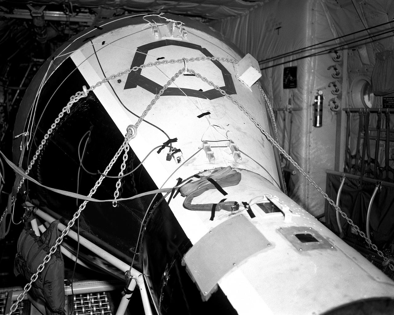
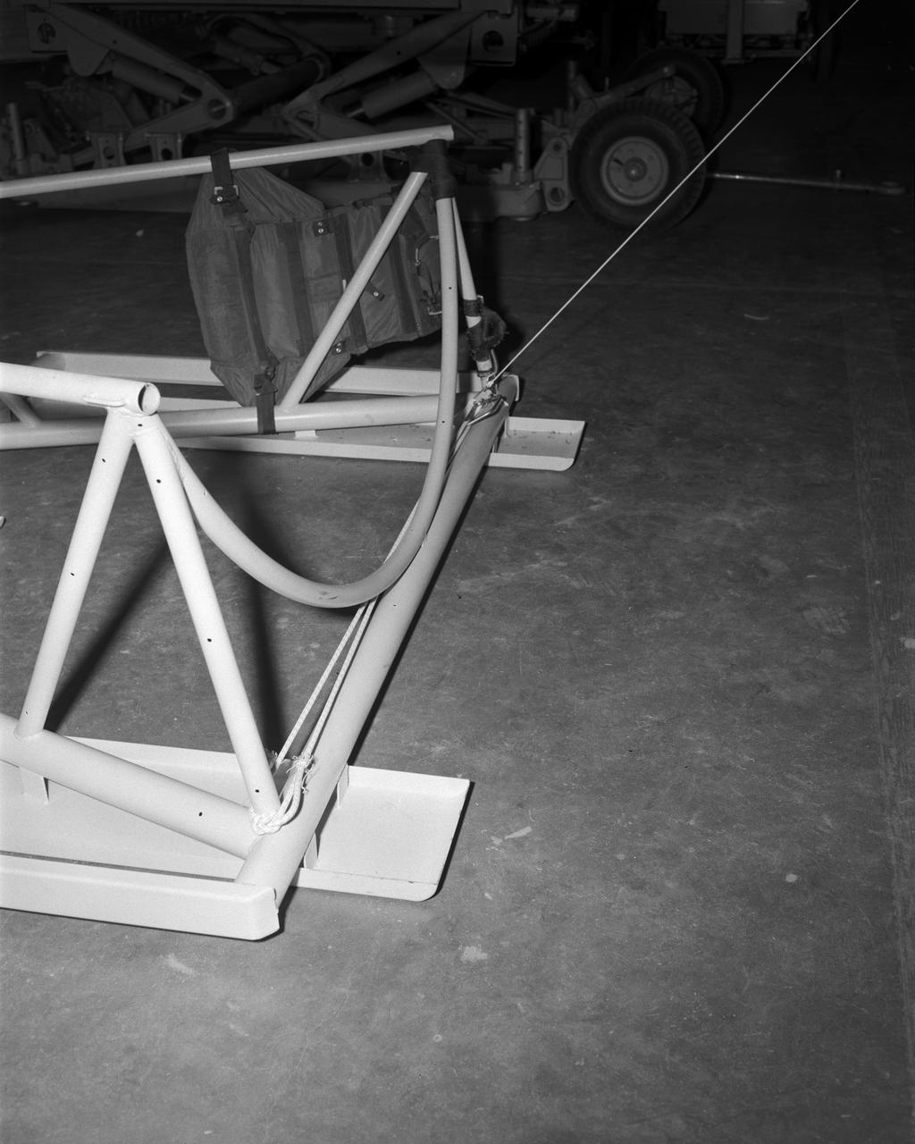
Technicians attach the escape tower to the Mercury capsule prior to assembly with Little Joe launcher, August 20, 1959. Joseph Shortal describe this as follows (vol. 3., p. 33): The escape tower and rocket motors were taken from the Mercury capsule production. The tower is shown being attached to the capsule.... The escape rocket was a Grand Central 1-KS-52000 motor with three canted nozzles. The tower-jettison motor was an Atlantic Research Corp. 1.4-KS-785 motor. This was the same design tested in a beach abort test...and had the offset thrust line as used in the beach abort test to insure that the capsule would get away from the booster in an emergency. The escape system weighed 1,015 pounds, including 236 pounds of ballast for stability. The Little Joe booster was assembled at Wallops on its special launcher in a vertical attitude. It is shown in the on the left with the work platform in place. The launcher was located on a special concrete slab in Launching Area 1. The capsule was lowered onto the booster by crane.... After the assembly was completed, the scaffolding was disassembled and the launcher pitched over to its normal launch angle of 80 degrees.... Little Joe had a diameter of 80 inches and an overall length, including the capsule and escape tower of 48 feet. The total weight at launch was about 43,000 pounds. The overall span of the stabilizing fins was 21.3 feet. Although in comparison with the overall Mercury Project, Little Joe was a simple undertaking, the fact that an attempt was made to condense a normal two-year project into a 6-month one with in house labor turned it into a major undertaking for Langley. -- Published in Joseph A. Shortal, History of Wallops Station: Origins and Activities Through 1949, (Wallops Island, VA: National Aeronautics and Space Administration, Wallops Station, nd), Comment Edition.
Model of Mercury (Redstone booster) carrying the spacecraft in the Unitary Plan wind tunnel for testing.

L59-3802 Nike-Cajun sounding rocket with University of Iowa payload on launcher at Wallops for flight test, May 20, 1959. Photograph published in A New Dimension Wallops Island Flight Test Range: The First Fifteen Years by Joseph Shortal. A NASA publication. Page 698.
Mercury capsule in Spin Tunnel
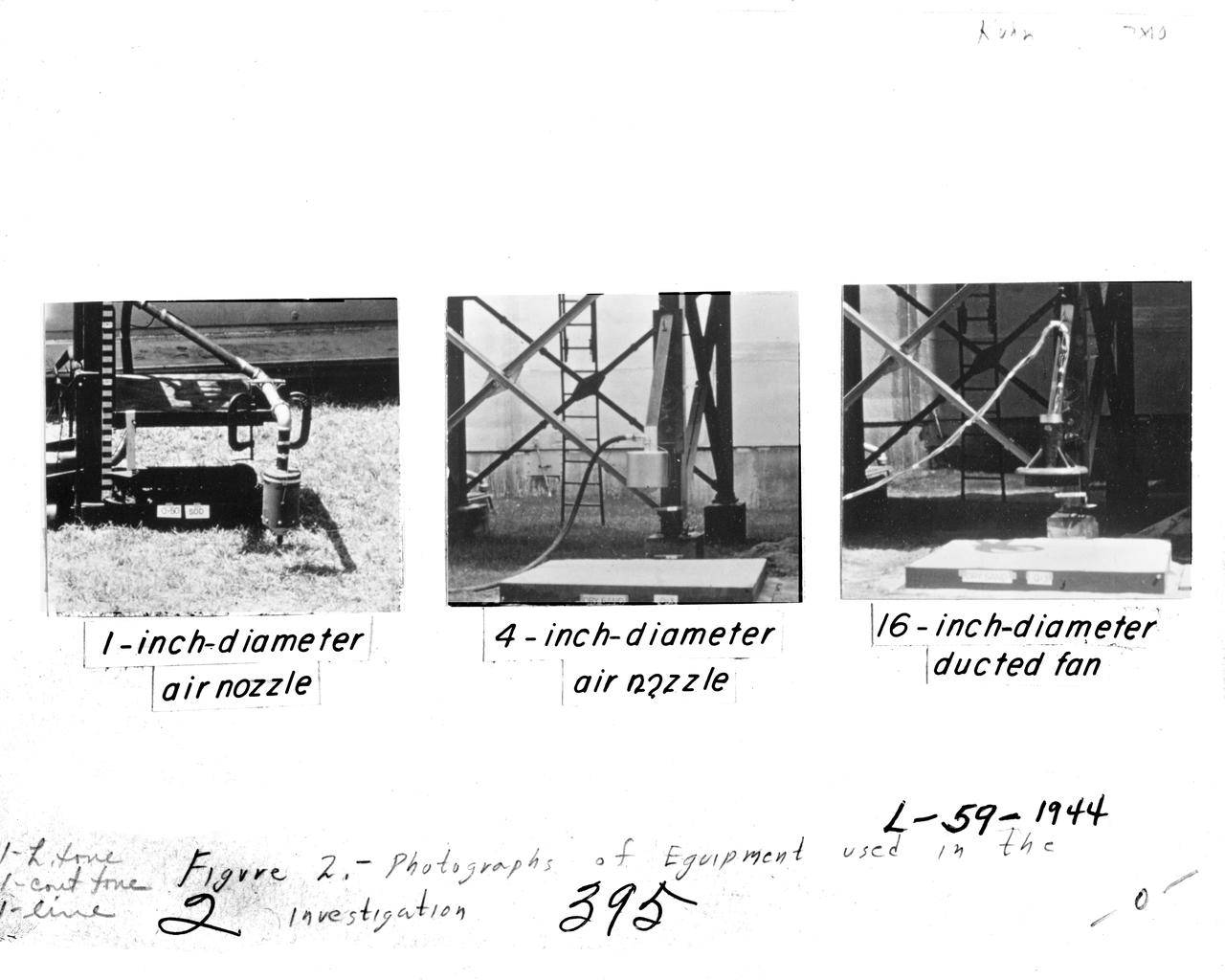
Image for NASA Document NASA-TN-D-56. Equipment Used In Investigation. Document Title: An investigation to determine conditions under which downwash from VTOL aircraft will start surface erosion from various types of terrain Figure 2. Equipment Used In Investigation
Space Flight Charts, Space Capsule
Air Bearings and Stable Platform
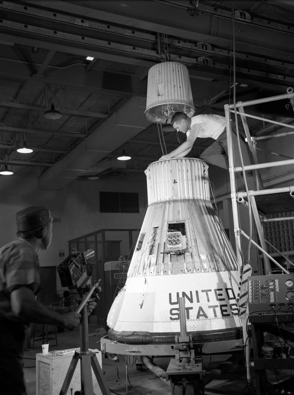
Technicians adjust the rocket motor during the attachment of the escape tower to the Mercury capsule prior to assembly with Little Joe launcher, August 20, 1959. Joseph Shortal wrote (vol. 3., p. 33): The escape tower and rocket motors were taken from the Mercury capsule production. The tower is shown being attached to the capsule.... The escape rocket was a Grand Central 1-KS-52000 motor with three canted nozzles. The tower-jettison motor was an Atlantic Research Corp. 1.4-KS-785 motor. This was the same design tested in a beach abort test...and had the offset thrust line as used in the beach abort test to insure that the capsule would get away from the booster in an emergency. The escape system weighed 1,015 pounds, including 236 pounds of ballast for stability. The Little Joe booster was assembled at Wallops on its special launcher in a vertical attitude. It is shown in the on the left with the work platform in place. The launcher was located on a special concrete slab in Launching Area 1. The capsule was lowered onto the booster by crane.... After the assembly was completed, the scaffolding was disassembled and the launcher pitched over to its normal launch angle of 80 degrees.... Little Joe had a diameter of 80 inches and an overall length, including the capsule and escape tower of 48 feet. The total weight at launch was about 43,000 pounds. The overall span of the stabilizing fins was 21.3 feet. Although in comparison with the overall Mercury Project, Little Joe was a simple undertaking, the fact that an attempt was made to condense a normal two-year project into a 6-month one with in house labor turned it into a major undertaking for Langley. -- Published in Joseph A. Shortal, History of Wallops Station: Origins and Activities Through 1949, (Wallops Island, VA: National Aeronautics and Space Administration, Wallops Station, nd), Comment Edition.
Blunt Leading Edge Model in the Unitary Wind Tunnel high mach number test section.
HSC Model 154 Dyna Soar (Martin-Bell)
Boost glide model
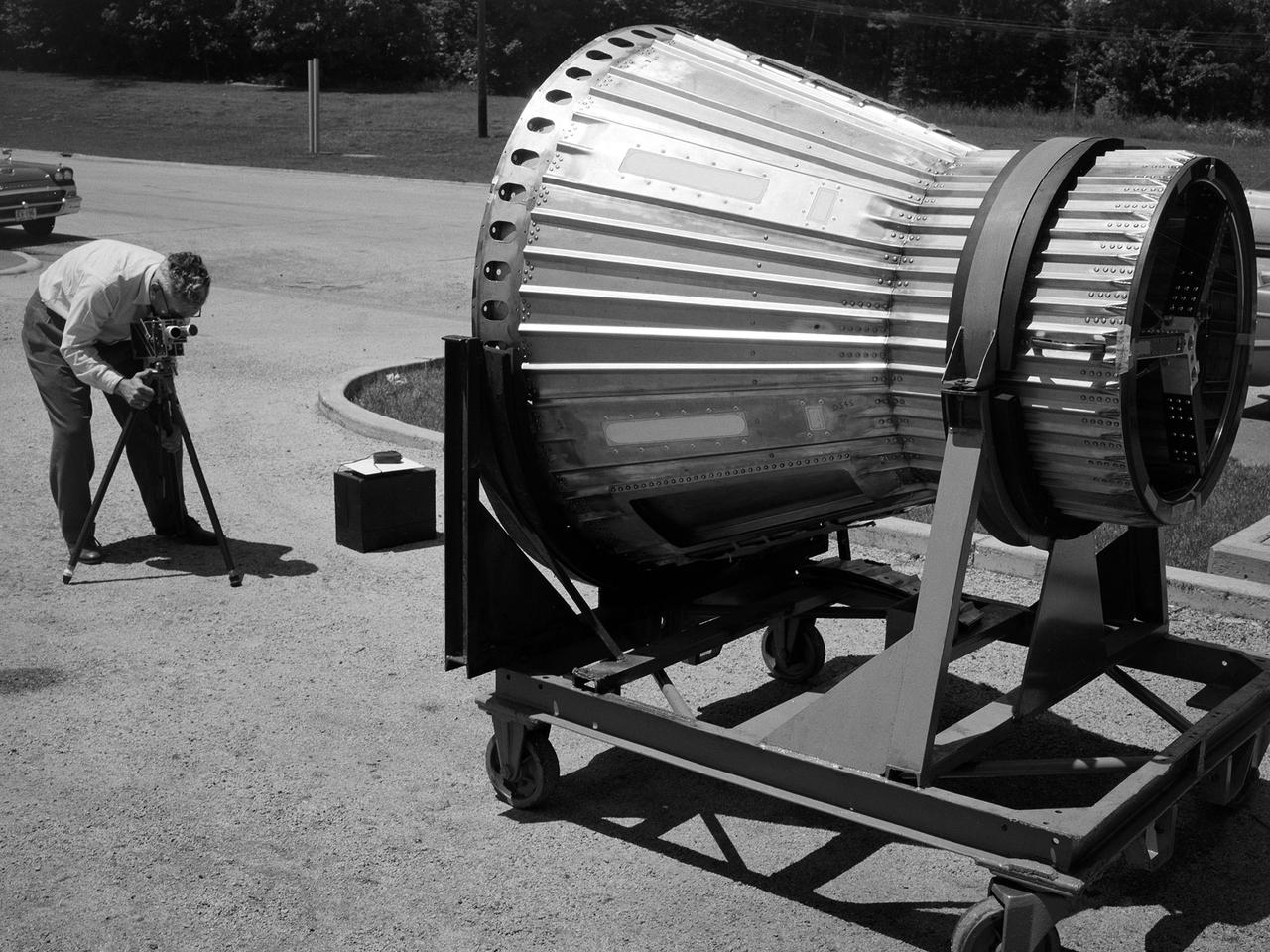
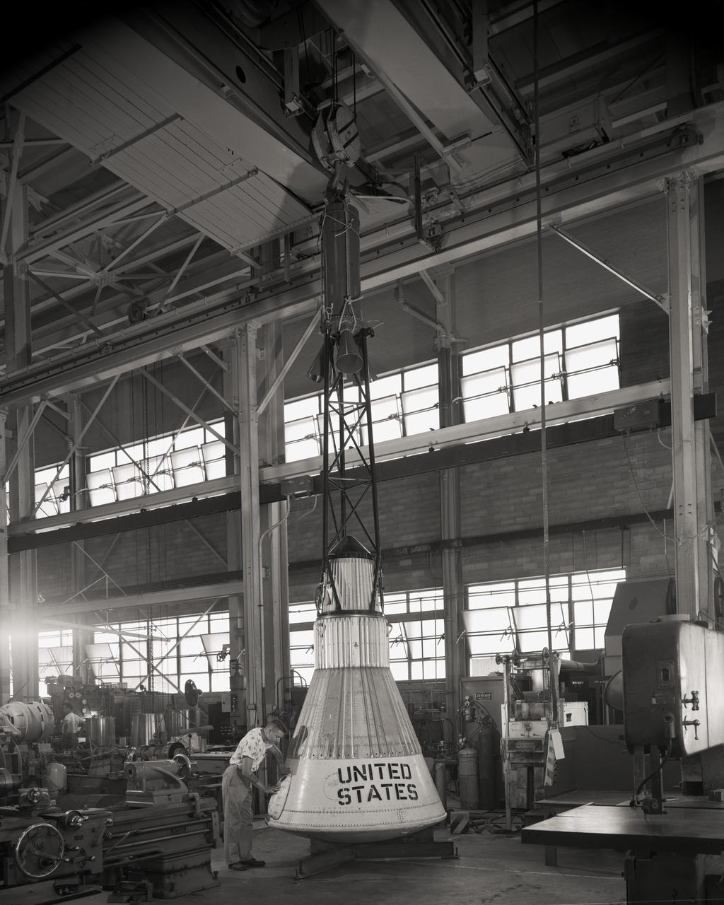
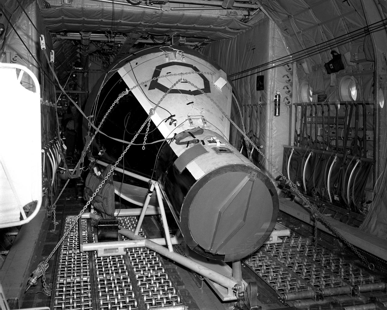
National Aeronautics and Space Administration (NASA) photographer Arthur Laufman sets up a camera to film a Mercury capsule that was constructed by the Lewis Research Center staff. Lewis engineers and mechanics built two of the capsules for the upcoming Big Joe launches in September 1959. Big Joe was an attempt early in Project Mercury to use a full-scale Atlas booster to simulate the reentry of a mock-up Mercury capsule without actually placing it in orbit. The Photographic Branch, referred to as the Photo Lab, was part of the center’s Technical Reports Division. Originally the group performed normal and high-speed still image and motion picture photography. The photographers documented construction, performed publicity work, created images for reports, photographed data on manometer boards, and recorded test footage. Laufman joined the Photo Lab staff in 1948 and began producing full-length technical films as a tool to educate those outside of the agency on the research being conducted at Lewis. He worked with engineers to determine proper subjects for these films and develop a script. Laufman not only filmed tests, but also supporting footage of facilities, models, and staff members. He then edited the footage and added audio, visuals, and narration. The film masters were assigned standard identification numbers and add to the Photo Lab’s catalogue.
Astronauts at 1959 Langley Inspection
L59-8368 Spherical 5 Inch rocket motor with radio beacon mounted as a torus around the nozzle. View shows motor as used in trailblazer I vehicles. Photograph published in A New Dimension Wallops Island Flight Test Range: The First Fifteen Years by Joseph Shortal. A NASA publication. Page 678.
Arcas Rocket B1-110
Martin-Bell Dyna Soar Model B.W.V
Technicians adjust the rocket motor during the attachment of the escape tower to the Mercury capsule prior to assembly with Little Joe launcher, August 20, 1959. Joseph Shortal wrote (vol. 3., p. 33): The escape tower and rocket motors were taken from the Mercury capsule production. The tower is shown being attached to the capsule.... The escape rocket was a Grand Central 1-KS-52000 motor with three canted nozzles. The tower-jettison motor was an Atlantic Research Corp. 1.4-KS-785 motor. This was the same design tested in a beach abort test...and had the offset thrust line as used in the beach abort test to insure that the capsule would get away from the booster in an emergency. The escape system weighed 1,015 pounds, including 236 pounds of ballast for stability. The Little Joe booster was assembled at Wallops on its special launcher in a vertical attitude. It is shown in the on the left with the work platform in place. The launcher was located on a special concrete slab in Launching Area 1. The capsule was lowered onto the booster by crane.... After the assembly was completed, the scaffolding was disassembled and the launcher pitched over to its normal launch angle of 80 degrees.... Little Joe had a diameter of 80 inches and an overall length, including the capsule and escape tower of 48 feet. The total weight at launch was about 43,000 pounds. The overall span of the stabilizing fins was 21.3 feet. Although in comparison with the overall Mercury Project, Little Joe was a simple undertaking, the fact that an attempt was made to condense a normal two-year project into a 6-month one with in house labor turned it into a major undertaking for Langley. -- Published in Joseph A. Shortal, History of Wallops Station: Origins and Activities Through 1949, (Wallops Island, VA: National Aeronautics and Space Administration, Wallops Station, nd), Comment Edition.
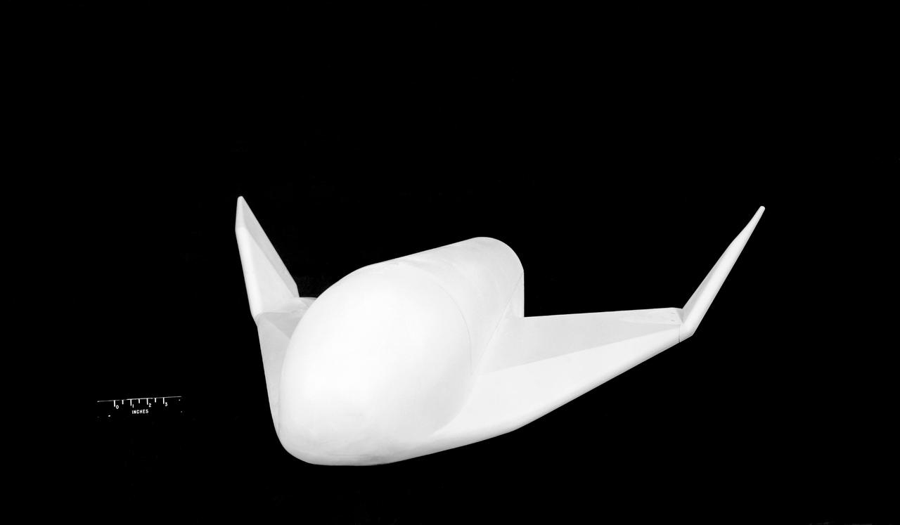
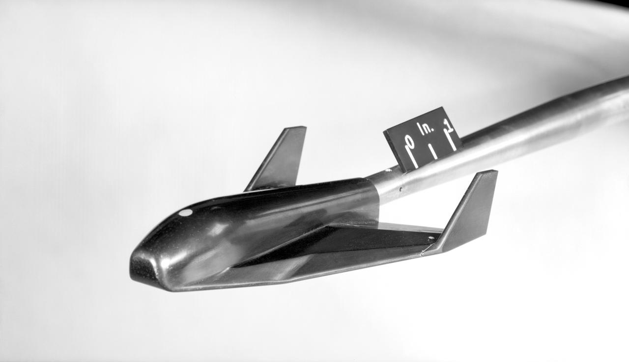
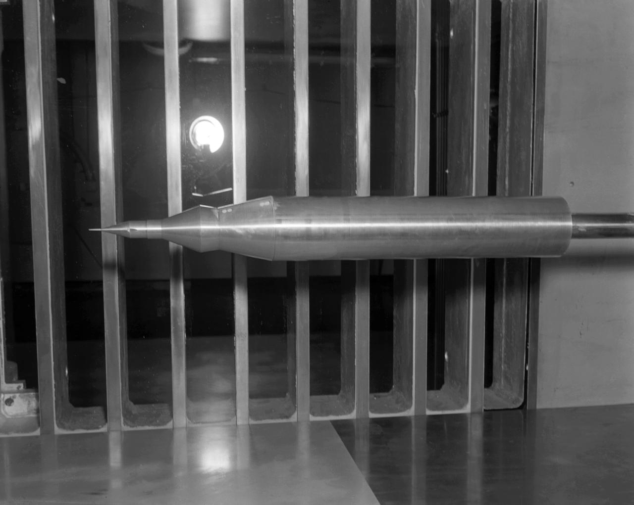
Lifting Type Re-Entry Vehicle
Molding of Space Couch
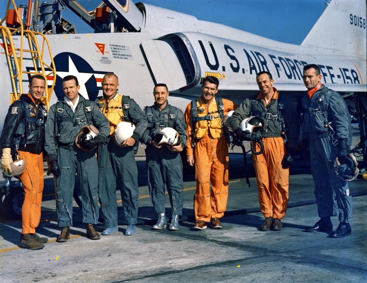
CAPE CANAVERAL, FLA. -- The Original Seven Mercury Astronauts pose beside an Air Force F-102 jet. Standing, left to right, are M. Scott Carpenter, L. Gordon Cooper, John H. Glenn Jr., Virgil I. 'Gus' Grissom, Walter M. Schirra Jr., Alan B. Shepherd Jr., and Donald K. 'Deke' Slayton.

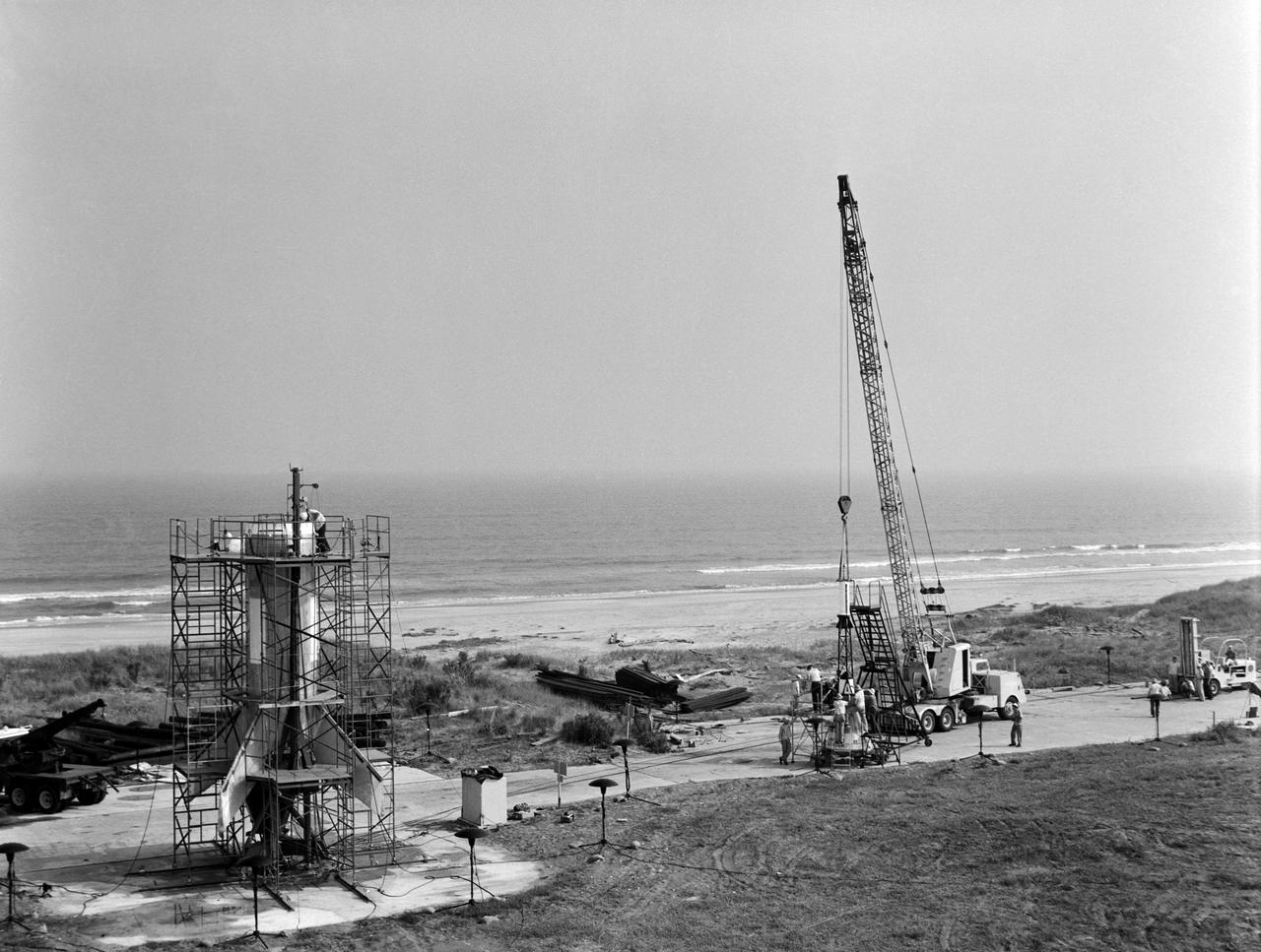
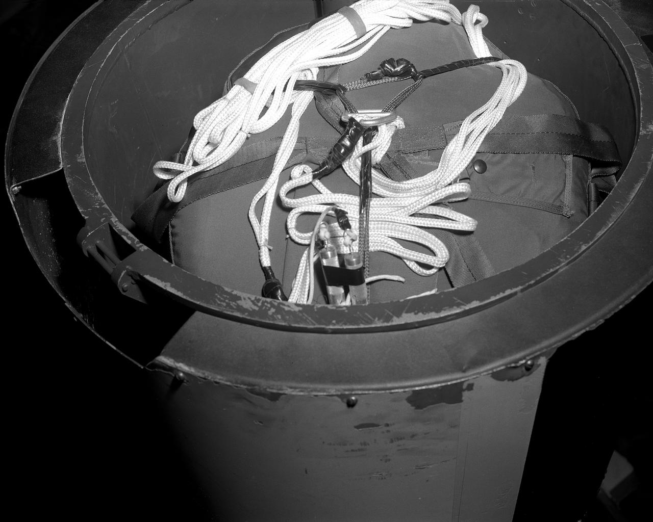
Caption: Off the pad abort shot at Wallops using Langley PARD designed full scale capsule with Recruit rocket and extended skirt main parachute. Shows sequential images of launch and capsule splashdown.
Jupiter (AM-18), suborbital primate flight with Able and Baker as its payload, being ready for launch, May 28, 1959
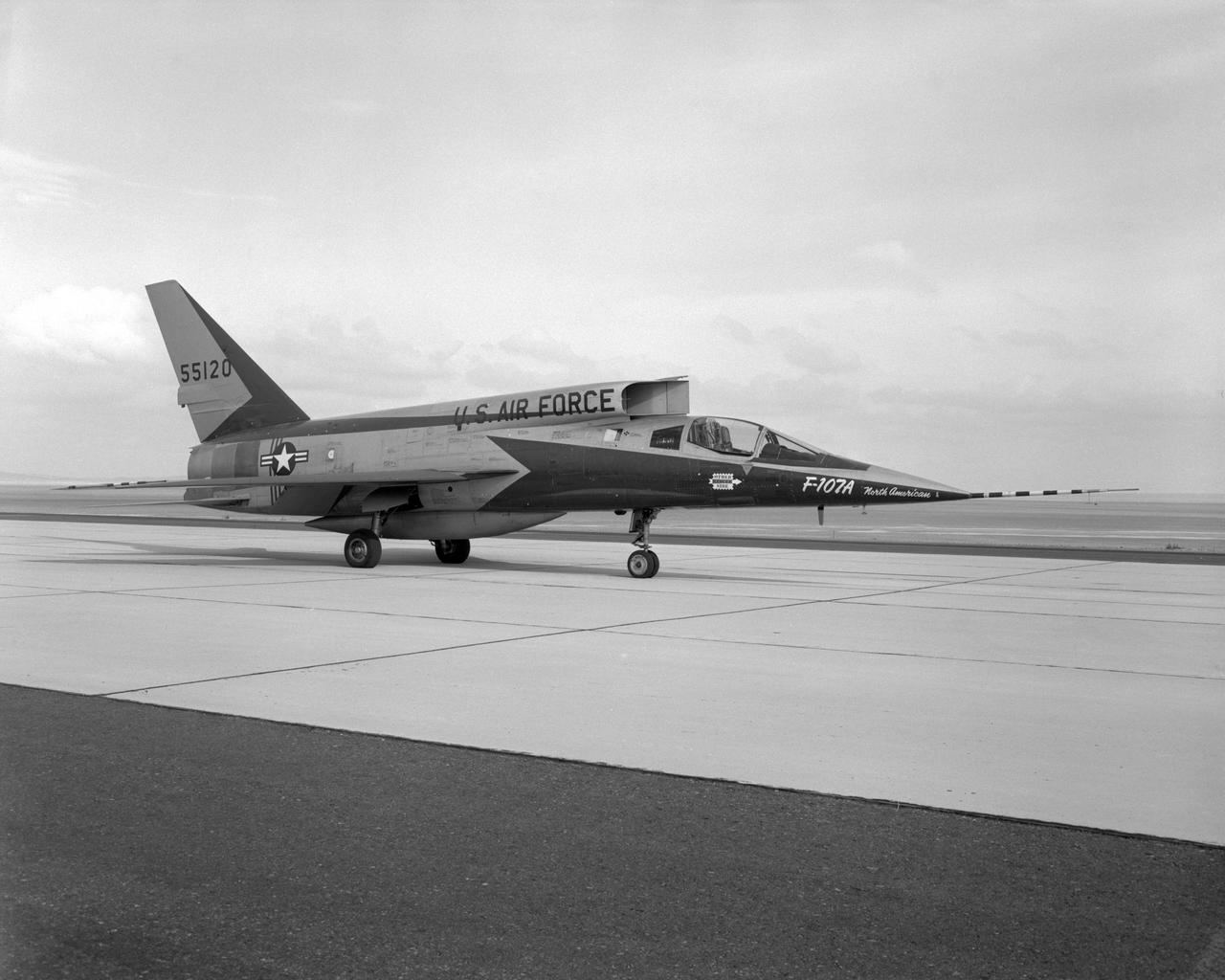
The third F-107A parked on the ramp at the Flight Research Center. Jan. 7, 1959
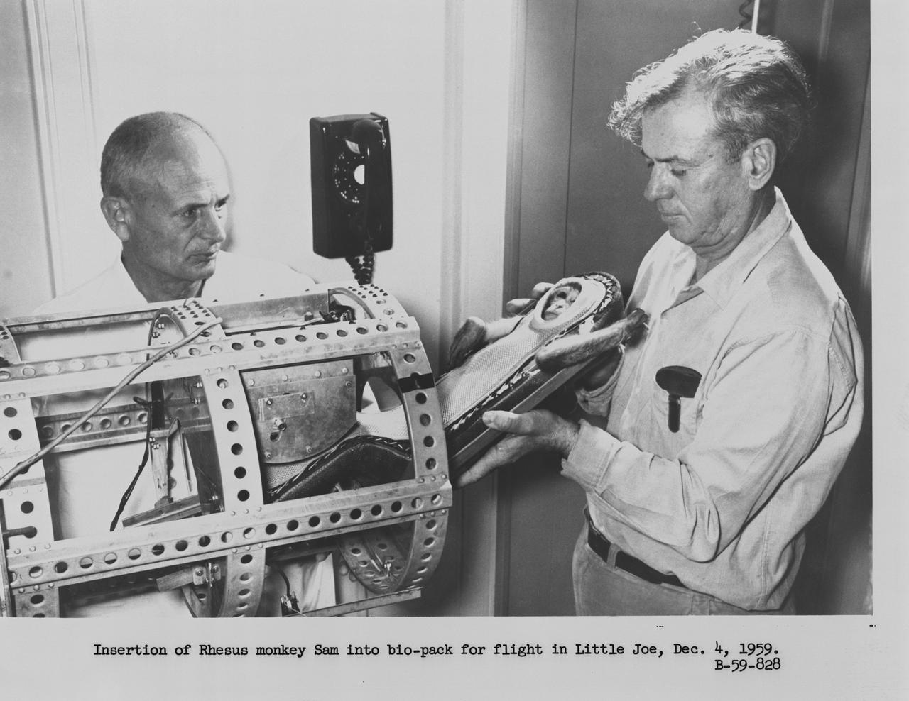
B59-00828 (21 Jan. 1959) --- The test subject, a rhesus monkey named Miss Sam, is seen encased in a model of the Mercury fiberglass contour couch. She is being placed in a container for the Little Joe 1B suborbital test flight of the Mercury Capsule. Photo credit: NASA
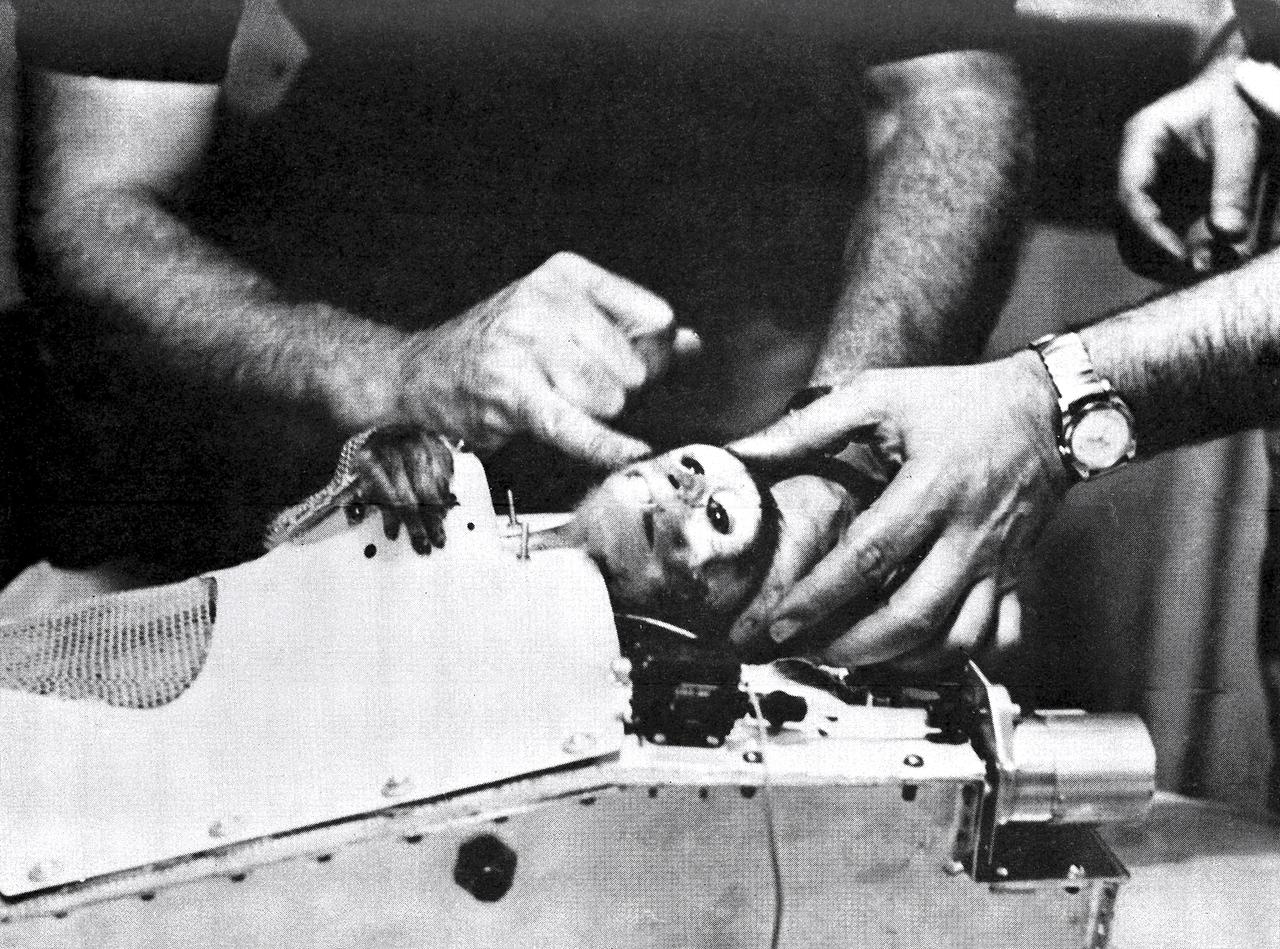
On May 28, 1959, a Jupiter Intermediate Range Ballistic Missile provided by a U.S. Army team in Redstone Arsenal, Alabama, launched a nose cone carrying Baker, A South American squirrel monkey and Able, An American-born rhesus monkey. This photograph shows Able after recovery of the nose cone of the Jupiter rocket by U.S.S. Kiowa.
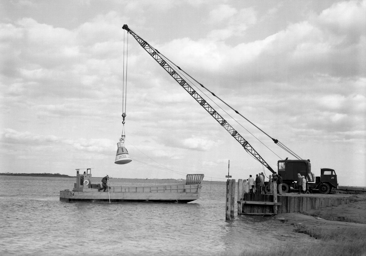
Water drop and recovery from shore-based crane at Langley's back river.
Vehicles and Missions Studies Charts, Space Capsule
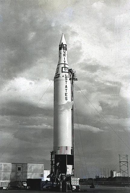
The Juno II launch vehicle, shown here, was a modified Jupiter Intermediate-Range Ballistic missionile, developed by Dr. Wernher von Braun and the rocket team at Redstone Arsenal in Huntsville, Alabama. Between December 1958 and April 1961, the Juno II launched space probes Pioneer III and IV, as well as Explorer satellites VII, VIII and XI.
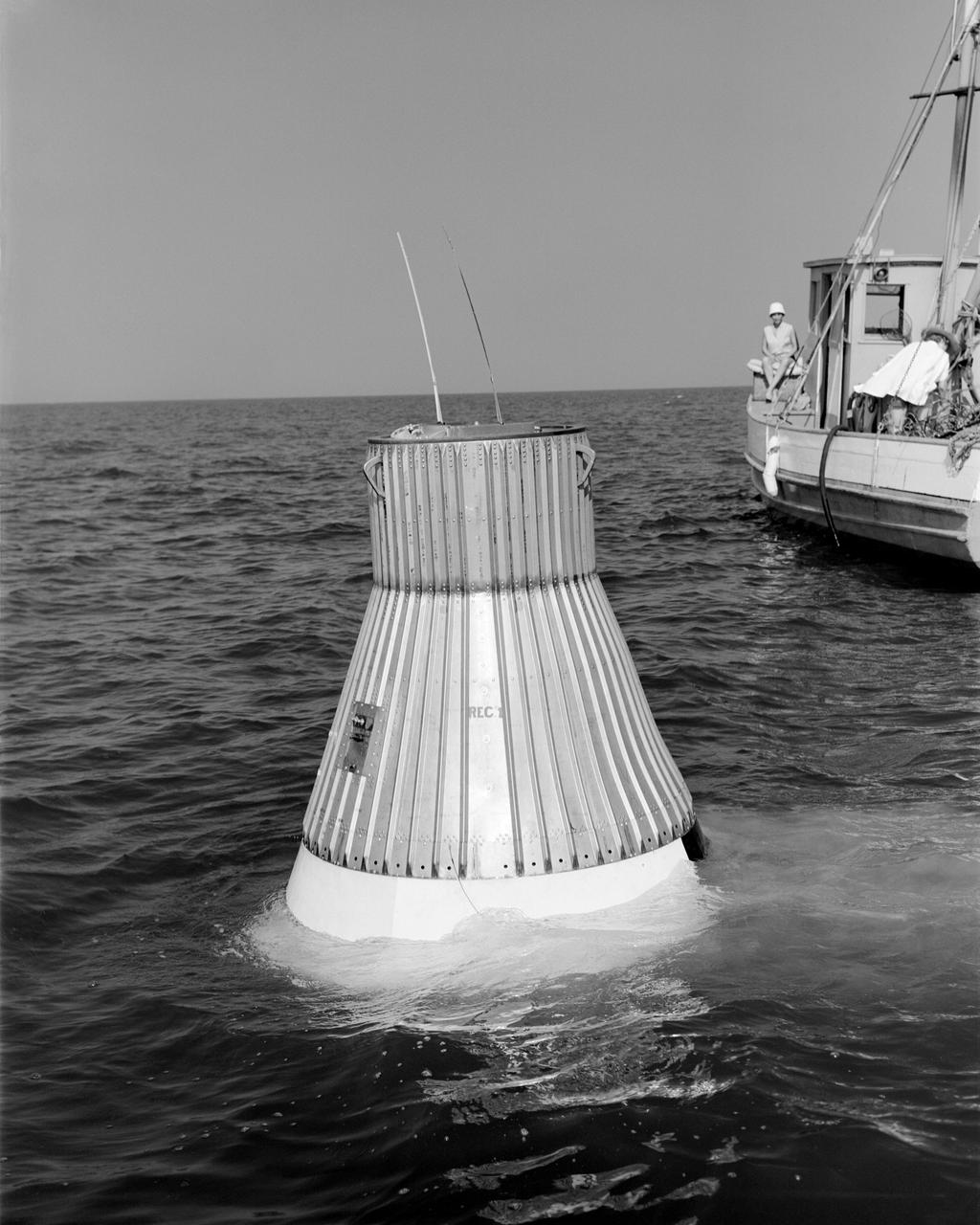
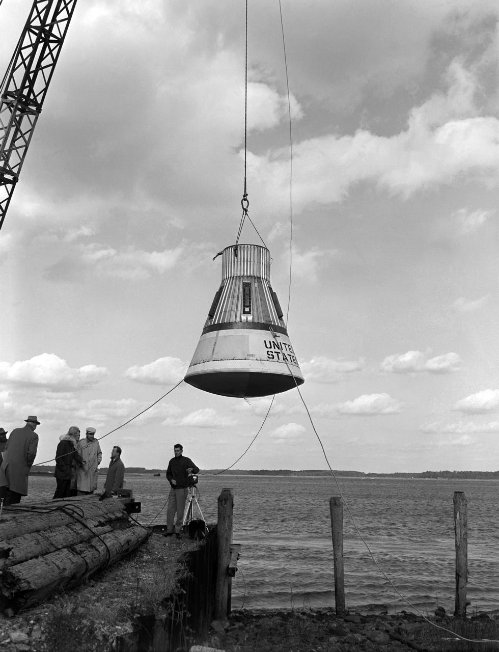
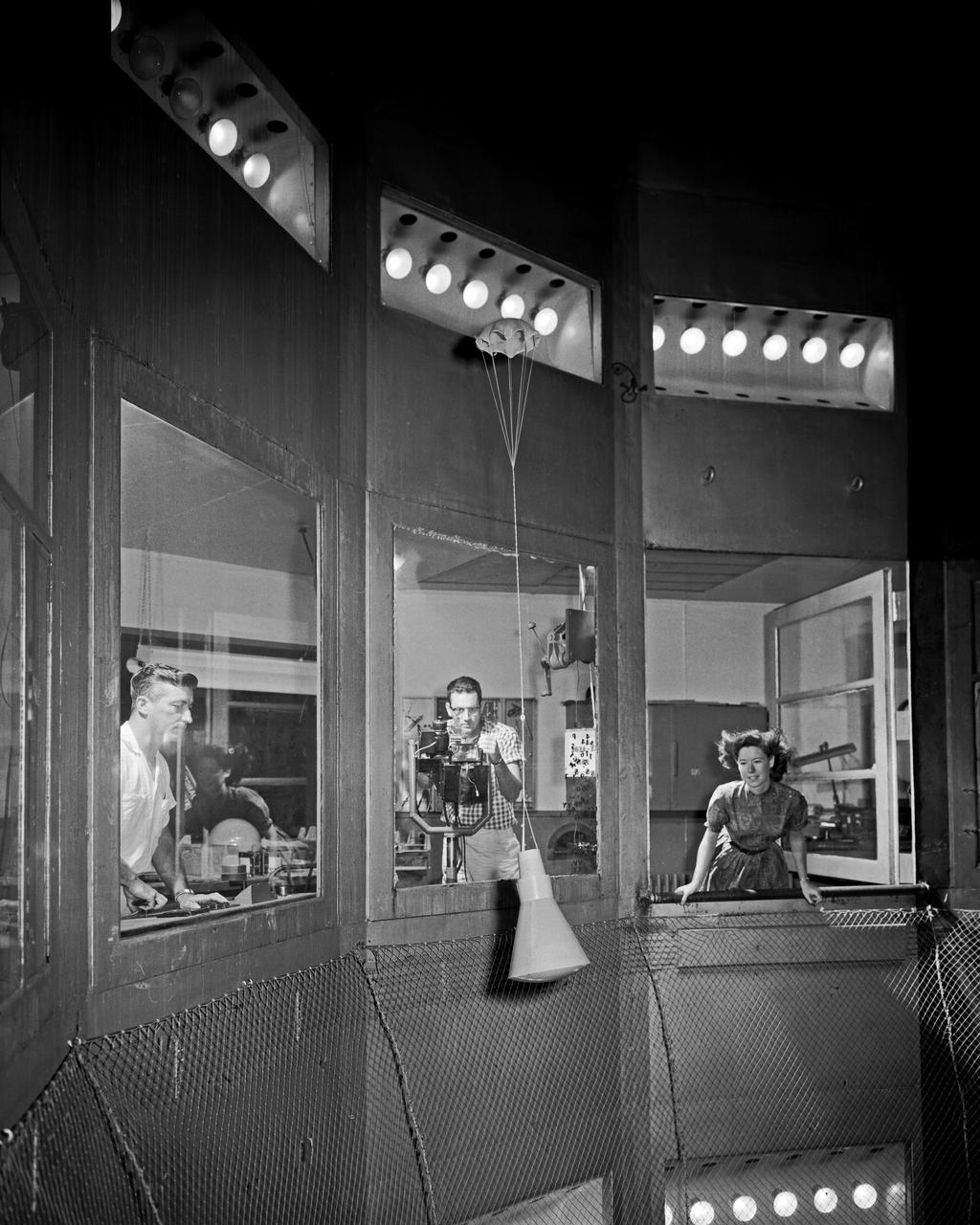
L59-4073 A model of the Mercury capsule undergoes flotation tests. -- Photograph published in Winds of Change, 75th Anniversary NASA publication (page 76), by James Schultz.
Space Flight Charts, Space Capsule
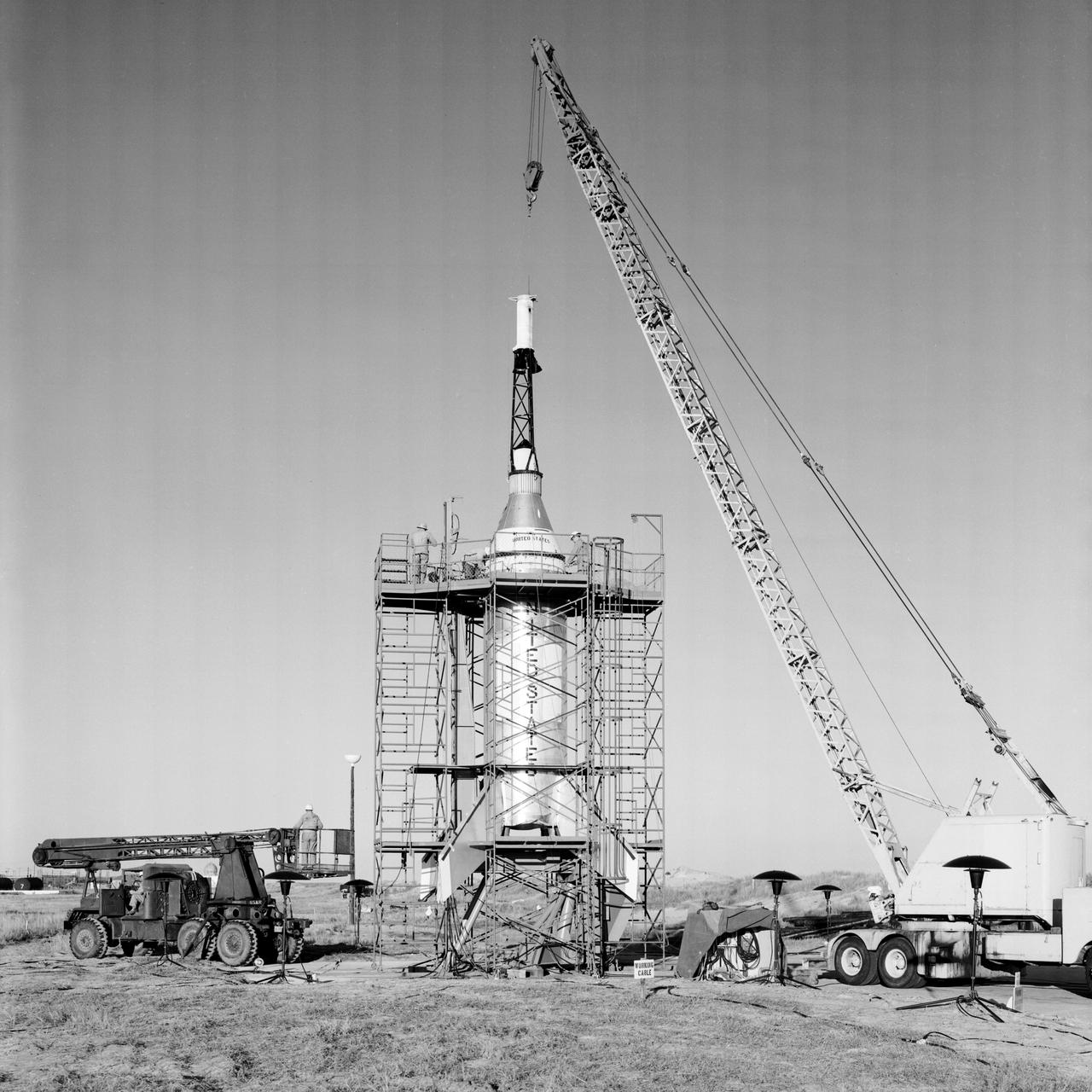
The Mercury capsule and escape tower are being lowered onto the Little Joe booster for launch on August 21, 1959. Joseph Shortal described this as follows (vol. 3, p. 33): The Little Joe booster was assembled at Wallops on its special launcher in a vertical attitude. It is shown in the on the left with the work platform in place. The launcher was located on a special concrete slab in Launching Area 1. The capsule was lowered onto the booster by crane.... After the assembly was completed, the scaffolding was disassembled and the launcher pitched over to its normal launch angle of 80 degrees.... Little Joe had a diameter of 80 inches and an overall length, including the capsule and escape tower of 48 feet. The total weight at launch was about 43,000 pounds. The overall span of the stabilizing fins was 21.3 feet. Although in comparison with the overall Mercury Project, Little Joe was a simple undertaking, the fact that an attempt was made to condense a normal two-year project into a 6-month one with in house labor turned it into a major undertaking for Langley. -- Published in Joseph A. Shortal, History of Wallops Station: Origins and Activities Through 1949, (Wallops Island, VA: National Aeronautics and Space Administration, Wallops Station, nd), Comment Edition.
Miscellaneous Charts, Space Capsule
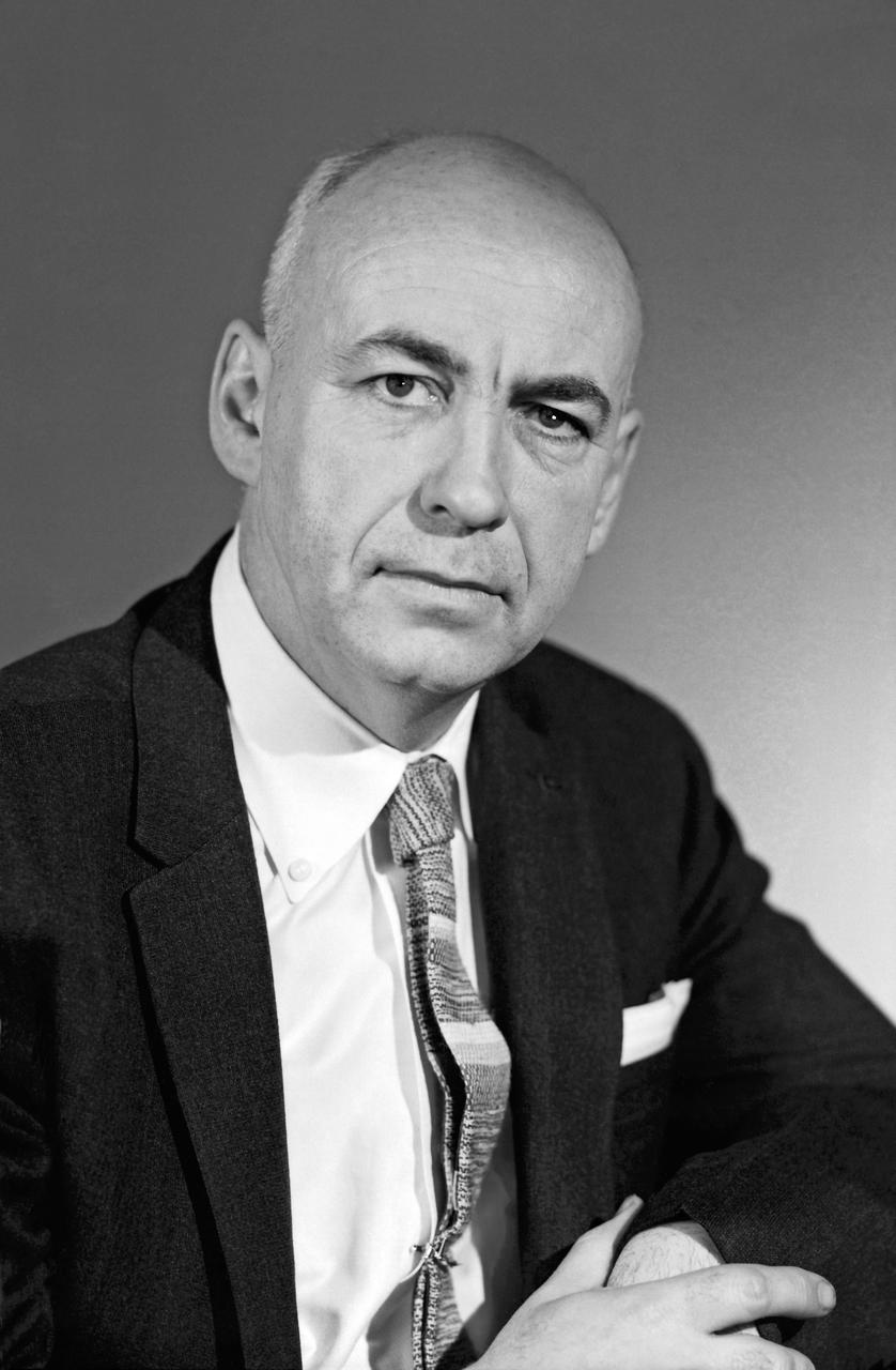
Portrait of Robert R. Gilruth. More than anyone else at Langley, began to push the idea that manned spaceflight was the next great challenge for aeronautic engineers. As head of NASA s Space Task Group, he was responsible for planning and carrying out Project Mercury, the country's first manned spaceflight program. Photograph published in Engineer in Charge: A History of the Langley Aeronautical Laboratory, 1917-1958 by James R. Hansen. Page 386.
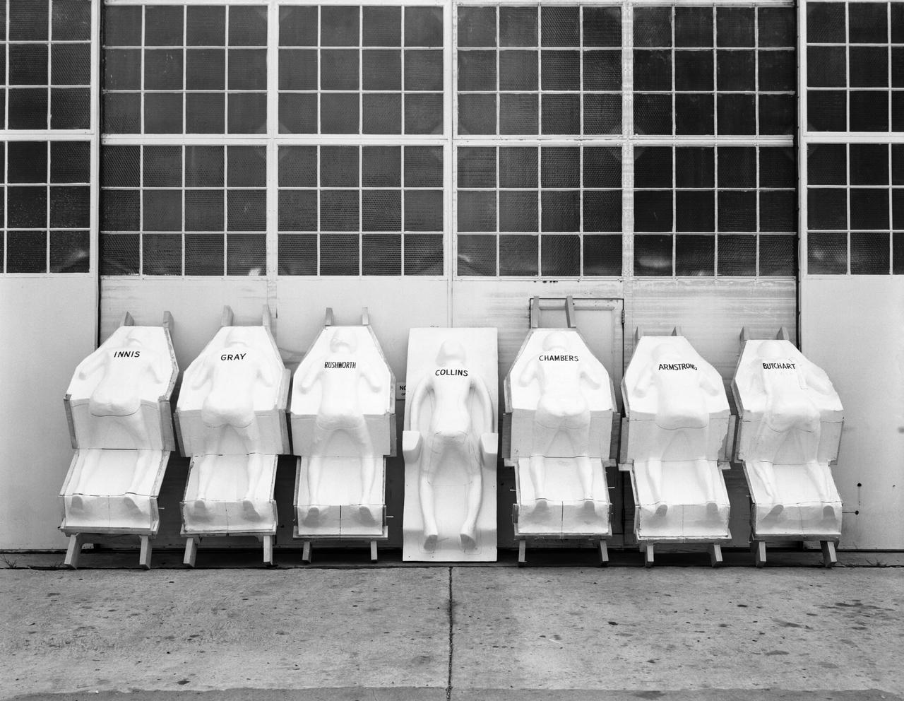
Molds for couches for test pilots, line the NASA Langley Research Centers model shop wall. The names of the test subjects (Langley employees) are written on the back. The couches are similar to those made for each astronaut and fitted into the Mercury capsules for manned spaceflight.
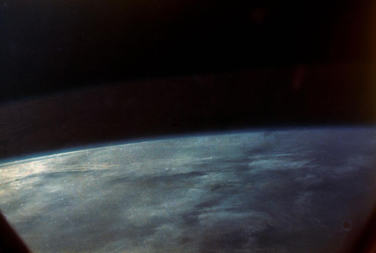
S62-06026 (20 Feb. 1962) --- View of Earth taken by astronaut John H. Glenn Jr. during his Mercury Atlas 6 (MA-6) spaceflight. Photo credit: NASA
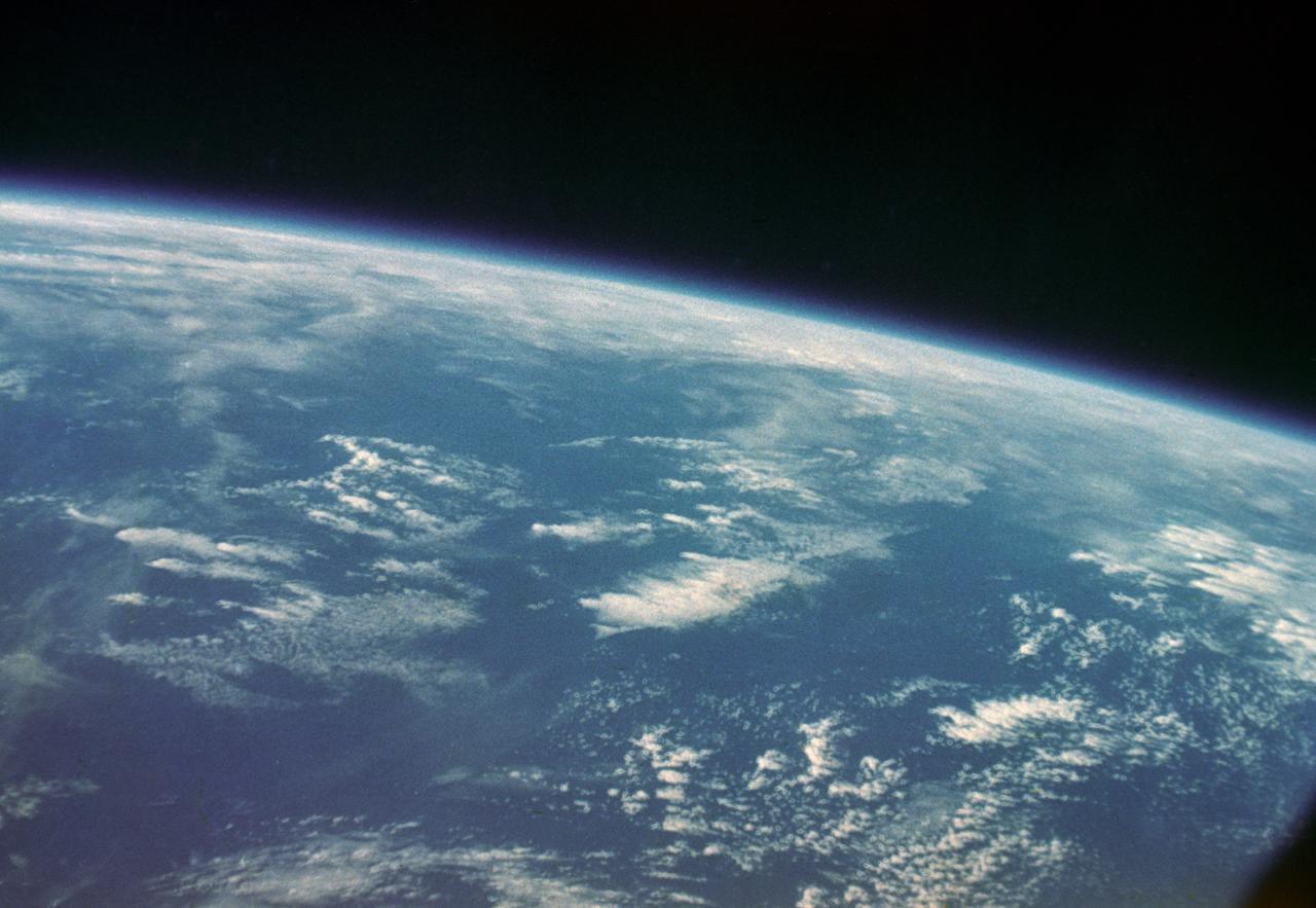
S62-06029 (20 Feb. 1962) --- View of Earth taken by astronaut John H. Glenn Jr. during his Mercury Atlas 6 (MA-6) spaceflight. Photo credit: NASA
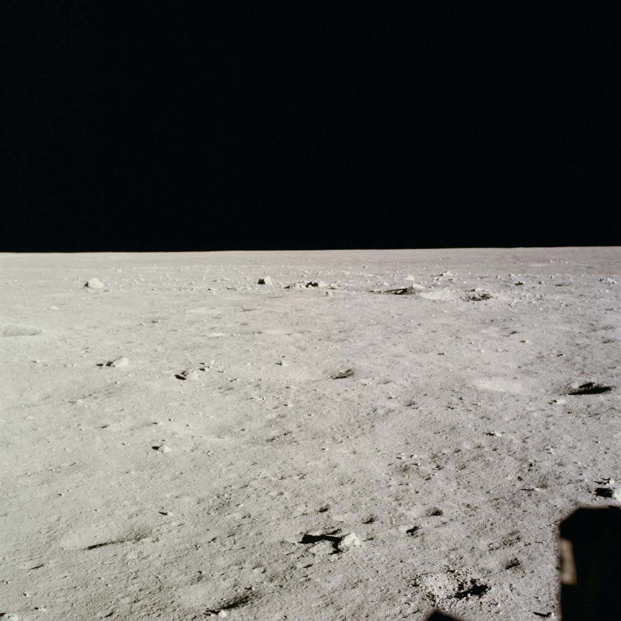
AS11-37-5458 (20 July 1969) --- This excellent view from the right-hand window of the Apollo 11 Lunar Module (LM) shows the surface of the moon in the vicinity of where the LM touched down. Numerous small rocks and craters can be seen between the LM and the lunar horizon. Astronaut Michael Collins, command module pilot, remained with the Command and Service Modules (CSM) in lunar orbit while astronauts Neil A. Armstrong, commander; and Edwin E. Aldrin Jr., lunar module pilot, descended in the LM to the lunar surface.
Miscellaneous Charts, Space Capsule
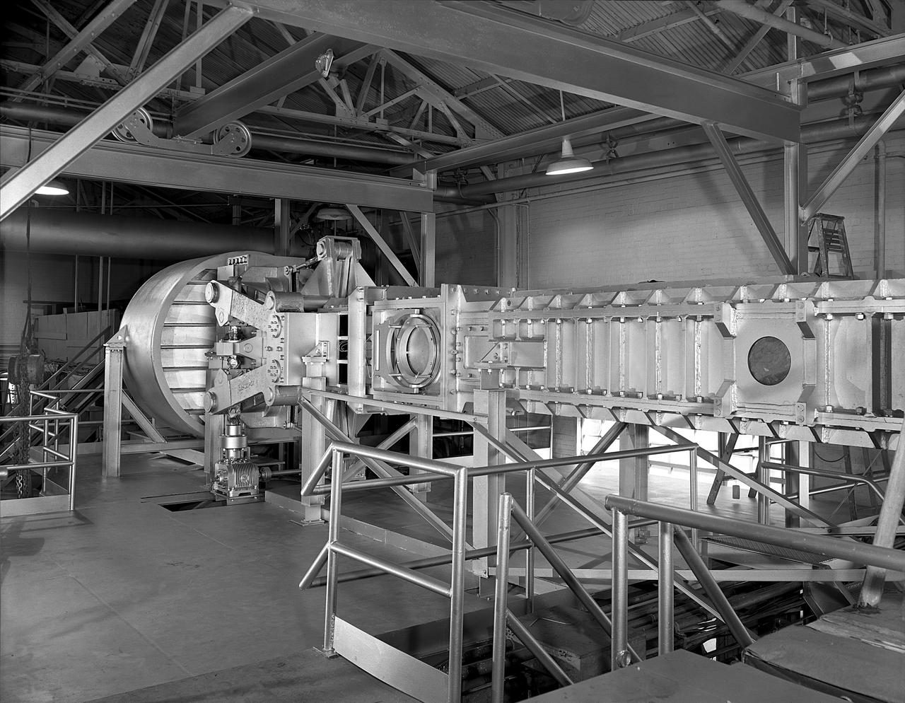
The first circumferential welding being applied on a Saturn fuel container in the Army Ballistic Missile Agency (ABMA) fabrication laboratory, Building 4707, in May 1959.
Miscellaneous Charts, Space Capsule

Air Force Javelin Rocket on Launcher (USAF JV-1) Wallops Model D4-78 L59-5144 First AFSWC Javelin sounding rocket ready for flight test, July 7, 1959. Photograph published in A New Dimension Wallops Island Flight Test Range: The First Fifteen Years by Joseph Shortal. A NASA publication. Page 704.
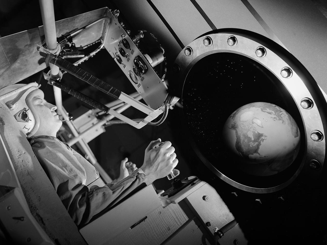
This composite image includes a photograph of pilot Joe Algranti testing the Multi-Axis Space Test Inertia Facility (MASTIF) inside Altitude Wind Tunnel at NASA’s Lewis Research Center with other images designed to simulate the interior of a Mercury space capsule. As part of the space agency’s preparations for Project Mercury missions, the seven Mercury astronauts traveled to Cleveland in early 1960 to train on the MASTIF. Researchers used the device to familiarize the astronauts with the sensations of an out-of-control spacecraft. The MASTIF was a three-axis rig with a pilot’s chair mounted in the center. An astronaut was secured in a foam couch in the center of the rig. The rig then spun on three axes from 2 to 50 rotations per minute. The astronauts used small nitrogen gas thrusters to bring the MASTIF under control. In the fall of 1959, prior to the astronauts’ visit, Lewis researcher James Useller and Algranti perfected and calibrated the MASTIF.
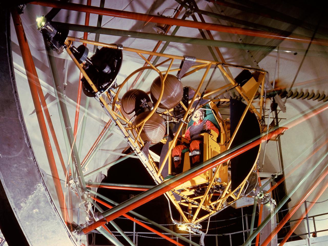
National Aeronautics and Space Administration (NASA) pilot Joe Algranti tests the Multi-Axis Space Test Inertia Facility (MASTIF) inside the Altitude Wind Tunnel while researcher Robert Miller looks on. The MASTIF was a three-axis rig with a pilot’s chair mounted in the center to train Project Mercury pilots to bring a spinning spacecraft under control. An astronaut was secured in a foam couch in the center of the rig. The rig then spun on three axes from 2 to 50 rotations per minute. Small nitrogen gas thrusters were used by the astronauts to bring the MASTIF under control. The device was originally designed in early 1959 without the chair and controllers. It was used by Lewis researchers to determine if the Lewis-designed autopilot system could rectify the capsule’s attitude following separation. If the control system failed to work properly, the heatshield would be out of place and the spacecraft would burn up during reentry. The system was flight tested during the September 1959 launch of the Lewis-assembled Big Joe capsule. The MASTIF was adapted in late 1959 for the astronaut training. NASA engineers added a pilot’s chair, a hand controller, and an instrument display to the MASTIF in order familiarize the astronauts with the sensations of an out-of-control spacecraft. NASA Lewis researcher James Useller and Algranti perfected and calibrated the MASTIF in the fall of 1959. In February and March 1960, the seven Project Mercury astronauts traveled to Cleveland to train on the MASTIF.
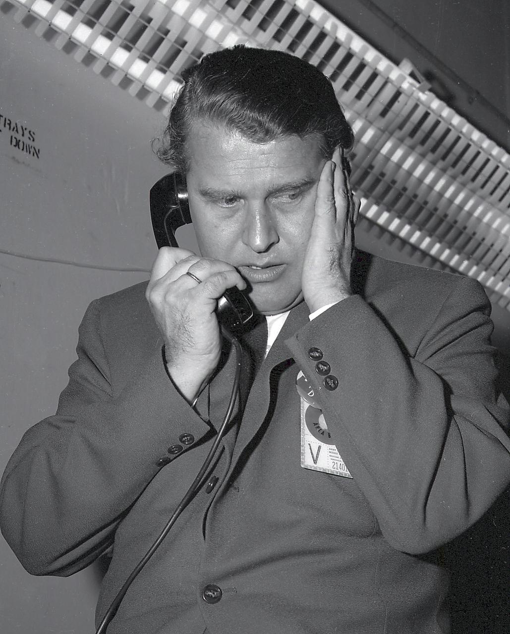
Dr. von Braun on the telephone prior to the launch of the Pioneer IV, March 1, 1959.

L59-7932 First University of Michigan Strongarm sounding rocket on launcher at Wallops for test, November 10, 1959. Photograph published in A New Dimension Wallops Island Flight Test Range: The First Fifteen Years by Joseph Shortal. A NASA publication. Page 701.E5-188 Shop and Launcher Pictures
20 Inch Variable Supersonic Tunnel G.A.S. Variable Mach Tunnel
Astronauts at 1959 Langley Inspection
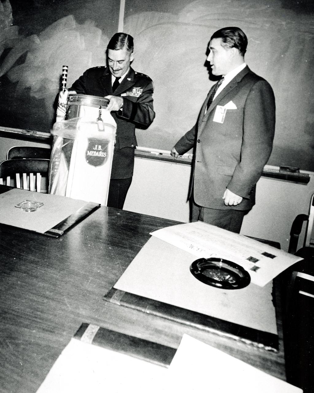
Marshall Space Flight Center Director Wernher von Braun presents General J.B. Medaris with a new golf bag. General Medaris, (left) was a Commander of the Army Ballistic Missile Agency (ABMA) in Redstone Arsenal, Alabama during 1955 to 1958.
Space Flight Charts, Space Capsule
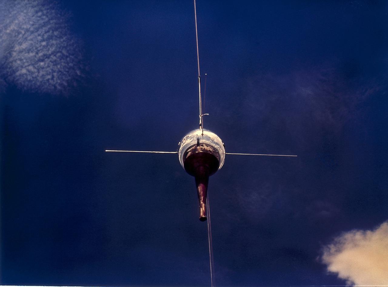
Installing Pioneer IV, payload for AM-14 (Juno II) onto the fourth stage on the cluster before a spin test, February 16, 1959. The Pioneer IV, lunar and planetary exploration satellite, was the first U.S. satellite to orbit the Sun.
Mercury capsule in Spin Tunnel
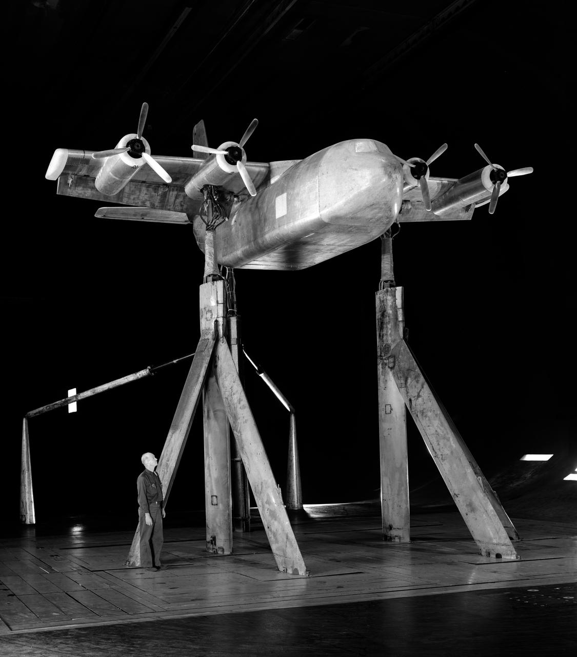
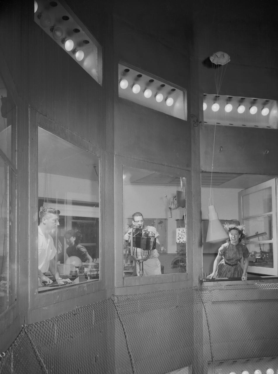
4 propeller Tilt Wing. Pictured with Tommy Wills wind tunnel mechanic in the 40x80 foot wind tunnel.
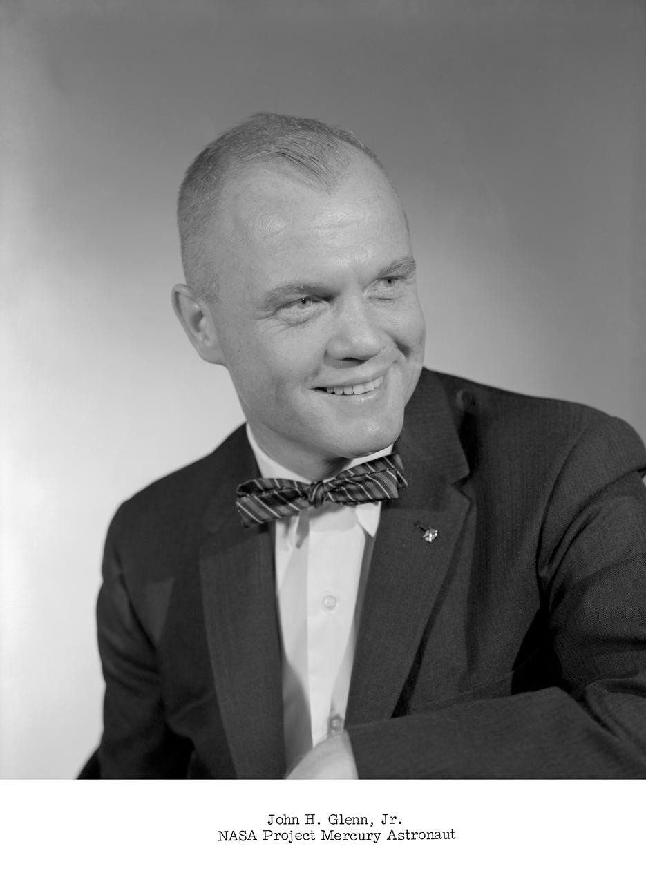
NASA Project Mercury astronaut.
Space Flight Charts, Space Capsule
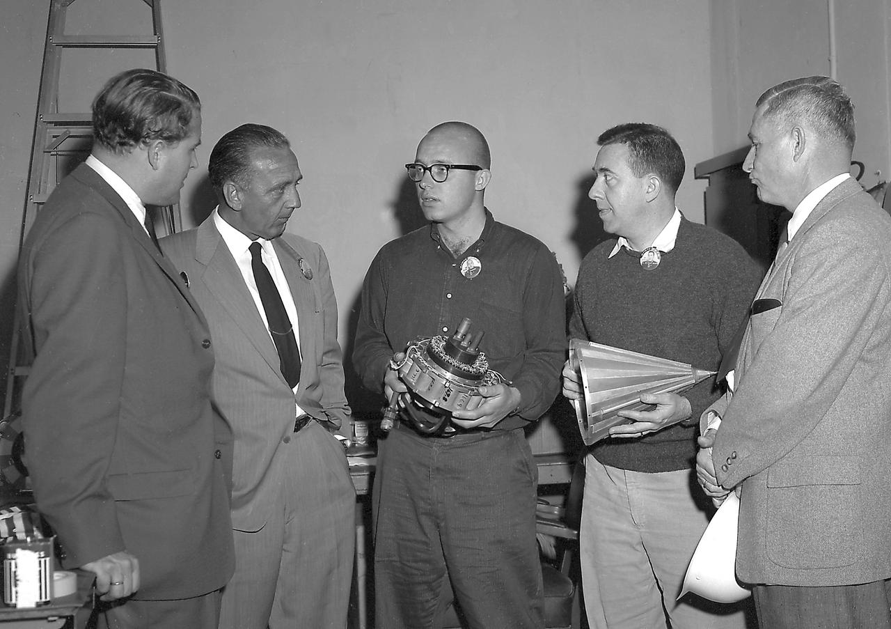
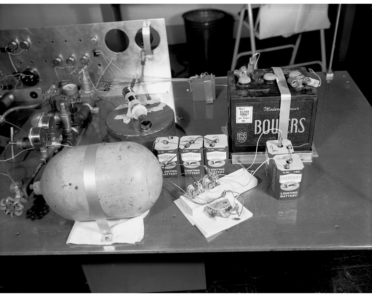
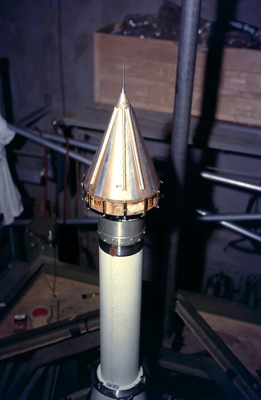
In this photo, Director of the U.S. Army Ballistic Missile Agency's (ABMA) Development Operations Division, Dr. Wernher von Braun, and Director of Missile Firing Division, Dr. Kurt Debus, are shown with unidentified individuals, discussing two components that would make up the Pioneer IV Lunar Probe. The mercury batteries (left) were used to power the radio transmitter, cosmic radiation counter and other instruments in Pioneer IV. The conical shroud placed over the instruments of Pioneer IV was plated with gold to improve conductivity. The metal surface also served as the anterna for the probe's instruments signaling back to the Earth receiving stations.
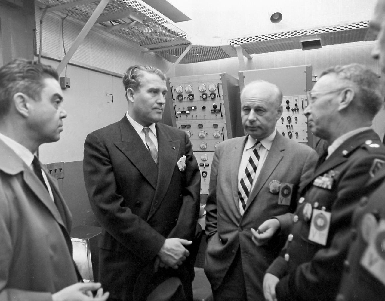
In this 1959 photo, taken at Cape Canaveral, Florida, Dr. von Braun (2nd from left) Director of the U.S. Army Ballistic Missile Agency's (ABMA) Development Operations Division, is shown conferring with Air Force Major General Donald R. Ostrander (left), on assignment at NASA as launch vehicle director; Dr. Eberhard Rees, deputy to Dr. von Braun, and Army Brigadier General John Barclay, commander of the ABMA.