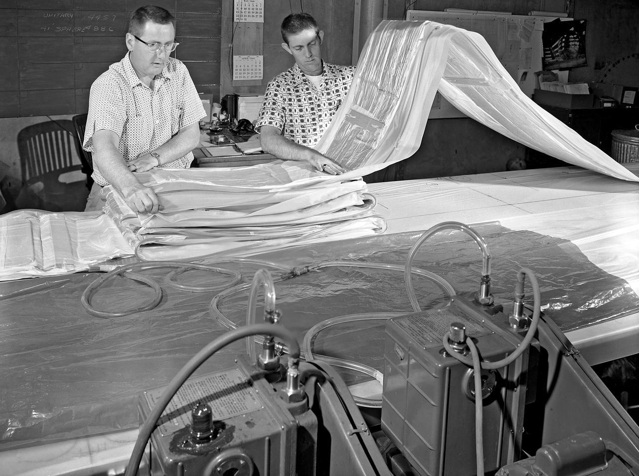
100' Satellite Packaging of Echo
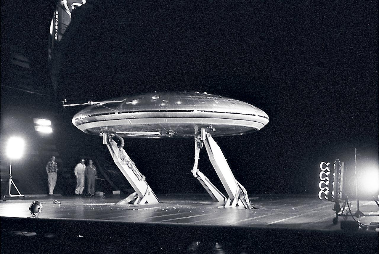
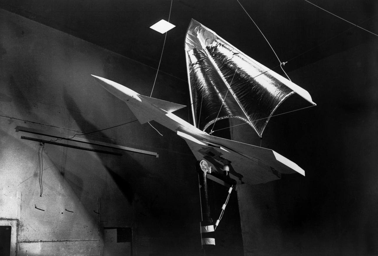
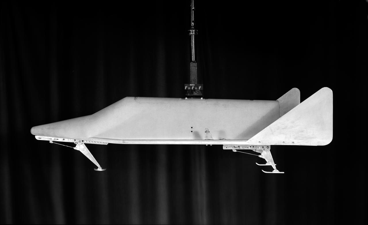
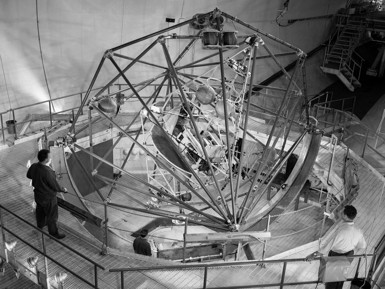
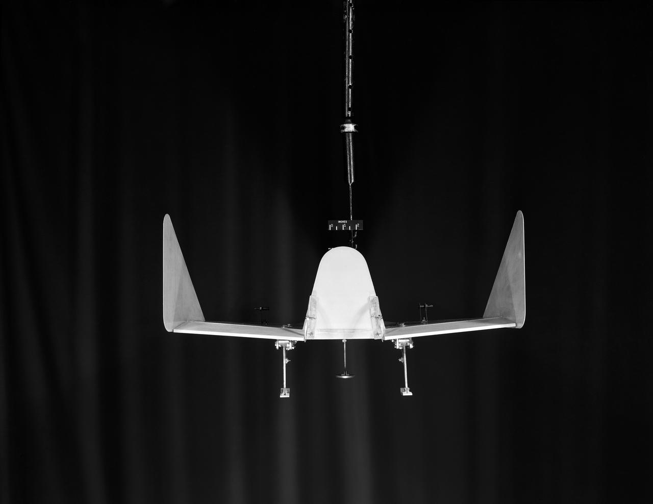
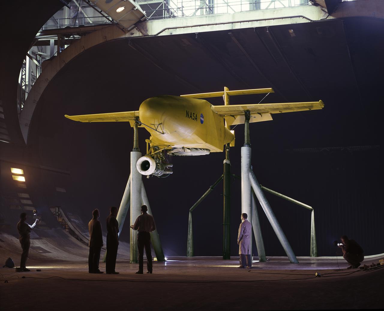
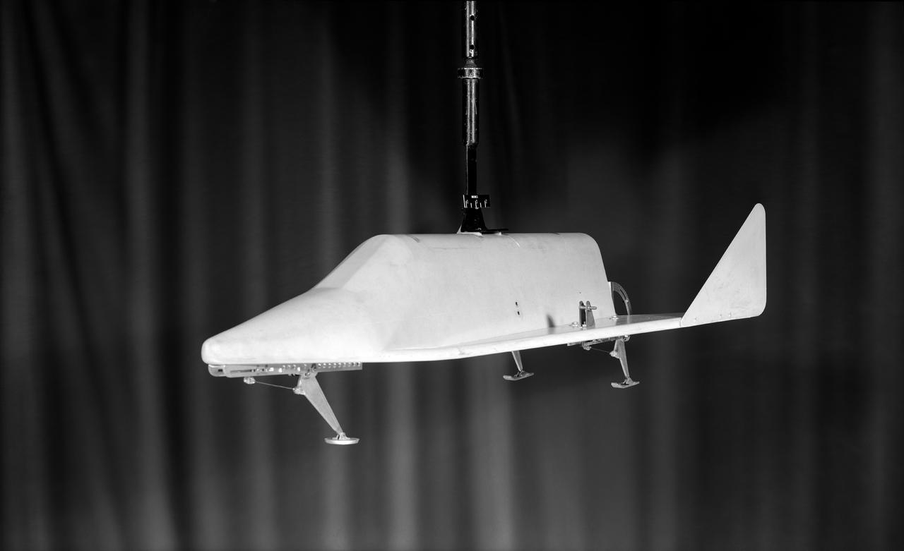
Front 3/4 view of the Avrocar mounted on variable height struts in the Ames 40x80 foot wind tunnel, without tail.
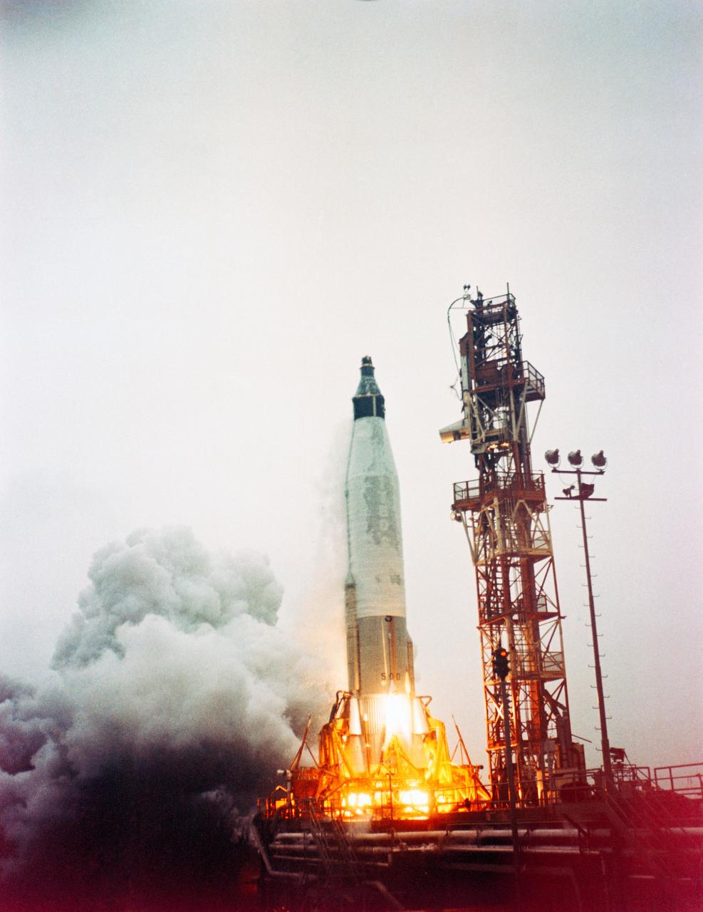
S61-01205 (29 July 1960) --- Launch of the unmanned Mercury Atlas-1 (MA-1) spacecraft for a suborbital test flight of the Mercury capsule reentry, which did not achieve orbit. The Atlas exploded 65 seconds after launch. Photo credit: NASA
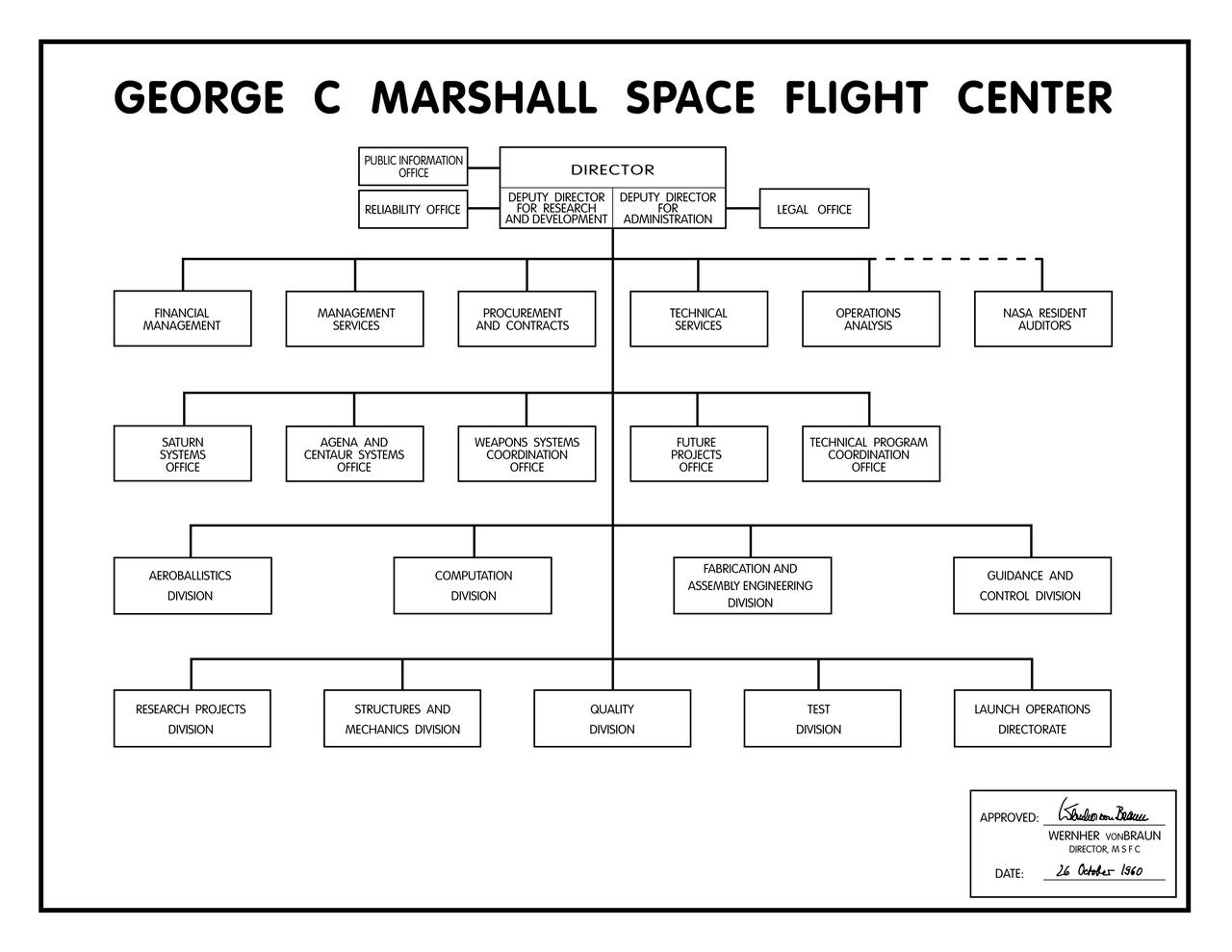
The first organizational chart of the George C. Marshall Space Flight Center (MSFC) which was approved and signed by Dr. Wernher von Braun, Director, MSFC, on 26 October 1960.
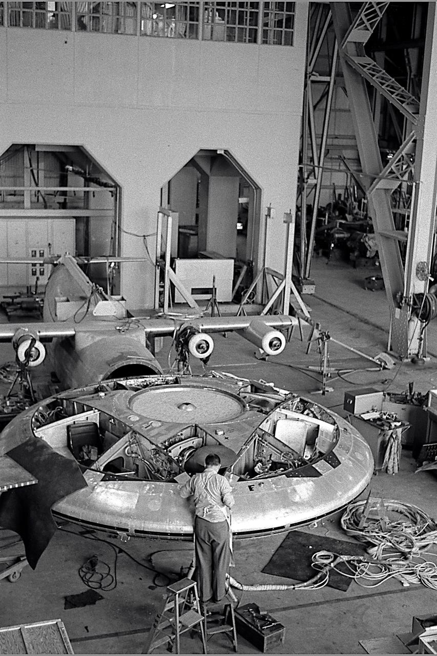
Avrocar in the shop of the 40x80 foot wind tunnel with the 4 prop tilt wing model in the back ground.
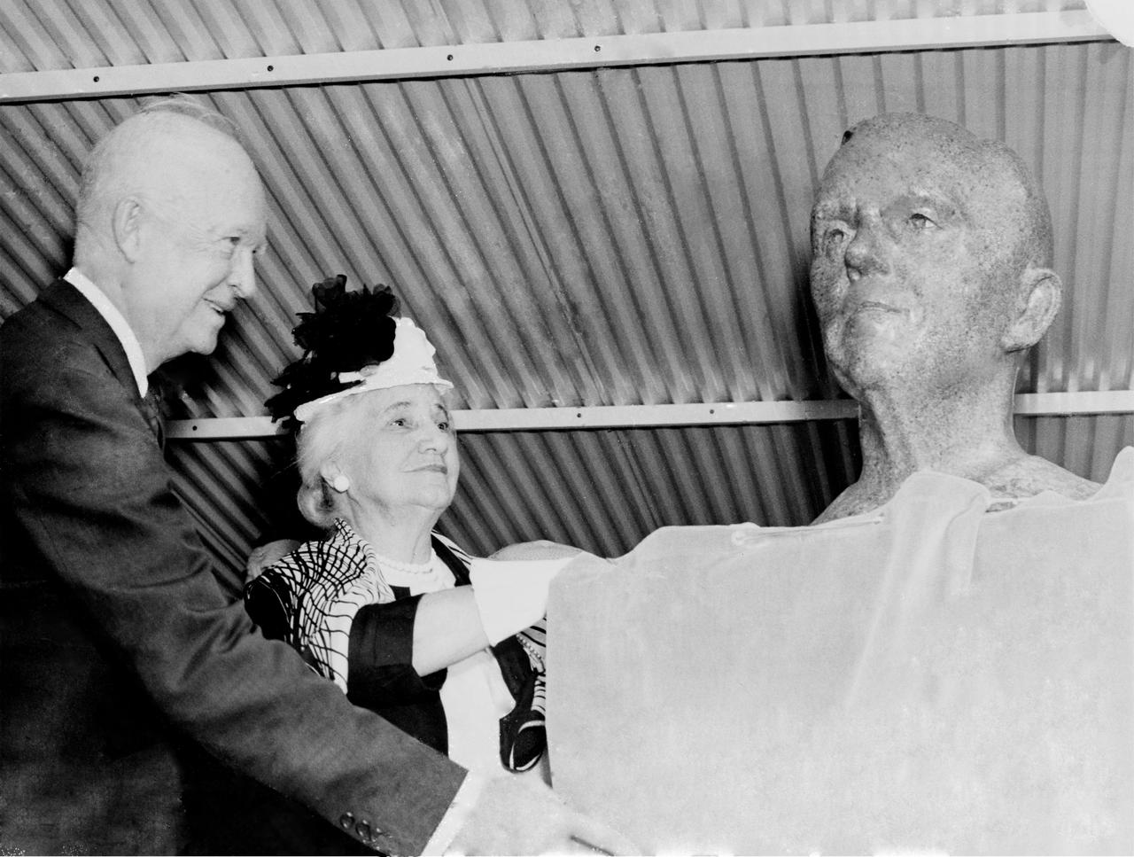
President Dwight D. Eisenhower and Mrs. George C. Marshall unveil the bronze bust of General George C. Marshall during the dedication of the Marshall Space Flight Center. Eisenhower signed an Executive Order on October 21, 1959 directing the transfer of persornel from the Redstone Arsenal's Army Ballistic Missile Agency Development Operations Division to NASA. On March 15, 1960, another Executive Order announced that the space complex formed within the boundaries of Redstone Arsenal would become the George C. Marshall Space Flight Center. The Center was activated on July 1, 1960, with dedication ceremonies taking place September 8, 1960.
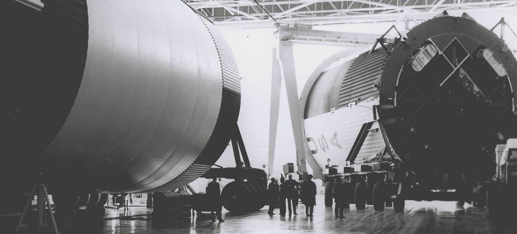
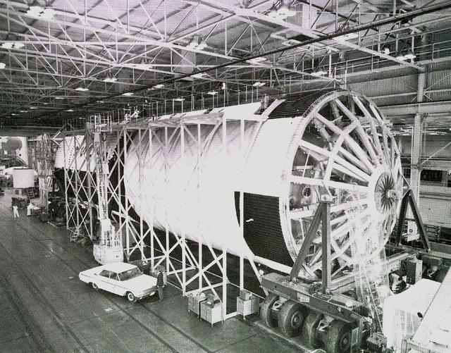
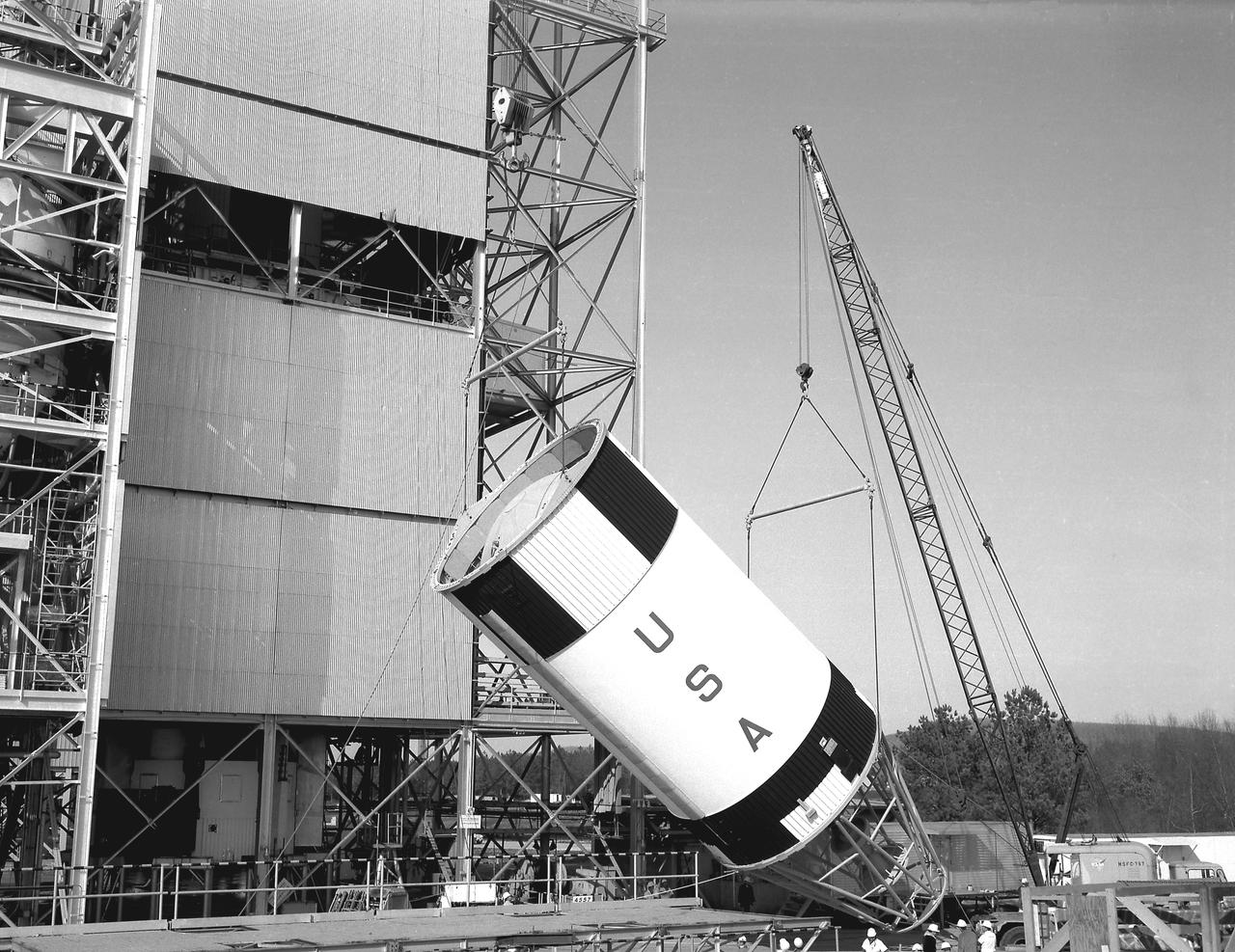
This photograph shows the Saturn V assembled LOX (Liquid Oxygen) and fuel tanks ready for transport from the Manufacturing Engineering Laboratory at Marshall Space Flight Center in Huntsville, Alabama. The tanks were then shipped to the launch site at Kennedy Space Center for a flight. The towering 363-foot Saturn V was a multi-stage, multi-engine launch vehicle standing taller than the Statue of Liberty. Altogether, the Saturn V engines produced as much power as 85 Hoover Dams.
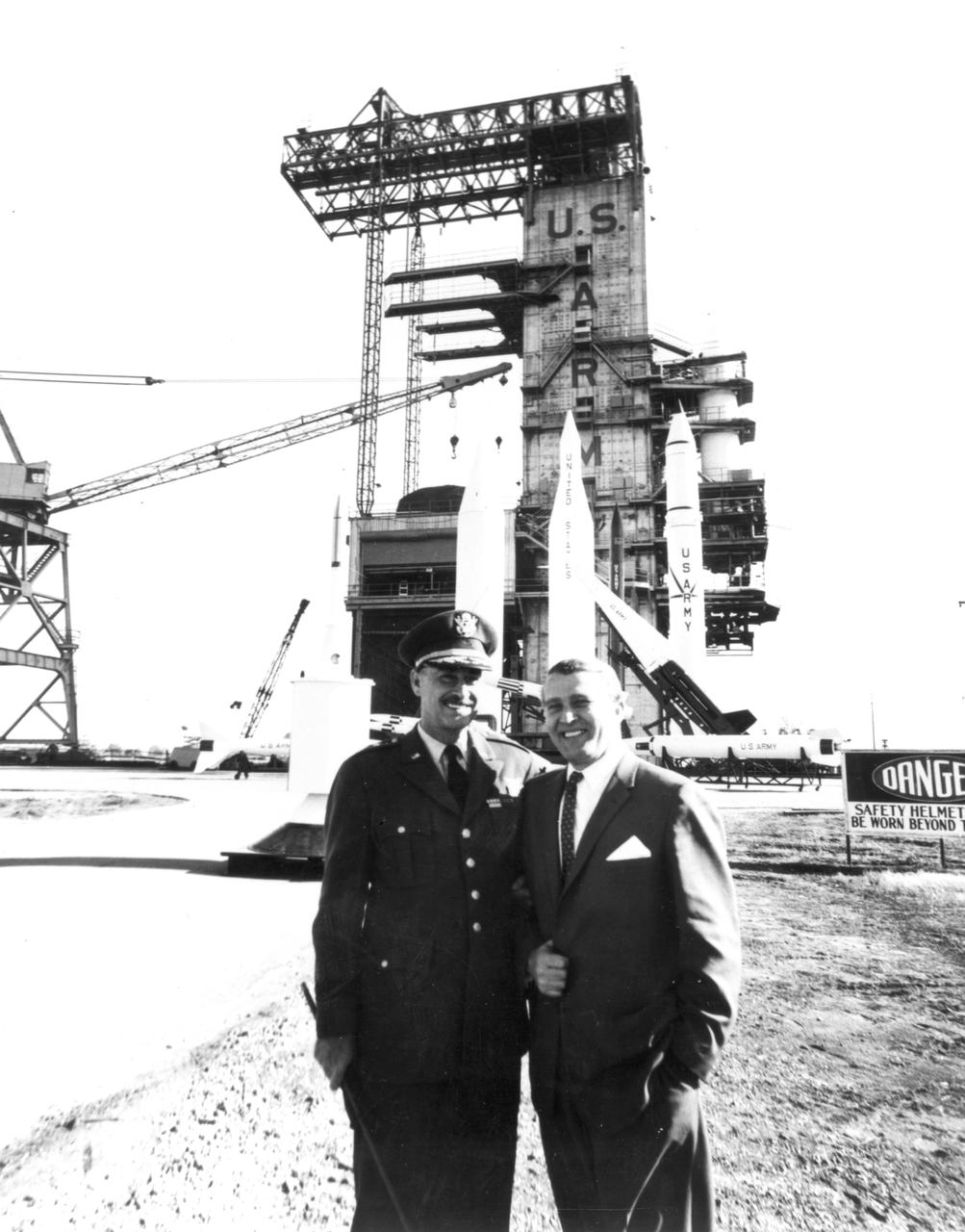
Marshall Space Flight Center’s (MSFC) Director, Dr. Wernher von Braun, is pictured here with Army Ballistic Missile Agency’s (ABMA) Commanding General, J.B. Medaris, before a display of Army missles at the ABMA test lab.
Canard model
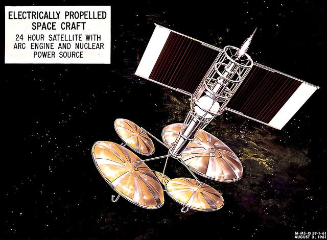
This 1960 artist's concept shows a 24-hour communication satellite design incorporating an arc engine with a nuclear power source. The concept was one of many missions proposed by the Marshall Space Flight Center for electrically-propelled spacecraft.
Images take for NASA Document L-1220
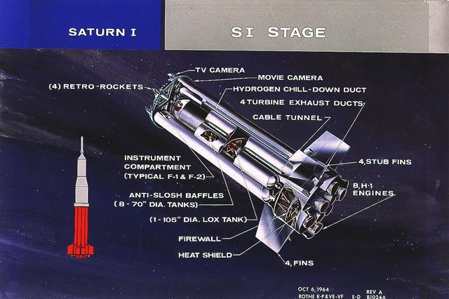
This cutaway illustrates the S-I stage, the first stage of the Saturn I vehicle developed by the Marshall Space Flight Center (MSFC). The stage was propelled by a cluster of eight H-1 engines, capable of producing 1,500,000 pounds of thrust.
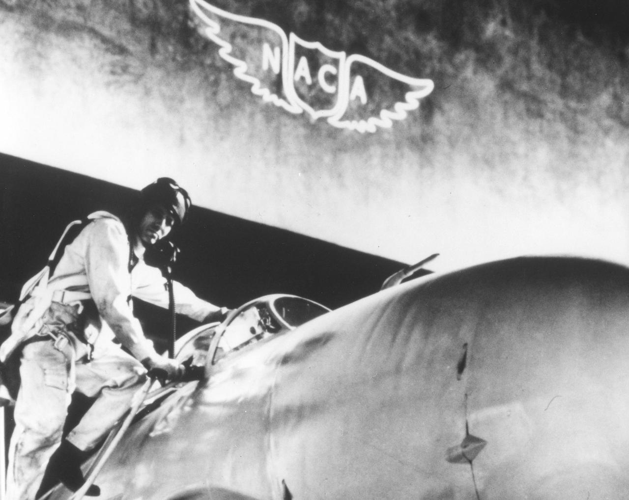
The Marshall Space Flight Center was activated on July 1, 1960 as a part of NASA, which had been established on October 1, 1958 by Congressional passage of the National Aeronautics and Space Act. The nucleus of NASA was the Advisory Committee for Aeronautics later named the National Advisory Committee for Aeronauts (NACA). The NACA was founded in 1915 to study the problems of flight and to recommend practical solutions to basic aircraft design and construction problems. NACA's wind turnels and other research facilities made NACA technical reports the basis for aviation progress for more than 40 years.
The Little Joe launch vehicle being readied for a test launch from Wallops in January 1960... Page 77. Photograph published in Winds of Change, 75th Anniversary NASA publication, by James Schultz. **note - see L59-5137 page 77 also. Photograph published in Engineer in Charge: A History of the Langley Aeronautical Laboratory, 1917-1958 by James R. Hansen. Page 389. ...was conceived by Langley engineers Max Faget and Paul Purser even before STG (Space Task Group) was organized.
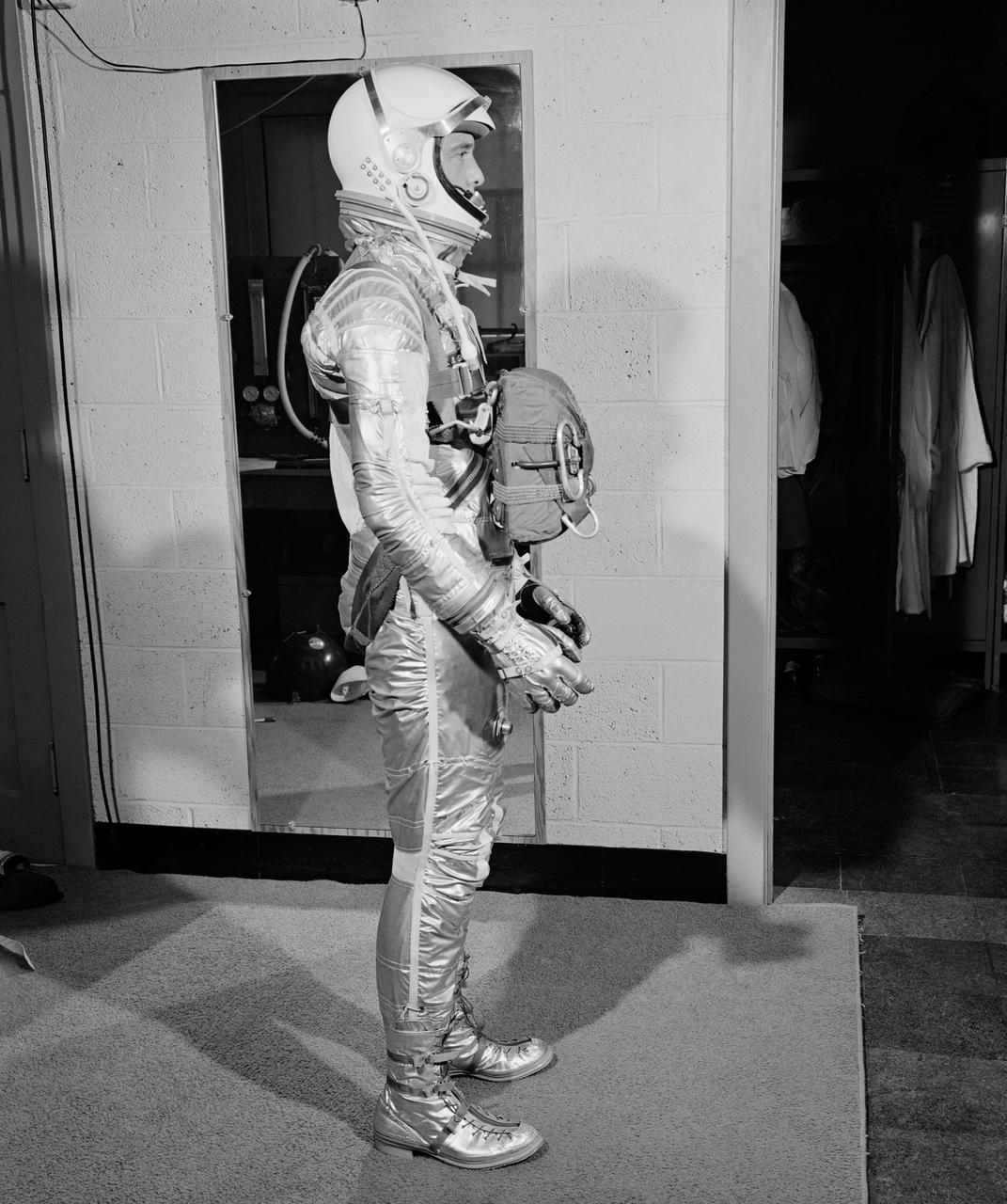
G60-02665 (1960) --- Astronaut Alan B. Shepard Jr., Mercury-Redstone 3 (MR-3) pilot, wearing pressure suit with body parachute. Photo credit: NASA or National Aeronautics and Space Administration
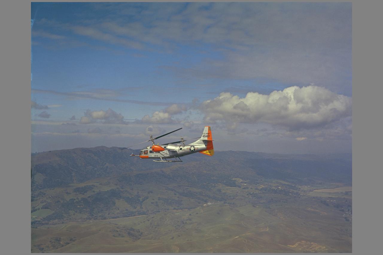
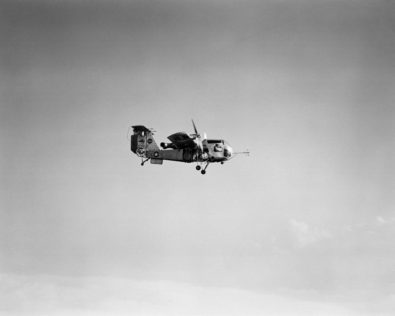
BELL XV-3 (AF54-148) Convertiplane (experimental tilt rotor) IN FLIGHT Note: Used in publication in Flight Research at Ames; 57 Years of Development and Validation of Aeronautical Technology NASA SP-1998-3300 fig. 121
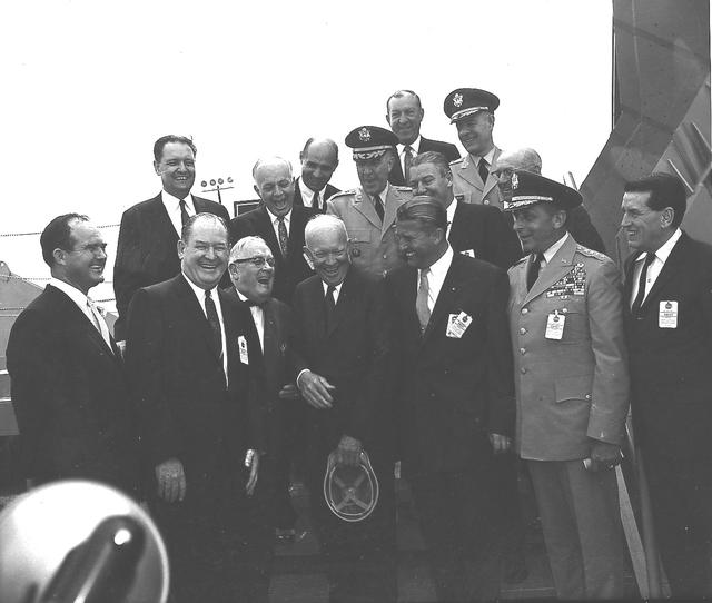
President Dwight D. Eisenhower and MSFC Director Dr. Wernher von Braun share a joke as other dignitaries look on. Eisenhower was visiting Marshall to participate in the September 8, 1960 dedication ceremony.
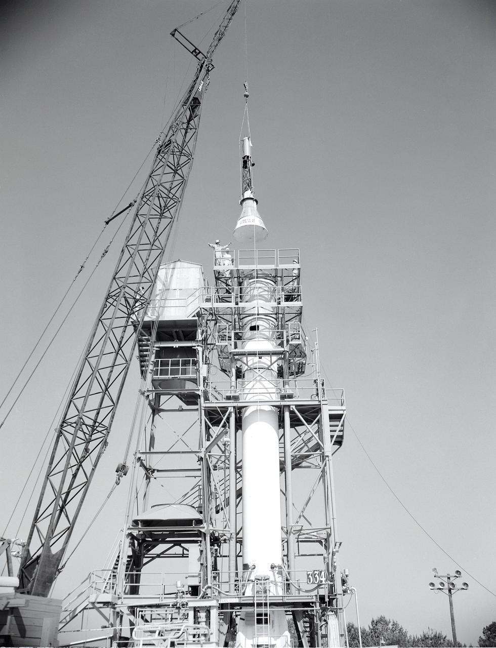
Installation of the Mercury capsule on Redstone booster at the Redstone Test Stand. Assembled at the Marshall Space Flight Center (MSFC), the Mercury-Redstone launch vehicle was designed to place a marned space capsule into orbital flight around the Earth and recover both safely.
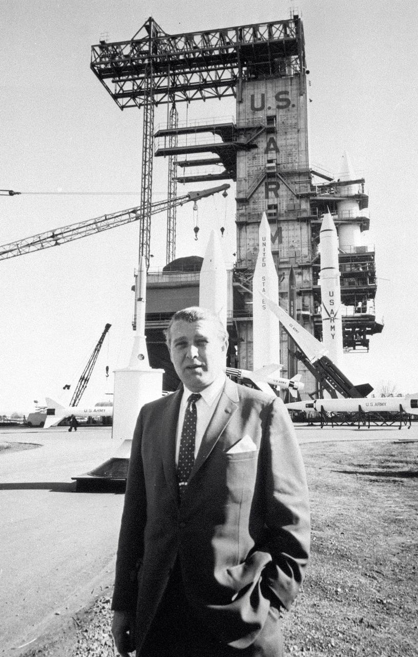
In this photo, Director of the US Army Ballistic Missile Agency (ABMA) Development Operations Division, Dr. Wernher von Braun, is standing before a display of Army missiles celebrating ABMA's Fourth Open House. The missiles in the background include (left to right) a satellite on a Juno II shroud with a Nike Ajax pointing left in front of a Jupiter missile. The Lacrosse is in front of the Juno II. The Nike Hercules points skyward in front of the Juno II and the Redstone.
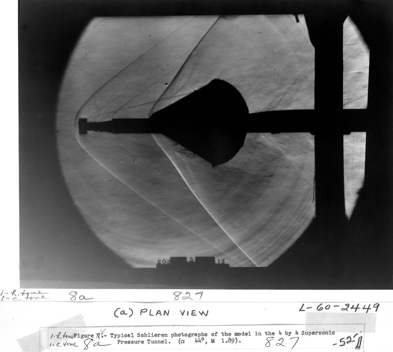
Schlieren photographs of the model in 4 x 4 Foot supersonic pressure tunnel
RVD Model #176
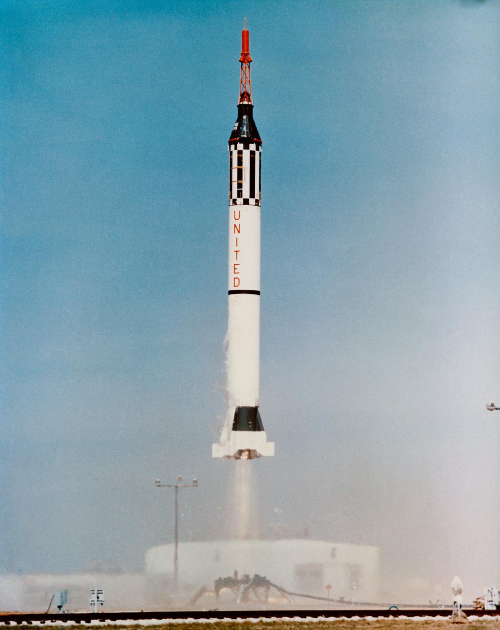
S62-08106 (19 Dec. 1960) --- Launch of the unmanned Mercury Redstone 1A (MR-1A) from Cape Canaveral on Dec. 19, 1960. Successful flight to peak altitude of 135 statue miles. Horizontal distance of 235 statue miles. Photo credit: NASA
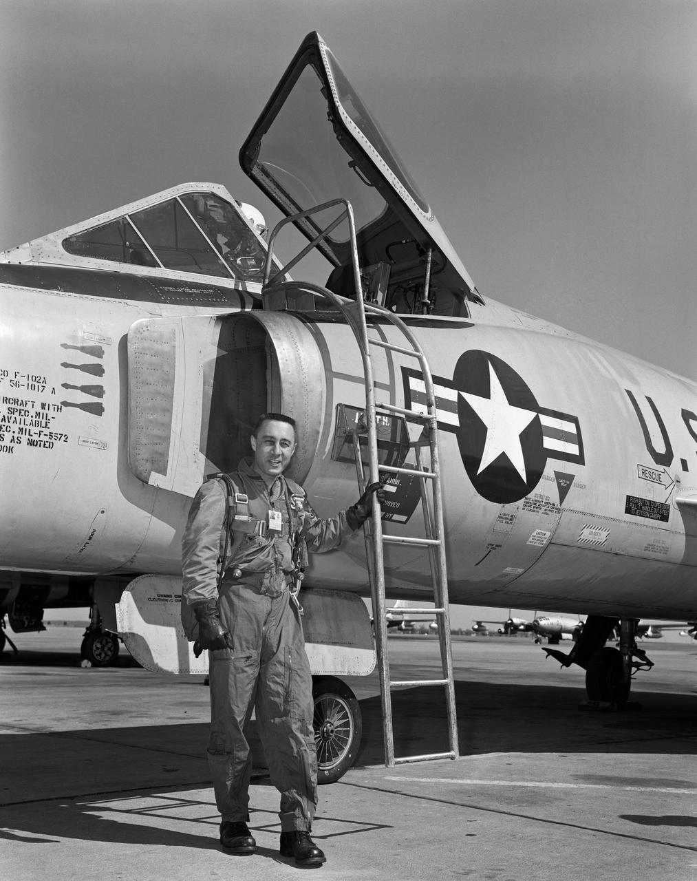
B60-00708 (1960) --- Astronaut Virgil I (Gus) Grissom pictured standing beside a F-102 on the flight line. Photo credit: NASA
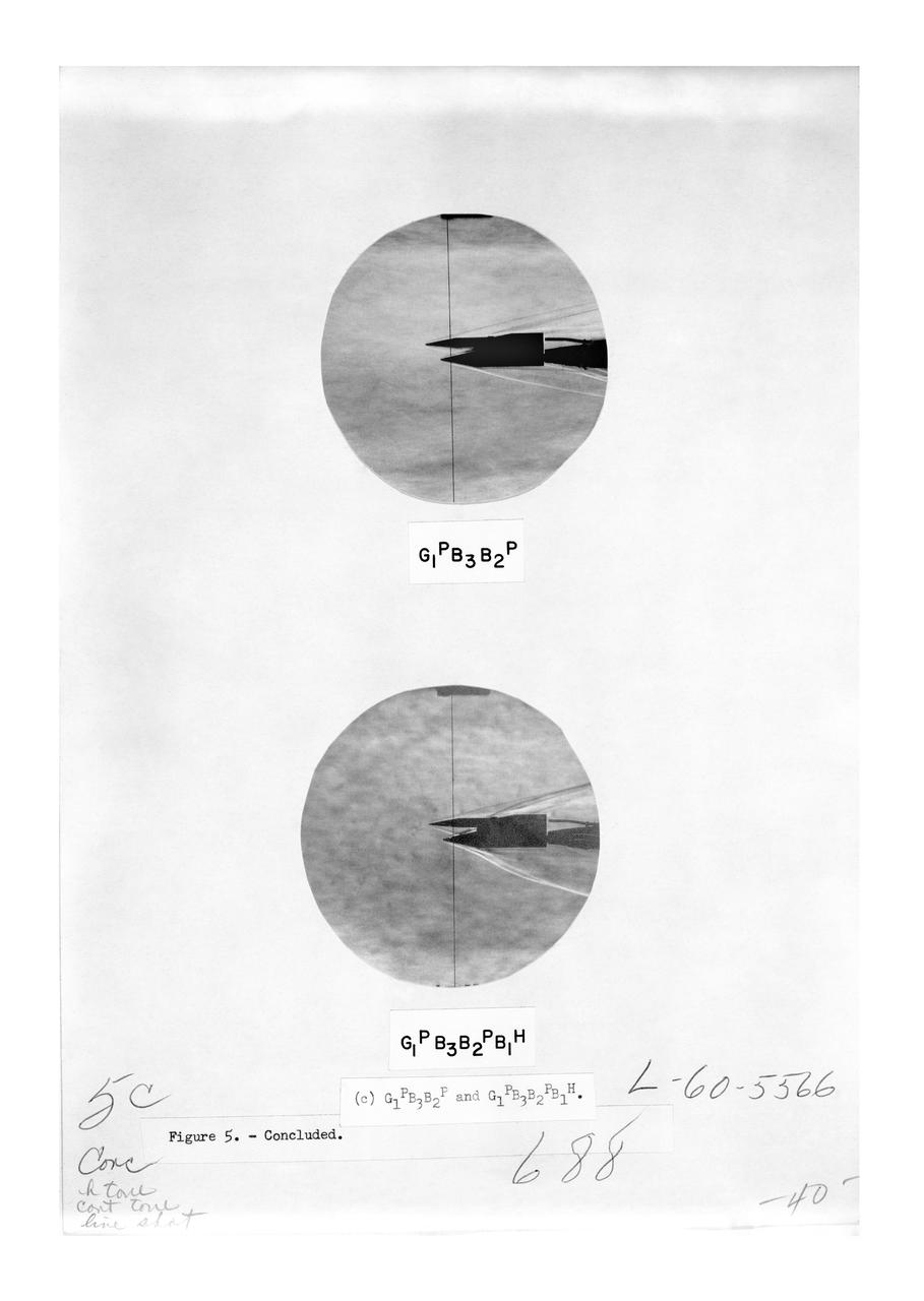
Figure 3-5 for NASA Document TM-X-356
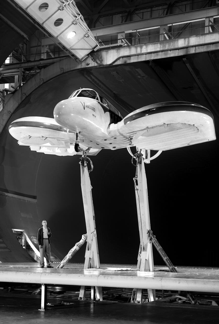
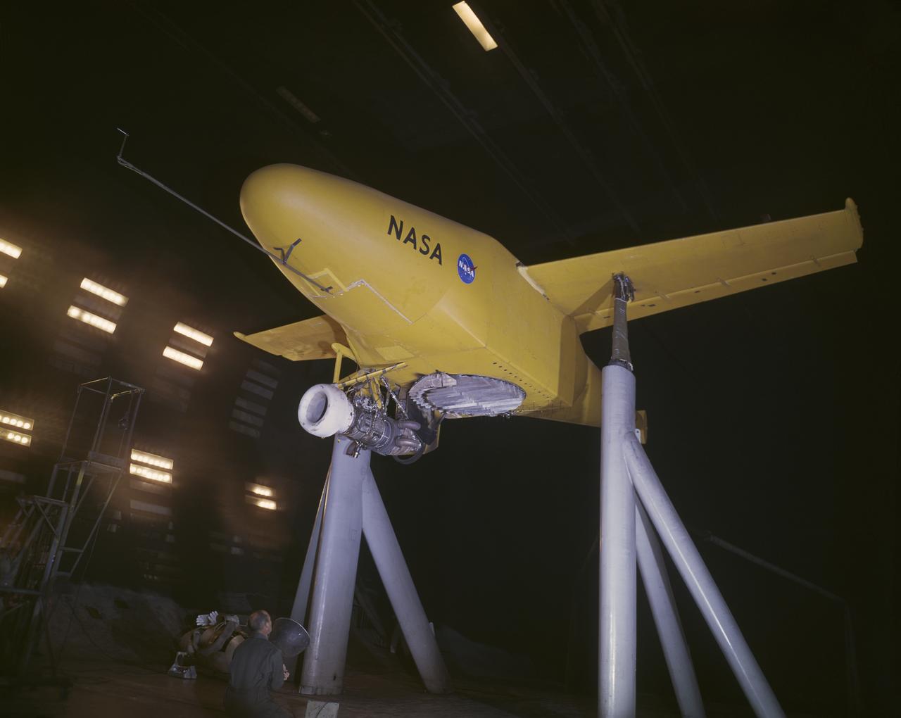
Vanguard 2C vertical take-off and landing (VTOL) airplane, wind tunnel test. Front view from below, model 14 1/2 feet high disk off. Nasa Ames engineer Ralph Maki in photo. Variable height struts and ground plane, low pressure ratio, fan in wing. 02/01/1960.
Adolf Busemann, the German aerodynamicist who first expressed the advantages of wing sweep in a 1935 theoretical paper, came to work at Langley in May 1947 as a result of Operation Paperclip. Photograph published in Engineer in Charge: A History of the Langley Aeronautical Laboratory, 1917-1958 by James R. Hansen. Page 283.
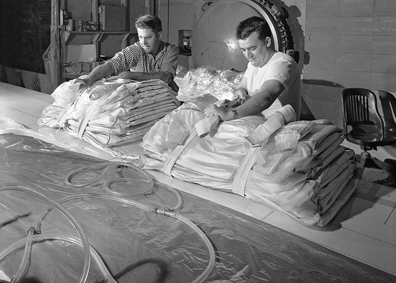
100' Satellite Packaging of Echo
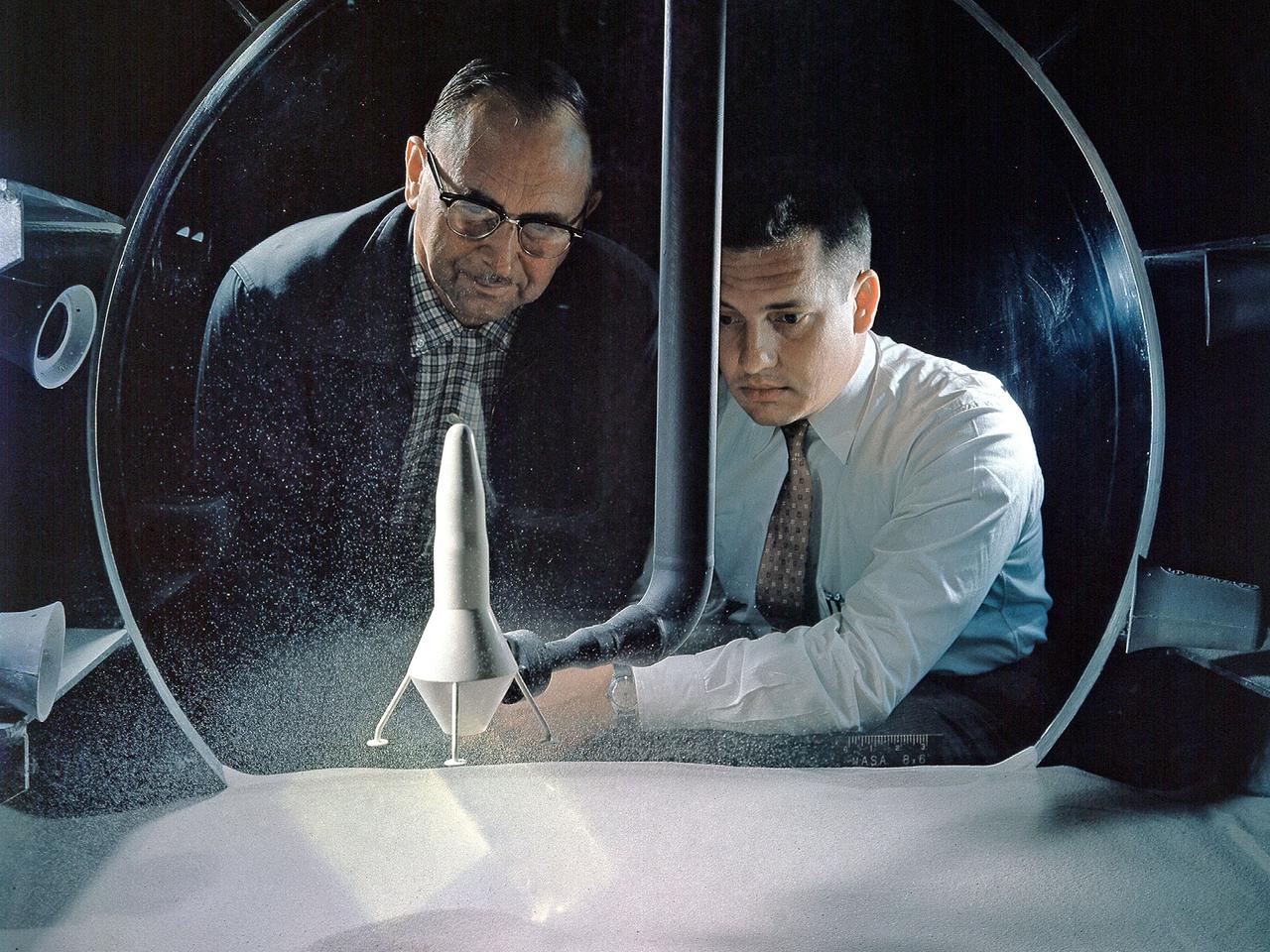
NASA Researchers view a demonstration of the moon dust simulator in the 8- by 6-Foot Supersonic Wind Tunnel facility at the National Aeronautics and Space Administration (NASA) Lewis Research Center. The researchers were studying the effect of the lunar lander’s retrorockets on the loose dust on the lunar surface. There was some concern that the retrorockets would kick up so much dust that the crew would lose the ability to see. They also did not know how the dust’s behavior would be affected by the space atmosphere. This small vacuum tank was built for very preliminary investigations into this matter. The pipe entering the top of the tank supplied the airflow to the lander model, which was affixed to the pipe. The researchers altered the vacuum levels and speed of the airflow.
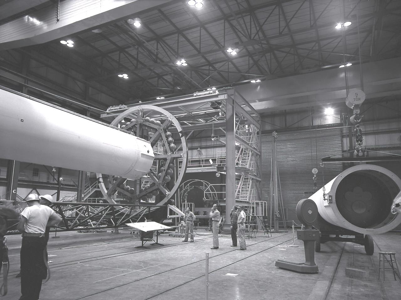
The Saturn I liquid-oxygen (LOX) tank for the Saturn I S-I stage being aligned with the end spider beam in the fabrication and engineering laboratory, building 4705, at the Marshall Space Flight Center (MSFC).
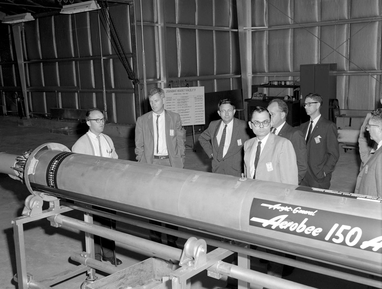
Photographed on 09/22/1960. -- An examination of the Aerojet-General "Aerobee 150A" propulsion system in February 1960. James Hansen described this as follows: "As for the technical definition of the rocket...the Langley engineers tried to keep developmental costs and time to a minimum by selecting components from off-the-shelf hardware. the majority of Scout's components were to come from an inventory of solid-fuel rockets produced for the military, although everyone involved understood that some improved motors would also have to be developed under contract. By early 1959, after intensive technical analysis and reviews, Langley settled on a design and finalized the selection of the major contractors. The rocket's 40-inch-diameter first stage was to be a new "Algol" motor, a combination of the Jupiter Senior and the navy Polaris produced by the Aerojet General Corporation, Sacramento, California. The 31-inch-diameter second stage, "Castor," was derived from the army's Sergeant and was to be manufactured by the Redstone Division of the Thiokol company in Huntsville, Alabama. the motor for the 30-inch-diameter third stage, "Antares," evolved under NASA contract from the ABL X248 design into a new version called the X254 (and subsequently into the X259); it was built under contract to NASA by ABL, a U.S. Navy Bureau of Ordnance facility operated by the Hercules Powder Company, Cumberland, Maryland. the final upper-stage propulsion unit, "Altair," which was 25.7 inches in diameter (34 inches at the heat shield), amounted to an improved edition of the X248 that was also manufactured by ABL." -- Published in James R. Hansen, Spaceflight Revolution: NASA Langley Research Center From Sputnik to Apollo, NASA SP-4308, pp.200-201.
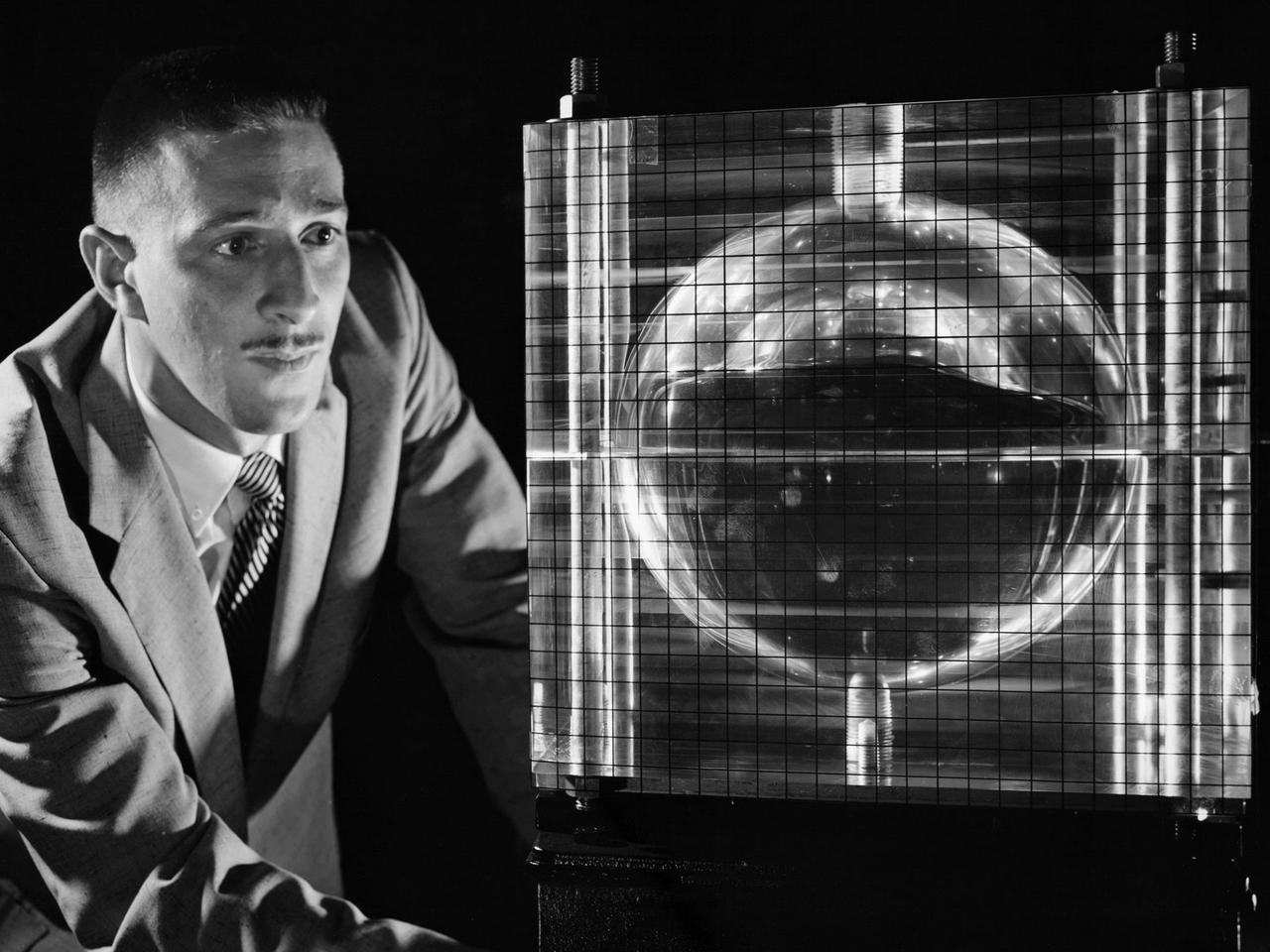
Andy Stofan views a small-scale tank built to study the sloshing characteristics of liquid hydrogen at the National Aeronautics and Space Administration (NASA) Lewis Research Center. Stofan was tasked with the study of propellant motion, or sloshing, in space vehicle propellant tanks. At the time, there was little knowledge of the behavior of fluids in microgravity or the effects of the launch on the propellant’s motion. Sloshing in the tank could alter a spacecraft’s trajectory or move the propellant away from the turbopump. Stofan became an expert and authored numerous technical reports on the subject. Stofan was assigned to the original Centaur Project Office in 1962 as a member of the Propellant Systems Section. Stofan was instrumental in solving a dynamic instability problem on the Centaur vehicle and served as the systems engineer for the development of the Centaur propellant utilization system. The solution was also applied to the upper-stages of Saturn. In 1966, Stofan was named Head of the Propellant Systems Section. Stofan continued rising through the managerial ranks at Lewis. In 1967 he became Project Manager of a test program that successfully demonstrated the use of a pressurization system for the Centaur vehicle; in 1969 the Assistant Project Manager on the Improved Centaur project; in 1970 Manager of the Titan/Centaur Project Office; in 1974 Director of the Launch Vehicles Division. In 1978, Stofan was appointed Deputy Associate Administrator for the Headquarters Office of Space Science. In 1982, he was named Director of Lewis Research Center.
Pilots With The Vertol VZ-2 (Model 76)
L60-5232 Clinton E. Brown of the Brown Hypersonic Study Group. Photograph published in Engineer in Charge: A History of the Langley Aeronautical Laboratory, 1917-1958 by James R. Hansen. Page 352.
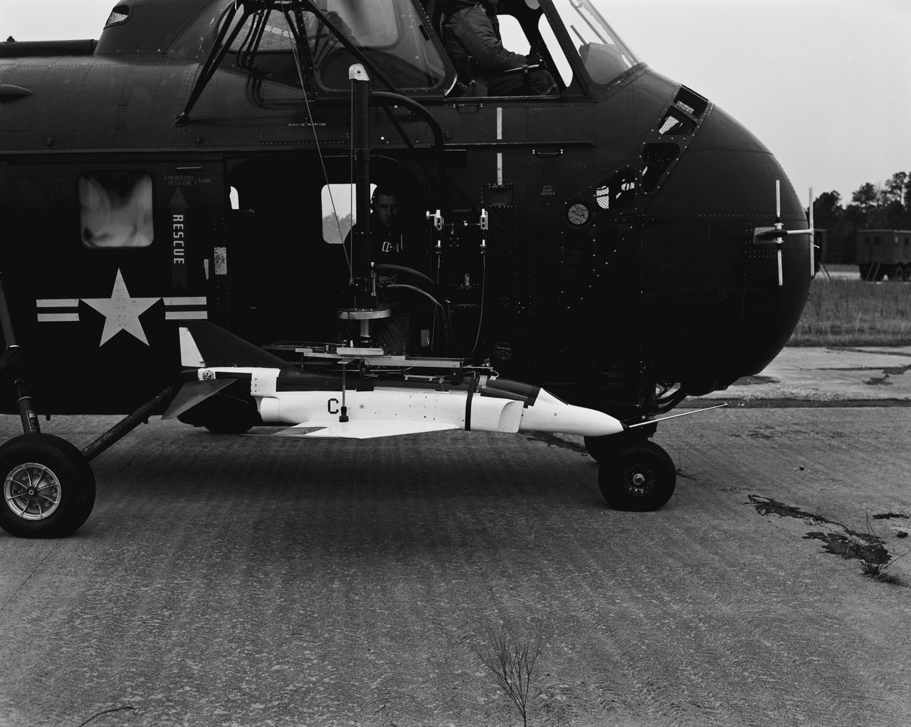
Model being tested with helicopter.
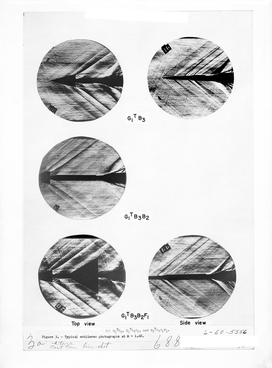
Figure 3-5 for NASA Document TM-X-356
This photograph was taken in 1960 and shows Dr. von Braun, left, and Secretary of the Army, Wilbur Brucker in the Army Ballistic Missile Agency (ABMA) Fabrication Laboratory.
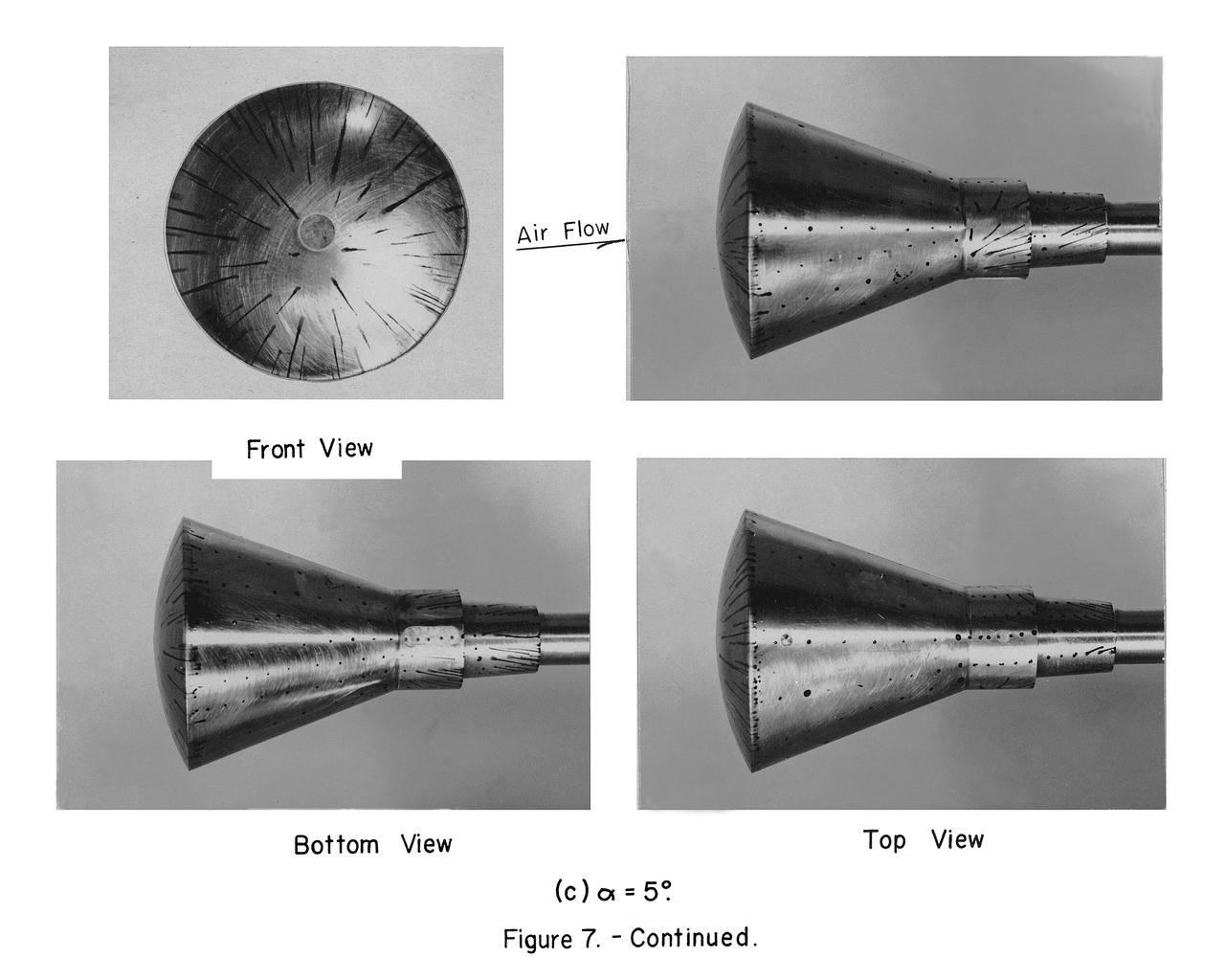
Photos of the eleven booster configurations
G60-02741 (May 1960) --- Astronaut Walter M. Schirra Jr. Photo credit: NASA
This chart provides the vital statistics for the F-1 rocket engine. Developed by Rocketdyne, under the direction of the Marshall Space Flight Center, the F-1 engine was utilized in a cluster of five engines to propel the Saturn V's first stage, the S-IC. Liquid oxygen and kerosene were used as its propellant. Initially rated at 1,500,000 pounds of thrust, the engine was later uprated to 1,522,000 pounds of thrust after the third Saturn V launch (Apollo 8, the first marned Saturn V mission) in December 1968. The cluster of five F-1 engines burned over 15 tons of propellant per second, during its two and one-half minutes of operation, to take the vehicle to a height of about 36 miles and to a speed of about 6,000 miles per hour.

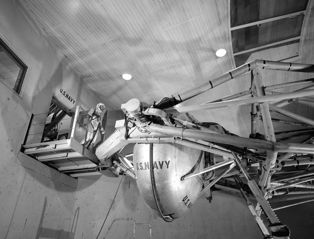
Jerrie Cobb prepares to operate the Multi-Axis Space Test Inertia Facility (MASTIF) inside the Altitude Wind Tunnel at the National Aeronautics and Space Administration (NASA) Lewis Research Center. The MASTIF was a three-axis rig with a pilot’s chair mounted in the center to train Project Mercury pilots to bring a spinning spacecraft under control. An astronaut was secured in a foam couch in the center of the rig. The rig was then spun on three axes from 2 to 50 rotations per minute. The pilots were tested on each of the three axis individually, then all three simultaneously. The two controllers in Cobb’s hands activated the small nitrogen gas thrusters that were used to bring the MASTIF under control. A makeshift spacecraft control panel was set up in front of the trainee’s face. Cobb was one of several female pilots who underwent the skill and endurance testing that paralleled that of the Project Mercury astronauts. In 1961 Jerrie Cobb was the first female to pass all three phases of the Mercury Astronaut Program. NASA rules, however, stipulated that only military test pilots could become astronauts and there were no female military test pilots. The seven Mercury astronauts had taken their turns on the MASTIF in February and March 1960.
F-104A #734 on lakebed. 11/16/60
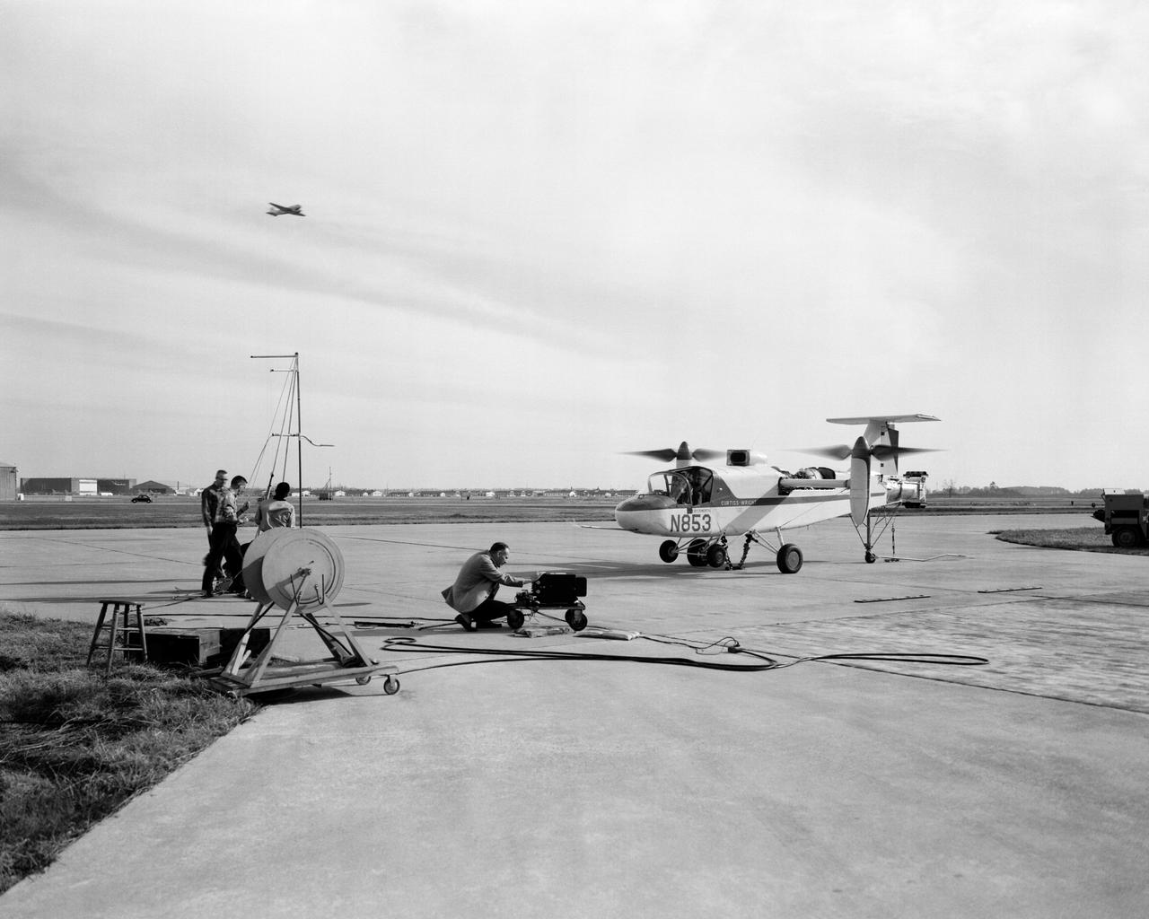
Curtiss-Wright X-100 (VTOL) Vertical Take-Off Transport.
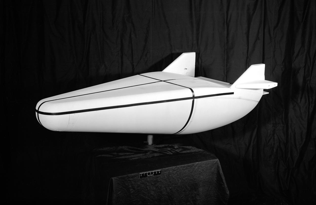
Model of Winged Space Vehicle
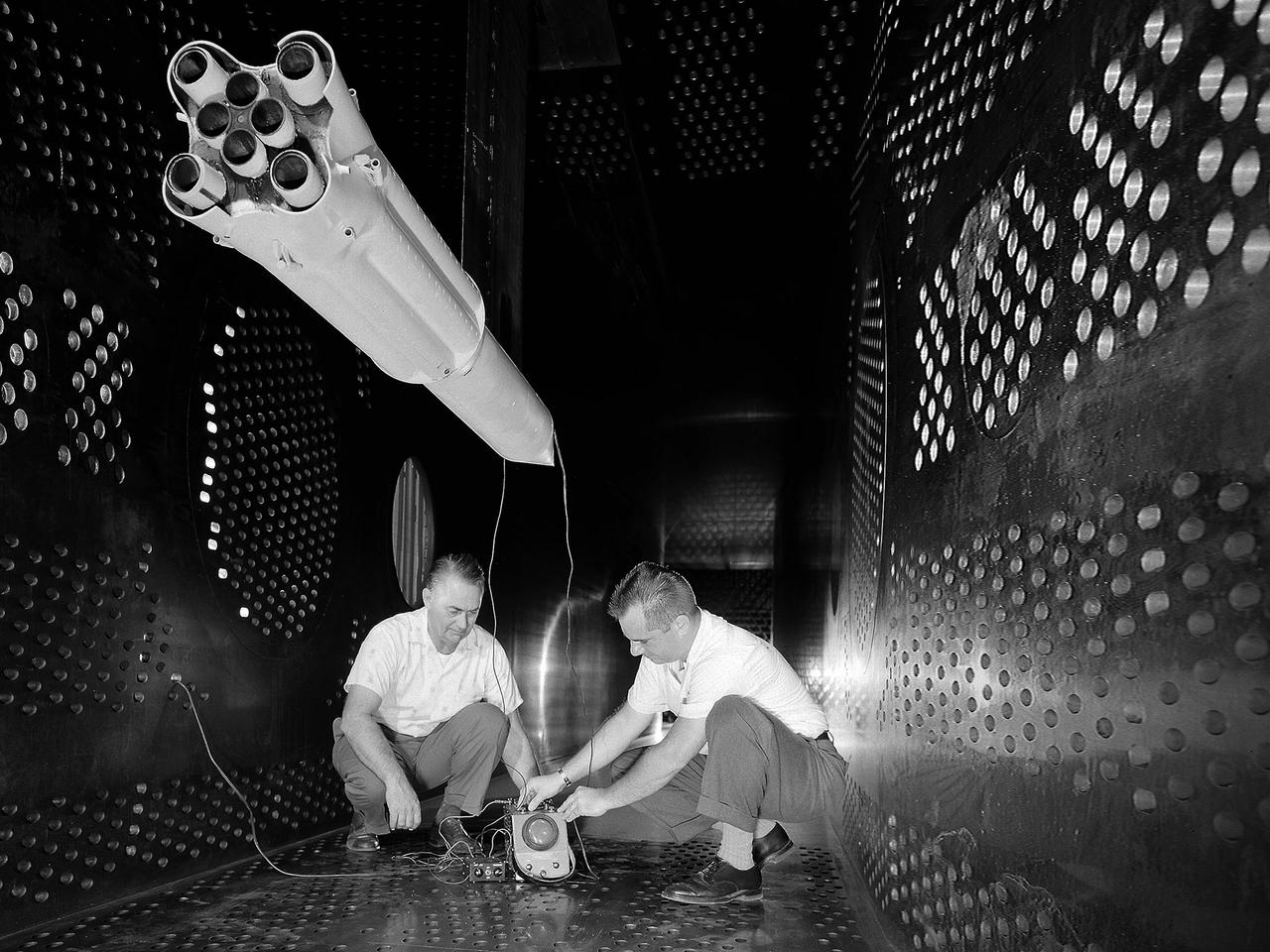
National Aeronautics and Space Administration (NASA) researchers set up instrumentation on a 0.037- scale model of a Saturn booster in the 8- by 6-Foot Supersonic Wind Tunnel at the NASA Lewis Research Center. In October 1960 Lewis researchers John Allen and Robert Wasko began a 14-month investigation of the eight-engine booster’s base heating in the tunnel. The model resembled the Saturn C-1, but only the afterbody totally mimicked the C-1. The over-heating of the lower end, or base, of the booster can cause the engines to fail or introduce aerodynamic concerns. Base heating results from the rocket engines’ exhaust heat, the recirculation of that heat into the base, and the burning of combustibles. Large boosters, like the Saturn, employed clusters of rocket engines that add to the complexity of the base heating problem. The 8- by 6-foot tunnel investigations studied the Saturn at speeds from Mach 1.0 to 2.0 using liquid oxygen and JP-4 as propellants. Researchers found that the use of cooling air scoops and external flow deflectors produced significant decreases in base heating.
This photograph shows a Saturn V first stage (S-1C). This stage was assembled at the Manufacturing Engineering Laboratory at NASA's Marshall Space Flight Center. With assistance by the Boeing Company, the manufacturer, this first stage was assembled using components made by Boeing in Wichita, Kansas and New Orleans.
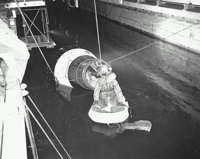
B60-00285 (1960) --- Astronaut John H. Glenn Jr., pilot of the Mercury Atlas 6 spaceflight, emerges from an egress trainer during training activity at the Langley Research Center. He is attempting to transfer onto a life raft from the mock-up of the Mercury capsule. Photo credit: NASA

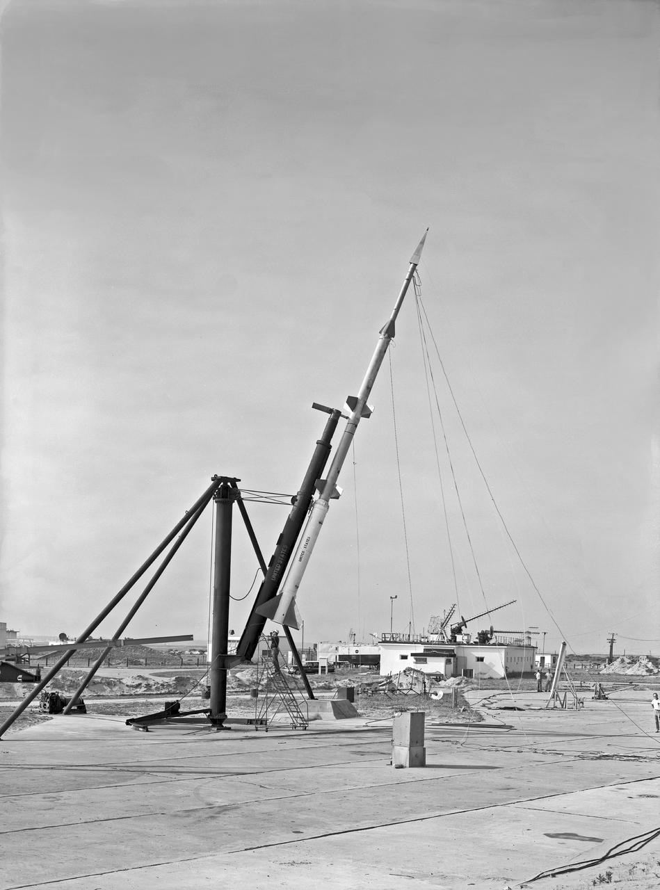
Launch Phase of ARCAS E1-239 Image taken at Wallops Island
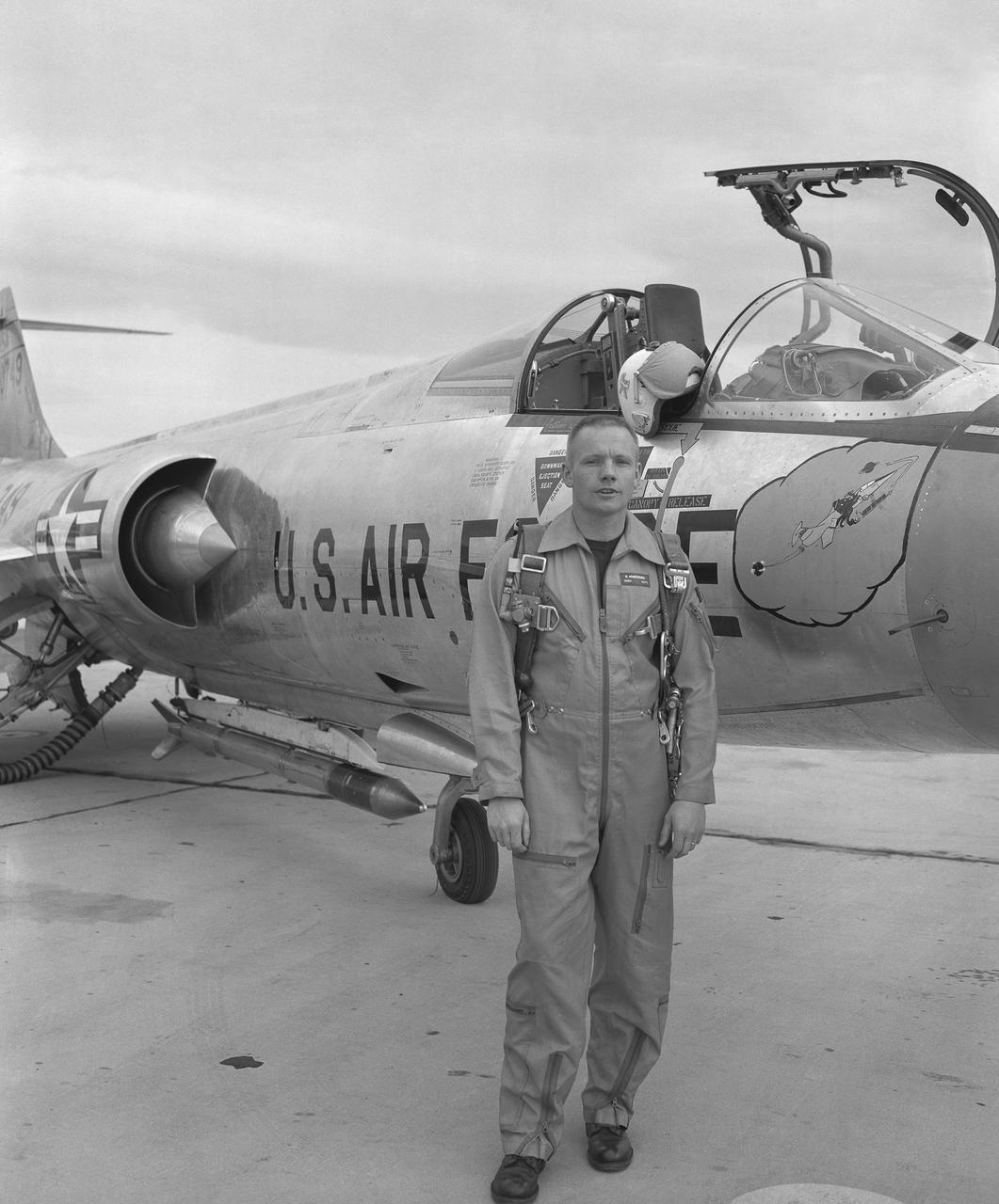
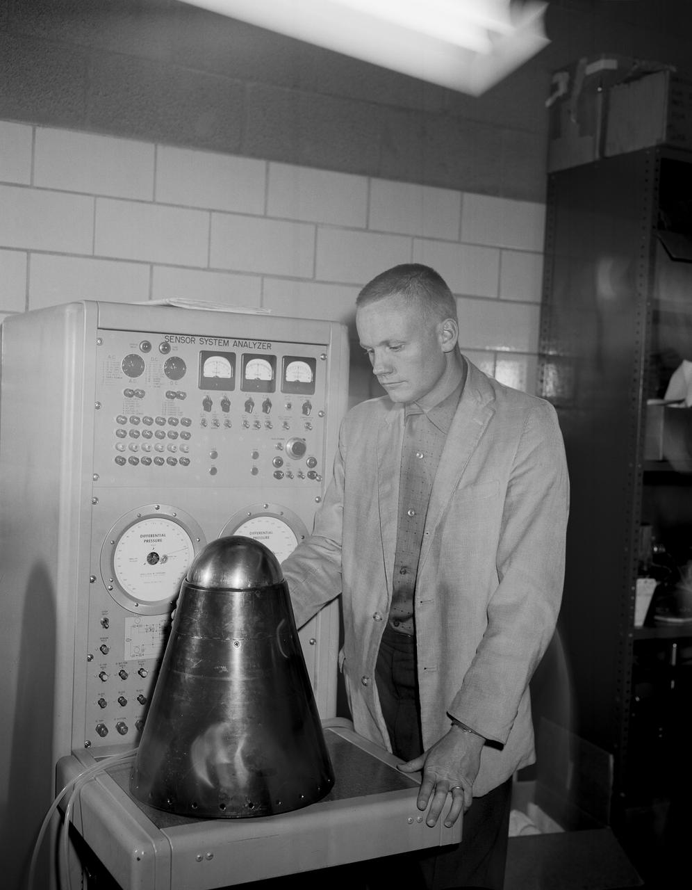
Famed astronaut Neil A. Armstrong – the first person to set foot on the Moon during the historic Apollo 11 mission in July 1969 – spent seven years as a research pilot at the NACA-NASA High-Speed Flight Station, now NASA’s Armstrong Flight Research Center in Edwards, California, before joining the space program. During his time there, he served as a project pilot on the F-100A, F-100C, F-101, and F-104A (pictured here).
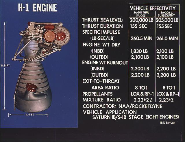
H-1 engine characteristics: The H-1 engine was developed under the management of the Marshall Space Flight Center (MSFC). The cluster of eight H-1 engines was used to power the first stage of the Saturn I (S-I stage) and Saturn IB (S-IVB stage) launch vehicles, and produced 188,00 pounds of thrust, a combined thrust of 1,500,000 pounds, later uprated to 205,000 pounds of thrust and a combined total thrust of 1,650,000 pounds for the Saturn IB program.
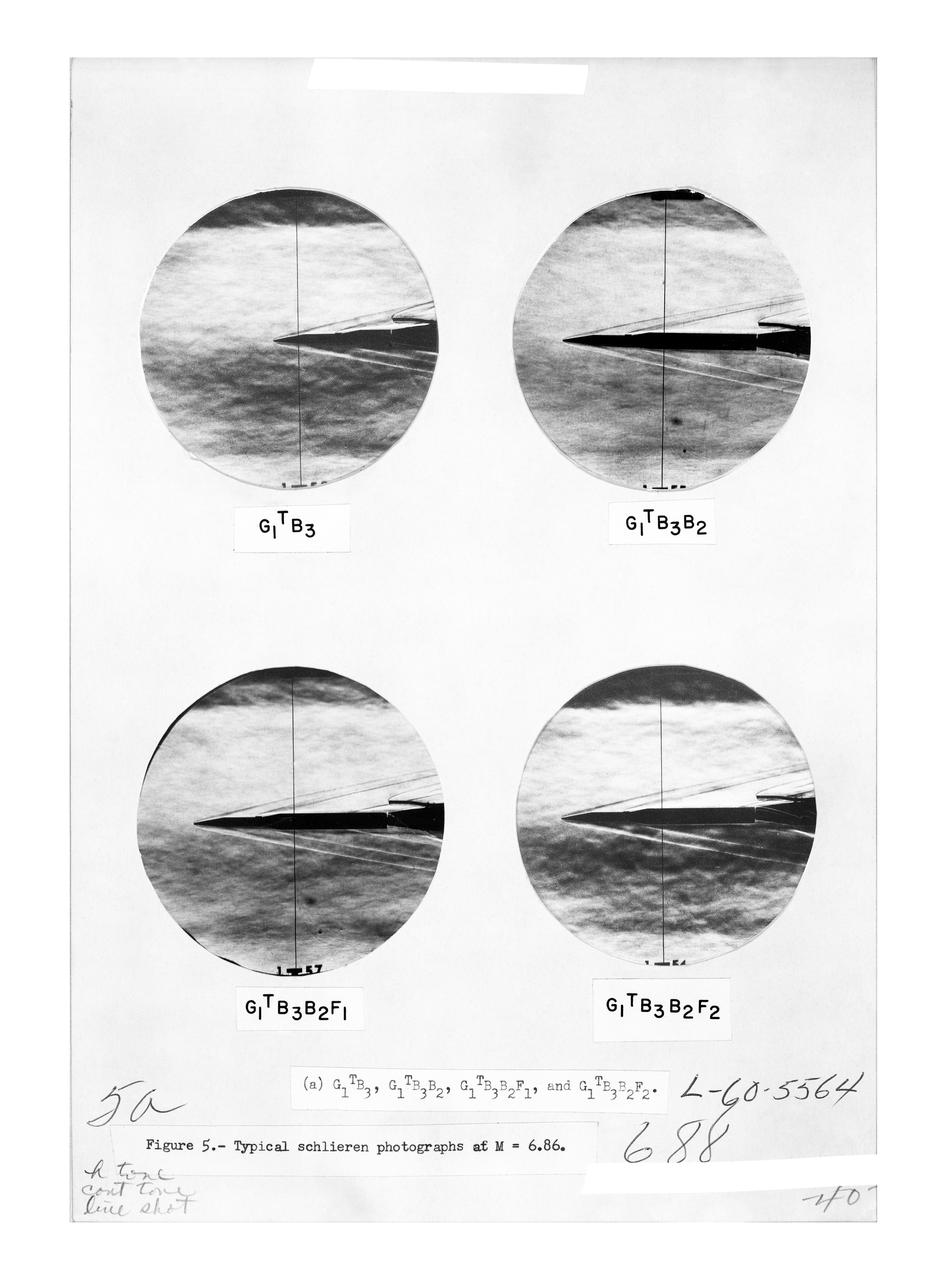
Figure 3-5 for NASA Document TM-X-356

Model of Winged Space Vehicle
The Multi-Axis Space Test Inertial Facility (MASTIF) in the Altitude Wind Tunnel at the National Aeronautics and Space Administration (NASA) Lewis Research Center. Although the Mercury astronaut training and mission planning were handled by the Space Task Group at Langley Research Center, NASA Lewis played an important role in the program, beginning with the Big Joe launch. Big Joe was a singular attempt early in the program to use a full-scale Atlas booster and simulate the reentry of a mockup Mercury capsule without actually placing it in orbit. A unique three-axis gimbal rig was built inside Lewis’ Altitude Wind Tunnel to test Big Joe’s attitude controls. The control system was vital since the capsule would burn up on reentry if it were not positioned correctly. The mission was intended to assess the performance of the Atlas booster, the reliability of the capsule’s attitude control system and beryllium heat shield, and the capsule recovery process. The September 9, 1959 launch was a success for the control system and heatshield. Only a problem with the Atlas booster kept the mission from being a perfect success. The MASTIF was modified in late 1959 to train Project Mercury pilots to bring a spinning spacecraft under control. An astronaut was secured in a foam couch in the center of the rig. The rig then spun on three axes from 2 to 50 rotations per minute. Small nitrogen gas thrusters were used by the astronauts to bring the MASTIF under control.
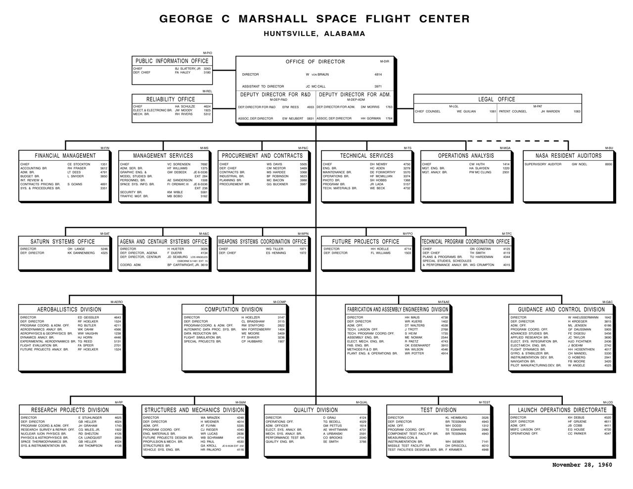
The first organizational chart for the George C. Marshall Space Flight Center (MSFC) with individual assignments, dated November 28, 1960.

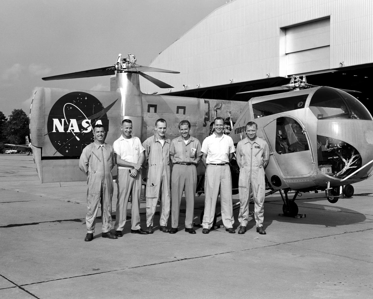
The National Aeronautics and Space Administration (NASA) Lewis Research Center acquired two North American AJ-2 Savages in the early 1960s to fly microgravity-inducing parabola flight patterns. Lewis was in the midst of an extensive study to determine the behavior of liquid hydrogen in microgravity so that proper fuel systems could be designed. Jack Enders was the primary pilot for the program and future astronaut Fred Haise worked with the cameras and instrumentation in the rear of the aircraft. North American developed the AJ-2 for the Navy in the mid-1940s as a carrier-based bomber. By the 1960s the Savage was no longer considered a modern aircraft, but its performance capabilities made it appealing to the Lewis researchers. The AJ-2 ‘s power, speed, response time, structural robustness, and large interior space were applicable to the microgravity flights. The AJ-2 could also accommodate a pilot, flight engineer, and two observers. Lewis engineers installed a 100-litre liquid hydrogen dewar, cryogenic cooling system, and cameras in the bomb bay. The AJ-2 was flown on a level course over western Lake Erie then went into a 20-degree dip to generate 375 knot. At 13,000 feet the pilot pulled the nose up by 40 degrees. The speed decreased and both latitudinal and longitudinal accelerations were nullified. Upon reaching 17,000 feet, the pilot turned the aircraft into a 45-degree dive. As the speed reached 390 knots the pilot pulled the aircraft up again. Each maneuver produced approximately 27 seconds of microgravity.
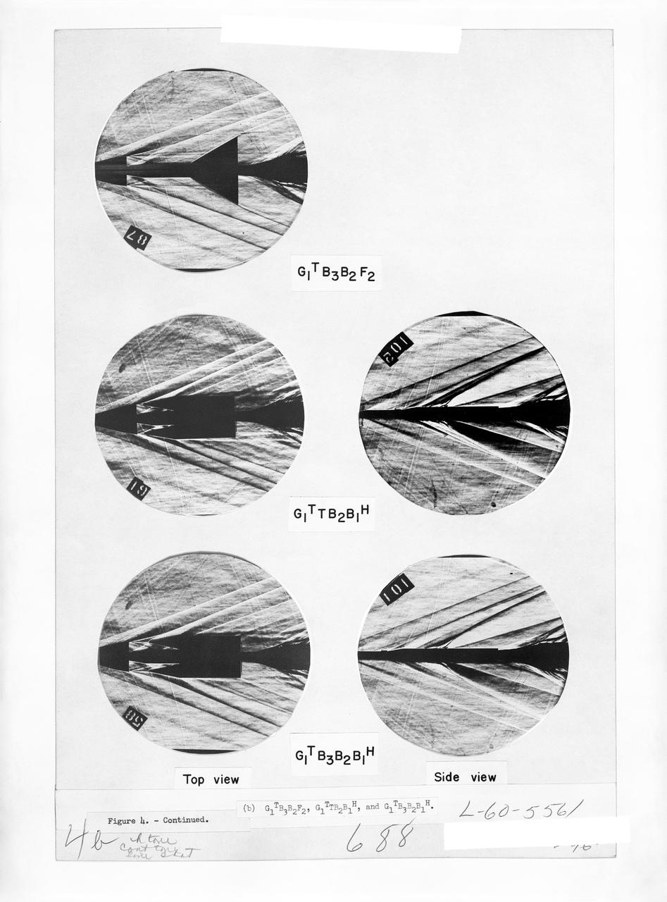
Figure 3-5 for NASA Document TM-X-356
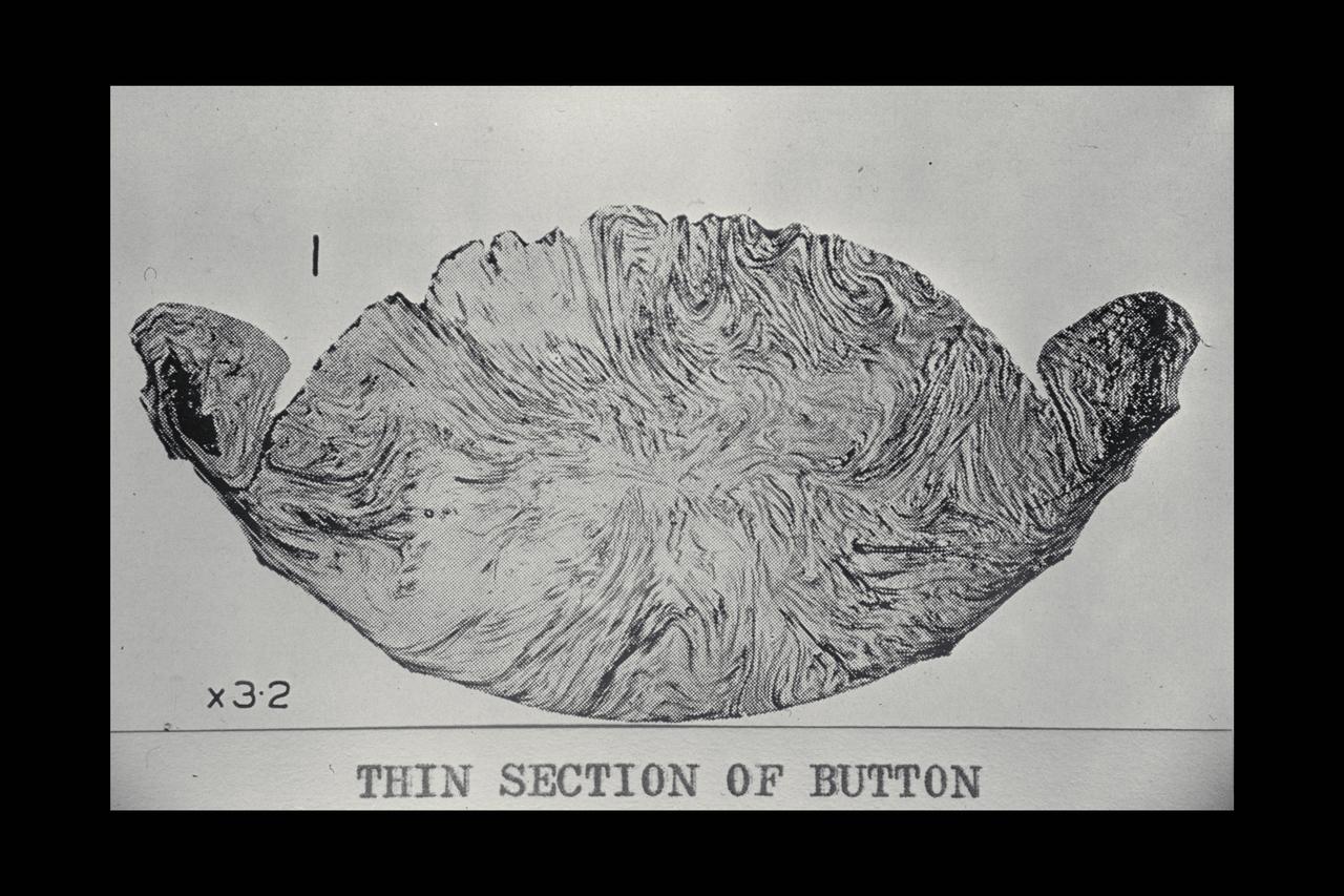
Tektites from the European collections
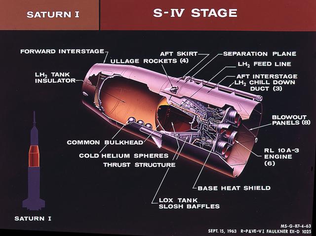
This cutaway of the Saturn I S-IV stage (second stage) illustrates the booster's components. Powered by six RL-10 engines, the S-IV stage was capable of producing 90,000 pounds of thrust. Development of the Saturn S-IV stage by the Marshall Space Flight Center (MSFC) contributed many technological breakthroughs vital to the success of the Apollo lunar program, including the use of liquid hydrogen as a propellant.
M-1 reentry body test model in high enthalpy (heat function) air stream
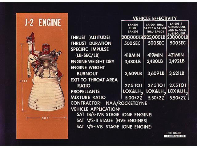
This chart is an illustration of J-2 Engine characteristics. A cluster of five J-2 engines powered the Saturn V S-II (second) stage with each engine providing a thrust of 200,000 pounds. A single J-2 engine powered the S-IVB stage, the Saturn IB second stage, and the Saturn V third stage. The engine was uprated to provide 230,000 pounds of thrust for the fourth Apollo Saturn V flight and subsequent missions. Burning liquid hydrogen as fuel and using liquid oxygen as the oxidizer, the cluster of five J-2 engines for the S-II stage burned over one ton of propellant per second, during about 6 1/2 minutes of operation, to take the vehicle to an altitude of about 108 miles and a speed of near orbital velocity, about 17,400 miles per hour.
This photograph is believed to have been taken in the early 1960s and shows Dr. von Braun at the Douglas Aircraft Company's Missile Space Systems Division in Sacramento, California.
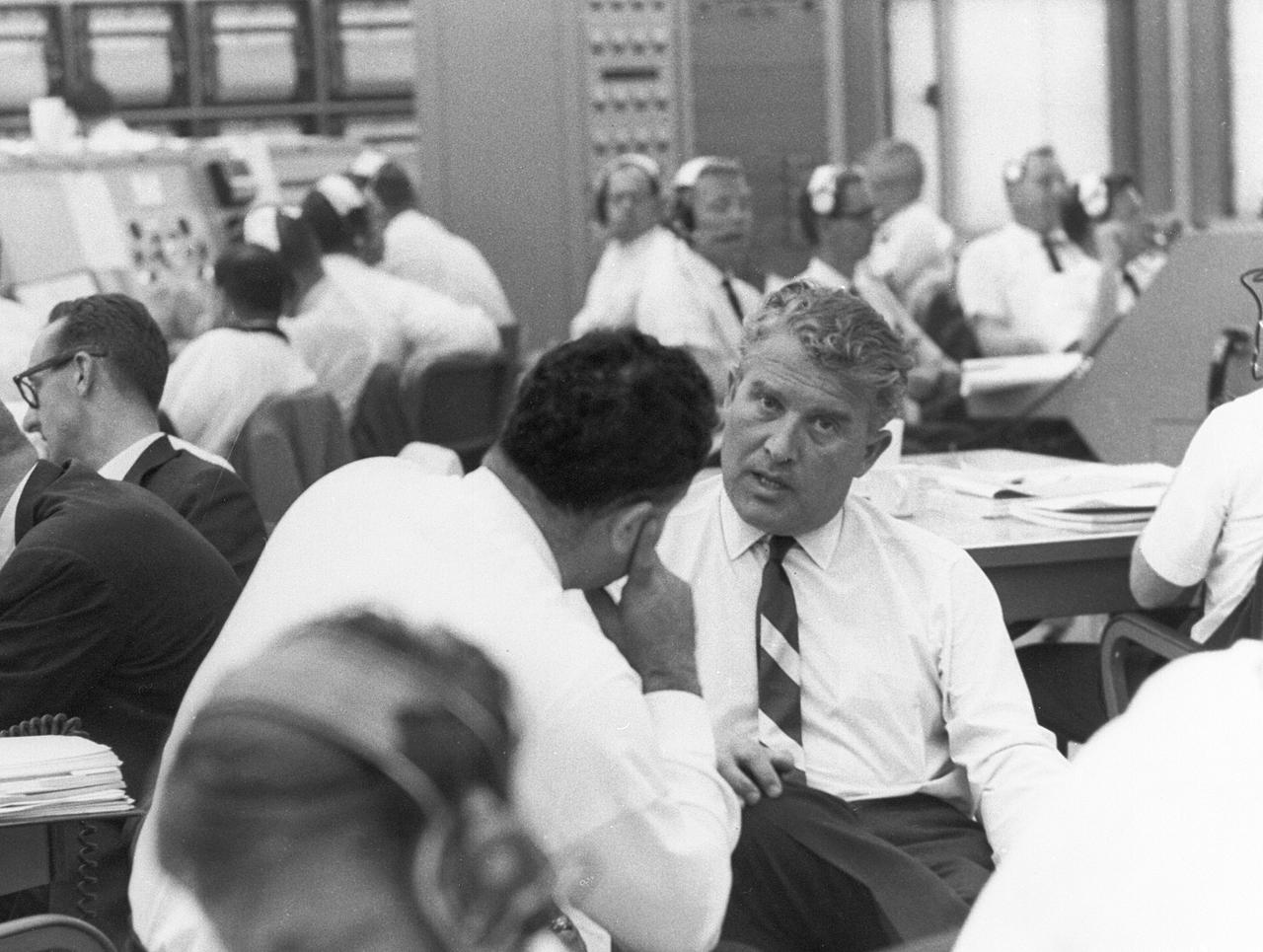
This photograph is not dated. It was probably taken in the late 1960s. Dr. von Braun appears to be in the launch control facilities at the Kennedy Space Center.
A mechanic at the National Aeronautics and Space Administration (NASA) Lewis Research Center prepares the inverted base of a Mercury capsule for a test of its posigrade retrorockets inside the Altitude Wind Tunnel. In October 1959 NASA’s Space Task Group allocated several Project Mercury assignments to Lewis. The Altitude Wind Tunnel was modified to test the Atlas separation system, study the escape tower rocket plume, train astronauts to bring a spinning capsule under control, and calibrate the capsule’s retrorockets. The turning vanes, makeup air pipes, and cooling coils were removed from the wide western end of the tunnel to create a 51-foot diameter test chamber. The Mercury capsule had a six-rocket retro-package affixed to the bottom of the capsule. Three of these were posigrade rockets used to separate the capsule from the booster and three were retrograde rockets used to slow the capsule for reentry into the earth’s atmosphere. Performance of the retrorockets was vital since there was no backup system. Qualification tests of the retrorockets began in April 1960 on a retrograde thrust stand inside the southwest corner of the Altitude Wind Tunnel. These studies showed that a previous issue concerning the delayed ignition of the propellant had been resolved. Follow-up test runs verified reliability of the igniter’s attachment to the propellant. In addition, the capsule’s retrorockets were calibrated so they would not alter the capsule’s attitude when fired.
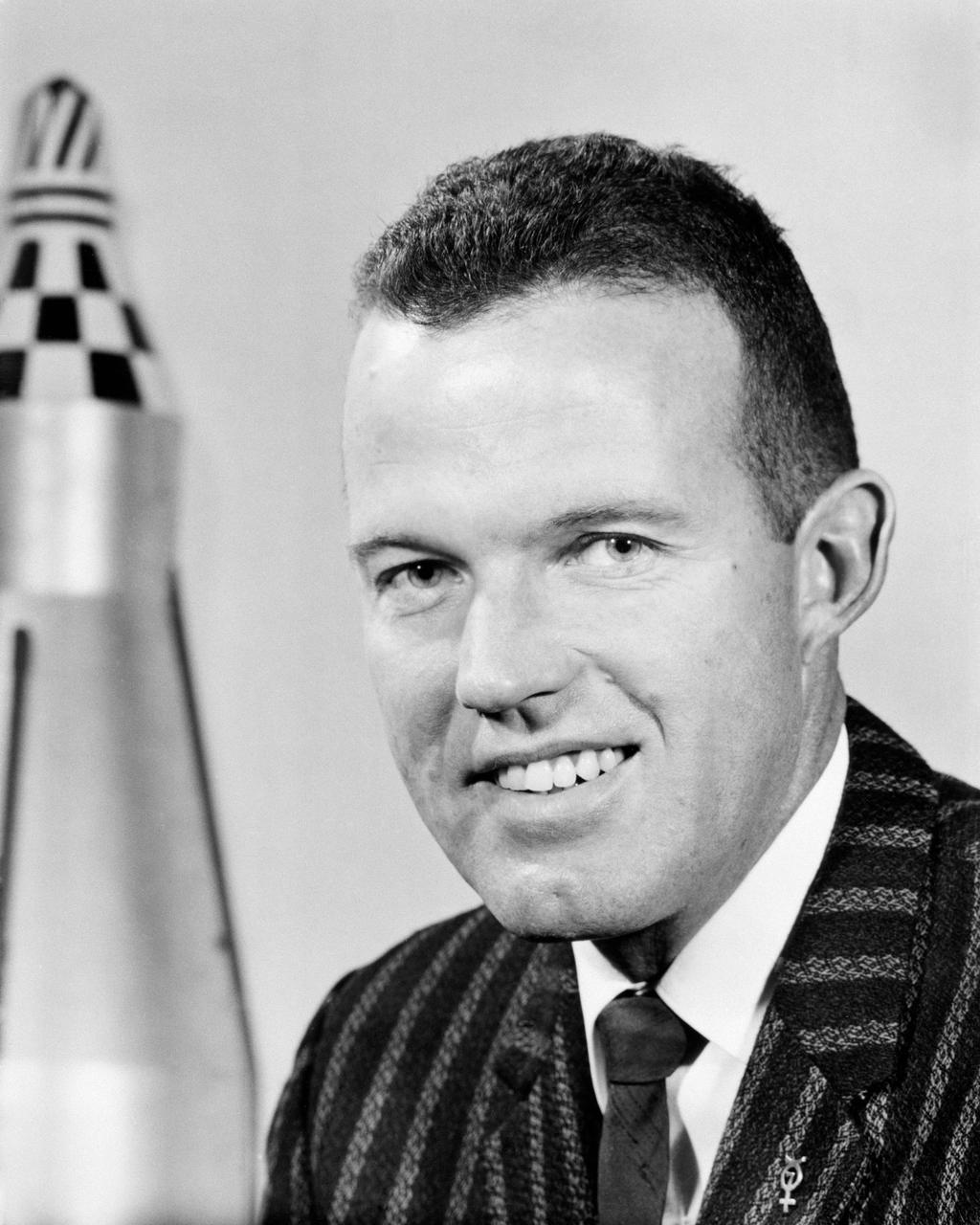
G60-02738 (May 1960) --- Astronaut L. Gordon Cooper Jr. Photo credit: NASA
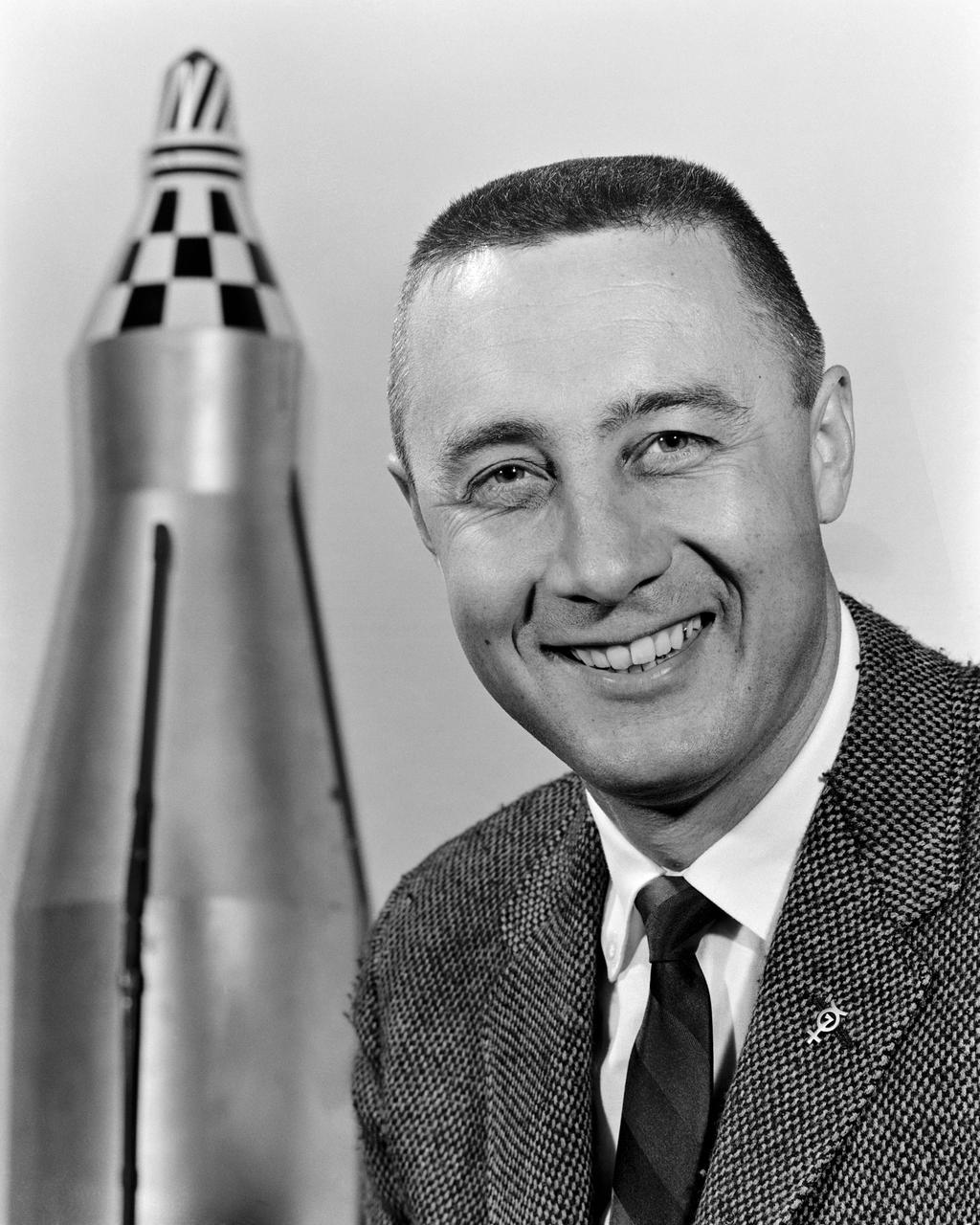
G60-02740 (May 1960) --- Astronaut Virgil I. Grissom. Photo credit: NASA
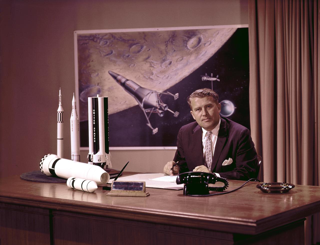
Photo of Marshall Space Flight Center (MSFC) Director Dr. Wernher von Braun at his desk with moon lander in background and rocket models on his desk. Dr. von Braun served as Marshall's first director from 1960 until his transfer to NASA Headquarters in 1970
Model of Winged Space Vehicle
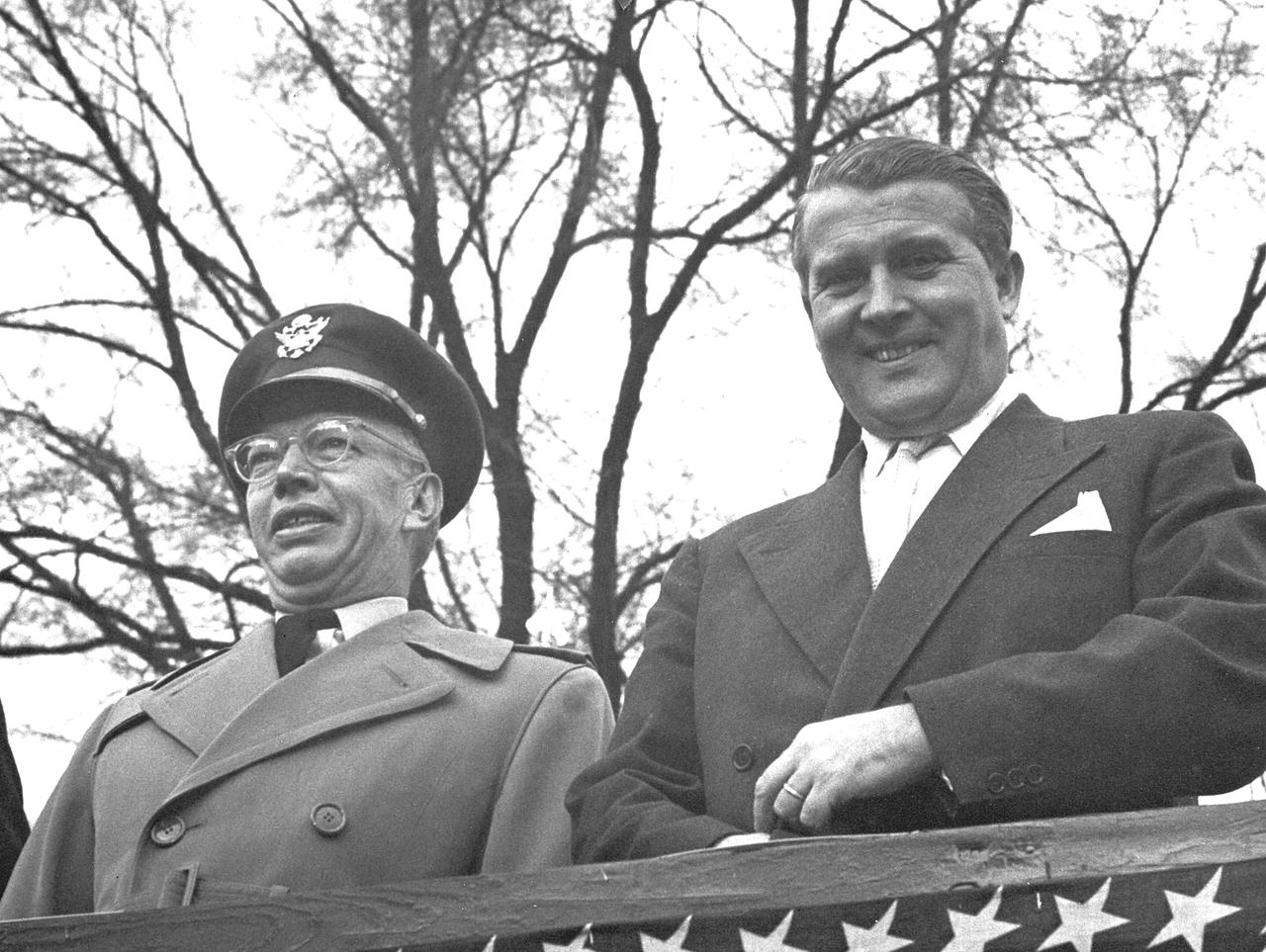
This photograph was taken about 1960 and shows Dr. von Braun viewing a parade with Major General John Barclay.
Model at building 193
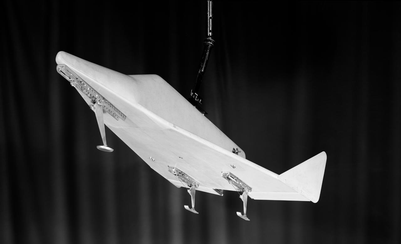
Model of Winged Space Vehicle
G60-02461 (1960) --- Astronaut Walter M. Schirra Jr. prepares to enter gondola of centrifuge which is used to test gravitational stress on astronauts training for spaceflight. Schirra became the pilot of the Mercury-Atlas 8 (MA-8) six-orbit space mission. Photo credit: NASA
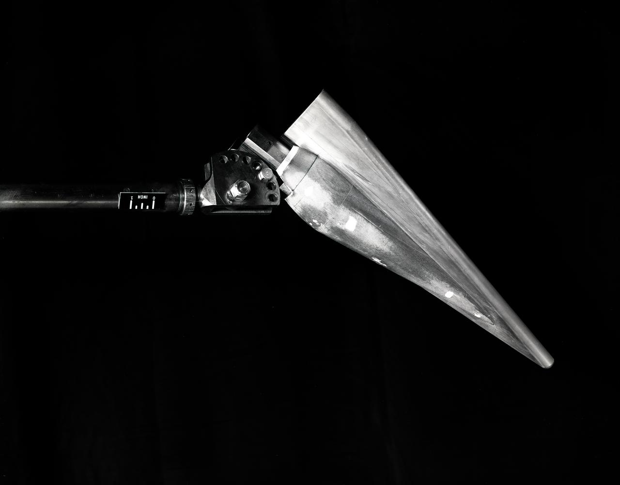
Re-Entry Model
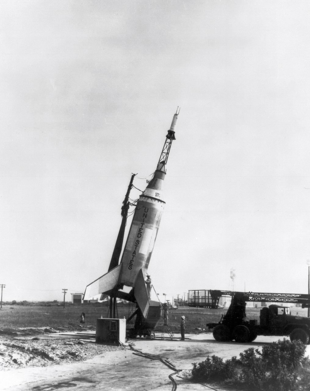
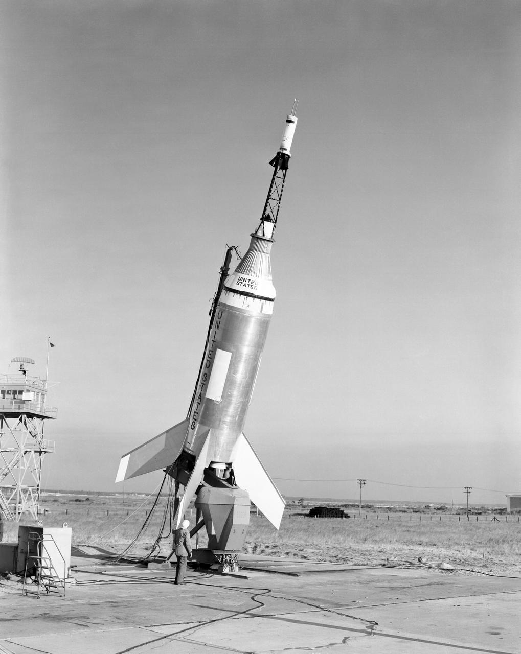
The Little Joe launch vehicle for the LJ1 mission on the launch pad at the wallops Flight Facility, Wallops Island, Virginia, on January 21, 1960. This mission achieved the suborbital Mercury cupsule test, testing of the escape system, and biomedical tests by using a monkey, named Miss Sam.
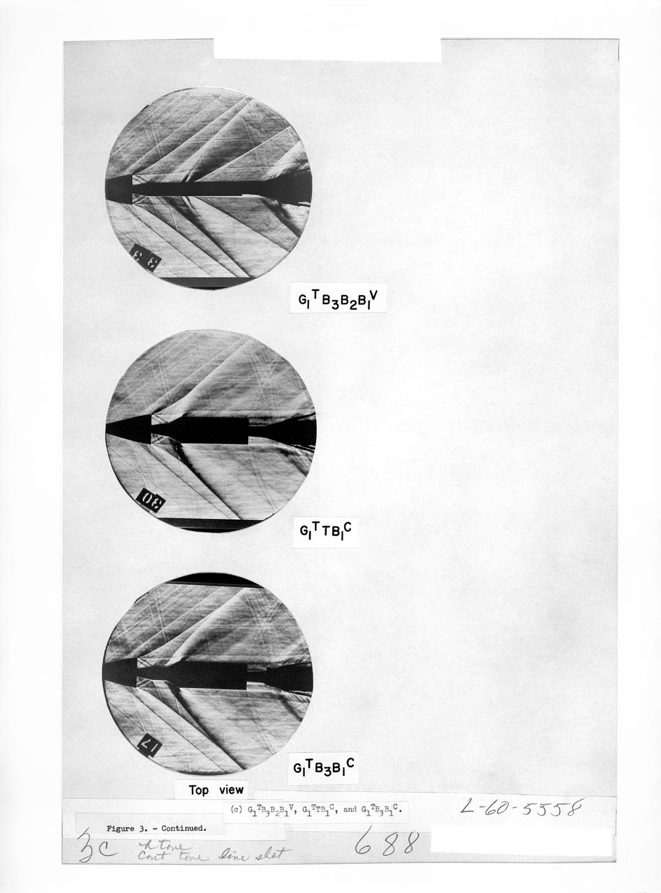
Figure 3-5 for NASA Document TM-X-356

A spider beam for cornecting the Saturn I fuel tanks is being positioned in the fabrication and engineering laboratory of the Marshall Space Flight Center (MSFC).
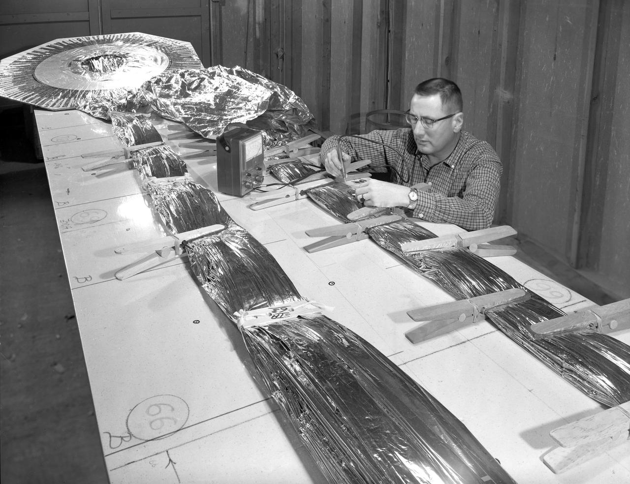
100' Satellite Packaging of Echo
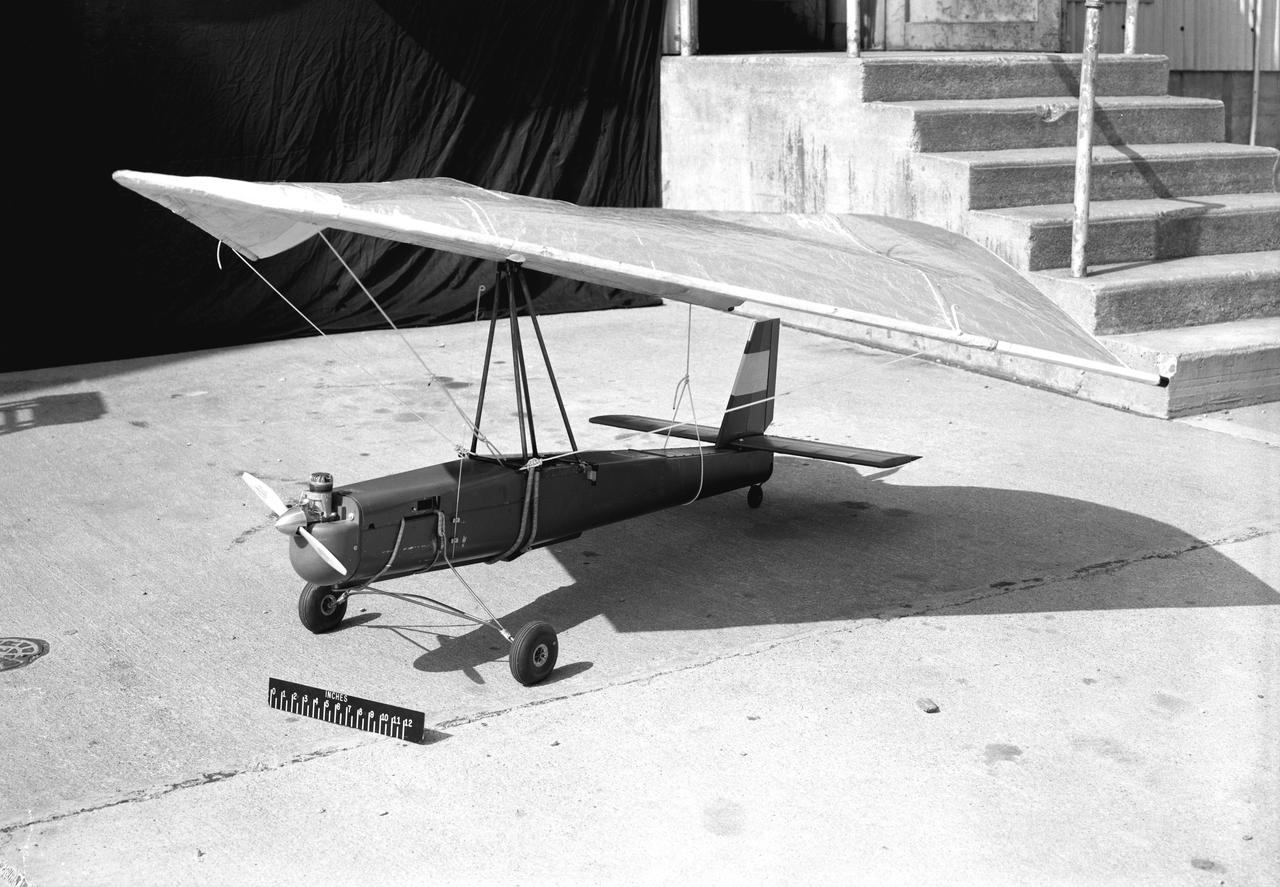
3/4 Low front view of fuselage and fan. Showing jet engine hanging below. Lift fan powered by jet exhaust. General Aerodynamic Characteristics of a Research Model with High Disk Loading Direct Lifting Fan Mounted in Fuselage
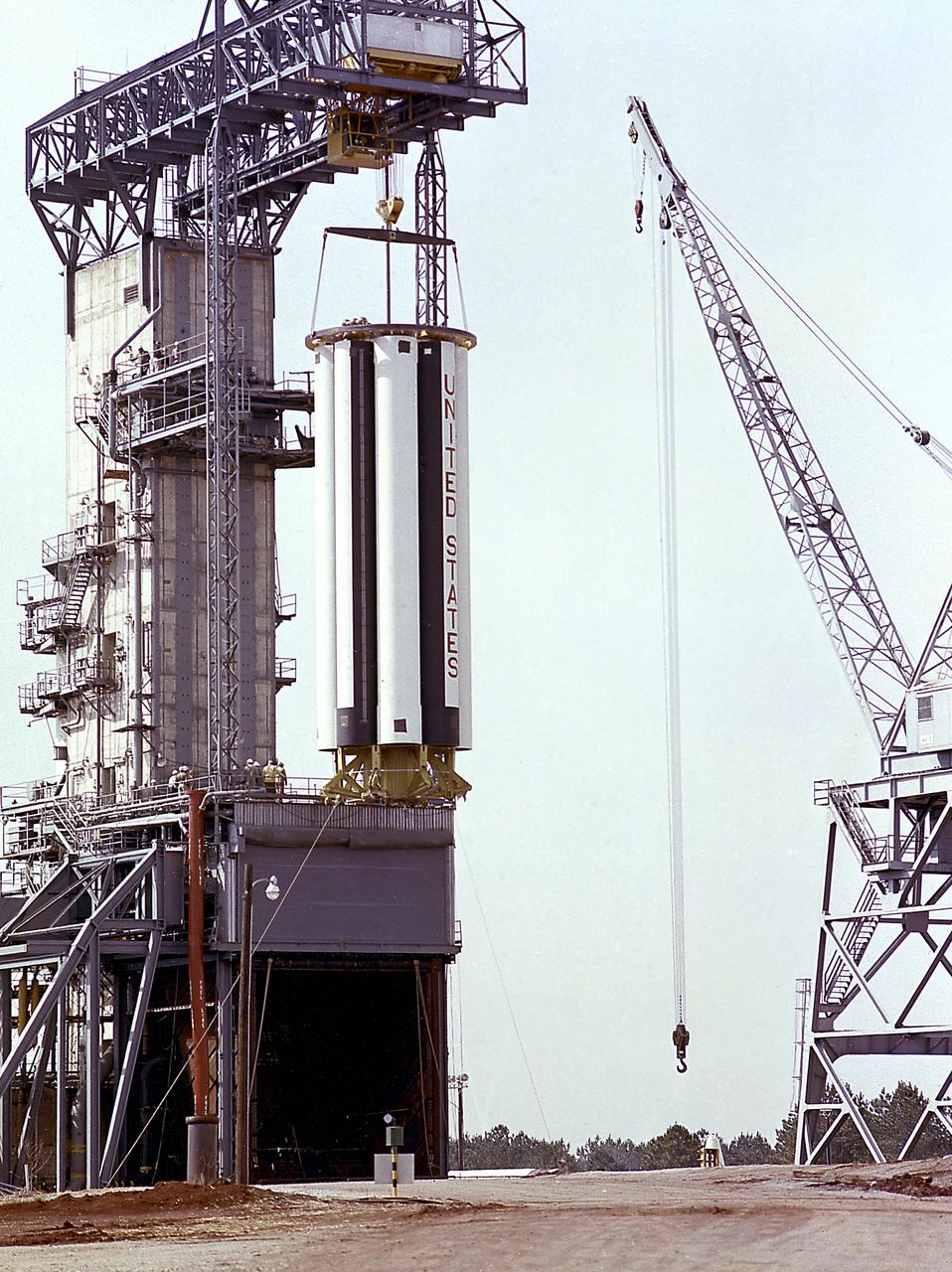
The Saturn Project was approved on January 18, 1960, as a program of the highest national priority. The formal test program to prove out the clustered-booster concept was well underway at Redstone Arsenal. This photograph depicts a mockup of the Saturn booster (S-I stage) being installed in the Army Ballistic Missile Agency (ABMA) test stand, on January 19, 1960, to check mating of the booster and stand and servicing methods.
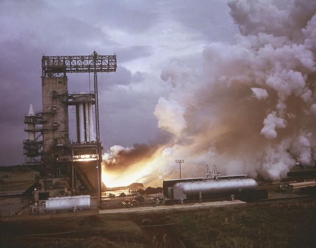
Marshall Space Flight Center (MSFC) was the birthplace of the United States' rocket program. In the early 1960s, most of the rocket development and testing were done at the MSFC. Pictured is an example of what the test engineers would have seen from the pillbox as eight H-1 engines for the first stage of the Saturn I rocket were test fired.
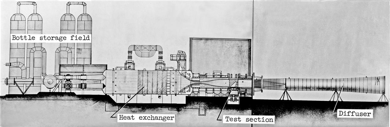
Scale Model of 9x6 Thermal Structures Tunnel: Image L-7256.01 is a Drawing Figure 12 in NASA Document L-1265. The Major components of the 9-by6-Foot Thermal Structures Tunnel. The 97 foot-long diffuser was added in 1960 to reduce noise.
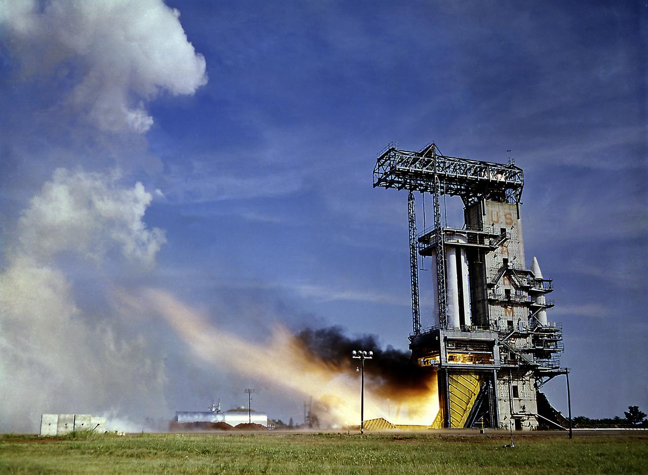
The Saturn Project was approved on January 18, 1960 as a program of the highest national priority. The formal test program to prove out the clustered-booster concept was well underway. A series of static tests of the Saturn I booster (S-I stage) began June 3, 1960 at the Marshall Space Flight Center (MSFC). This photograph depicts the Saturn I S-I stage equipped with eight H-1 engines, being successfully test-fired for the duration of 121 seconds on June 15, 1960.

Aside from native flora, fauna and the Langley rocket-research complex, there was not much on Wallops Island. Pictured is a 1960 photo of Launch area Number Three, used principally for Scout rocket firings. -- Photograph published in Winds of Change, 75th Anniversary NASA publication (page 73), by James Schultz.
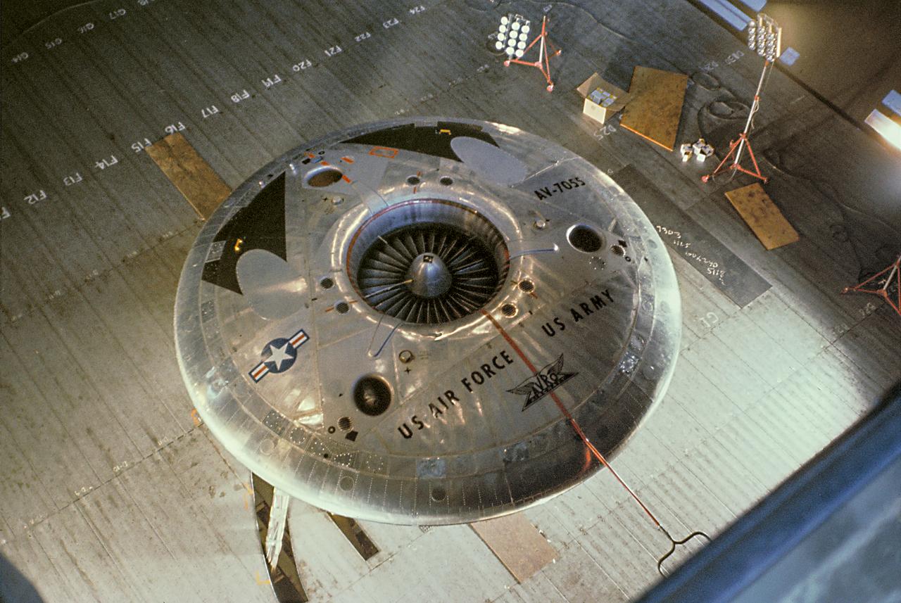
Color view of the Avrocar from overhead in the 40x80 wind tunnel, without A1:H73 mounted on variable height struts.

Doak VTOL Aircraft
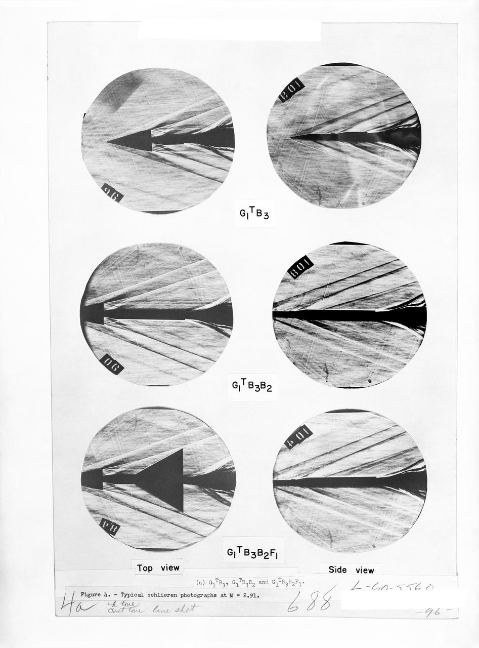
Figure 3-5 for NASA Document TM-X-356
Marshall Space Flight Center (MSFC) workers hoist a dynamic test version of the S-IVB stage, the Saturn IB launch vehicle's second stage, into the Center's Dynamic Test Stand on January 18, 1965. MSFC Test Laboratory persornel assembled a complete Saturn IB to test the launch vehicle's structural soundness. Developed by the MSFC as an interim vehicle in MSFC's "building block" approach to the Saturn rocket development, the Saturn IB utilized Saturn I technology to further develop and refine the larger boosters and the Apollo spacecraft capabilities required for the manned lunar missions.

A Mercury capsule is mounted inside the Altitude Wind Tunnel for a test of its escape tower rockets at the National Aeronautics and Space Administration (NASA) Lewis Research Center. In October 1959 NASA’s Space Task Group allocated several Project Mercury assignments to Lewis. The Altitude Wind Tunnel was quickly modified so that its 51-foot diameter western leg could be used as a test chamber. The final round of tests in the Altitude Wind Tunnel sought to determine if the smoke plume from the capsule’s escape tower rockets would shroud or compromise the spacecraft. The escape tower, a 10-foot steel rig with three small rockets, was attached to the nose of the Mercury capsule. It could be used to jettison the astronaut and capsule to safety in the event of a launch vehicle malfunction on the pad or at any point prior to separation from the booster. Once actuated, the escape rockets would fire, and the capsule would be ejected away from the booster. After the capsule reached its apex of about 2,500 feet, the tower, heatshield, retropackage, and antenna would be ejected and a drogue parachute would be released. Flight tests of the escape system were performed at Wallops Island as part of the series of Little Joe launches. Although the escape rockets fired prematurely on Little Joe’s first attempt in August 1959, the January 1960 follow-up was successful.
From the program’s inception, Neil Armstrong was actively engaged in both the piloting and engineering aspects of the X-15. He flew the first mission using a new flow-direction sensor (ball nose) and the first flight with a self-adaptive flight control system. Collaborating closely with designers and engineers on the system’s development, he made seven flights in the X-15 between December 1960 and July 1962. During these missions, he reached a peak altitude of 207,500 feet in the X-15-3 and a top speed of 3,989 mph (Mach 5.74) in the X-15-1.
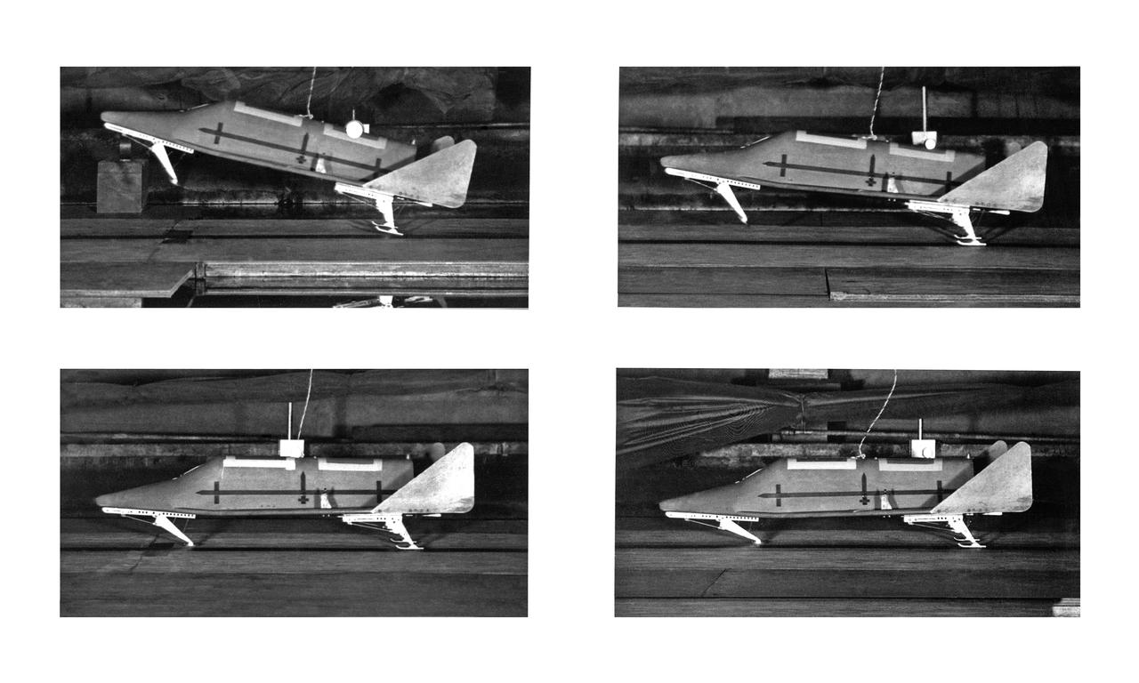
Copy Negative of Sequence Photo Shuttle Model
Model of Winged Space Vehicle
3/4 Low front view of fuselage and fan. Showing jet engine hanging below. Lift fan powered by jet exhaust.
L5-19 (F40-2752) Model in Launch Position
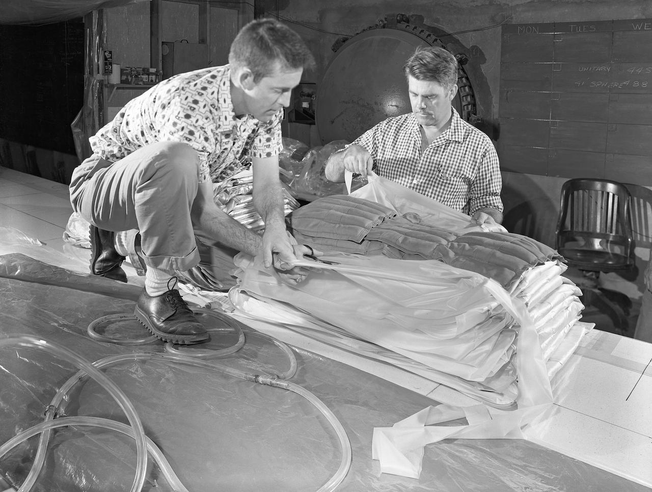
100' Satellite Packaging of Echo
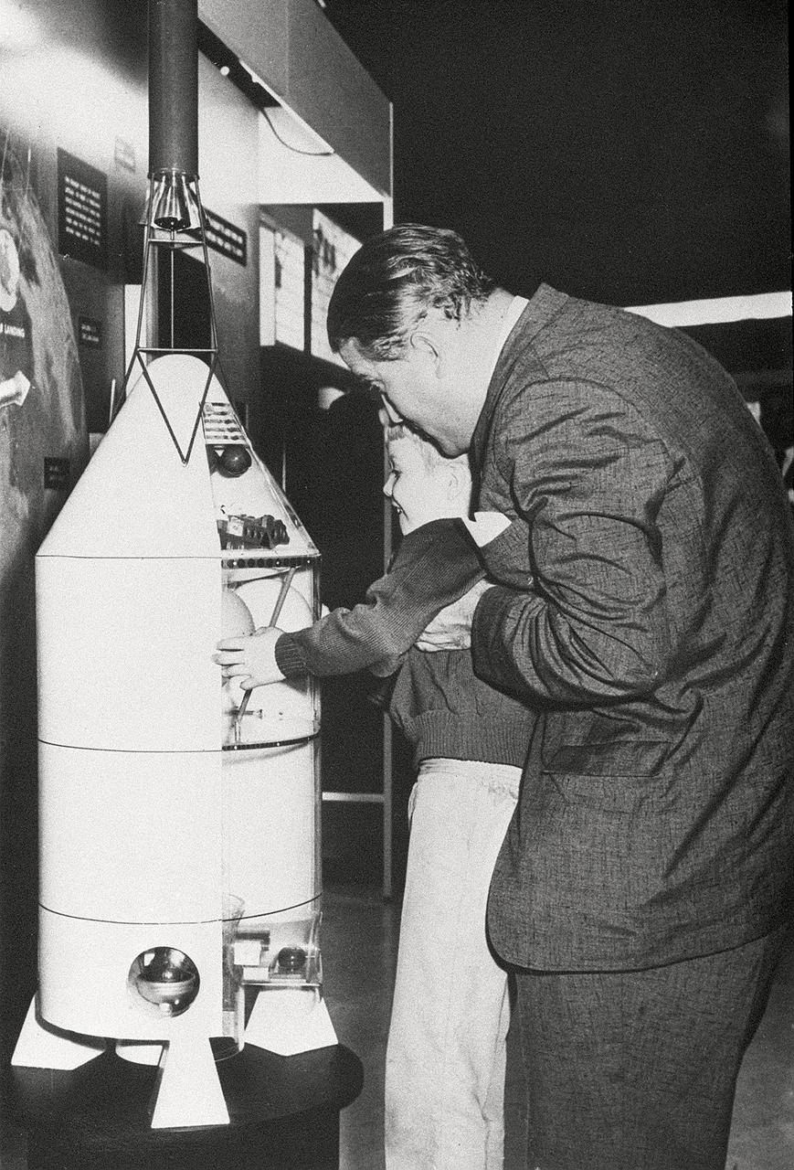
Dr. von Braun always promoted an increased emphasis on education in American culture. He is shown in this photograph with a young boy looking at a space-related exhibit.
Vertol 76 Tilt Wing VTOL. Photographed 9/13/1960. Photograph published in Sixty Years of Aeronautical Research 1917-1977 By David A. Anderton, A NASA publication, Page 62.
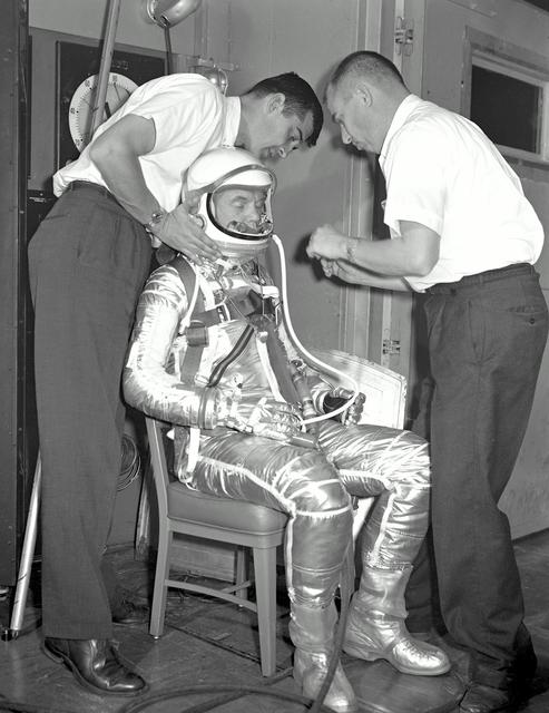
G60-02424 (1960) --- John H. Glenn Jr., one of the seven recently selected Mercury astronauts, participates in a suit-fitting session. Photo credit: NASA
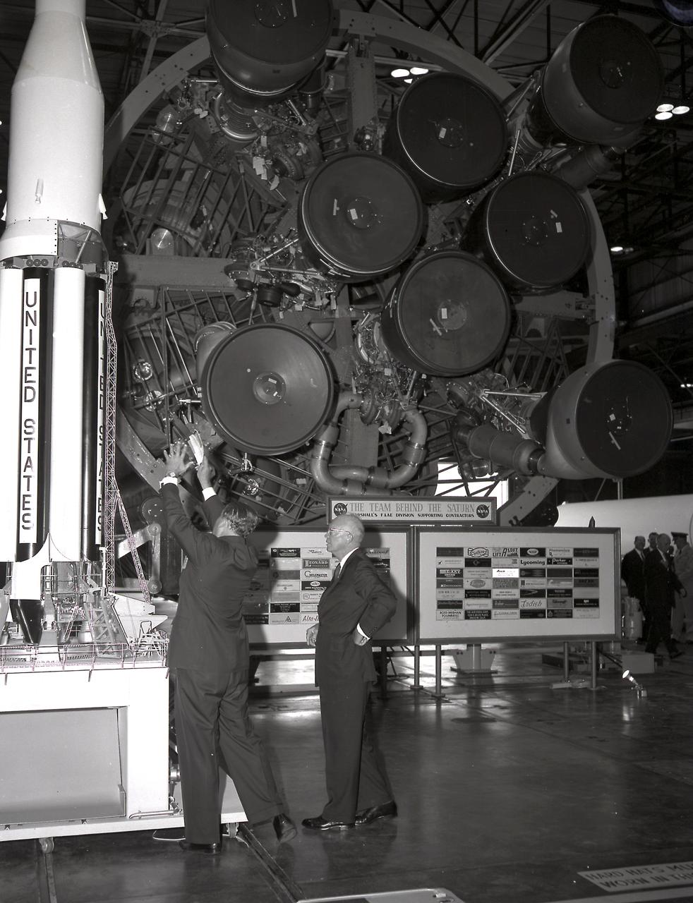
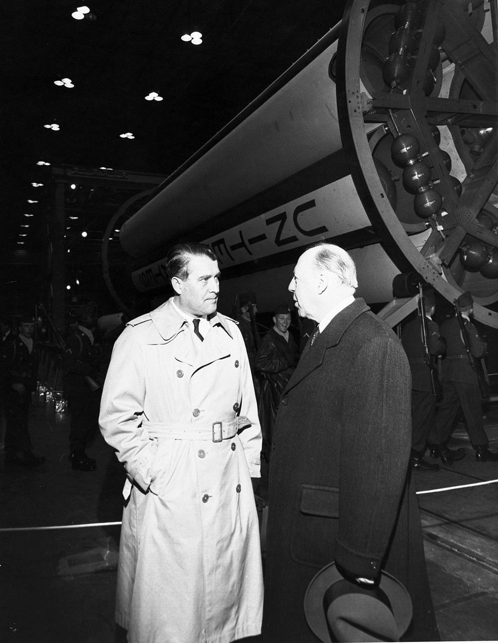
Dr. von Braun briefs President Eisenhower at the front of the S1 Stage (first Stage) of the Saturn 1 vehicle at the Marshall Space Flight Center (MSFC) on September 8, 1960. The President's visit was to dedicate Marshall Space Flight Center as a new NASA field center in honor of General George C. Marshall.
Images take for NASA Document L-1220

3 degree simulator with engineer John Dusterberry
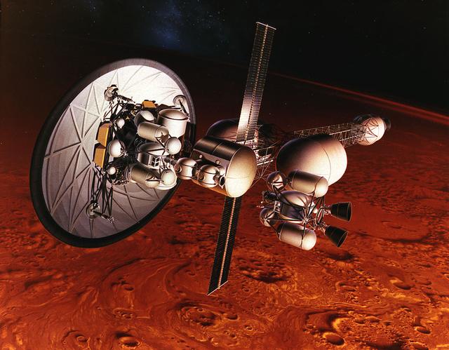
Originally investigated in the 1960's by Marshall Space Flight Center plarners as part of the Nuclear Energy for Rocket Vehicle Applications (NERVA) program, nuclear-thermal rocket propulsion has been more recently considered in spacecraft designs for interplanetary human exploration. This artist's concept illustrates a nuclear-thermal rocket with an aerobrake disk as it orbits Mars.
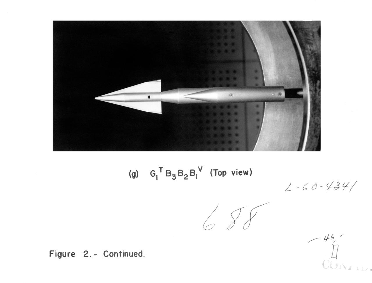
Photos of the eleven booster configurations