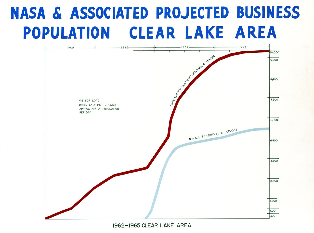
NASA & ASSOCIATED PROJECTED BUSINESS POPULATION - CLEAR LAKE AREA - 1962 - 1965
CAPE CANAVERAL, FLA. -- Hangar 'S' -- Mercury workers and news media are greeted by astronaut L. Gordon Cooper as he leaves Hangar 'S' for Pad 14 to start his 22-orbit mission, MA-9.
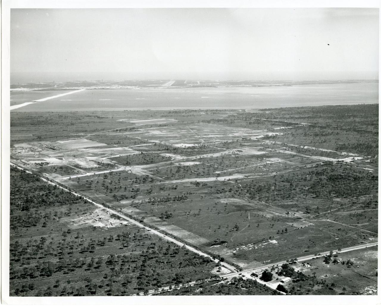
CAPE CANAVERAL, Fla. -- This aerial of view from 1963 shows the site of the Industrial Area for the Merritt Island Launch Annex, now the Kennedy Space Center in Florida. Located five miles south of Launch Complex 39, this is the site where facilities were built such as the Headquarters Building, Operations and Checkout Building as well as the Central Instrumentation Facility. Photo Credit: NASA.
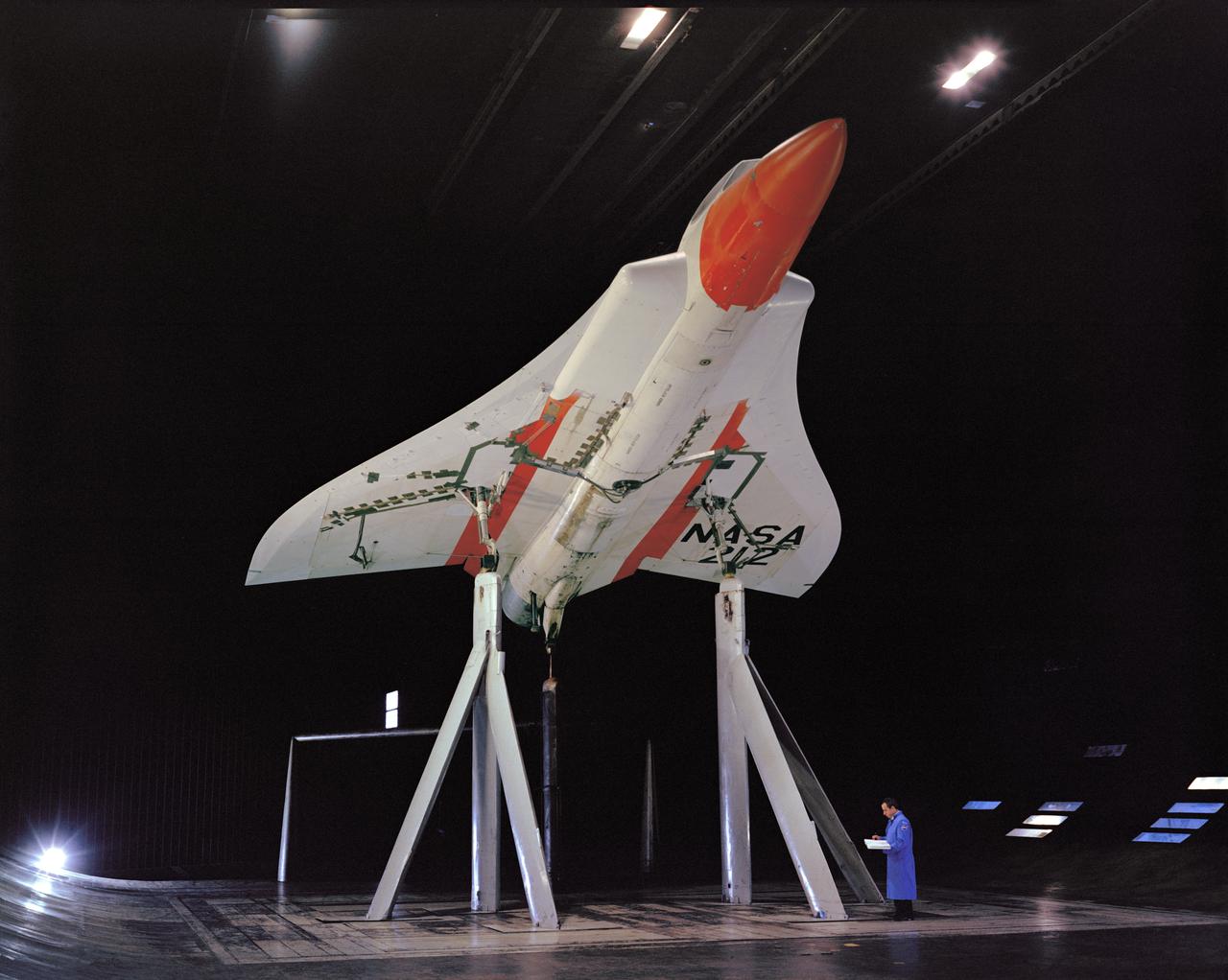
M-2 Lifting body 40x80ft Full Scale Wind Tunnle
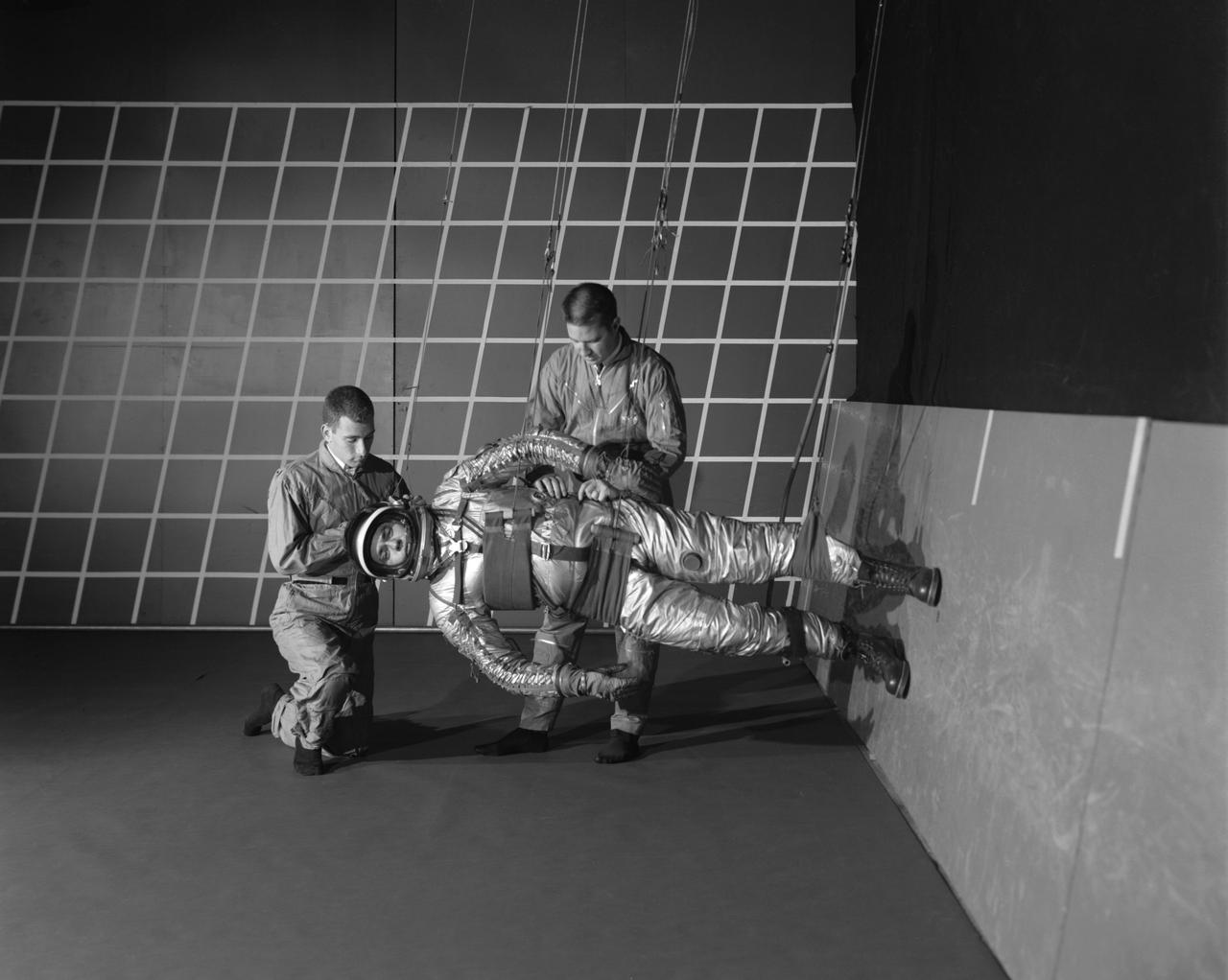
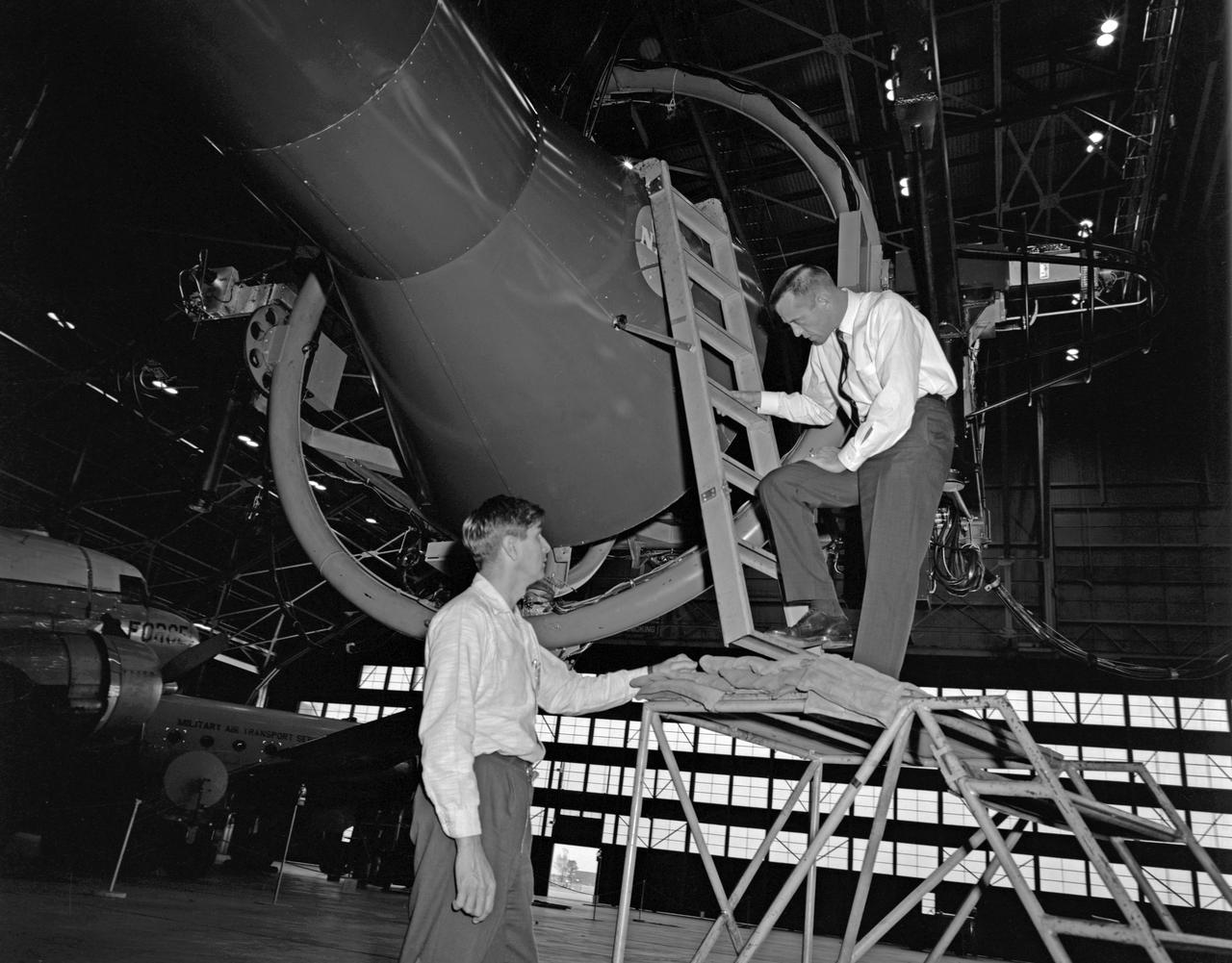
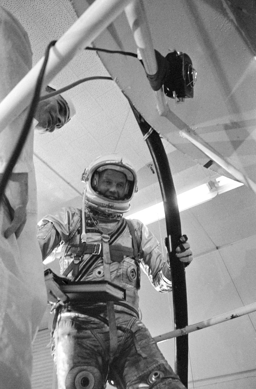
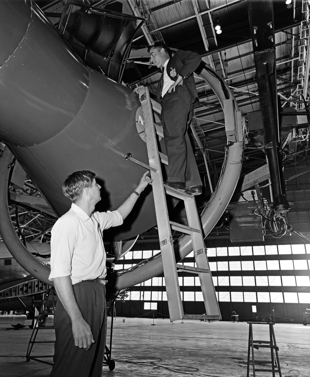
A test subject being suited up for studies on the Reduced Gravity Walking Simulator located in the hangar at Langley Research Center. The initial version of this simulator was located inside the hangar. Later a larger version would be located at the Lunar Landing Facility. The purpose of this simulator was to study the subject while walking, jumping or running. Researchers conducted studies of various factors such as fatigue limit, energy expenditure, and speed of locomotion. Francis B. Smith wrote in his paper "Simulators For Manned Space Research," "I would like to conclude this talk with a discussion of a device for simulating lunar gravity which is very effective and yet which is so simple that its cost is in the order of a few thousand dollars at most, rather than hundreds of thousands. With a little ingenuity, one could almost build this type simulator in his backyard for children to play on. The principle is ...if a test subject is suspended in a sling so that his body axis makes an angle of 9 1/2 degrees with the horizontal and if he then "stands" on a platform perpendicular to his body axis, the component of the earth's gravity forcing him toward the platform is one times the sine of 9 1/2 degrees or approximately 1/6 of the earth's normal gravity field. That is, a 180 pound astronaut "standing" on the platform would exert a force of only 30 pounds - the same as if he were standing upright on the lunar surface." -- Published in James R. Hansen, Spaceflight Revolution: NASA Langley Research Center From Sputnik to Apollo, NASA SP-4308; Francis B. Smith, "Simulators For Manned Space Research," Paper for 1966 IEEE International Convention, New York, NY, March 21-25, 1966
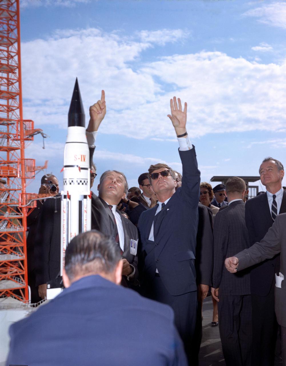
KENNEDY SPACE CENTER, FLA. -- Dr. Werner Von Braun explains the Saturn system to President John F. Kennedy at Complex 37 while President Kennedy is on tour at the Cape Canaveral Missile Test Annex.
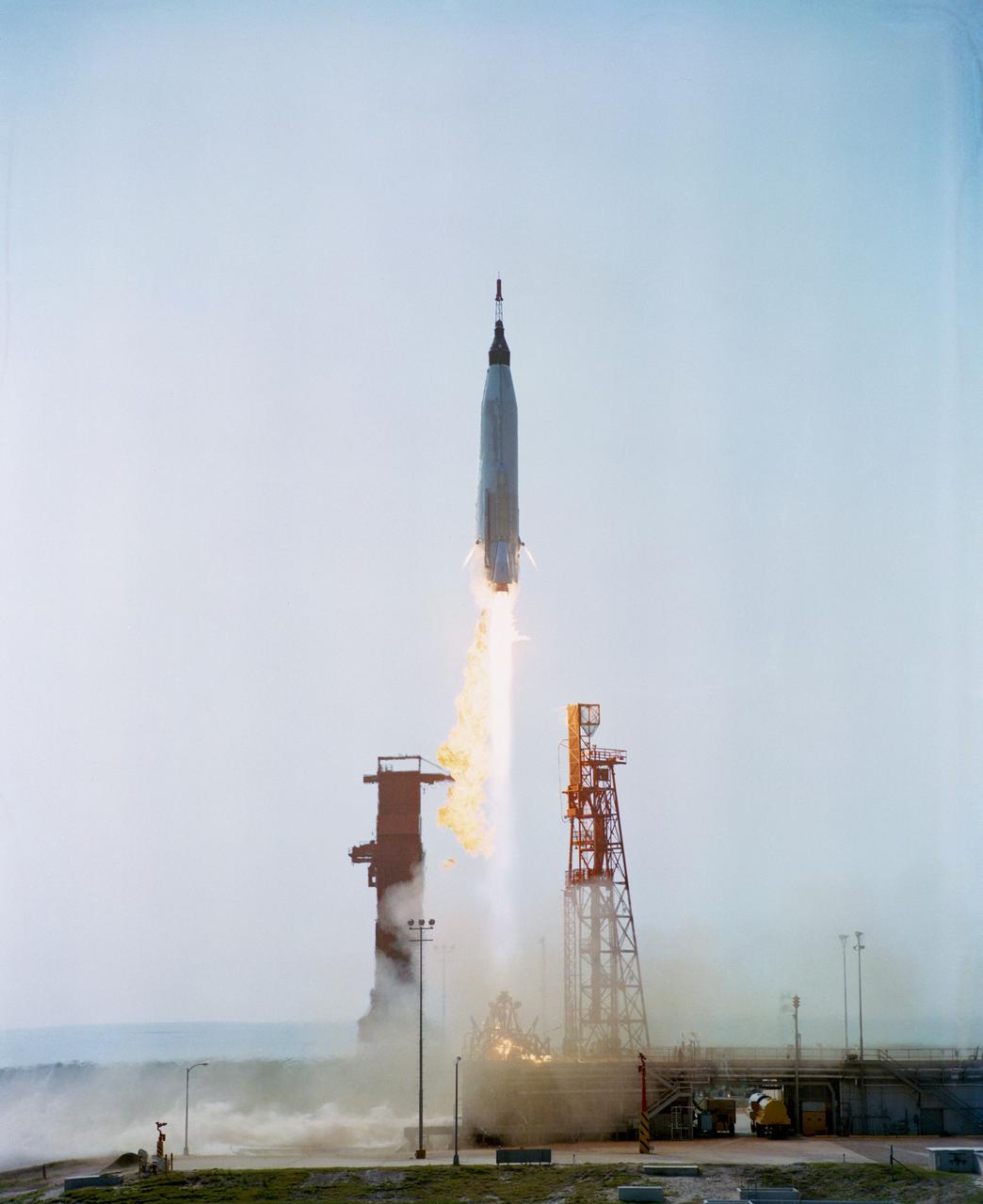
S63-00193 (29 July 1960) --- Launch of the unmanned Mercury-Atlas 1 (MA-1) from Cape Canaveral, Florida. Premature engine cutoff at launch terminated the test. Emergency escape system jettisoned. The Altas exploded 65 seconds after launch. Photo credit: NASA
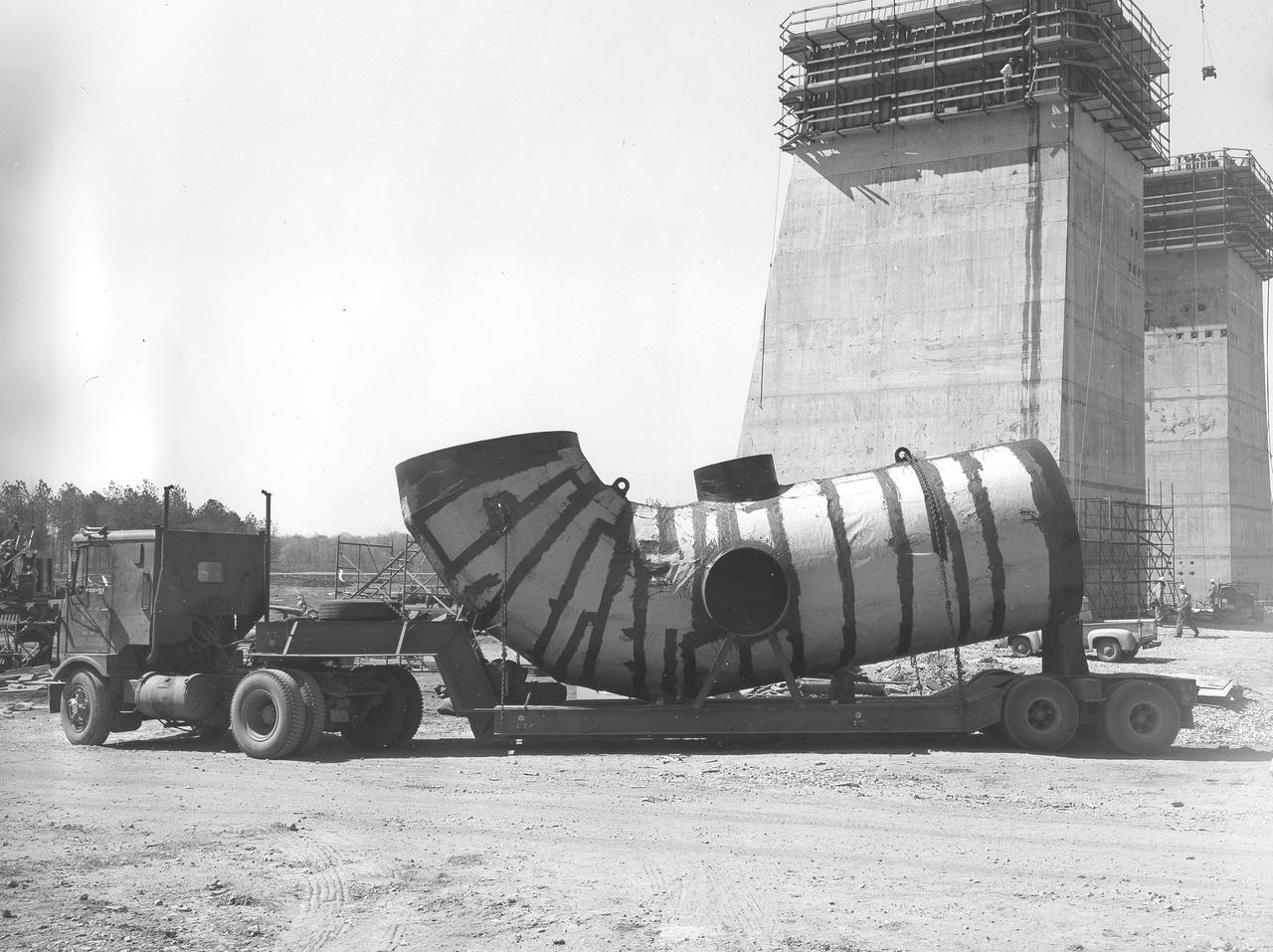
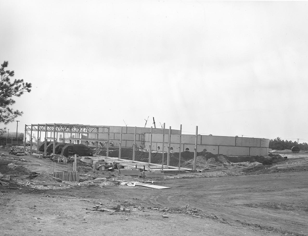
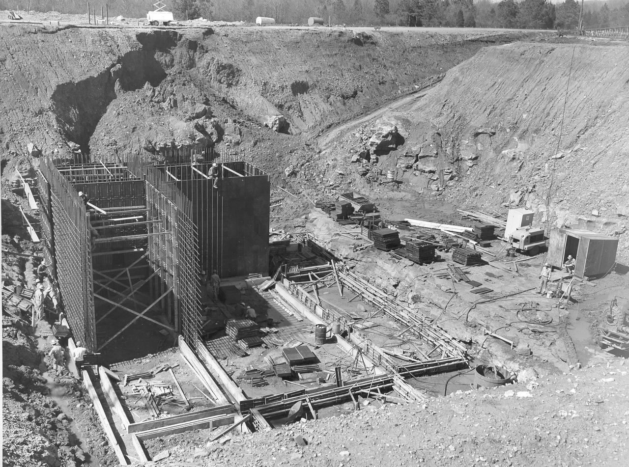
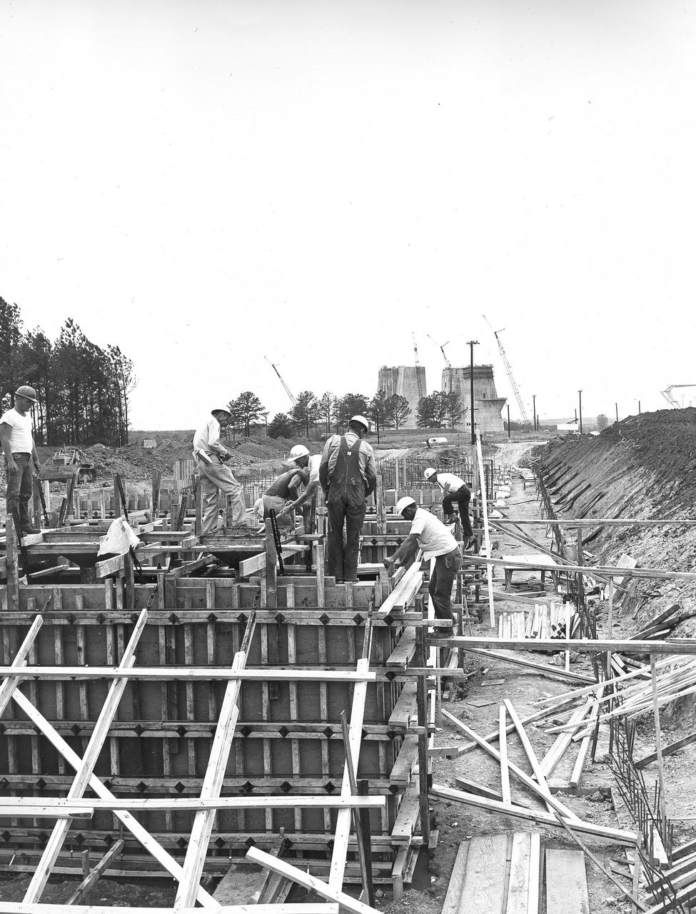
At its founding, the Marshall Space Flight Center (MSFC) inherited the Army’s Jupiter and Redstone test stands, but much larger facilities were needed for the giant stages of the Saturn V. From 1960 to 1964, the existing stands were remodeled and a sizable new test area was developed. The new comprehensive test complex for propulsion and structural dynamics was unique within the nation and the free world, and they remain so today because they were constructed with foresight to meet the future as well as on going needs. Construction of the S-IC Static test stand complex began in 1961 in the west test area of MSFC, and was completed in 1964. The S-IC static test stand was designed to develop and test the 138-ft long and 33-ft diameter Saturn V S-IC first stage, or booster stage, weighing in at 280,000 pounds. Required to hold down the brute force of a 7,500,000-pound thrust produced by 5 F-1 engines, the S-IC static test stand was designed and constructed with the strength of hundreds of tons of steel and 12,000,000 pounds of cement, planted down to bedrock 40 feet below ground level. The foundation walls, constructed with concrete and steel, are 4 feet thick. The base structure consists of four towers with 40-foot-thick walls extending upward 144 feet above ground level. The structure was topped by a crane with a 135-foot boom. With the boom in the upright position, the stand was given an overall height of 405 feet, placing it among the highest structures in Alabama at the time. In addition to the stand itself, related facilities were constructed during this time. Built directly east of the test stand was the Block House, which served as the control center for the test stand. The two were connected by a narrow access tunnel which housed the cables for the controls. Again to the east, just south of the Block House, was a newly constructed Pump House. Its function was to provide water to the stand to prevent melting damage during testing. The water was sprayed through small holes in the stand’s 1900 ton water deflector at the rate of 320,000 gallons per minute. This photo, taken April 4, 1963, depicts the portion of the massive water line that was installed into the S-IC test Stand.
Astronaut Alan Shepard (right) was one of 14 astronauts, 8 NASA test pilots, and 2 McDonnell test pilots who took part in simulator studies. Shepard flew the simulator on November 14, 1963. A.W. Vogeley wrote: "Many of the astronauts have flown this simulator in support of the Gemini studies and they, without exception, appreciated the realism of the visual scene. The simulator has also been used in the development of pilot techniques to handle certain jet malfunctions in order that aborts could be avoided. In these situations large attitude changes are sometimes necessary and the false motion cues that were generated due to earth gravity were somewhat objectionable; however, the pilots were readily able to overlook these false motion cues in favor of the visual realism." Roy F. Brissenden noted that: "The basic Gemini control studies developed the necessary techniques and demonstrated the ability of human pilots to perform final space docking with the specified Gemini-Agena systems using only visual references. ... Results... showed that trained astronauts can effect the docking with direct acceleration control and even with jet malfunctions as long as good visual conditions exist.... Probably more important than data results was the early confidence that the astronauts themselves gained in their ability to perform the maneuver in the ultimate flight mission." Shepard commented: "I had the feeling tonight - a couple of times - that I was actually doing the space mission instead of the simulation. As I said before, I think it is a very good simulation." Shepard also commented on piloting techniques. Most astronauts arrived at this same preferred technique: Shepard: "I believe I have developed the preferred technique for these conditions and the technique appeared to me to be best was to come in slightly above the target so that I was able to use the longitudinal marks on the body of the target as a reference, particularly for a lateral translation and, of course, I used the foreshortening effect for a vertical translation, and this appeared to give me the best results. By that I mean the least number of control motions and the lowest fuel usage and the best end techniques, or the best end conditions, I should say." Engineer: "When you started to run you didn't start thrusting immediately I don't believe. It looked like you started working on your attitudes, then started closing in." Shepard: "That is correct. I did that because I felt that I wanted to get the X-axis translation in the most effective vector and for minimum fuel usage that wouldn't introduce any other lateral or vertical offsets that did not already exist." -- Published in Barton C. Hacker and James M. Grimwood, On the Shoulders of Titans: A History of Project Gemini, NASA SP-4203; A.W. Vogeley, "Discussion of Existing and Planned Simulators For Space Research," Paper presented at the Conference on the Role of Simulation in Space Technology, August 17-21, 1964; Roy F. Brissenden, "Initial Operations with Langley's Rendezvous Docking Facility," Langley Working Paper, LWP-21, 1964.
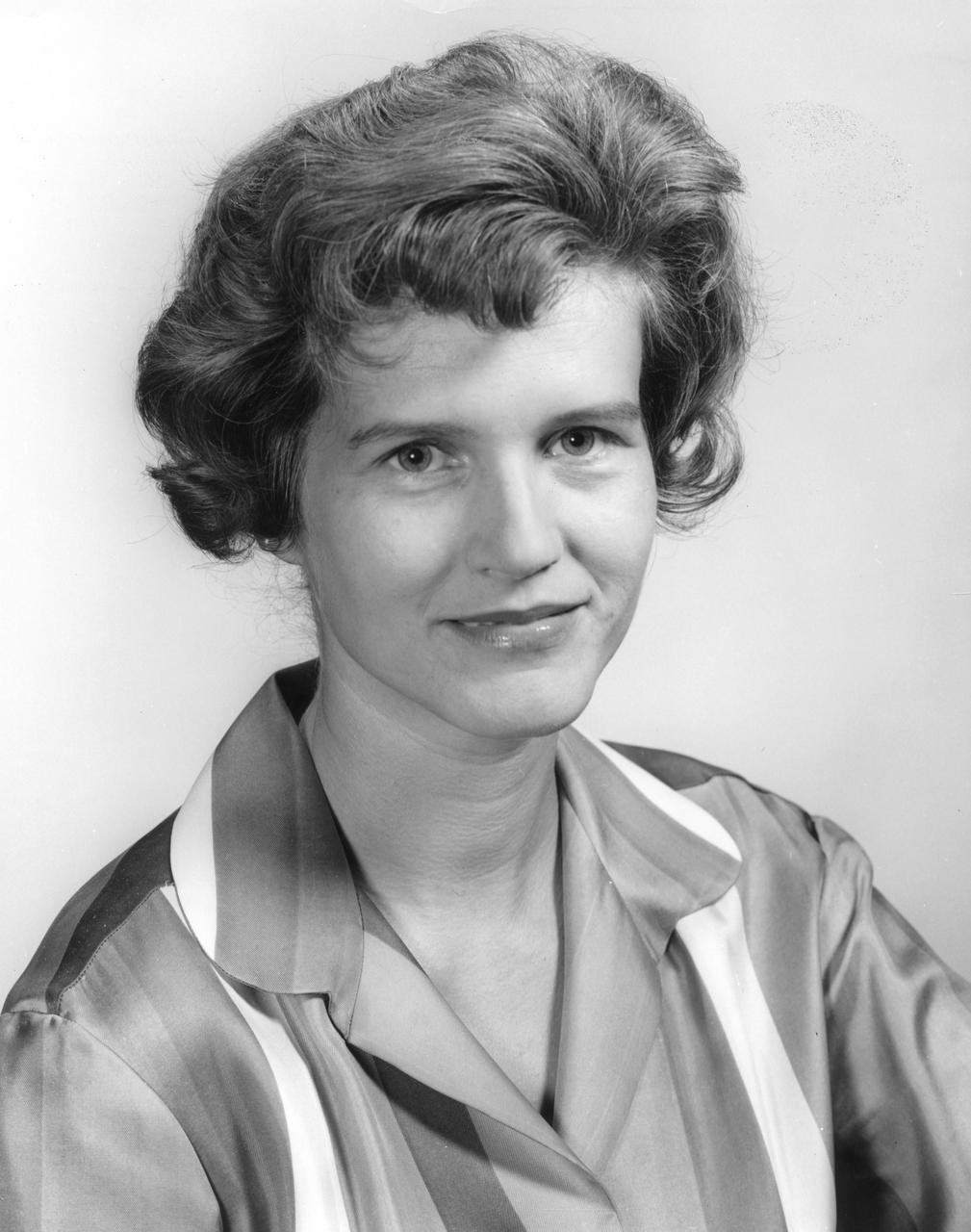
This is a portrait of Maria von Braun, wife of the famous Marshall Space Flight Center (MSFC) director Wernher von Braun. Her husband, Wernher, who led America to the Moon, served as MSFC’s first director from July 1, 1960 until January 27, 1970.
5 Degree of Freedom - Manned Flight Simulator
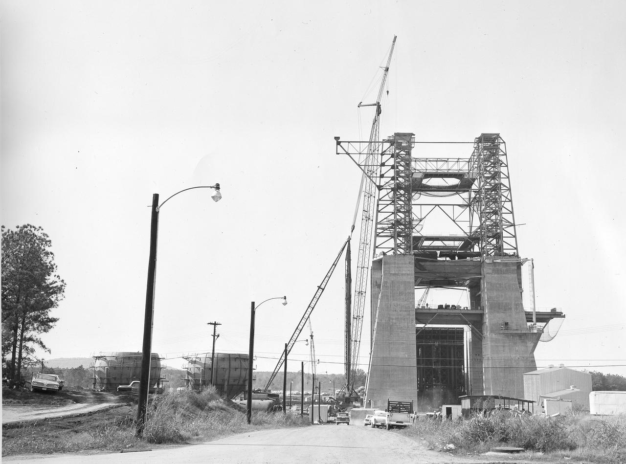
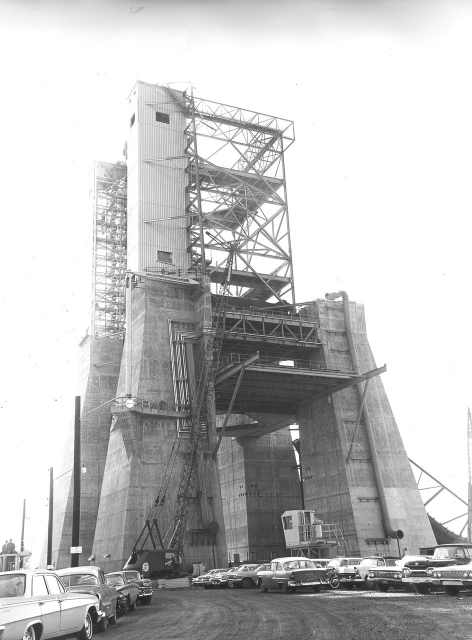
At its founding, the Marshall Space Flight Center (MSFC) inherited the Army’s Jupiter and Redstone test stands, but much larger facilities were needed for the giant stages of the Saturn V. From 1960 to 1964, the existing stands were remodeled and a sizable new test area was developed. The new comprehensive test complex for propulsion and structural dynamics was unique within the nation and the free world, and they remain so today because they were constructed with foresight to meet the future as well as on going needs. Construction of the S-IC Static test stand complex began in 1961 in the west test area of MSFC, and was completed in 1964. The S-IC static test stand was designed to develop and test the 138-ft long and 33-ft diameter Saturn V S-IC first stage, or booster stage, weighing in at 280,000 pounds. Required to hold down the brute force of a 7,500,000-pound thrust produced by 5 F-1 engines, the S-IC static test stand was designed and constructed with the strength of hundreds of tons of steel and 12,000,000 pounds of cement, planted down to bedrock 40 feet below ground level. The foundation walls, constructed with concrete and steel, are 4 feet thick. The base structure consists of four towers with 40-foot-thick walls extending upward 144 feet above ground level. The structure was topped by a crane with a 135-foot boom. With the boom in the upright position, the stand was given an overall height of 405 feet, placing it among the highest structures in Alabama at the time. This photograph, taken April 4, 1963, gives a close up look at the ever-growing four towers of the S-IC Test Stand.
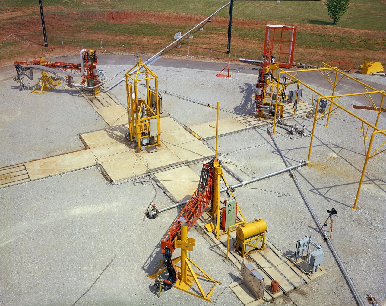
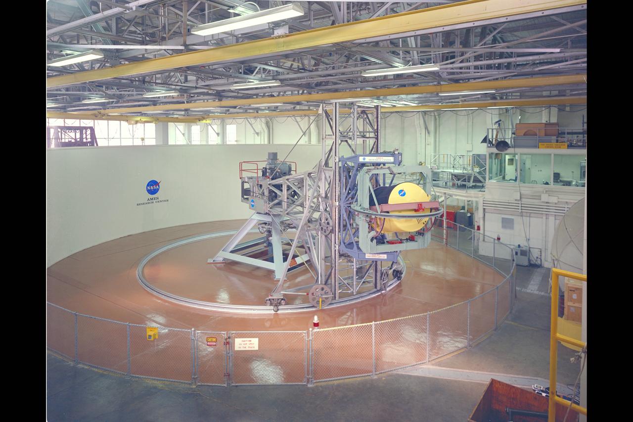
The Marshall Space Flight Center (MSFC) played a crucial role in the development of the huge Saturn rockets that delivered humans to the moon in the 1960s. Many unique facilities existed at MSFC for the development and testing of the Saturn rockets. Affectionately nicknamed “The Arm Farm”, the Random Motion/ Lift-Off Simulator was one of those unique facilities. This facility was developed to test the swingarm mechanisms that were used to hold the rocket in position until lift-off. The Arm Farm provided the capability of testing the detachment and reconnection of various arms under brutally realistic conditions. The 18-acre facility consisted of more than a half dozen arm test positions and one position for testing access arms used by the Apollo astronauts. Each test position had two elements: a vehicle simulator for duplicating motions during countdown and launch; and a section duplicating the launch tower. The vehicle simulator duplicated the portion of the vehicle skin that contained the umbilical connections and personnel access hatches. Driven by a hydraulic servo system, the vehicle simulator produced relative motion between the vehicle and tower. On the Arm Farm, extreme environmental conditions (such as a launch scrub during an approaching Florida thunderstorm) could be simulated. The dramatic scenes that the Marshall engineers and technicians created at the Arm Farm permitted the gathering of crucial technical and engineering data to ensure a successful real time launch from the Kennedy Space Center.
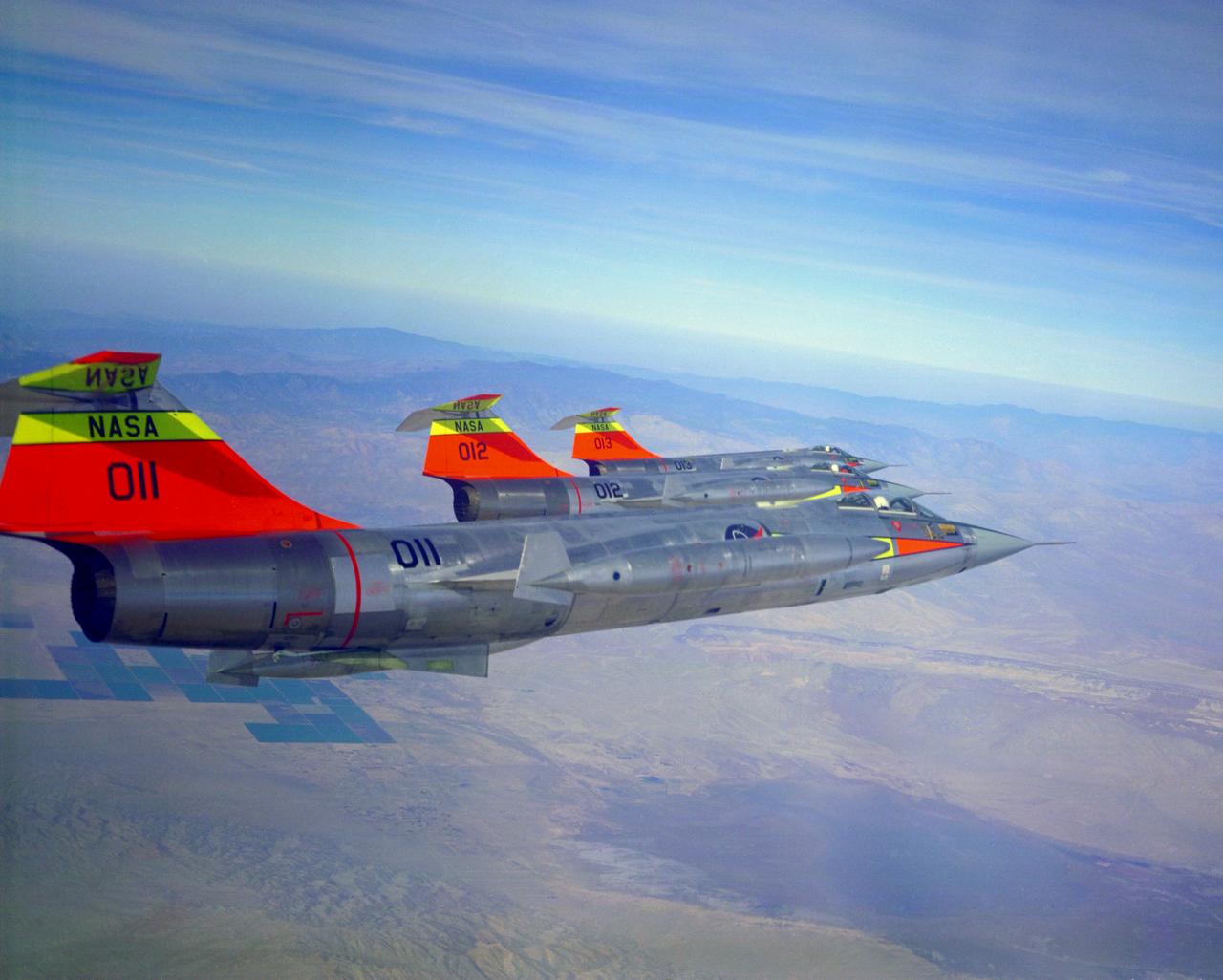
All three NASA F-104N's fly in formation. Aircraft numbers 011, 012 and 013. These would be changed to 811, 812 and 813 in 1965. Pilots are Bruce Peterson in 011, Milt Thompson in 012 and Joe Walker in 013. October 24, 1963
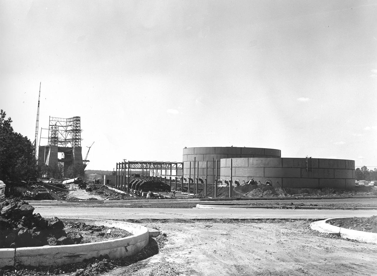
At its founding, the Marshall Space Flight Center (MSFC) inherited the Army’s Jupiter and Redstone test stands, but much larger facilities were needed for the giant stages of the Saturn V. From 1960 to 1964, the existing stands were remodeled and a sizable new test area was developed. The new comprehensive test complex for propulsion and structural dynamics was unique within the nation and the free world, and they remain so today because they were constructed with foresight to meet the future as well as on going needs. Construction of the S-IC Static test stand complex began in 1961 in the west test area of MSFC, and was completed in 1964. The S-IC static test stand was designed to develop and test the 138-ft long and 33-ft diameter Saturn V S-IC first stage, or booster stage, weighing in at 280,000 pounds. Required to hold down the brute force of a 7,500,000-pound thrust produced by 5 F-1 engines, the S-IC static test stand was designed and constructed with the strength of hundreds of tons of steel and 12,000,000 pounds of cement, planted down to bedrock 40 feet below ground level. The foundation walls, constructed with concrete and steel, are 4 feet thick. The base structure consists of four towers with 40-foot-thick walls extending upward 144 feet above ground level. The structure was topped by a crane with a 135-foot boom. With the boom in the upright position, the stand was given an overall height of 405 feet, placing it among the highest structures in Alabama at the time. In addition to the stand itself, related facilities were constructed during this time. Built to the northeast of the stand was a newly constructed Pump House. Its function was to provide water to the stand to prevent melting damage during testing. The water was sprayed through small holes in the stand’s 1900 ton flame deflector at the rate of 320,000 gallons per minute. This close up photograph, taken September 5, 1963, shows the ground level frame work for the Pump House and its massive round water storage tanks.
At its founding, the Marshall Space Flight Center (MSFC) inherited the Army’s Jupiter and Redstone test stands, but much larger facilities were needed for the giant stages of the Saturn V. From 1960 to 1964, the existing stands were remodeled and a sizable new test area was developed. The new comprehensive test complex for propulsion and structural dynamics was unique within the nation and the free world, and they remain so today because they were constructed with foresight to meet the future as well as on going needs. Construction of the S-IC Static test stand complex began in 1961 in the west test area of MSFC, and was completed in 1964. The S-IC static test stand was designed to develop and test the 138-ft long and 33-ft diameter Saturn V S-IC first stage, or booster stage, weighing in at 280,000 pounds. Required to hold down the brute force of a 7,500,000-pound thrust produced by 5 F-1 engines, the S-IC static test stand was designed and constructed with the strength of hundreds of tons of steel and 12,000,000 pounds of cement, planted down to bedrock 40 feet below ground level. The foundation walls, constructed with concrete and steel, are 4 feet thick. The base structure consists of four towers with 40-foot-thick walls extending upward 144 feet above ground level. The structure was topped by a crane with a 135-foot boom. With the boom in the upright position, the stand was given an overall height of 405 feet, placing it among the highest structures in Alabama at the time. This photo shows the progress of the S-IC test stand as of October 10, 1963. Spherical liquid hydrogen tanks can be seen to the left.
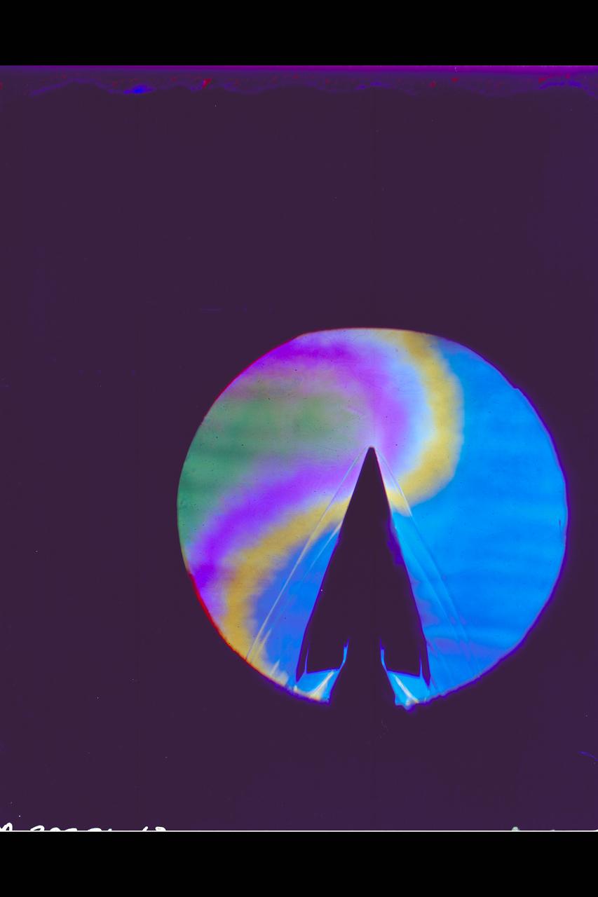
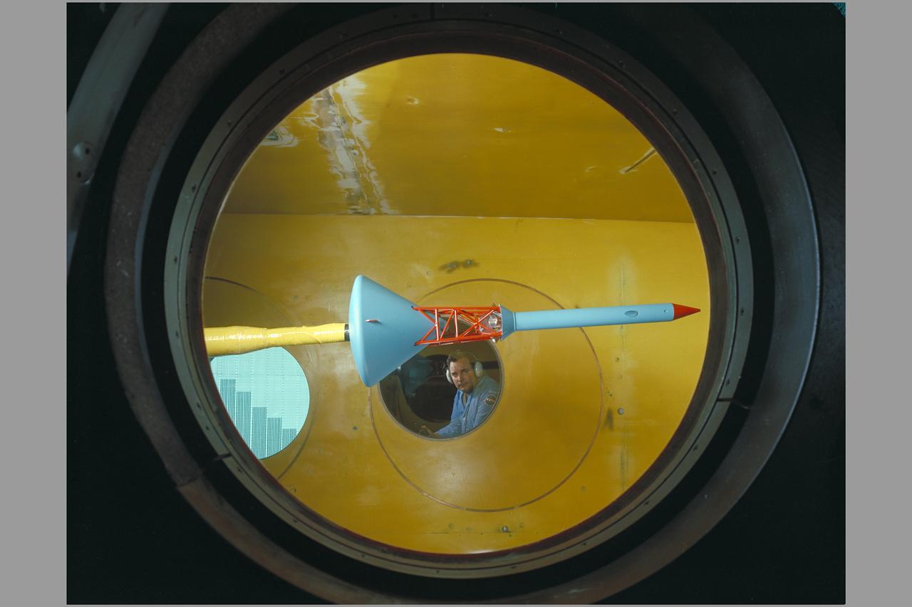
X-20 Dyna Soar on 624-A Titan III Booster: Schlieren
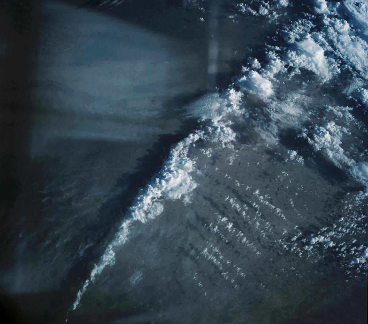
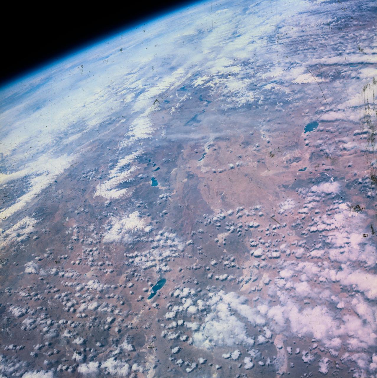
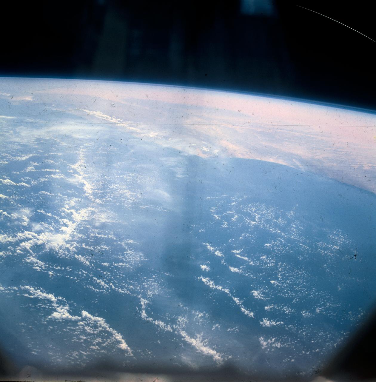
S63-06447 (15-16 May 1963) --- The Great Indian Desert, located west of New Delhi, India, as photographed from the Mercury-Atlas 9 (MA-9) capsule by astronaut L. Gordon Cooper Jr., during his 22-orbit MA-9 spaceflight. Photo credit: NASA
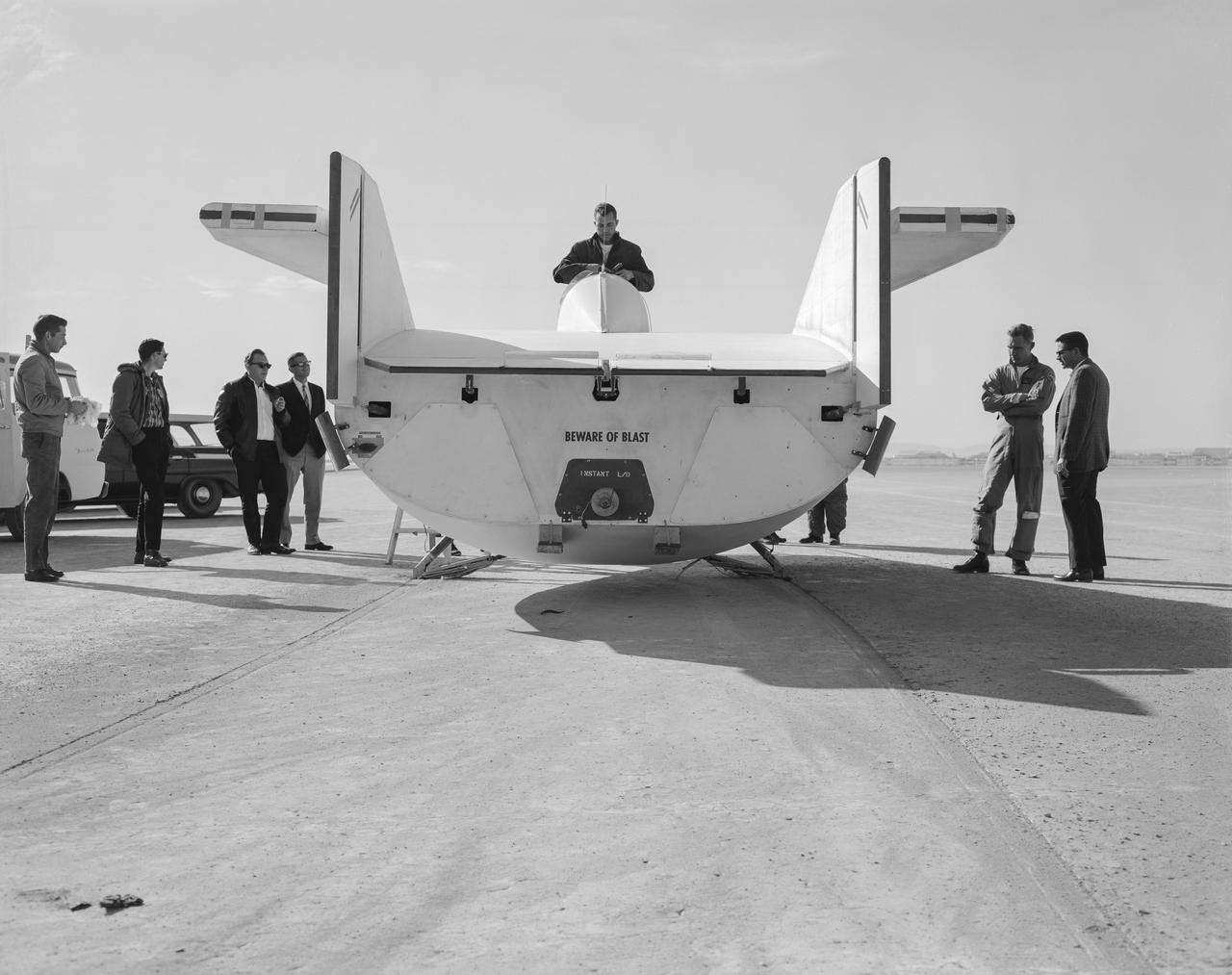
The M2-F1 following a hard landing on Rogers Dry Lake in 1963. It hit the lakebed so hard the rolling gear completely separated.

S63-00562 (February 1963) --- Portrait of astronaut groups 1 and 2. The original seven Mercury astronauts selected by NASA in April 1959, are seated (left to right): L. Gordon Cooper Jr., Virgil I. Grissom, M. Scott Carpenter, Water M. Schirra Jr., John H. Glenn Jr., Alan B. Shepard Jr., and Donald K. Slayton. The second group of NASA astronauts, which were named in September 1962, are standing (left to right): Edward H. White II, James A. McDivitt, John W. Young, Elliot M. See Jr., Charles Conrad Jr., Frank Borman, Neil A. Armstrong, Thomas P. Stafford, and James A. Lovell Jr. Photo credit: NASA or National Aeronautics and Space Administration
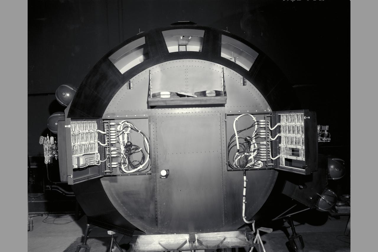
Apollo Capsule simulator
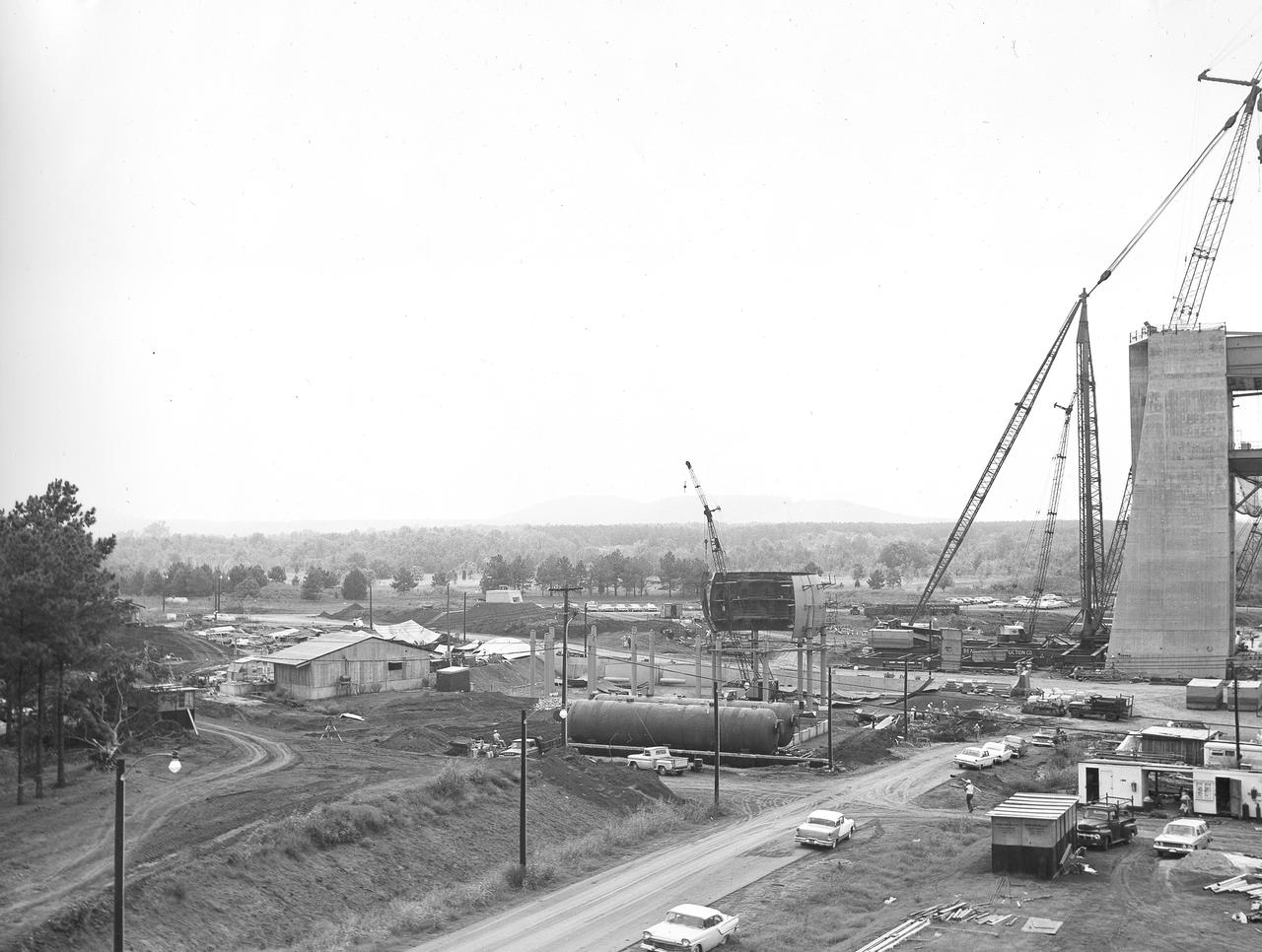
At its founding, the Marshall Space Flight Center (MSFC) inherited the Army’s Jupiter and Redstone test stands, but much larger facilities were needed for the giant stages of the Saturn V. From 1960 to 1964, the existing stands were remodeled and a sizable new test area was developed. The new comprehensive test complex for propulsion and structural dynamics was unique within the nation and the free world, and they remain so today because they were constructed with foresight to meet the future as well as on going needs. Construction of the S-IC Static test stand complex began in 1961 in the west test area of MSFC, and was completed in 1964. The S-IC static test stand was designed to develop and test the 138-ft long and 33-ft diameter Saturn V S-IC first stage, or booster stage, weighing in at 280,000 pounds. Required to hold down the brute force of a 7,500,000-pound thrust produced by 5 F-1 engines, the S-IC static test stand was designed and constructed with the strength of hundreds of tons of steel and 12,000,000 pounds of cement, planted down to bedrock 40 feet below ground level. The foundation walls, constructed with concrete and steel, are 4 feet thick. The base structure consists of four towers with 40-foot-thick walls extending upward 144 feet above ground level. The structure was topped by a crane with a 135-foot boom. With the boom in the upright position, the stand was given an overall height of 405 feet, placing it among the highest structures in Alabama at the time. In addition to the stand itself, related facilities were constructed during this time. In the center portion of this photograph, taken September 5, 1963, the spherical hydrogen storage tanks are being constructed. One of the massive tower legs of the S-IC test stand is visible to the far right.
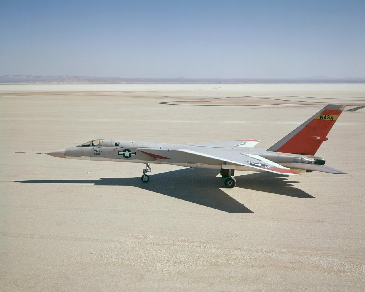
A North American Aviation A-5A Vigilante (Navy serial number 147858/NASA tail number 858) arrived from the Naval Air Test Center, Patuxent River, MD, on December 19, 1962, at the NASA Flight Research Center (now, Dryden Flight Research Center, Edwards, CA). The Center flew the A-5A in a year-long series of flights in support of the U.S. supersonic transport program. The Center flew the aircraft to determine the let-down and approach conditions of a supersonic transport flying into a dense air traffic network. With the completion of the research flights, the Center sent the A-5A back to the Navy on December 20, 1963.
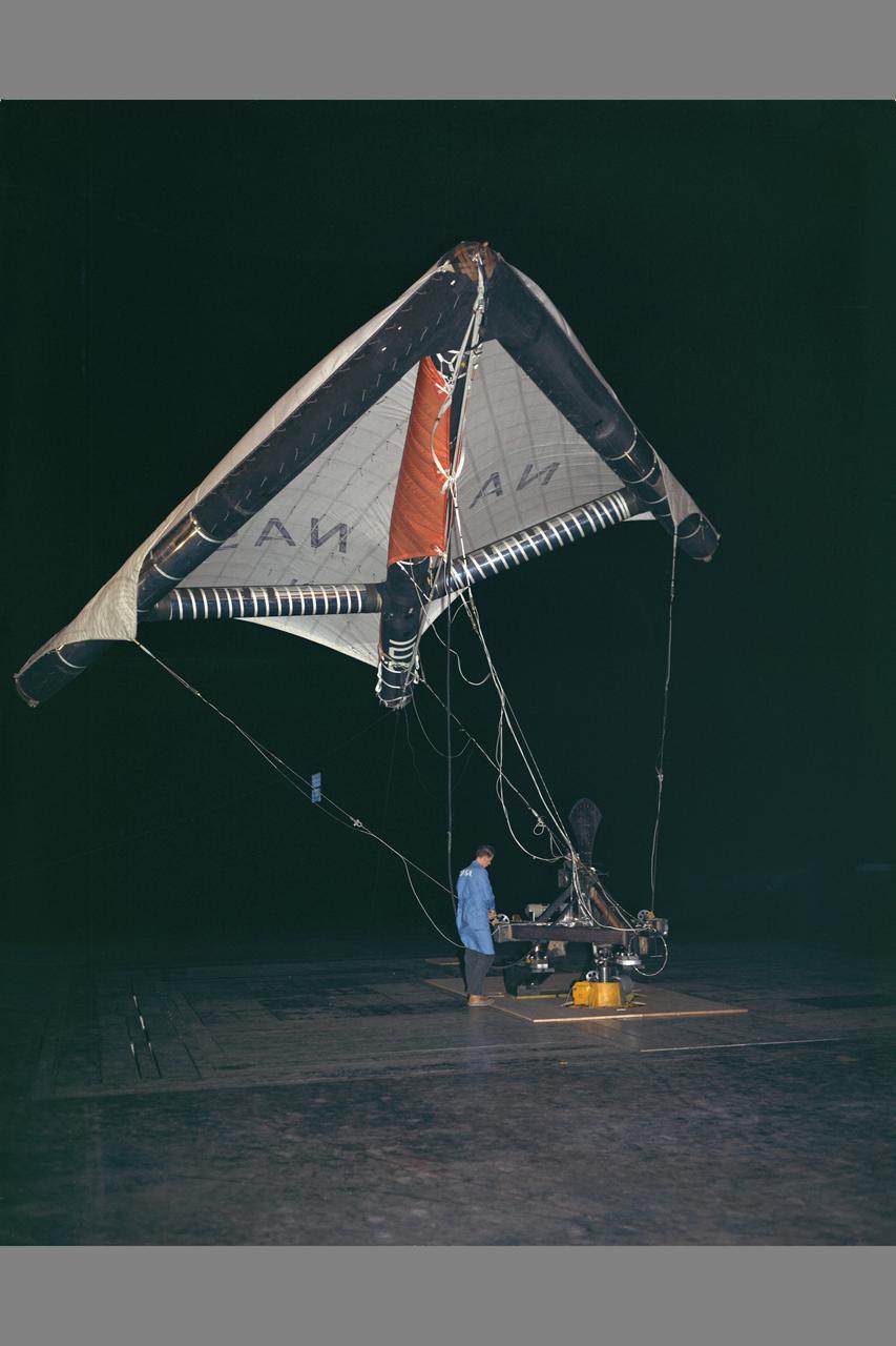
Paraglider Test in 40x80ft W.T.

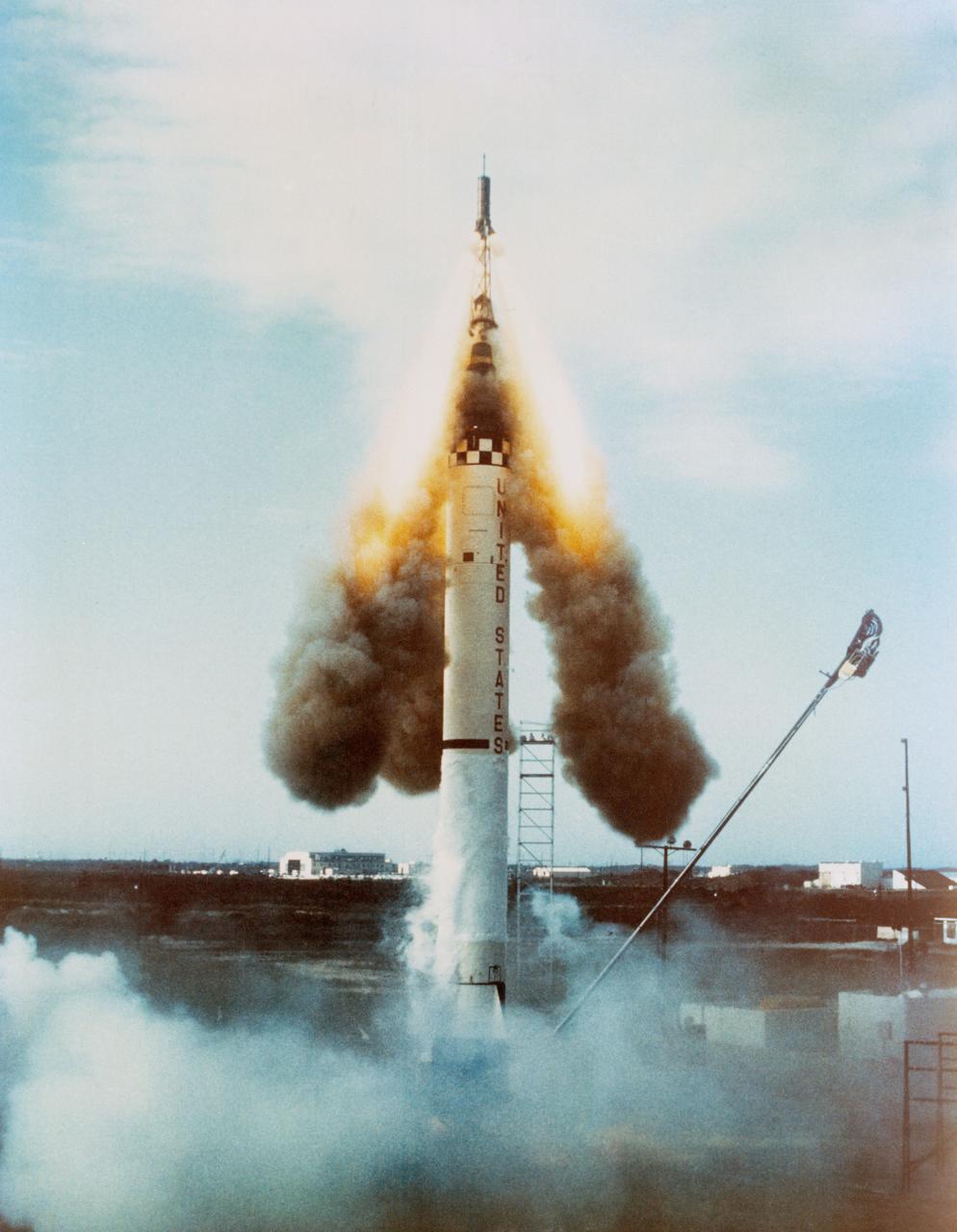
S63-02651 (21 July 1961) --- This is a ground-level view of the Mercury-Redstone (MR-4) launch of Virgil I. Grissom on July 21, 1961, from Cape Canaveral, Florida. Photo credit: NASA
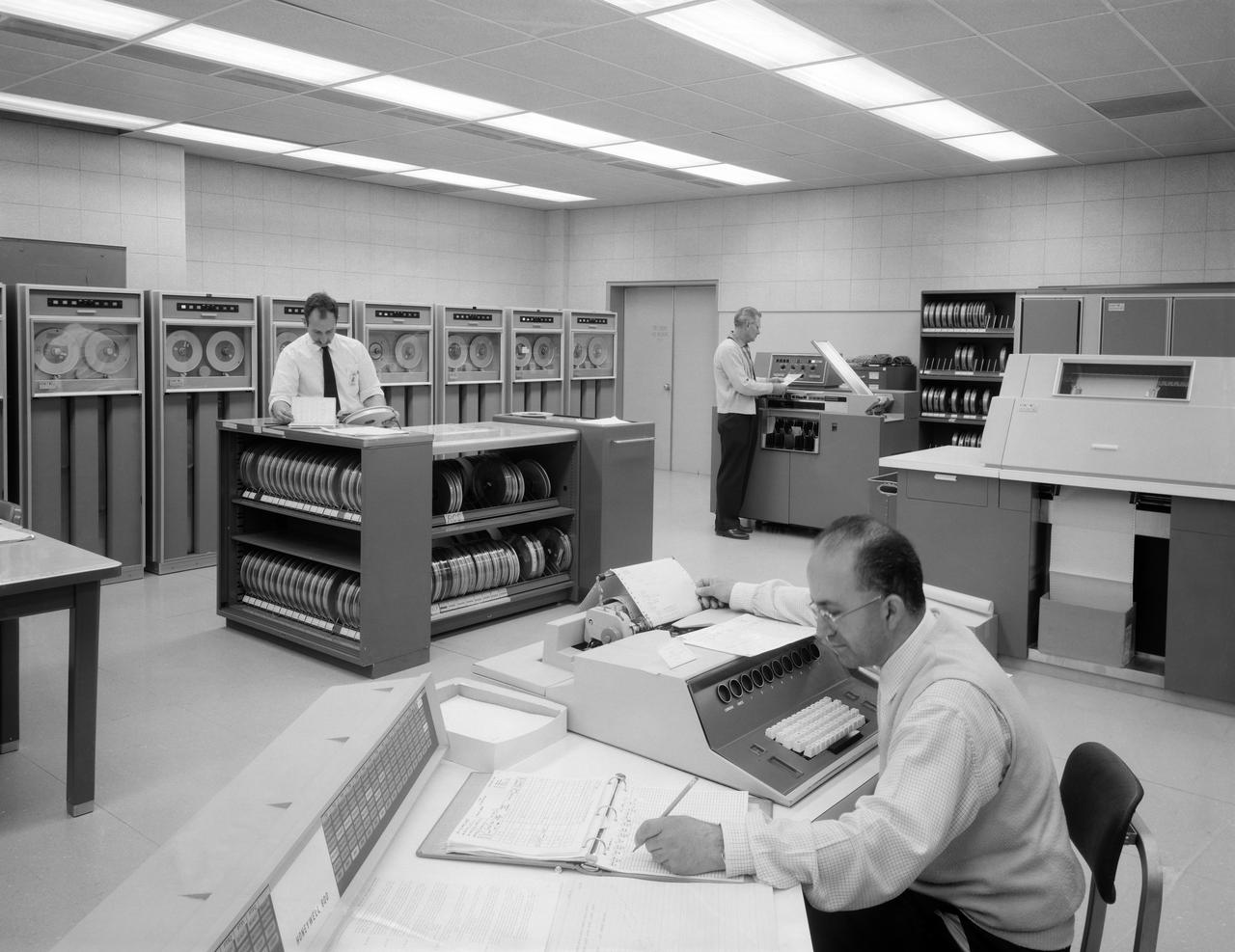
Honeywell H-800 Data Processing System at Ames Research Center
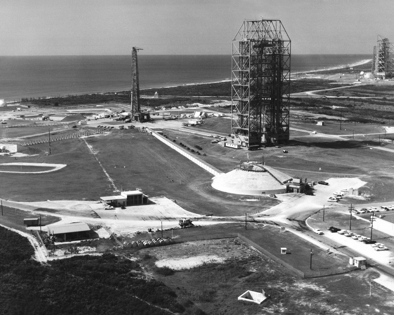
CAPE CANAVERAL, Fla. – Aerial, Launch Complex 34. Photo credit: NASA
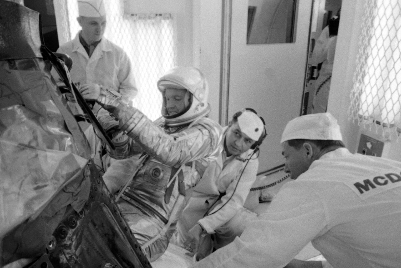
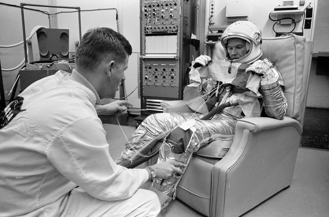
S63-03957 (1963) --- NASA and McDonnell Aircraft Corp. spacecraft technicians assist astronaut L. Gordon Cooper Jr. into his spacecraft prior to undergoing tests in the altitude chamber. These tests are used to determine the operating characteristcs of the overall environmental control system. Photo credit: NASA
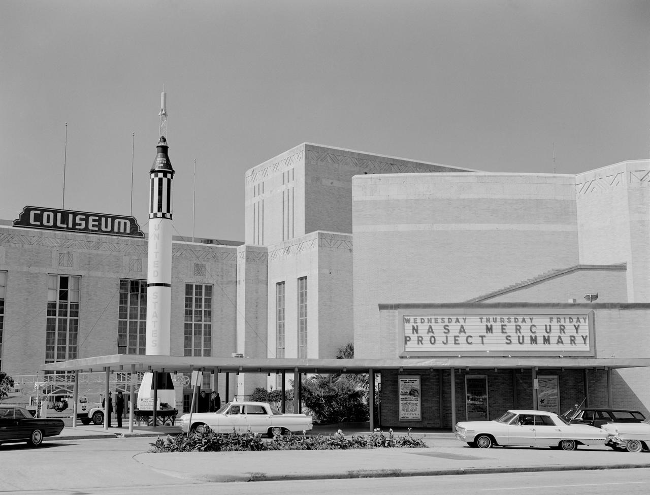
In October 1963, the Project Mercury Summary Conference was held in the Houston, TX, Coliseum. This series of 44 photos is documentation of that conference. A view of the Houston, TX, Coliseum, and parking area in front with a Mercury Redstone Rocket setup in the parking lot for display (S63-16451). A view of an Air Force Atlas Rocket, a Mercury Redstone Rocket, and a Mercury Spacecraft on a test booster on display in the front area of the Coliseum (S63-16452). A view an Air Force Atlas Rocket and a Mercury Redstone Rocket set up for display with the Houston City Hall in the background (S63- 16453). This view shows the Atlas Rocket, Mercury Redstone, and Mercury Test Rocket with the Houston, TX, Coliseum in the background (S63- 16454). A balcony view, from the audience right side, of the attendees looking at the stage (S63-16455). A view of the NASA Space Science Demonstration with equipment setup on a table, center stage and Space Science Specialist briefing the group as he pours Liquid Oxygen into a beaker (S63-16456). View of the audience from the balcony on the audience right showing the speakers lecturn on stage to the audience left (S63-16457). A view of attendees in the lobby. Bennet James, MSC Public Affairs Office is seen to the left of center (S63-16458). Another view of the attendees in the lobby (S63- 16459). In this view, Astronaut Neil Armstrong is seen writing as others look on (S63-16460). In this view of the attendees, Astronauts Buzz Aldrin and Walt Cunningham are seen in the center of the shot. The October Calendar of Events is visable in the background (S63-16461). Dr. Charles Berry is seen in this view to the right of center, seated in the audience (S63-16462). View of " Special Registration " and the five ladies working there (S63-16463). A view from behind the special registration table, of the attendees being registered (S63-16464). A view of a conference table with a panel seated. (R-L): Dr. Robert R. Gilruth, Hugh L. Dryden, Walter C. Williams, and an unidentified man (S63- 16465). A closeup of the panel at the table with Dr. Gilruth on the left (S63-16466). About the same shot as number S63-16462, Dr. Berry is seen in this shot as well (S63-16467). In this view the audio setup is seen. In the audience, (L-R): C. C. Kraft, Vernon E. (Buddy) Powell, Public Affairs Office (PAO); and, in the foreground mixing the audio is Art Tantillo; and, at the recorder is Doyle Hodges both of the audio people are contractors that work for PAO at MSC (S63-16468). In this view Maxime Faget is seen speaking at the lecturn (S63-16469). Unidentified person at the lecturn (S63-16470). In this view the motion picture cameras and personel are shown documenting the conference (S63-16471). A motion picture cameraman in the balcony is shown filming the audience during a break (S63- 16472). Family members enjoy an exhibit (S63-16473). A young person gets a boost to look in a Gemini Capsule on display (S63-16474). A young person looks at the Gemini Capsule on display (S63-16475). Dr. Robert R. Gilruth is seen at the conference table (S63-16476). Walt Williams is seen in this view at the conference table (S63-16477). Unidentified man sitting next to Walt Williams (S63-16478). (L-R): Seated at the conference table, Dr. Robert Gilruth, Hugh L. Dryden, and Walt Williams (S63- 16479). Group in lobby faces visable, (L-R): Walt Williams, unidentified person, Dr. Robert Gilruth, Congressman (S63-16480). Man in uniform at the lecturn (S63-16481). Astronaut Leroy Gordon Cooper at the lecturn (S63-16482). Astronaut Cooper at the lecturn with a picture on the screen with the title, " Astronaut Names for Spacecraft " (S63-16483). Dr. Gilruth at the lecturn (S63-16484). Walt Williams at the lecturn (S63-16485). Unidentified man at the lecturn (S63-16486). John H. Boynton addresses the Summary Conference (S63-16487). (L-R): Astronaut Leroy Gordon Cooper, Mrs. Cooper, Senator Cris Cole, and Mrs. Cole (S63- 16488). In this view in the lobby, Senator and Mrs. Cris Cole, with Astronaut Gordon Cooper standing near the heatshield, and Mrs. Cooper; next, on the right is a press photographer (S63-16489). (L-R): Astronaut L. Gordon Cooper and Mrs. Cooper, unidentified man, and Senator Walter Richter (S63-16490). (L-R): Eugene Horton, partially obscured, briefs a group on the Mercury Spacecraft, an unidentified person, Harold Ogden, a female senator, Senator Chris Cole, Mrs. Cole, an unidentified female, Senator Walter Richter, Jim Bower, and an unidentified female (S63-16491). In this view, Mrs. Jim Bates is seen in the center, and Senator Walter Richter to the right (S63- 16492). The next three (3) shots are 4X5 CN (S63-16493 - S63-16495). In this view a NASA Space Science Demonstration is seen (S63-16493). In this view a shot of the conference table is seen, and, (L-R): Dr. Robert R. Gilruth, Hugh L. Dryden, Mr. Walter Williams, and an unidentfied man (S63-16494 - S63-16495). HOUSTON, TX
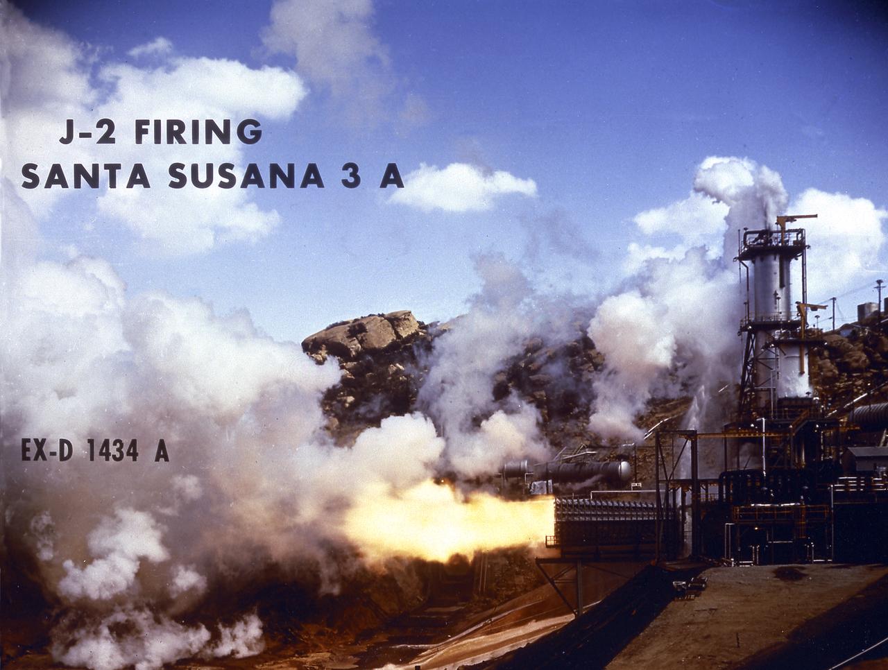
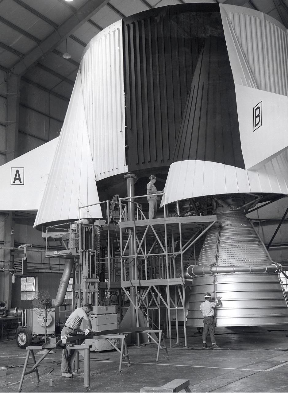
Smokeless flame juts from the diffuser of a unique vacuum chamber in which the upper stage rocket engine, the hydrogen fueled J-2, was tested at a simulated space altitude in excess of 60,000 feet. The smoke you see is actually steam. In operation, vacuum is established by injecting steam into the chamber and is maintained by the thrust of the engine firing through the diffuser. The engine was tested in this environment for start, stop, coast, restart, and full-duration operations. The chamber was located at Rocketdyne's Propulsion Field Laboratory, in the Santa Susana Mountains, near Canoga Park, California. The J-2 engine was developed by Rocketdyne for the Marshall Space Flight Center.
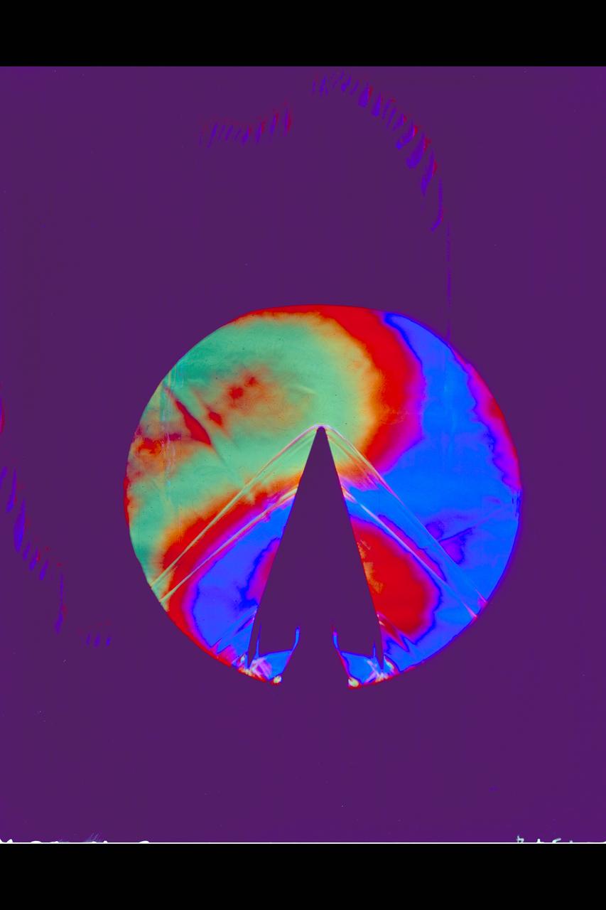
Schlieren of X-20 Dyna Soar mounted on 624-A Titan III Booster
S63-03986 (1963) --- Astronaut L. Gordon Cooper Jr., prime pilot for the Mercury-Atlas 9 (MA-9) mission, and General Dynamics pad technicians watch Atlas 130D being hoisted into place in the gantry at pad #14, Cape Canaveral, Florida. Photo credit: NASA
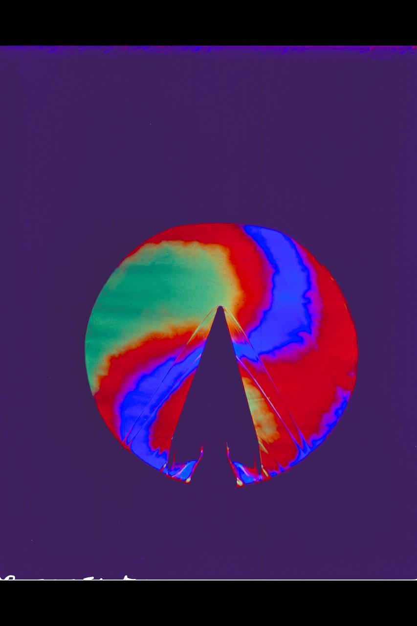
X-20 Dyna Soar on 624-A Titan III Booster: Schlieren
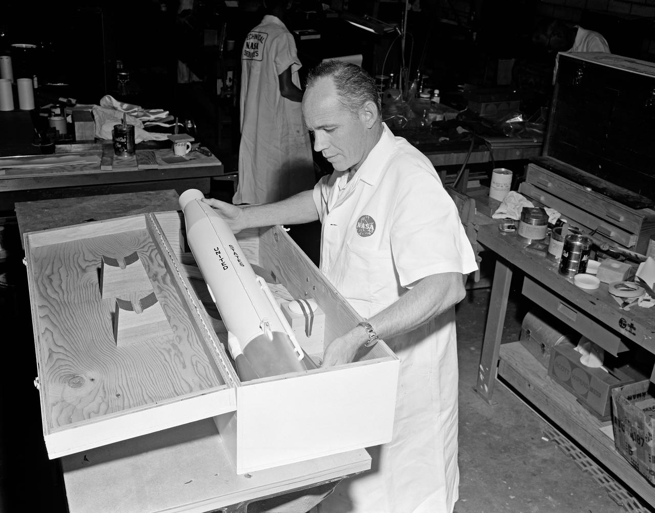
View of NASA Technical Services personnel packing model of rocket in the Canada Dry Bldg.
S63-03964 (1963) --- Al Rochford, Crew Systems, Manned Space Center, assists astronaut L. Gordon Cooper Jr., in checking his life vest, normally stowed in a pocket in the lower left leg. Photo credit: NASA
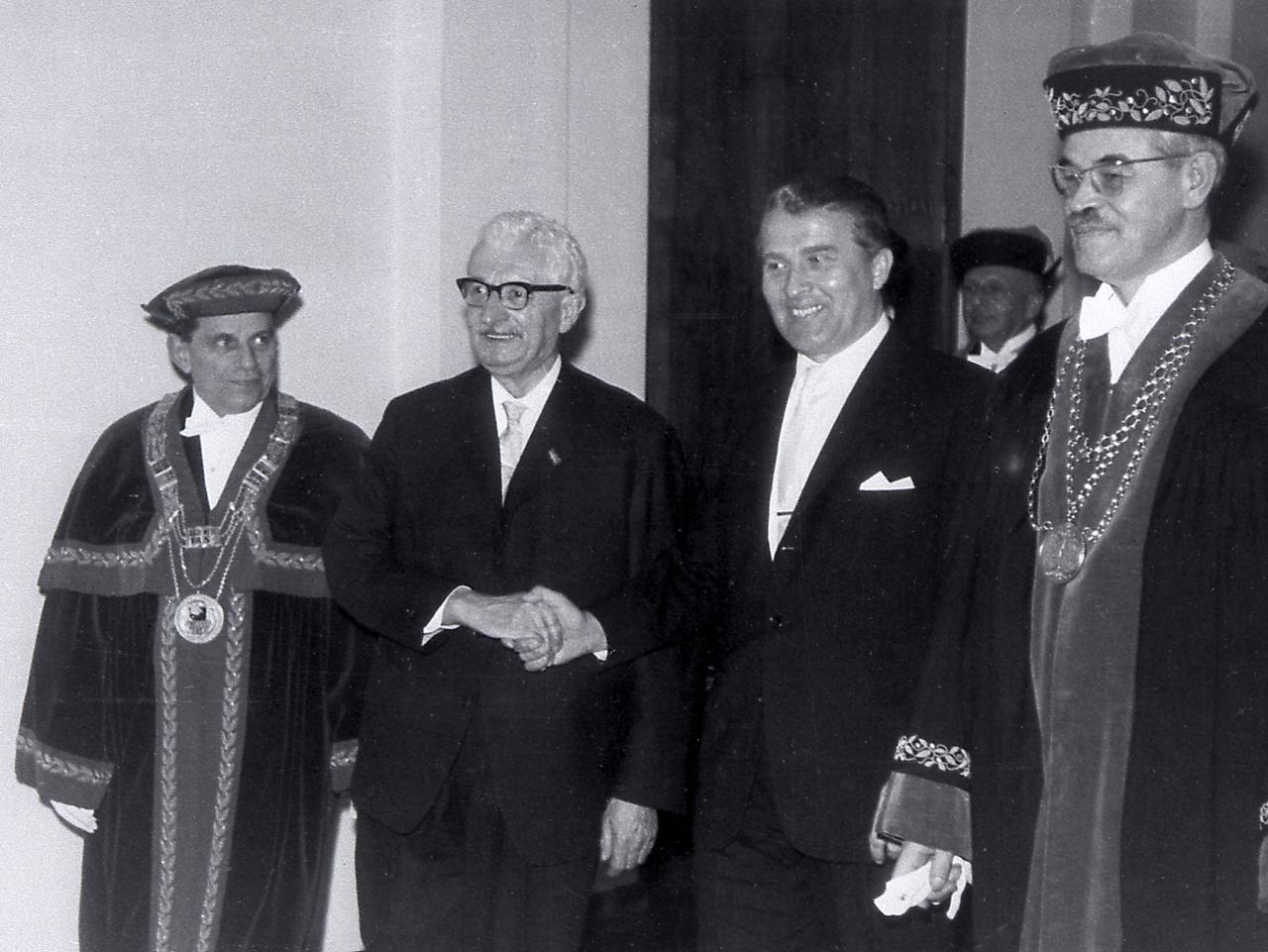
Dr. von Braun and Professor Hermann Oberth are honored by the Berlin Technical University. Both received honorary doctorates on January 8, 1963.
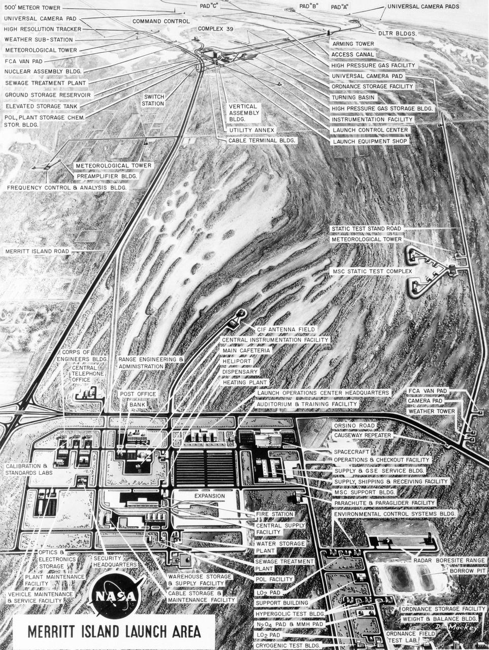
S63-23618 (December 1963) --- Aerial oblique artist concept of the Merritt Island Launch Complex, Merritt Island, Florida. Photo credit: NASA
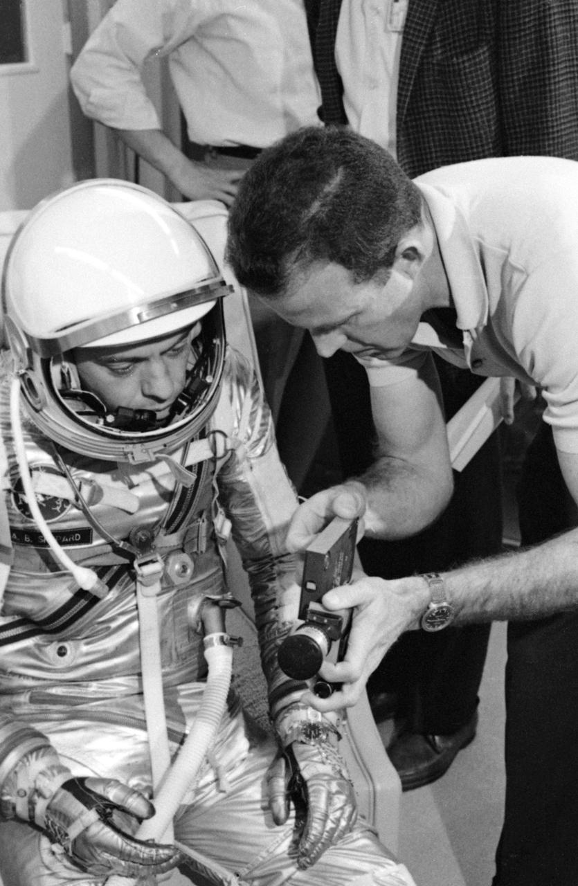
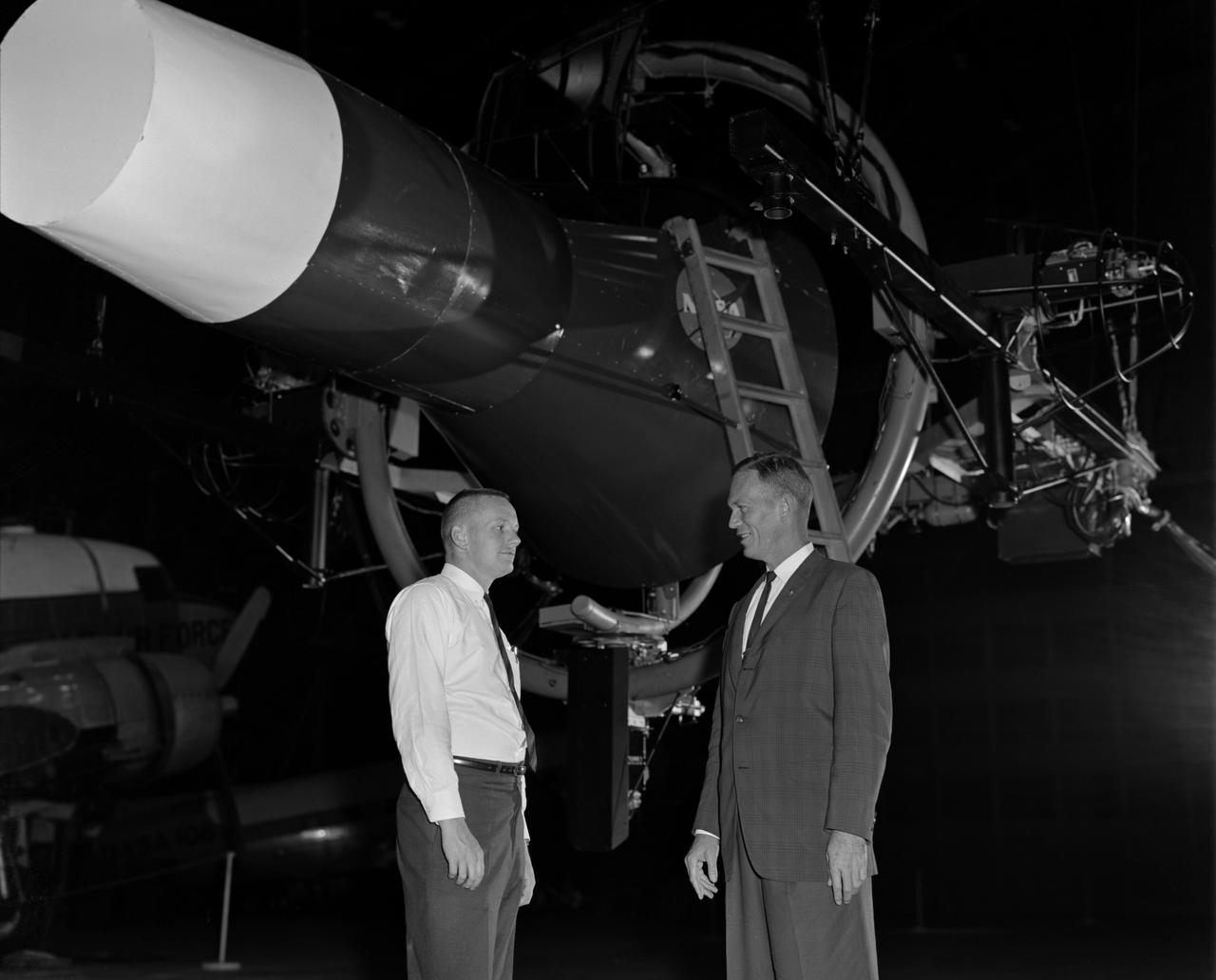
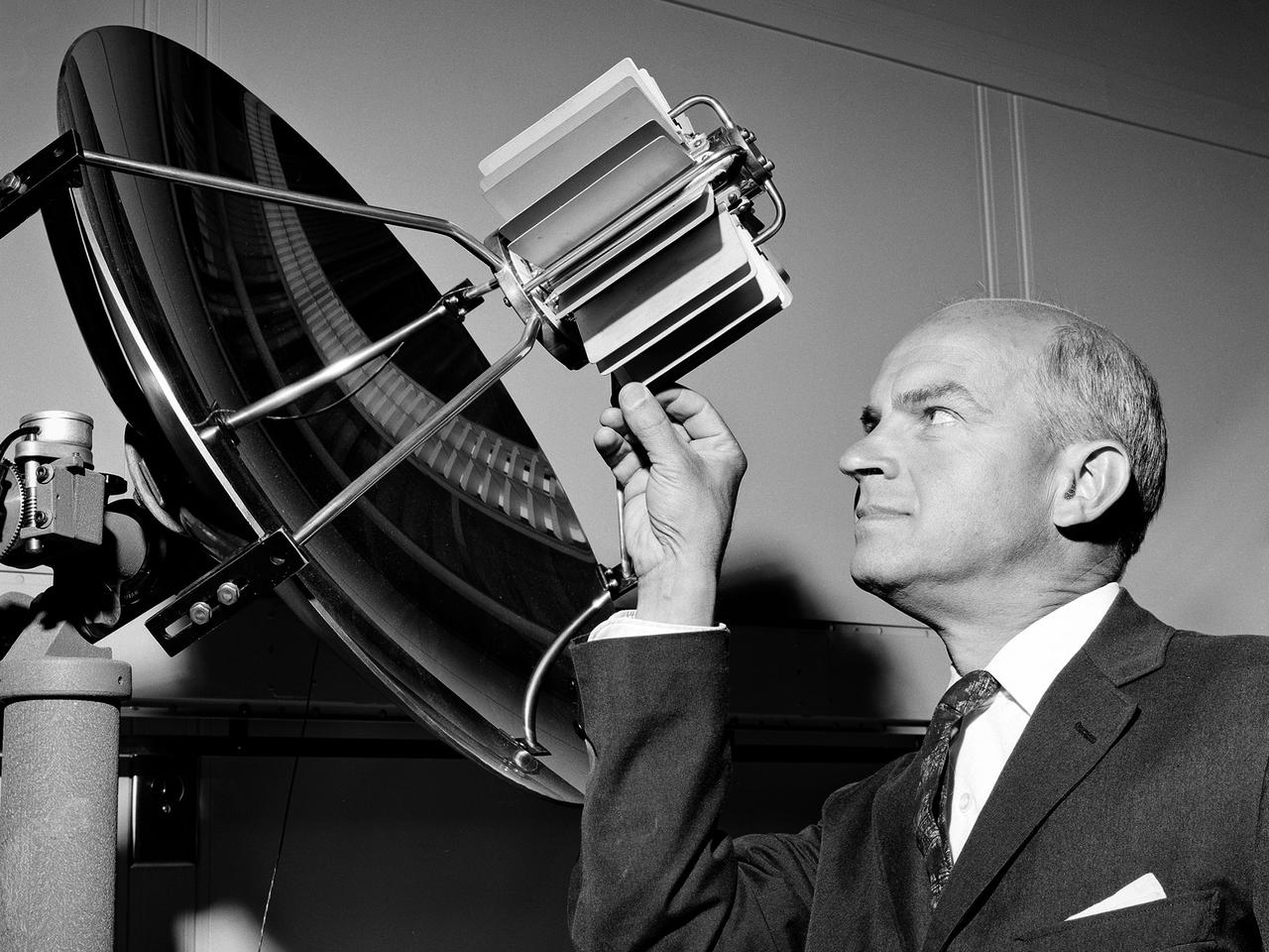
S63-03952 (1963) --- Astronaut L. Gordon Cooper Jr. explains the 16mm handheld spacecraft camera to his backup pilot astronaut Alan Shepard. The camera, designed by J.R. Hereford of McDonnell Aircraft Corp., will be used by Cooper during the Mercury-Atlas 9 (MA-9) mission to photograph experiments in space for M.I.T. and the Weather Bureau. Photo credit: NASA
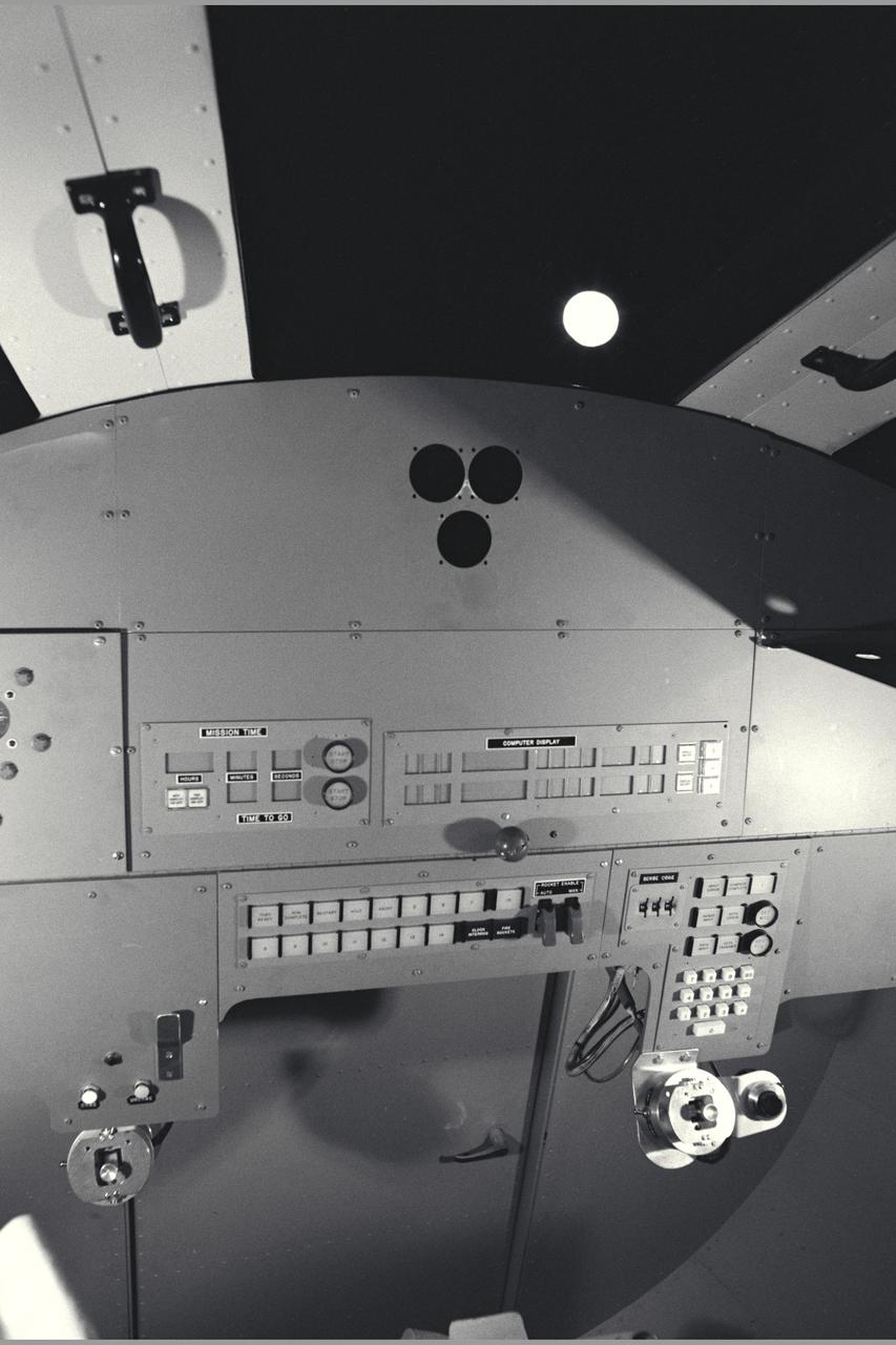
Apollo Capsule simulator
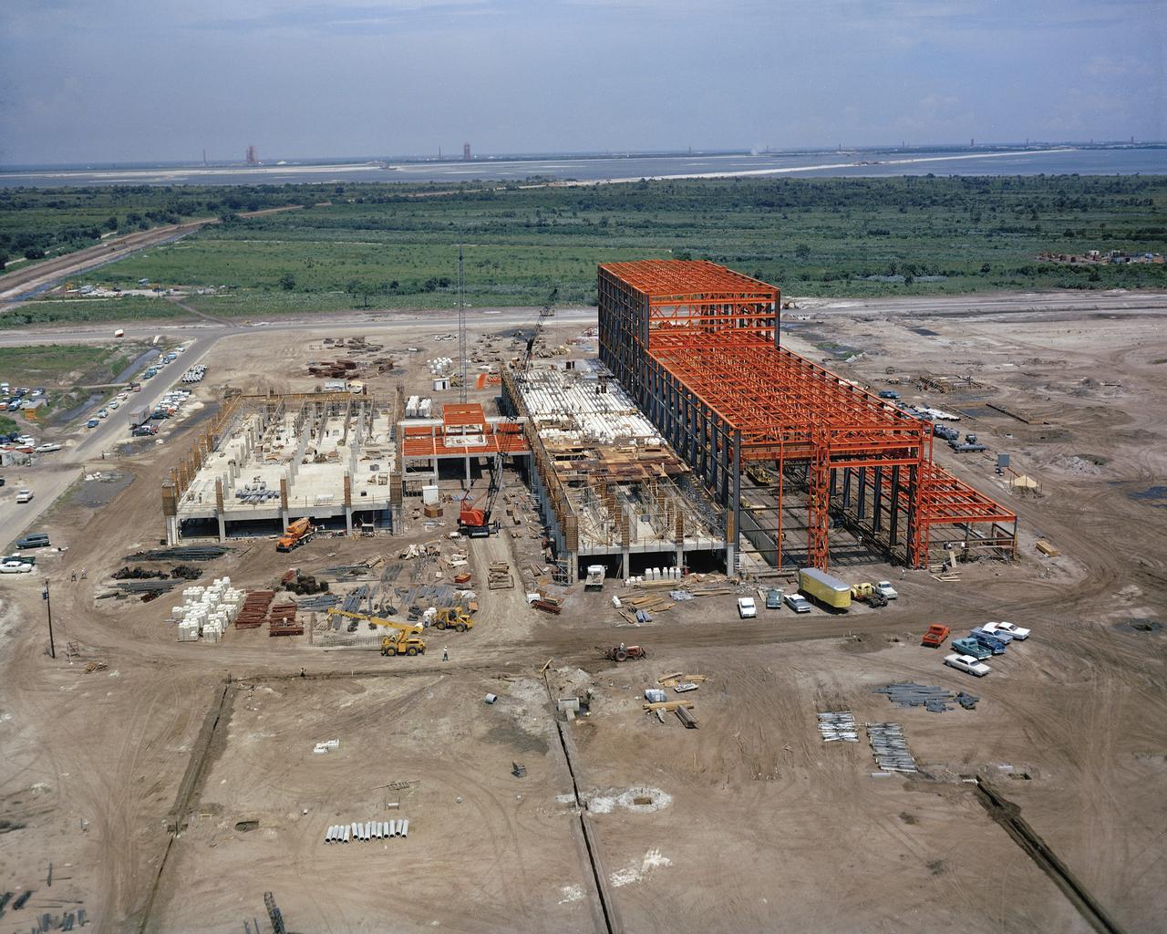
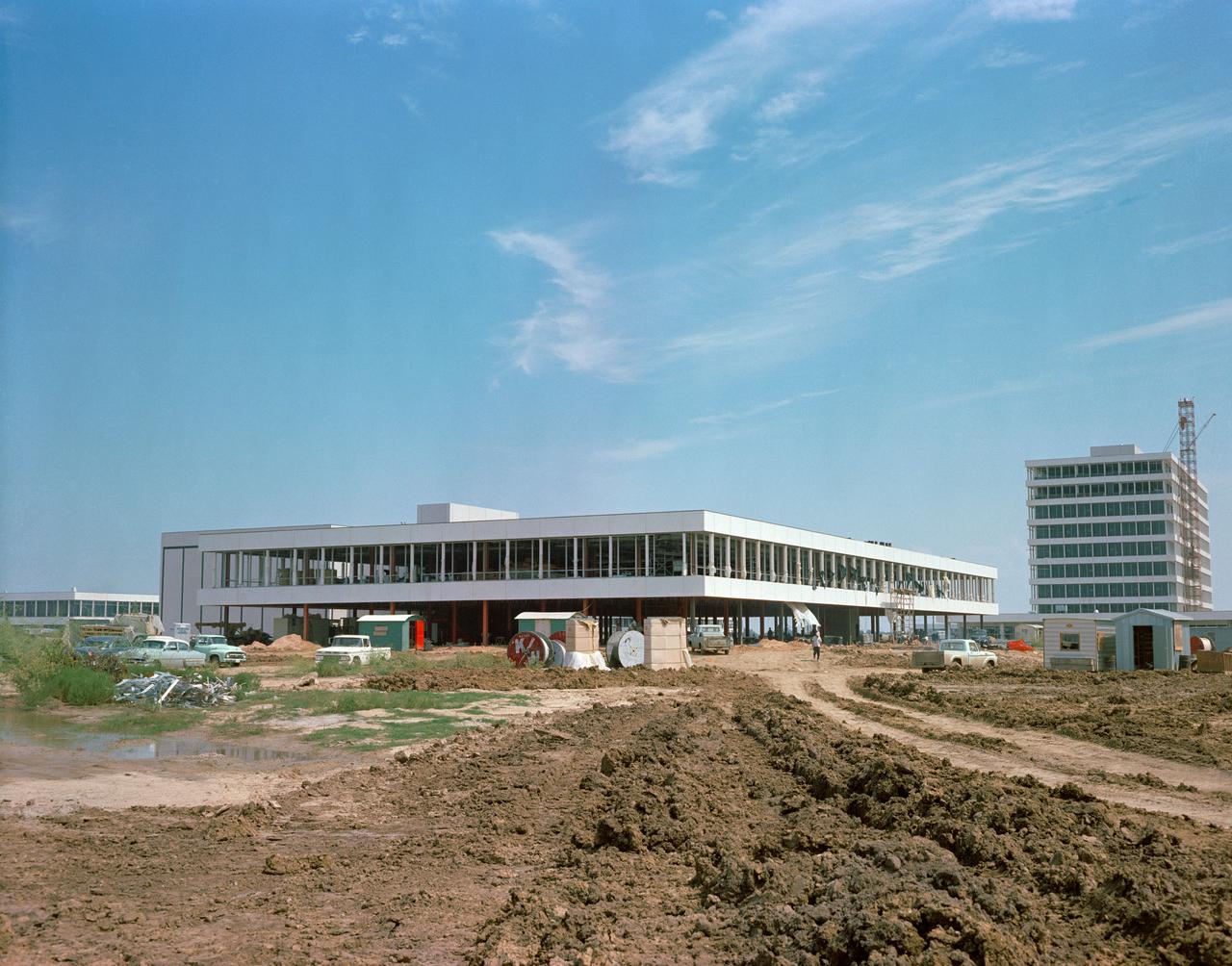
CAPE CANAVERAL Fla. -- This aerial view shows construction progress of the Manned Spacecraft Operations Building at NASA's Merritt Island Launch Annex. Photo Credit: NASA

S63-06445 (15-16 May 1963) --- View of the Himalaya Mountain Range in the India-Nepal-Tibet border area, as photographed from the Mercury-Atlas 9 capsule by astronaut L. Gordon Cooper Jr., during his 22-orbit MA-9 spaceflight. Photo credit: NASA
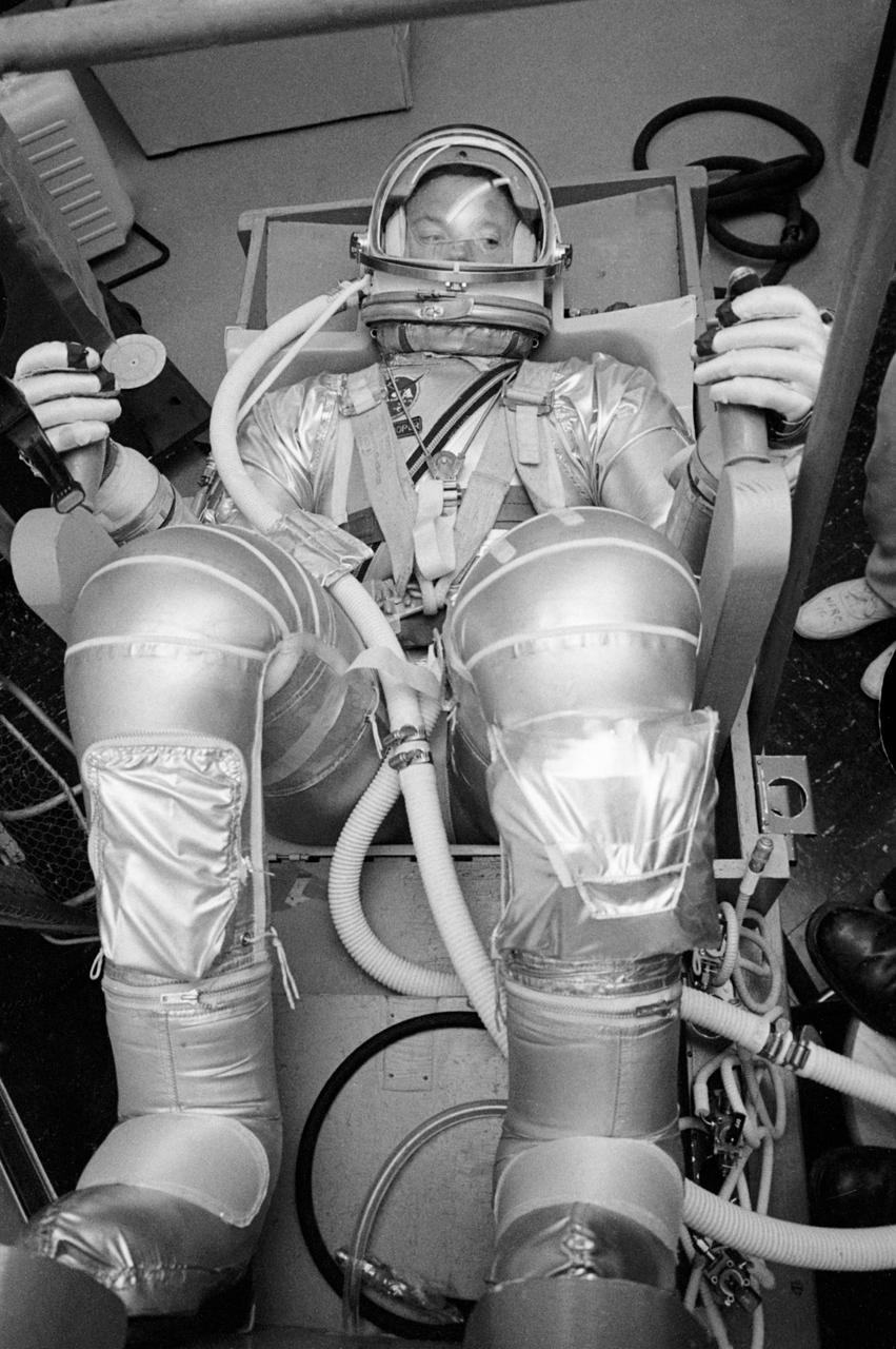
S63-03976 (1963) --- Astronaut L. Gordon Cooper Jr., prime pilot for the Mercury-Atlas 9 (MA-9) mission, undergoes suit pressurization tests. Photo credit: NASA
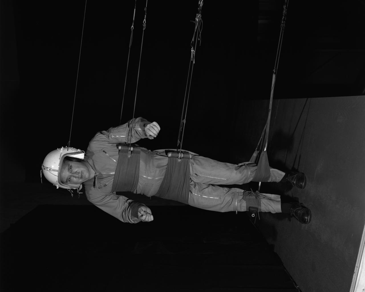
Reduced Gravity Walking Simulator located in the hangar at Langley Research Center. The initial version of this simulator was located inside the hangar. Later a larger version would be located at the Lunar Landing Facility. The purpose of this simulator was to study the subject while walking, jumping or running. Researchers conducted studies of various factors such as fatigue limit, energy expenditure, and speed of locomotion. A.W. Vigil wrote in his paper Discussion of Existing and Planned Simulators for Space Research, When the astronauts land on the moon they will be in an unfamiliar environment involving, particularly, a gravitational field only one-sixth as strong as on earth. A novel method of simulating lunar gravity has been developed and is supported by a puppet-type suspension system at the end of a long pendulum. A floor is provided at the proper angle so that one-sixth of the subject' s weight is supported by the floor with the remainder being supported by the suspension system. This simulator allows almost complete freedom in vertical translation and pitch and is considered to be a very realistic simulation of the lunar walking problem. For this problem this simulator suffers only slightly from the restrictions in lateral movement it puts on the test subject. This is not considered a strong disadvantage for ordinary walking problems since most of the motions do, in fact, occur in the vertical plane. However, this simulation technique would be severely restrictive if applied to the study of the extra-vehicular locomotion problem, for example, because in this situation complete six degrees of freedom are rather necessary. This technique, in effect, automatically introduces a two-axis attitude stabilization system into the problem. The technique could, however, be used in preliminary studies of extra-vehicular locomotion where, for example, it might be assumed that one axis of the attitude control system on the astronaut maneuvering unit may have failed. -- Published in James R. Hansen, Spaceflight Revolution: NASA Langley Research Center From Sputnik to Apollo, NASA SP-4308, p. 377 A.W. Vigil, Discussion of Existing and Planned Simulators for Space Research, Paper presented at Conference on the Role of Simulation in Space Technology, Blacksburg, VA, August 17-21, 1964.
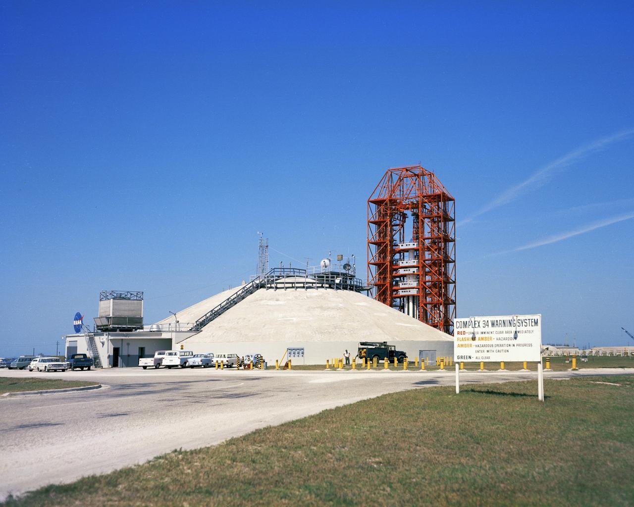
CAPE CANAVERAL, Fla. – Launch Pad 34 exterior, blockhouse and gantry. Photo credit: NASA
S63-07135 (16 May 1963) --- This was the Nation?s sixth manned orbital space flight, and the ?Faith 7? spacecraft was piloted by astronaut L. Gordon Cooper Jr. The launch was originally scheduled for May 14, 1963, but due to a malfunction in the radar tracking system at Bermuda. The launch was ?scrubbed? 12 minutes before countdown would have been completed. At midnight, May 15, 1963, countdown was resumed and liftoff occurred at 8:04 a.m. (EST), May 16, 1963. Astronaut L. Gordon Cooper Jr., completed a total of 22.9 orbits and spent 34 hours, 20 minutes in space flight. The launch and recovery was highly successful and was the last of the Mercury flights.
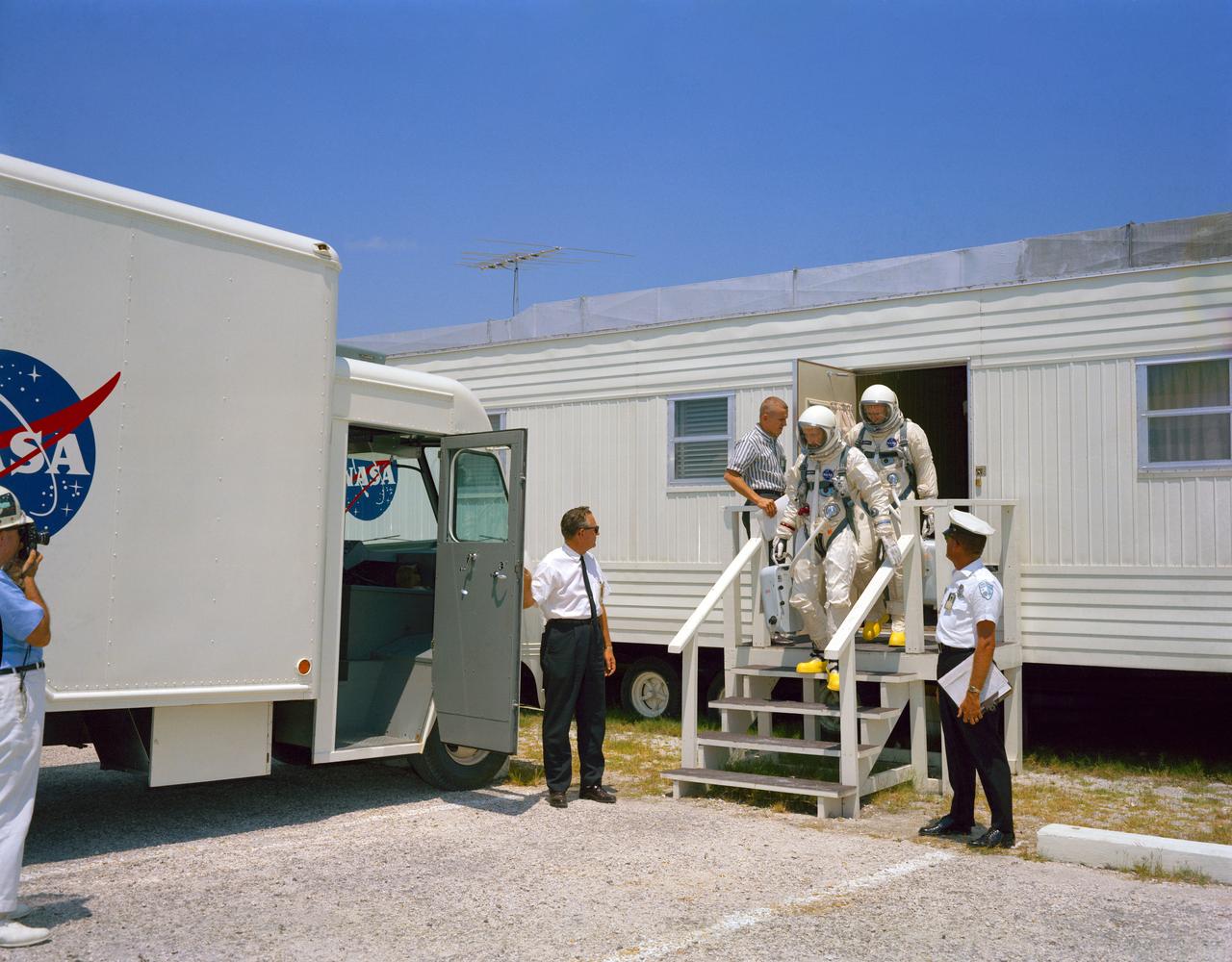
Astronauts Edward and James A. McDivitt are shown as they emerge from the suiting trailer located at Launch Complex 16. They are following in a Wet Mock Simulation Launch as a training exercise for GT-4. CAPE KENNEDY, FL B&W
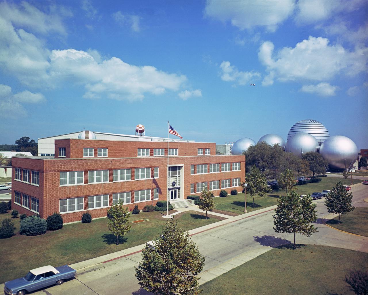
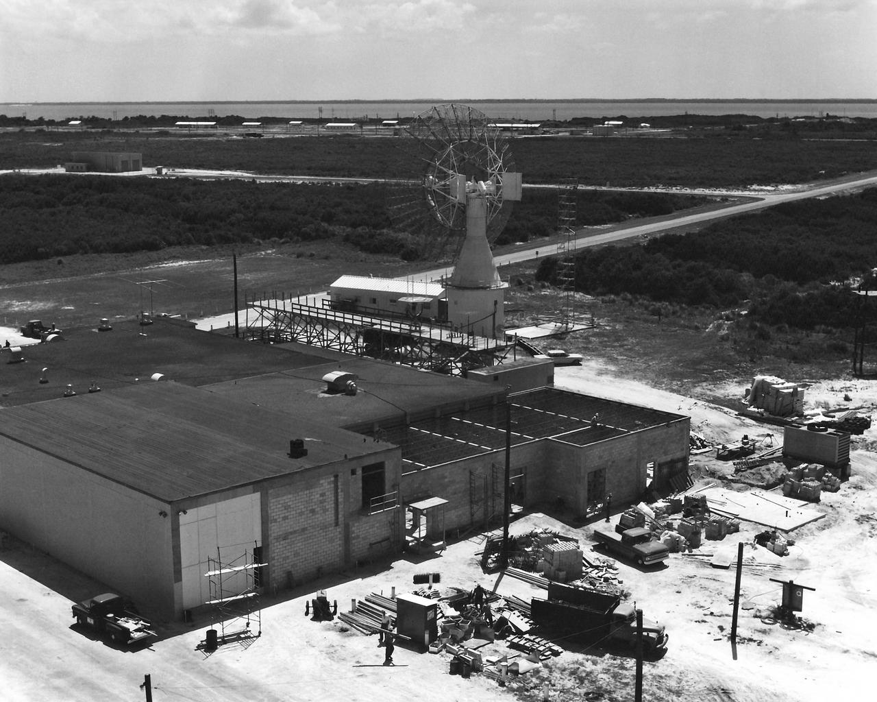
Headquarters building and spheres at Gas Dynamics. DAO Section. Scanned on 4/23/2018.
Astronaut Neil Armstrong (left) was one of 14 astronauts, 8 NASA test pilots, and 2 McDonnell test pilots who took part in simulator studies. Armstrong was the first astronaut to participate (November 6, 1963). A.W. Vogeley described the simulator in his paper "Discussion of Existing and Planned Simulators For Space Research," "Many of the astronauts have flown this simulator in support of the Gemini studies and they, without exception, appreciated the realism of the visual scene. The simulator has also been used in the development of pilot techniques to handle certain jet malfunctions in order that aborts could be avoided. In these situations large attitude changes are sometimes necessary and the false motion cues that were generated due to earth gravity were somewhat objectionable; however, the pilots were readily able to overlook these false motion cues in favor of the visual realism." Roy F. Brissenden, noted in his paper "Initial Operations with Langley's Rendezvous Docking Facility," "The basic Gemini control studies developed the necessary techniques and demonstrated the ability of human pilots to perform final space docking with the specified Gemini-Agena systems using only visual references. ... Results... showed that trained astronauts can effect the docking with direct acceleration control and even with jet malfunctions as long as good visual conditions exist.... Probably more important than data results was the early confidence that the astronauts themselves gained in their ability to perform the maneuver in the ultimate flight mission." Francis B. Smith, noted in his paper "Simulators for Manned Space Research," "Some major areas of interest in these flights were fuel requirements, docking accuracies, the development of visual aids to assist alignment of the vehicles, and investigation of alternate control techniques with partial failure modes. However, the familiarization and confidence developed by the astronaut through flying and safely docking the simulator during these tests was one of the major contributions. For example, it was found that fuel used in docking from 200 feet typically dropped from about 20 pounds to 7 pounds after an astronaut had made a few training flights." -- Published in Barton C. Hacker and James M. Grimwood, On the Shoulders of Titans: A History of Project Gemini, NASA SP-4203; A.W. Vogeley, "Discussion of Existing and Planned Simulators For Space Research," Paper presented at the Conference on the Role of Simulation in Space Technology, August 17-21, 1964; Roy F. Brissenden, "Initial Operations with Langley's Rendezvous Docking Facility," Langley Working Paper, LWP-21, 1964; Francis B. Smith, "Simulators for Manned Space Research," Paper presented at the 1966 IEEE International convention, March 21-25, 1966.
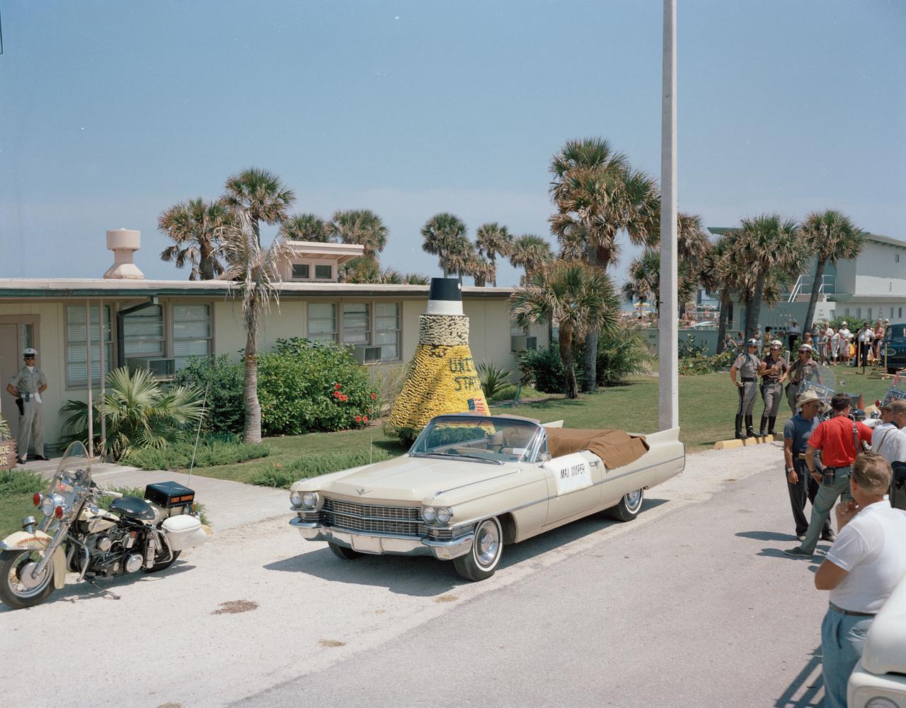
S63-07642 (1963) --- Arrival of astronaut L. Gordon Cooper Jr. at Patrick Air Force Base for parade in his honor. Photo credit: NASA
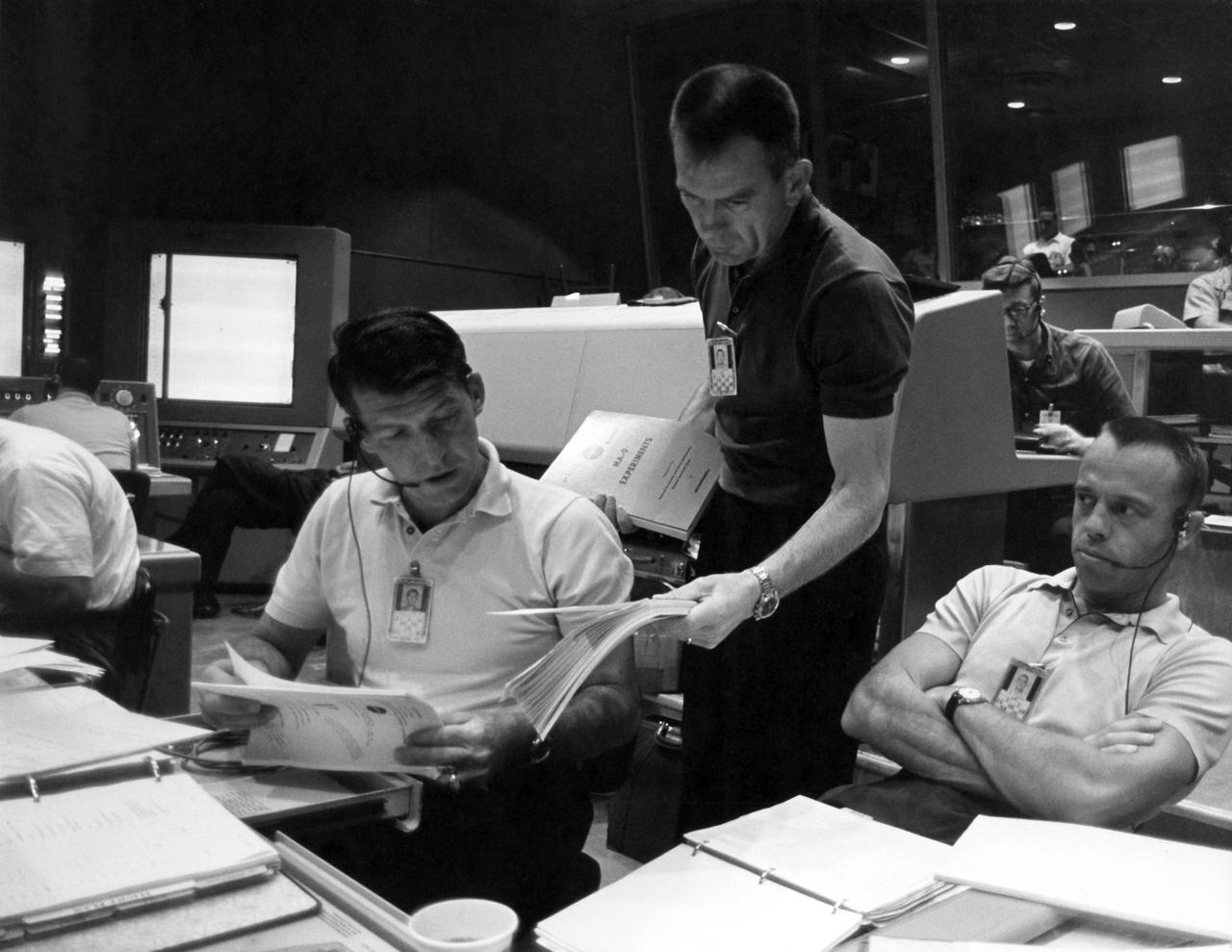
CAPE CANAVERAL, Fla. - Inside Mercury Mission Control, astronaut Deke Slayton left discusses a point with Christopher Kraft, Mercury's flight director, during preparations for astronaut Gordon Cooper's Faith 7 launch, which took place on May 15, 1963. The Mercury Mission Control Center in Florida played a key role in the United States' early spaceflight program. Located at Cape Canaveral Air Force Station, the original part of the building was constructed between 1956 and 1958, with additions in 1959 and 1963. The facility officially was transferred to NASA on Dec. 26, 1963, and served as mission control during all the Project Mercury missions, as well as the first three flights of the Gemini Program, when it was renamed Mission Control Center. With its operational days behind, on June 1, 1967, the Mission Control Center became a stop on the public tour of NASA facilities until the mid-90s. In 1999, much of the equipment and furnishings from the Flight Control Area were moved to the Kennedy Space Center Visitor Complex where they became part of the exhibit there. The building was demolished in spring 2010. Photo credit: NASA
Astronaut Alan Shepard (right) was one of 14 astronauts, 8 NASA test pilots, and 2 McDonnell test pilots who took part in simulator studies. Shepard flew the simulator on November 14, 1963. A.W. Vogeley wrote: "Many of the astronauts have flown this simulator in support of the Gemini studies and they, without exception, appreciated the realism of the visual scene. The simulator has also been used in the development of pilot techniques to handle certain jet malfunctions in order that aborts could be avoided. In these situations large attitude changes are sometimes necessary and the false motion cues that were generated due to earth gravity were somewhat objectionable; however, the pilots were readily able to overlook these false motion cues in favor of the visual realism." Roy F. Brissenden noted that: "The basic Gemini control studies developed the necessary techniques and demonstrated the ability of human pilots to perform final space docking with the specified Gemini-Agena systems using only visual references. ... Results... showed that trained astronauts can effect the docking with direct acceleration control and even with jet malfunctions as long as good visual conditions exist.... Probably more important than data results was the early confidence that the astronauts themselves gained in their ability to perform the maneuver in the ultimate flight mission." Shepard commented: "I had the feeling tonight - a couple of times - that I was actually doing the space mission instead of the simulation. As I said before, I think it is a very good simulation." Shepard also commented on piloting techniques. Most astronauts arrived at this same preferred technique: Shepard: "I believe I have developed the preferred technique for these conditions and the technique appeared to me to be best was to come in slightly above the target so that I was able to use the longitudinal marks on the body of the target as a reference, particularly for a lateral translation and, of course, I used the foreshortening effect for a vertical translation, and this appeared to give me the best results. By that I mean the least number of control motions and the lowest fuel usage and the best end techniques, or the best end conditions, I should say." Engineer: "When you started to run you didn't start thrusting immediately I don't believe. It looked like you started working on your attitudes, then started closing in." Shepard: "That is correct. I did that because I felt that I wanted to get the X-axis translation in the most effective vector and for minimum fuel usage that wouldn't introduce any other lateral or vertical offsets that did not already exist." -- Published in Barton C. Hacker and James M. Grimwood, On the Shoulders of Titans: A History of Project Gemini, NASA SP-4203; A.W. Vogeley, "Discussion of Existing and Planned Simulators For Space Research," Paper presented at the Conference on the Role of Simulation in Space Technology, August 17-21, 1964; Roy F. Brissenden, "Initial Operations with Langley's Rendezvous Docking Facility," Langley Working Paper, LWP-21, 1964.
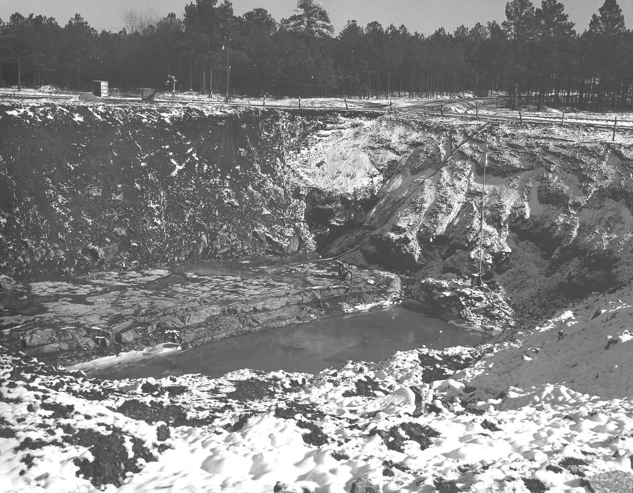
At its founding, the Marshall Space Flight Center (MSFC) inherited the Army’s Jupiter and Redstone test stands, but much larger facilities were needed for the giant stages of the Saturn V. From 1960 to 1964, the existing stands were remodeled and a sizable new test area was developed. The new comprehensive test complex for propulsion and structural dynamics was unique within the nation and the free world, and they remain so today because they were constructed with foresight to meet the future as well as on going needs. Construction of the S-IC Static test stand complex began in 1961 in the west test area of MSFC, and was completed in 1964. The S-IC static test stand was designed to develop and test the 138-ft long and 33-ft diameter Saturn V S-IC first stage, or booster stage, weighing in at 280,000 pounds. Required to hold down the brute force of a 7,500,000-pound thrust produced by 5 F-1 engines, the S-IC static test stand was designed and constructed with the strength of hundreds of tons of steel and 12,000,000 pounds of cement, planted down to bedrock 40 feet below ground level. The foundation walls, constructed with concrete and steel, are 4 feet thick. The base structure consists of four towers with 40-foot-thick walls extending upward 144 feet above ground level. The structure was topped by a crane with a 135-foot boom. With the boom in the upright position, the stand was given an overall height of 405 feet, placing it among the highest structures in Alabama at the time. In addition to the S-IC test stand, related facilities were constructed during this time frame. Built just north of the massive S-IC test stand was the F-1 Engine test stand. The F-1 test stand is a vertical engine firing test stand, 239 feet in elevation and 4,600 square feet in area at the base, and was designed to assist in the development of the F-1 Engine. Capability was provided for static firing of 1.5 million pounds of thrust using liquid oxygen and kerosene. Like the S-IC stand, the foundation of the F-1 stand is keyed into the bedrock approximately 40 feet below grade. This photo, taken January 14, 1963 depicts the F-1 test stand site with hoses pumping excess water from the site.
S63-06444 (15-16 May 1963) --- Tibet-Kashmir, looking northwest, as photographed from the Mercury-Atlas 9 (MA-9) capsule by astronaut L. Gordon Cooper Jr. during his 22-orbit MA-9 spaceflight. Lake Ch'in-Tzu-Hu is at upper right, Lake Yen-K'o-Ling-Ts is at lower left center. The Korakaram Range is at upper center portion of the picture. Photo credit: NASA
At its founding, the Marshall Space Flight Center (MSFC) inherited the Army’s Jupiter and Redstone test stands, but much larger facilities were needed for the giant stages of the Saturn V. From 1960 to 1964, the existing stands were remodeled and a sizable new test area was developed. The new comprehensive test complex for propulsion and structural dynamics was unique within the nation and the free world, and they remain so today because they were constructed with foresight to meet the future as well as on going needs. Construction of the S-IC Static test stand complex began in 1961 in the west test area of MSFC, and was completed in 1964. The S-IC static test stand was designed to develop and test the 138-ft long and 33-ft diameter Saturn V S-IC first stage, or booster stage, weighing in at 280,000 pounds. Required to hold down the brute force of a 7,500,000-pound thrust produced by 5 F-1 engines, the S-IC static test stand was designed and constructed with the strength of hundreds of tons of steel and 12,000,000 pounds of cement, planted down to bedrock 40 feet below ground level. The foundation walls, constructed with concrete and steel, are 4 feet thick. The base structure consists of four towers with 40-foot-thick walls extending upward 144 feet above ground level. The structure was topped by a crane with a 135-foot boom. With the boom in the upright position, the stand was given an overall height of 405 feet, placing it among the highest structures in Alabama at the time. North of the massive S-IC test stand, the F-1 Engine test stand was built. Designed to assist in the development of the F-1 Engine, the F-1 test stand is a vertical engine firing test stand, 239 feet in elevation and 4,600 square feet in area at the base. Capability was provided for static firing of 1.5 million pounds of thrust using liquid oxygen and kerosene. Like the S-IC stand, the foundation of the F-1 stand is keyed into the bedrock approximately 40 feet below grade. This photo, taken April 4, 1963 depicts the construction of the F-1 test stand foundation walls.
This photograph depicts Marshall Space Flight Center employees, James Reagin, machinist (top); Floyd McGinnis, machinist; and Ernest Davis, experimental test mechanic (foreground), working on a mock up of the S-IC thrust structure. The S-IC stage is the first stage, or booster, of the 364-foot long Saturn V rocket that ultimately took astronauts to the Moon. The S-IC stage, burned over 15 tons of propellant per second during its 2.5 minutes of operation to take the vehicle to a height of about 36 miles and to a speed of about 6,000 miles per hour. The stage was 138 feet long and 33 feet in diameter. Operating at maximum power, all five of the engines produced 7,500,000 pounds of thrust.
S63-03975 (1963) --- Astronaut L. Gordon Cooper Jr., prime pilot for the Mercury-Atlas 9 (MA-9) mission, is pictured prior to entering the Mercury spacecraft for a series of simulated flight tests. During these tests NASA doctors, engineers and technicians monitor Cooper's performance. Photo credit: NASA
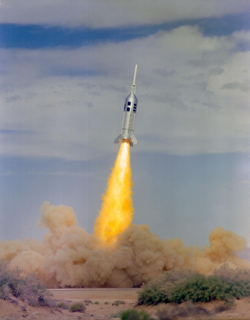
S63-15701 (28 August 1963) --- All seven motors of Little Joe II, ignited simultaneously at launch, with a total thrust of about 310,000 pounds. A maximum height of 24,000 feet was attained as Little Joe II traveled 47,000 feet north on the White Sands Test Range.
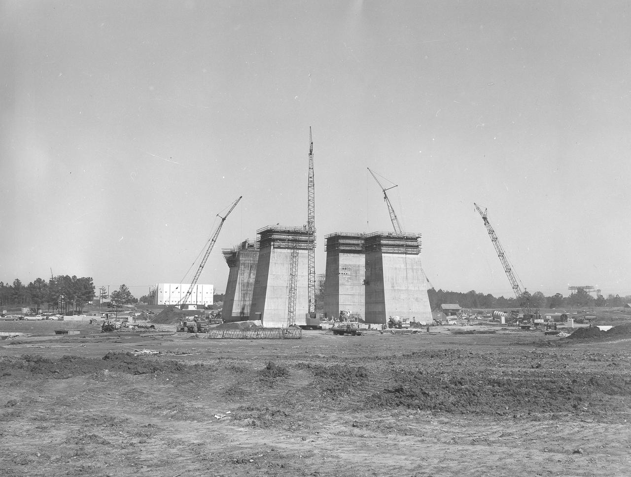
At its founding, the Marshall Space Flight Center (MSFC) inherited the Army’s Jupiter and Redstone test stands, but much larger facilities were needed for the giant stages of the Saturn V. From 1960 to 1964, the existing stands were remodeled and a sizable new test area was developed. The new comprehensive test complex for propulsion and structural dynamics was unique within the nation and the free world, and they remain so today because they were constructed with foresight to meet the future as well as on going needs. Construction of the S-IC Static test stand complex began in 1961 in the west test area of MSFC, and was completed in 1964. The S-IC static test stand was designed to develop and test the 138-ft long and 33-ft diameter Saturn V S-IC first stage, or booster stage, weighing in at 280,000 pounds. Required to hold down the brute force of a 7,500,000-pound thrust produced by 5 F-1 engines, the S-IC static test stand was designed and constructed with the strength of hundreds of tons of steel and 12,000,000 pounds of cement, planted down to bedrock 40 feet below ground level. The foundation walls, constructed with concrete and steel, are 4 feet thick. The base structure consists of four towers with 40-foot-thick walls extending upward 144 feet above ground level. The structure was topped by a crane with a 135-foot boom. With the boom in the upright position, the stand was given an overall height of 405 feet, placing it among the highest structures in Alabama at the time. This photo, depicts the progress of the stand as of January 14, 1963, with its four towers prominently rising.
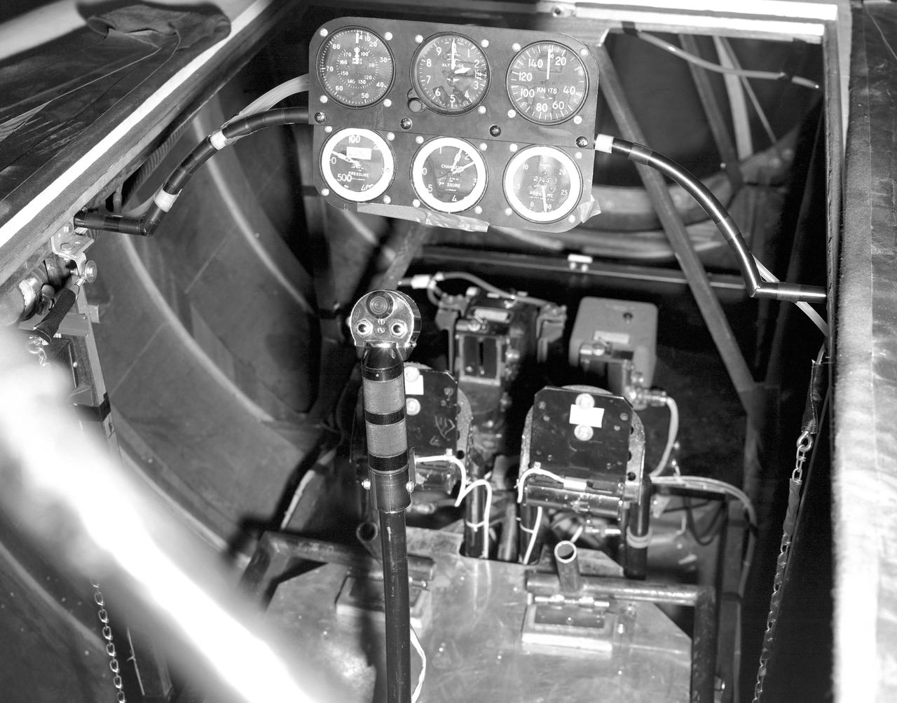
This photo shows the cockpit configuration of the M2-F1 wingless lifting body. With a top speed of about 120 knots, the M2-F1 had a simple instrument panel. Besides the panel itself, the ribs of the wooden shell (left) and the control stick (center) are also visible.
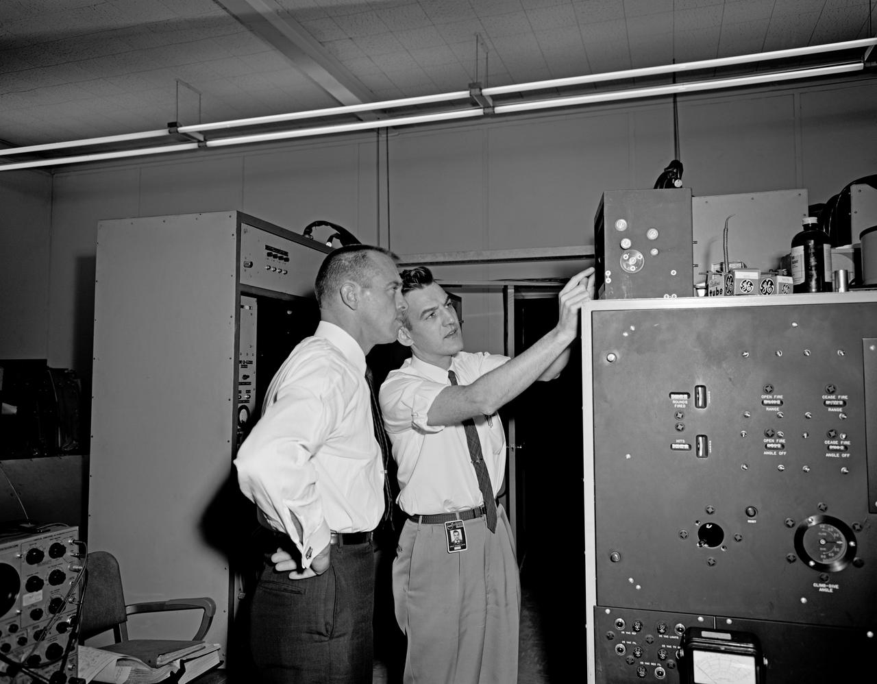
Walter Olson, Chief of the Chemistry and Energy Conversion Division, examines equipment in the new Energy Conversion Laboratory at the National Aeronautics and Space Administration (NASA) Lewis Research Center. The Energy Conversion Laboratory, built in 1961 and 1962, was a modest one-story brick structure with 30,000 square feet of working space. It was used to study fundamental elements pertaining to the conversion of energy into electrical power. The main application for this was space power, but in the 1970s it would also be applied for terrestrial applications. Olson joined the Lewis staff as a fuels and combustion researcher in 1942 and was among a handful or researchers who authored the new laboratory’s first technical report. The laboratory reorganized after the war and Olson was placed in charge of three sections of researchers in the Combustion Branch. They studied combustion and fuels for turbojets, ramjets, and small rockets. In 1950, Olson was named Chief of the entire Fuels and Combustion Research Division. In 1960 Olson was named Chief of the new Chemistry and Energy Conversion Division. It was in this role that Olson advocated for the construction of the Energy Conversion Laboratory. The new division expanded its focus from just fuels and combustion to new sources of energy and power such as solar cells, fuels cells, heat transfer, and thermionics.
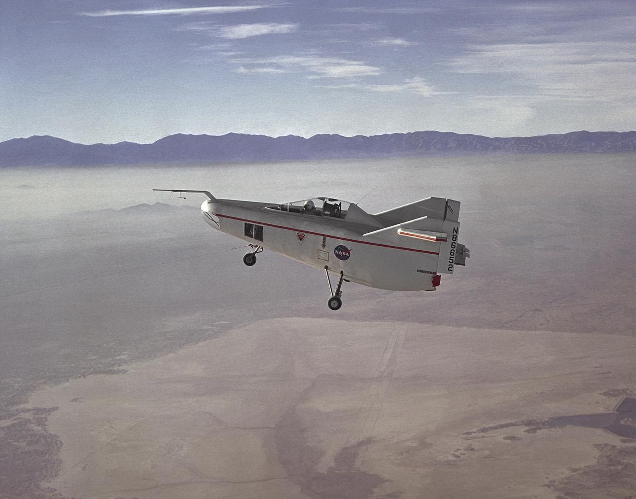
The M2-F1 Lifting Body is seen here under tow, high above Rogers Dry Lake near the Flight Research Center (later redesignated the Dryden Flight Research Center), Edwards, California. R. Dale Reed effectively advocated the project with the support of NASA research pilot Milt Thompson. Together, they gained the support of Flight Research Center Director Paul Bikle. After a six-month feasibility study, Bikle gave approval in the fall of 1962 for the M2-F1 to be built.
![Astronaut Charles Conrad at the controls of the Visual Docking Simulator. From A.W. Vogeley, "Piloted Space-Flight Simulation at Langley Research Center," paper presented at the American Society of Mechanical Engineers 1966 Winter Meeting, New York, NY, November 27-December 1, 1966. "This facility was [later known as the Visual-Optical Simulator.] It presents to the pilot an out-the-window view of his target in correct 6 degrees of freedom motion. The scene is obtained by a television camera pick-up viewing a small-scale gimbaled model of the target." "For docking studies, the docking target picture was projected onto the surface of a 20-foot-diameter sphere and the pilot could, effectively, maneuver into contract. this facility was used in a comparison study with the Rendezvous Docking Simulator - one of the few comparison experiments in which conditions were carefully controlled and a reasonable sample of pilots used. All pilots preferred the more realistic RDS visual scene. The pilots generally liked the RDS angular motion cues although some objected to the false gravity cues that these motions introduced. Training time was shorter on the RDS, but final performance on both simulators was essentially equal. " "For station-keeping studies, since close approach is not required, the target was presented to the pilot through a virtual-image system which projects his view to infinity, providing a more realistic effect. In addition to the target, the system also projects a star and horizon background. "](https://images-assets.nasa.gov/image/LRC-1963-B701_P-09519/LRC-1963-B701_P-09519~medium.jpg)
Astronaut Charles Conrad at the controls of the Visual Docking Simulator. From A.W. Vogeley, "Piloted Space-Flight Simulation at Langley Research Center," paper presented at the American Society of Mechanical Engineers 1966 Winter Meeting, New York, NY, November 27-December 1, 1966. "This facility was [later known as the Visual-Optical Simulator.] It presents to the pilot an out-the-window view of his target in correct 6 degrees of freedom motion. The scene is obtained by a television camera pick-up viewing a small-scale gimbaled model of the target." "For docking studies, the docking target picture was projected onto the surface of a 20-foot-diameter sphere and the pilot could, effectively, maneuver into contract. this facility was used in a comparison study with the Rendezvous Docking Simulator - one of the few comparison experiments in which conditions were carefully controlled and a reasonable sample of pilots used. All pilots preferred the more realistic RDS visual scene. The pilots generally liked the RDS angular motion cues although some objected to the false gravity cues that these motions introduced. Training time was shorter on the RDS, but final performance on both simulators was essentially equal. " "For station-keeping studies, since close approach is not required, the target was presented to the pilot through a virtual-image system which projects his view to infinity, providing a more realistic effect. In addition to the target, the system also projects a star and horizon background. "
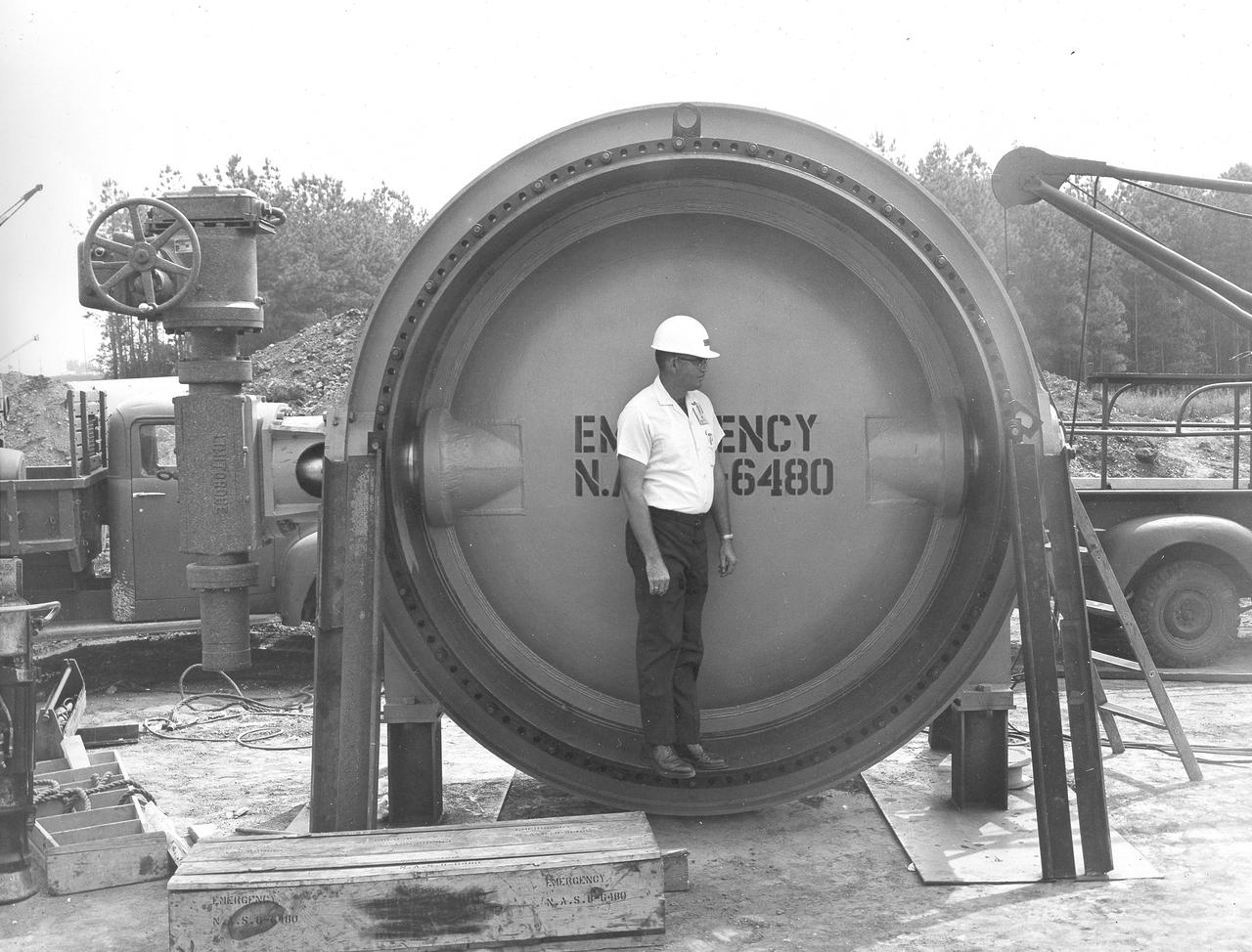
At its founding, the Marshall Space Flight Center (MSFC) inherited the Army’s Jupiter and Redstone test stands, but much larger facilities were needed for the giant stages of the Saturn V. From 1960 to 1964, the existing stands were remodeled and a sizable new test area was developed. The new comprehensive test complex for propulsion and structural dynamics was unique within the nation and the free world, and they remain so today because they were constructed with foresight to meet the future as well as on going needs. Construction of the S-IC Static test stand complex began in 1961 in the west test area of MSFC, and was completed in 1964. The S-IC static test stand was designed to develop and test the 138-ft long and 33-ft diameter Saturn V S-IC first stage, or booster stage, weighing in at 280,000 pounds. Required to hold down the brute force of a 7,500,000-pound thrust produced by 5 F-1 engines, the S-IC static test stand was designed and constructed with the strength of hundreds of tons of steel and 12,000,000 pounds of cement, planted down to bedrock 40 feet below ground level. The foundation walls, constructed with concrete and steel, are 4 feet thick. The base structure consists of four towers with 40-foot-thick walls extending upward 144 feet above ground level. The structure was topped by a crane with a 135-foot boom. With the boom in the upright position, the stand was given an overall height of 405 feet, placing it among the highest structures in Alabama at the time. In addition to the stand itself, related facilities were constructed during this time. Built northeast of the stand was a newly constructed Pump House. Its function was to provide water to the stand to prevent melting damage during testing. The water was sprayed through small holes in the stand’s 1900 ton flame deflector at the rate of 320,000 gallons per minute. In this photograph, a construction worker demonstrates the size of the massive water valve that was used in the testing cooling process.
At its founding, the Marshall Space Flight Center (MSFC) inherited the Army’s Jupiter and Redstone test stands, but much larger facilities were needed for the giant stages of the Saturn V. From 1960 to 1964, the existing stands were remodeled and a sizable new test area was developed. The new comprehensive test complex for propulsion and structural dynamics was unique within the nation and the free world, and they remain so today because they were constructed with foresight to meet the future as well as on going needs. Construction of the S-IC Static test stand complex began in 1961 in the west test area of MSFC, and was completed in 1964. The S-IC static test stand was designed to develop and test the 138-ft long and 33-ft diameter Saturn V S-IC first stage, or booster stage, weighing in at 280,000 pounds. Required to hold down the brute force of a 7,500,000-pound thrust produced by 5 F-1 engines, the S-IC static test stand was designed and constructed with the strength of hundreds of tons of steel and 12,000,000 pounds of cement, planted down to bedrock 40 feet below ground level. The foundation walls, constructed with concrete and steel, are 4 feet thick. The base structure consists of four towers with 40-foot-thick walls extending upward 144 feet above ground level. The structure was topped by a crane with a 135-foot boom. With the boom in the upright position, the stand was given an overall height of 405 feet, placing it among the highest structures in Alabama at the time. In addition to the stand itself, related facilities were constructed during this time. Built to the northeast of the stand was a newly constructed Pump House. Its function was to provide water to the stand to prevent melting damage during testing. The water was sprayed through small holes in the stand’s 1900 ton flame deflector at the rate of 320,000 gallons per minute. This photograph, taken September 25, 1963, depicts the construction progress of the Pump House and massive round water tanks on the right.
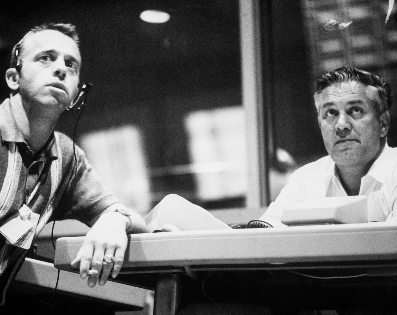
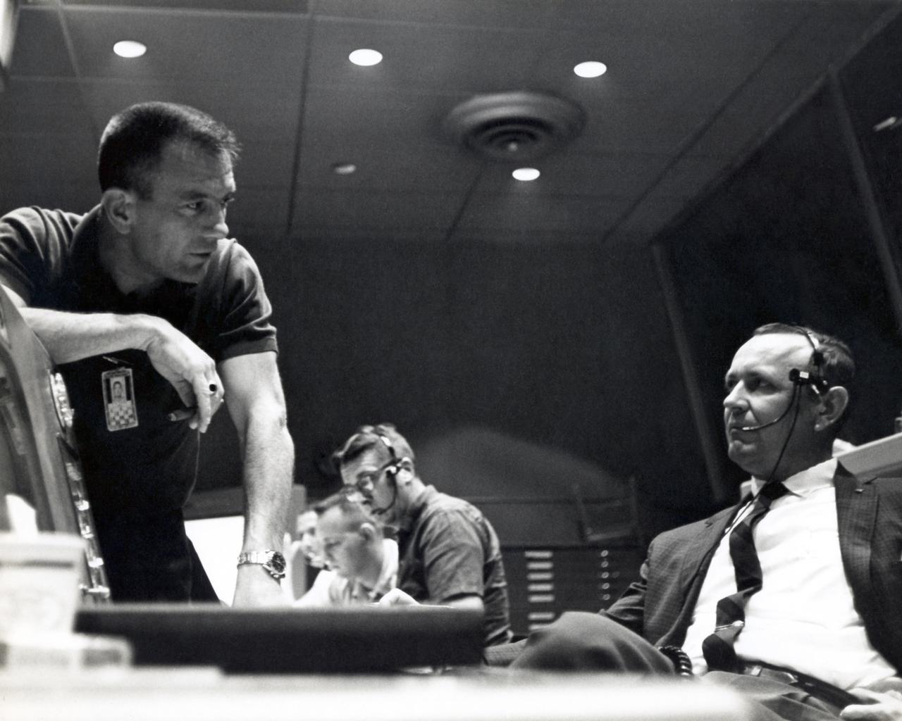
S63-07857 (15-16 May 1963) --- Astronaut Alan Shepard (left) and Walter C. Williams monitor progress of the Mercury Atlas 9 (MA-9) mission from Mercury Control Center, Cape Canaveral, Florida. Photo credit: NASA
IBM 1401 Data Processing System at NASA Ames Research Center.
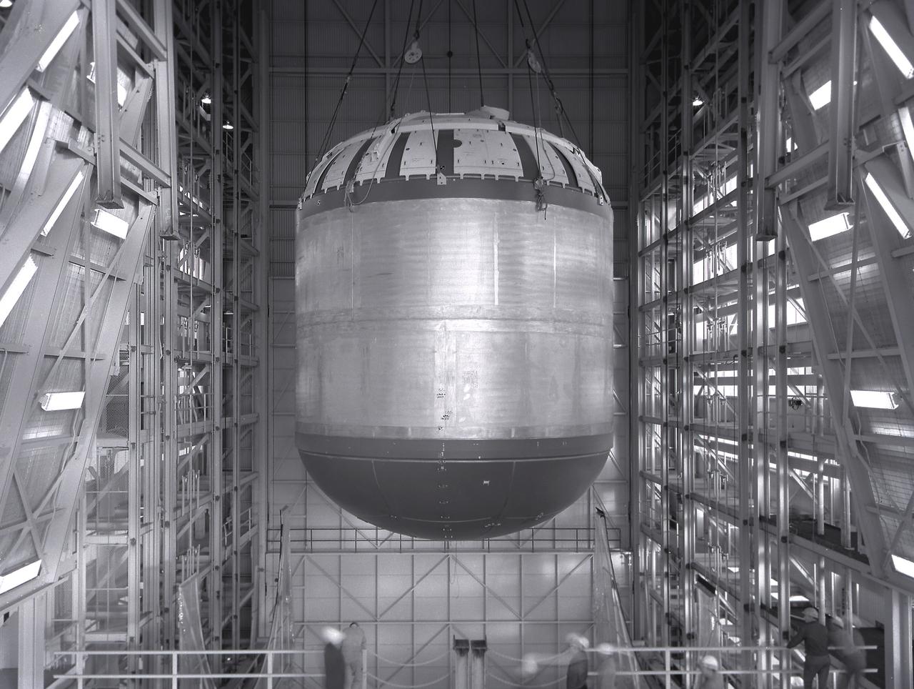
Marshall Space Flight Center successfully conducted hydrostatic testing on the Saturn V S-IC (first) stage fuel tank. The first stage was powered by five F-1 engines, that used liquid oxygen and kerosene as its propellant.
At its founding, the Marshall Space Flight Center (MSFC) inherited the Army’s Jupiter and Redstone test stands, but much larger facilities were needed for the giant stages of the Saturn V. From 1960 to 1964, the existing stands were remodeled and a sizable new test area was developed. The new comprehensive test complex for propulsion and structural dynamics was unique within the nation and the free world, and they remain so today because they were constructed with foresight to meet the future as well as on going needs. Construction of the S-IC Static test stand complex began in 1961 in the west test area of MSFC, and was completed in 1964. The S-IC static test stand was designed to develop and test the 138-ft long and 33-ft diameter Saturn V S-IC first stage, or booster stage, weighing in at 280,000 pounds. Required to hold down the brute force of a 7,500,000-pound thrust produced by 5 F-1 engines, the S-IC static test stand was designed and constructed with the strength of hundreds of tons of steel and 12,000,000 pounds of cement, planted down to bedrock 40 feet below ground level. The foundation walls, constructed with concrete and steel, are 4 feet thick. The base structure consists of four towers with 40-foot-thick walls extending upward 144 feet above ground level. The structure was topped by a crane with a 135-foot boom. With the boom in the upright position, the stand was given an overall height of 405 feet, placing it among the highest structures in Alabama at the time. In addition to the stand itself, related facilities were constructed during this time. Built directly east of the test stand was the Block House, which served as the control center for the test stand. The two were connected by a narrow access tunnel which housed the cables for the controls. Again to the east, just south of the Block House, was a newly constructed Pump House. Its function was to provide water to the stand to prevent melting damage during testing. The water was sprayed through small holes in the stand’s 1900 ton water deflector at the rate of 320,000 gallons per minute. In this photo, taken May 22, 1963, the Pump House is undergoing construction.
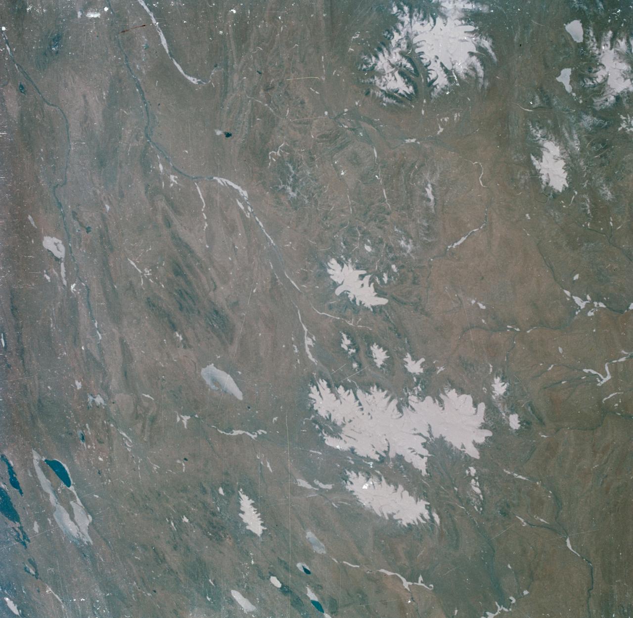
S63-06440 (15-16 May 1963) --- View of the Tibetan Plateau in north-central Tibet, as photographed from the Mercury-Atlas 9 (MA-9) capsule by astronaut L. Gordon Cooper Jr., during his 22-orbit MA-9 spaceflight. The center of the photograph is near 91 degrees east longitude and 34 degrees 30 minutes north latitude. This view includes lakes and snow-covered highlands. Photo credit: NASA
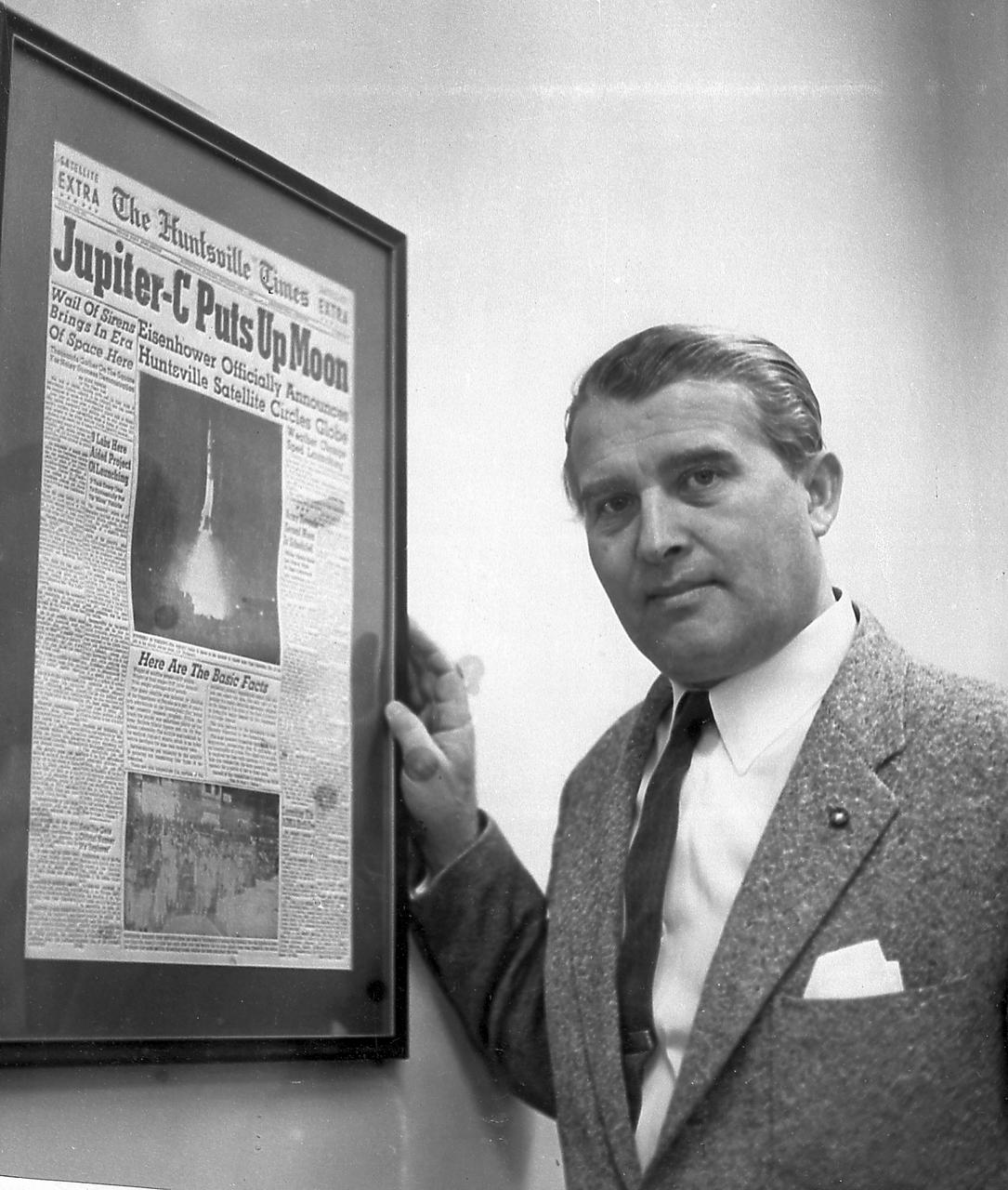
Dr. von Braun is presented with the front page of the Huntsville Times arnouncing the launch of Explorer I, the first U.S. Earth satellite, which was boosted by the Jupiter-C launch vehicle developed by Army Ballistic Missile Agency (ABMA) under the direction of Dr. von Braun. The occasion was the fifth Anniversary of the Explorer I launch in January 1958.
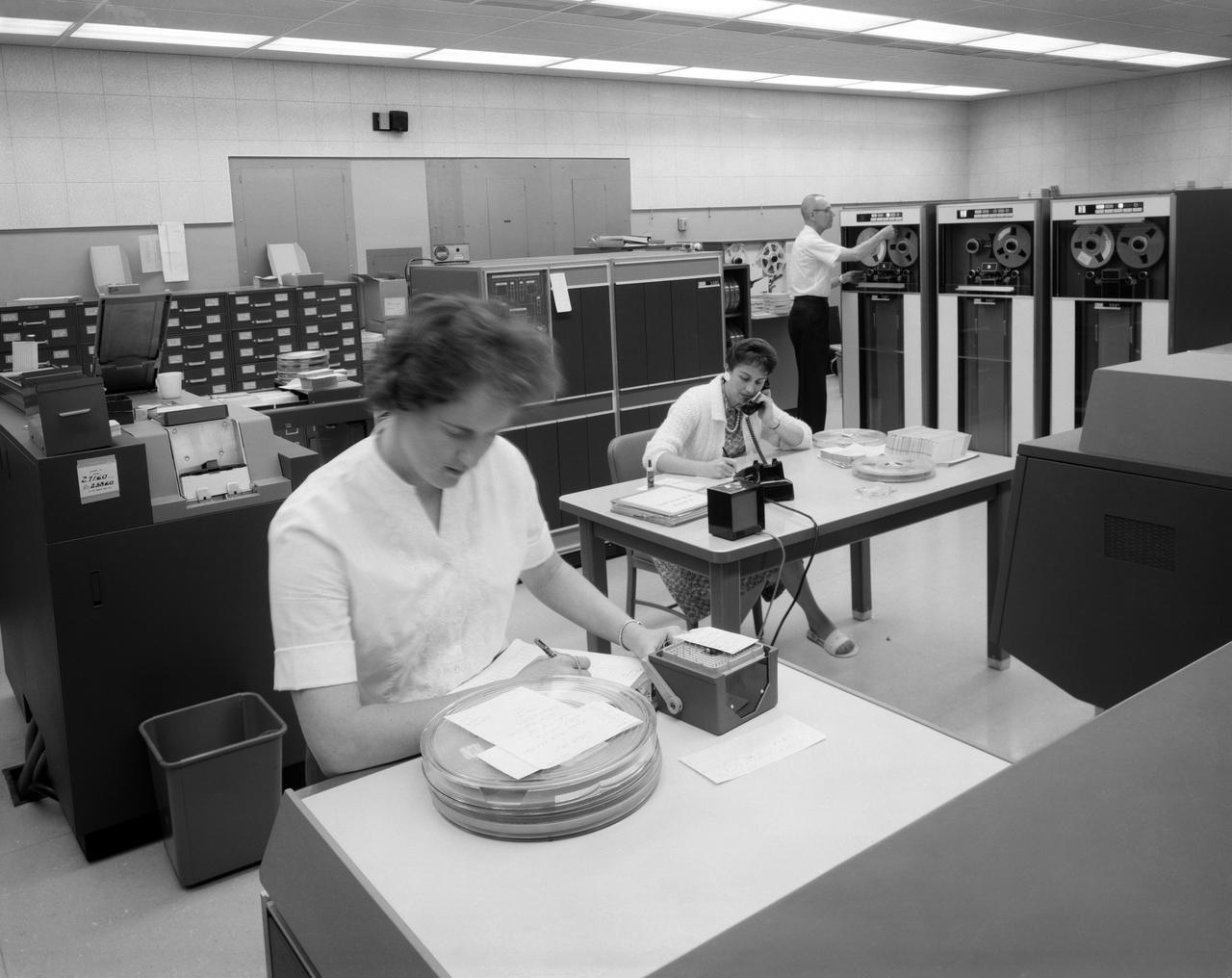
IBM 1401 Data Processing System, at NASA's Ames Research Center.
Side view of assembled command module, tower with flap & launch-escape rocket. Apollo FS-2 in 9 x 7 ft. SupersonicWind Tunnel.
S63-06434 (15-16 May 1963) --- East looking view across Atlantic waters toward Africa, showing Mauritania and Spanish Sahara photographed from the Mercury-Atlas 9 (MA-9) capsule by astronaut L. Gordon Cooper Jr., during his 22-orbit MA-9 spaceflight. Photo credit: NASA
S63-17423 (25 Sept. 1963) --- This easterly view documents early construction of the Manned Spacecraft Center in September of 1963. The Avionics Systems Laboratory (Building 16) is in the foreground and the Project Management Building is see in the right background. Photo credit: NASA
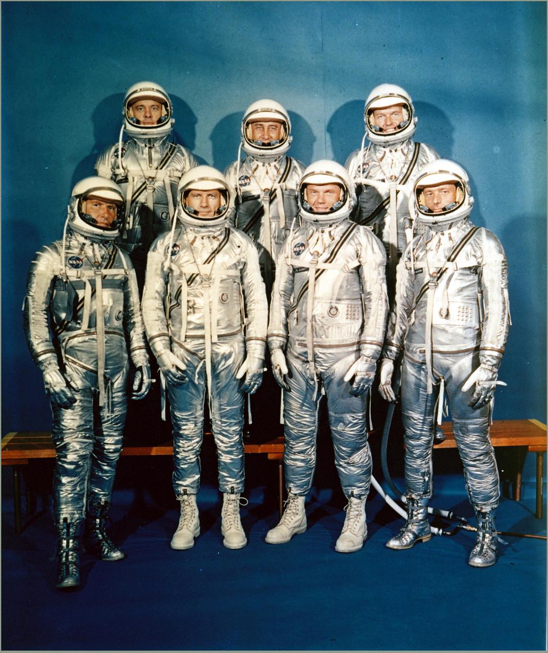
MANNED SPACECRAFT CENTER, HOUSTON, TX. -- FIRST ASTRONAUT TEAM -- Project Mercury Astronauts, whose selection was announced on April 9, 1959, only six months after the National Aeronautics and Space Administration was formally established on Oct. 1, 1958, included: front row, left to right, Walter H. Schirra Jr., Donald K. Slayton, John H. Glenn Jr., and Scott Carpenter back row, Alan B. Shepard Jr., Virgil I. 'Gus' Grissom, and L. Gordon Cooper.
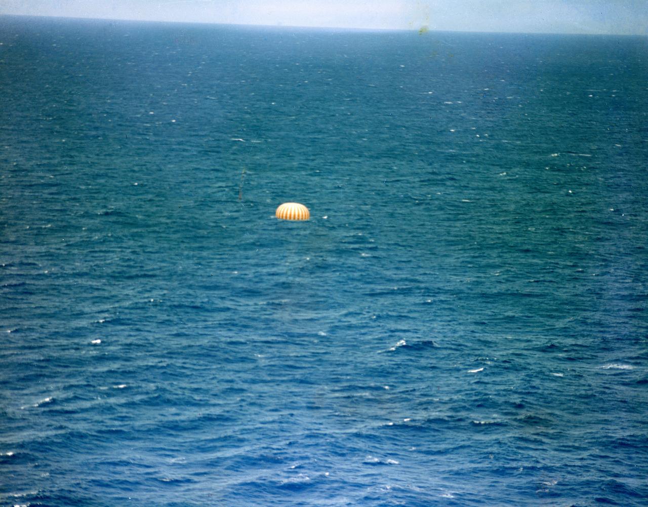
S63-09630 (16 May 1963) --- The Mercury-Atlas 9 (MA-9) "Faith 7" spacecraft, with astronaut L. Gordon Cooper Jr. aboard, nears splashdown in the Pacific Ocean to conclude a 22-orbit mission lasting 34 hours and 20.5 minutes. The capsule's parachute is fully deployed in this view. Photo credit: NASA
CAPE CANAVERAL, Fla. - Mercury astronauts, from left, Wally Schirra, Deke Slayton and Alan Shepard work inside the Mercury Control Center where they were stationed during the Faith 7 mission of astronaut Gordon Cooper, launched on May 15, 1963. This was the final mission of the Mercury Program. The Mercury Mission Control Center in Florida played a key role in the United States' early spaceflight program. Located at Cape Canaveral Air Force Station, the original part of the building was constructed between 1956 and 1958, with additions in 1959 and 1963. The facility officially was transferred to NASA on Dec. 26, 1963, and served as mission control during all the Project Mercury missions, as well as the first three flights of the Gemini Program, when it was renamed Mission Control Center. With its operational days behind, on June 1, 1967, the Mission Control Center became a stop on the public tour of NASA facilities until the mid-90s. In 1999, much of the equipment and furnishings from the Flight Control Area were moved to the Kennedy Space Center Visitor Complex where they became part of the exhibit there. The building was demolished in spring 2010. Photo credit: NASA
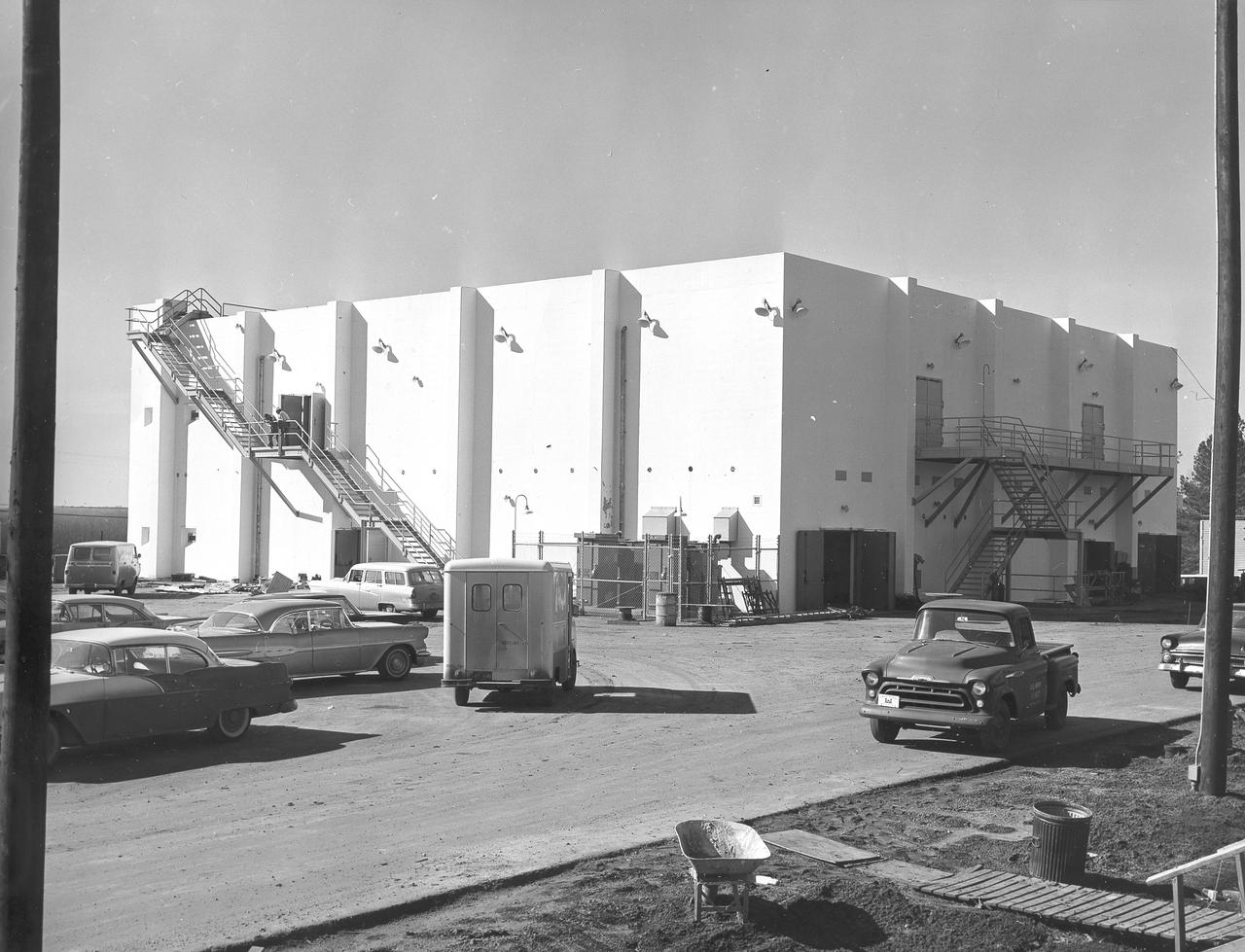
At its founding, the Marshall Space Flight Center (MSFC) inherited the Army’s Jupiter and Redstone test stands, but much larger facilities were needed for the giant stages of the Saturn V. From 1960 to 1964, the existing stands were remodeled and a sizable new test area was developed. The new comprehensive test complex for propulsion and structural dynamics was unique within the nation and the free world, and they remain so today because they were constructed with foresight to meet the future as well as on going needs. Construction of the S-IC Static test stand complex began in 1961 in the west test area of MSFC, and was completed in 1964. The S-IC static test stand was designed to develop and test the 138-ft long and 33-ft diameter Saturn V S-IC first stage, or booster stage, weighing in at 280,000 pounds. Required to hold down the brute force of a 7,500,000-pound thrust produced by 5 F-1 engines, the S-IC static test stand was designed and constructed with the strength of hundreds of tons of steel and 12,000,000 pounds of cement, planted down to bedrock 40 feet below ground level. The foundation walls, constructed with concrete and steel, are 4 feet thick. The base structure consists of four towers with 40-foot-thick walls extending upward 144 feet above ground level. The structure was topped by a crane with a 135-foot boom. With the boom in the upright position, the stand was given an overall height of 405 feet, placing it among the highest structures in Alabama at the time. In addition to the stand itself, related facilities were constructed during this time. Built directly east of the test stand was the Block House, which served as the control center for the test stand. The two were connected by a narrow access tunnel which housed the cables for the controls. In this photo taken February 4, 1963, the Block House exterior is complete.
At its founding, the Marshall Space Flight Center (MSFC) inherited the Army’s Jupiter and Redstone test stands, but much larger facilities were needed for the giant stages of the Saturn V. From 1960 to 1964, the existing stands were remodeled and a sizable new test area was developed. The new comprehensive test complex for propulsion and structural dynamics was unique within the nation and the free world, and they remain so today because they were constructed with foresight to meet the future as well as on going needs. Construction of the S-IC Static test stand complex began in 1961 in the west test area of MSFC, and was completed in 1964. The S-IC static test stand was designed to develop and test the 138-ft long and 33-ft diameter Saturn V S-IC first stage, or booster stage, weighing in at 280,000 pounds. Required to hold down the brute force of a 7,500,000-pound thrust produced by 5 F-1 engines, the S-IC static test stand was designed and constructed with the strength of hundreds of tons of steel and 12,000,000 pounds of cement, planted down to bedrock 40 feet below ground level. The foundation walls, constructed with concrete and steel, are 4 feet thick. The base structure consists of four towers with 40-foot-thick walls extending upward 144 feet above ground level. The structure was topped by a crane with a 135-foot boom. With the boom in the upright position, the stand was given an overall height of 405 feet, placing it among the highest structures in Alabama at the time. This photo shows the progress of the S-IC test stand as of November 20, 1963.
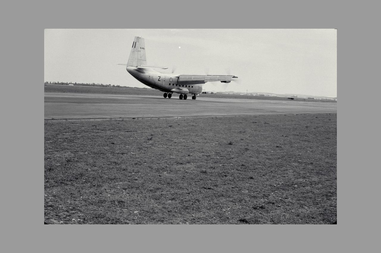
3/4 REAR VIEW OF Breguet 941 AIRPLANE; FLIGHT EVALUATION, MAY 1963. Boundary Layer Control, STOL, and V/STOL Research. Fig. 105 NASA SP Flight Research at Ames: 57 Years of Development and Validation of Aeronautical Technology
Astronaut John Young (above) was one of 14 astronauts, 8 NASA test pilots, and 2 McDonnell test pilots who took part in simulator studies. Young piloted the simulator on November 12, 1963 Arthur Vogeley wrote: "Many of the astronauts have flown this simulator in support of the Gemini studies and they, without exception, appreciated the realism of the visual scene. The simulator has also been used in the development of pilot techniques to handle certain jet malfunctions in order that aborts could be avoided. In these situations large attitude changes are sometimes necessary and the false motion cues that were generated due to earth gravity were somewhat objectionable; however, the pilots were readily able to overlook these false motion cues in favor of the visual realism." Roy F. Brissenden wrote: "The basic Gemini control studies developed the necessary techniques and demonstrated the ability of human pilots to perform final space docking with the specified Gemini-Agena systems using only visual references. ... Results... showed that trained astronauts can effect the docking with direct acceleration control and even with jet malfunctions as long as good visual conditions exist.... Probably more important than data results was the early confidence that the astronauts themselves gained in their ability to perform the maneuver in the ultimate flight mission." -- Published in Barton C. Hacker and James M. Grimwood, On the Shoulders of Titans: A History of Project Gemini, NASA SP-4203; A.W. Vogeley, "Discussion of Existing and Planned Simulators For Space Research," Paper presented at the Conference on the Role of Simulation in Space Technology, August 17-21, 1964; Roy F. Brissenden, "Initial Operations with Langley's Rendezvous Docking Facility," Langley Working Paper, LWP-21, 1964.
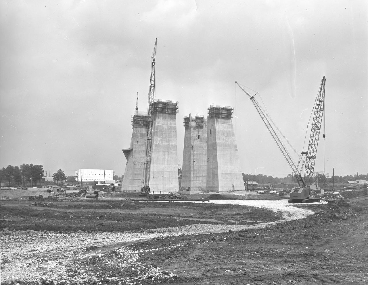
At its founding, the Marshall Space Flight Center (MSFC) inherited the Army’s Jupiter and Redstone test stands, but much larger facilities were needed for the giant stages of the Saturn V. From 1960 to 1964, the existing stands were remodeled and a sizable new test area was developed. The new comprehensive test complex for propulsion and structural dynamics was unique within the nation and the free world, and they remain so today because they were constructed with foresight to meet the future as well as on going needs. Construction of the S-IC Static test stand complex began in 1961 in the west test area of MSFC, and was completed in 1964. The S-IC static test stand was designed to develop and test the 138-ft long and 33-ft diameter Saturn V S-IC first stage, or booster stage, weighing in at 280,000 pounds. Required to hold down the brute force of a 7,500,000-pound thrust produced by 5 F-1 engines, the S-IC static test stand was designed and constructed with the strength of hundreds of tons of steel and 12,000,000 pounds of cement, planted down to bedrock 40 feet below ground level. The foundation walls, constructed with concrete and steel, are 4 feet thick. The base structure consists of four towers with 40-foot-thick walls extending upward 144 feet above ground level. The structure was topped by a crane with a 135-foot boom. With the boom in the upright position, the stand was given an overall height of 405 feet, placing it among the highest structures in Alabama at the time. In this photo, taken June 24, 1963, the four tower legs of the test stand can be seen at their maximum height.
At its founding, the Marshall Space Flight Center (MSFC) inherited the Army’s Jupiter and Redstone test stands, but much larger facilities were needed for the giant stages of the Saturn V. From 1960 to 1964, the existing stands were remodeled and a sizable new test area was developed. The new comprehensive test complex for propulsion and structural dynamics was unique within the nation and the free world, and they remain so today because they were constructed with foresight to meet the future as well as on going needs. Construction of the S-IC Static test stand complex began in 1961 in the west test area of MSFC, and was completed in 1964. The S-IC static test stand was designed to develop and test the 138-ft long and 33-ft diameter Saturn V S-IC first stage, or booster stage, weighing in at 280,000 pounds. Required to hold down the brute force of a 7,500,000-pound thrust produced by 5 F-1 engines, the S-IC static test stand was designed and constructed with the strength of hundreds of tons of steel and 12,000,000 pounds of cement, planted down to bedrock 40 feet below ground level. The foundation walls, constructed with concrete and steel, are 4 feet thick. The base structure consists of four towers with 40-foot-thick walls extending upward 144 feet above ground level. The structure was topped by a crane with a 135-foot boom. With the boom in the upright position, the stand was given an overall height of 405 feet, placing it among the highest structures in Alabama at the time. In addition to the stand itself, related facilities were constructed during this time. Built directly east of the test stand was the Block House, which served as the control center for the test stand. The two were connected by a narrow access tunnel which housed the cables for the controls. This photograph, taken February 25, 1963, gives a close up look at the completed Block House. The side shown faces the S-IC Test Stand.
3/4 front view of Douglas F5D Skylancer modified to "ogee" platform inlet plug installed in Ames 40x80 foot wind tunnel.
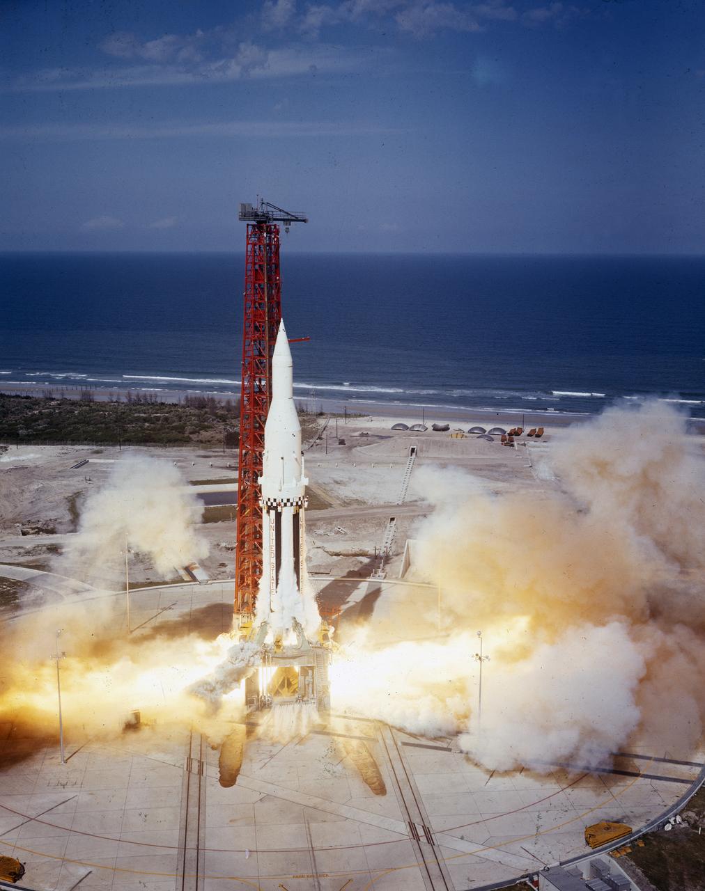
The Saturn I (SA-4) flight lifted off from Kennedy Space Center launch Complex 34, March 28, 1963. The fourth launch of Saturn launch vehicles developed at the Marshall Space Flight Center (MSFC), under the direction of Dr. Wernher von Braun, incorporated a Saturn I, Block I engine. The typical height of a Block I vehicle was approximately 163 feet and had only one live stage. It consisted of eight tanks, each 70 inches in diameter, clustered around a central tank, 105 inches in diameter. Four of the external tanks were fuel tanks for the RP-1 (kerosene) fuel. The other four, spaced alternately with the fuel tanks, were liquid oxygen tanks as was the large center tank. All fuel tanks and liquid oxygen tanks drained at the same rates respectively. The thrust for the stage came from eight H-1 engines, each producing a thrust of 165,000 pounds, for a total thrust of over 1,300,000 pounds. The engines were arranged in a double pattern. Four engines, located inboard, were fixed in a square pattern around the stage axis and canted outward slightly, while the remaining four engines were located outboard in a larger square pattern offset 40 degrees from the inner pattern. Unlike the inner engines, each outer engine was gimbaled. That is, each could be swung through an arc. They were gimbaled as a means of steering the rocket, by letting the instrumentation of the rocket correct any deviations of its powered trajectory. The block I required engine gimabling as the only method of guiding and stabilizing the rocket through the lower atmosphere. The upper stages of the Block I rocket reflected the three-stage configuration of the Saturn I vehicle. Like SA-3, the SA-4 flight’s upper stage ejected 113,560 liters (30,000 gallons) of ballast water in the upper atmosphere for "Project Highwater" physics experiment. Release of this vast quantity of water in a near-space environment marked the second purely scientific large-scale experiment. The SA-4 was the last Block I rocket launch.
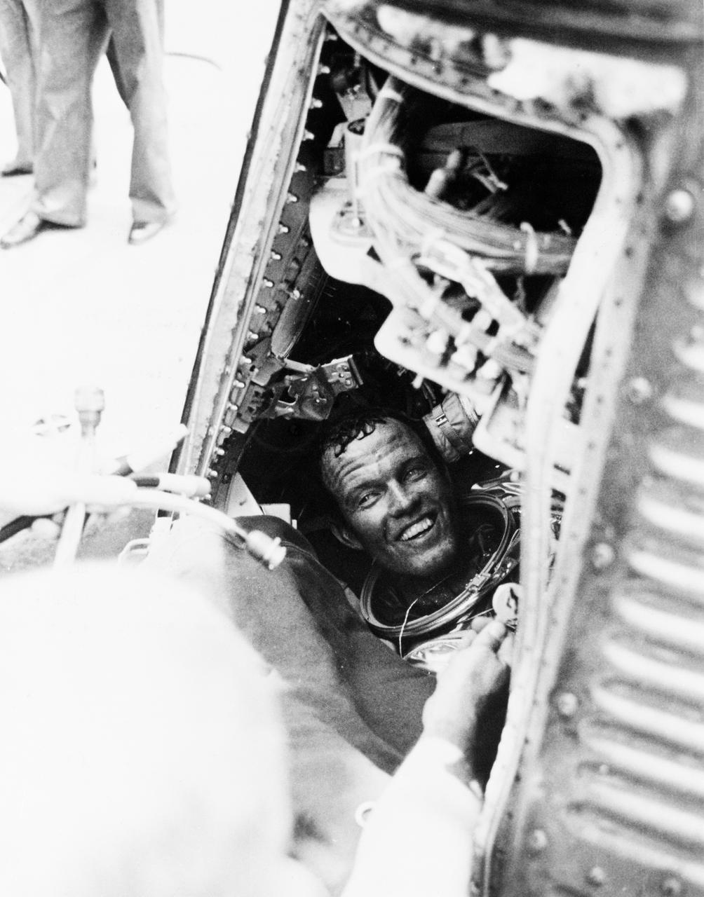
S63-07852 (16 May 1963)--- Astronaut L. Gordon Cooper Jr., pilot of the Mercury-Atlas 9 (MA-9) mission, has a smile for the recovery crew of the USS Kearsarge, after he is onboard from a successful 22-orbit mission of Earth in his spacecraft "Faith 7". Cooper is still sitting in his capsule, with his helmet off. Photo credit: NASA
CAPE CANAVERAL, Fla. - Between 1962 and 1963, the Mission Control Center was modified to handle the additional complexities of the Gemini Program. In 1962, Pan American World Airways Inc. was contracted to design an addition to the facility, which wrapped around the east, north, and most of the west and south sides. The Mercury Mission Control Center in Florida played a key role in the United States' early spaceflight program. Located at Cape Canaveral Air Force Station, the original part of the building was constructed between 1956 and 1958, with additions in 1959 and 1963. The facility officially was transferred to NASA on Dec. 26, 1963, and served as mission control during all the Project Mercury missions, as well as the first three flights of the Gemini Program, when it was renamed Mission Control Center. With its operational days behind, on June 1, 1967, the Mission Control Center became a stop on the public tour of NASA facilities until the mid-90s. In 1999, much of the equipment and furnishings from the Flight Control Area were moved to the Kennedy Space Center Visitor Complex where they became part of the exhibit there. The building was demolished in spring 2010. Photo credit: NASA
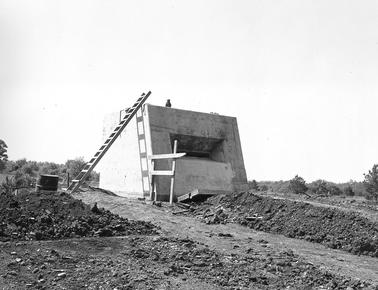
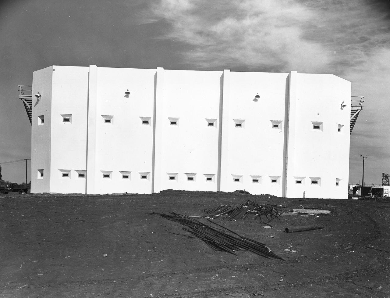
At its founding, the Marshall Space Flight Center (MSFC) inherited the Army’s Jupiter and Redstone test stands, but much larger facilities were needed for the giant stages of the Saturn V. From 1960 to 1964, the existing stands were remodeled and a sizable new test area was developed. The new comprehensive test complex for propulsion and structural dynamics was unique within the nation and the free world, and they remain so today because they were constructed with foresight to meet the future as well as on going needs. Construction of the S-IC Static test stand complex began in 1961 in the west test area of MSFC, and was completed in 1964. The S-IC static test stand was designed to develop and test the 138-ft long and 33-ft diameter Saturn V S-IC first stage, or booster stage, weighing in at 280,000 pounds. Required to hold down the brute force of a 7,500,000-pound thrust produced by 5 F-1 engines, the S-IC static test stand was designed and constructed with the strength of hundreds of tons of steel and 12,000,000 pounds of cement, planted down to bedrock 40 feet below ground level. The foundation walls, constructed with concrete and steel, are 4 feet thick. The base structure consists of four towers with 40-foot-thick walls extending upward 144 feet above ground level. The structure was topped by a crane with a 135-foot boom. With the boom in the upright position, the stand was given an overall height of 405 feet, placing it among the highest structures in Alabama at the time. In addition to the S-IC stand, additional related facilities were built during this time frame. Built to the east of the S-IC stand, the block house served as the control room. To the south of the blockhouse was a newly constructed pump house used for delivering water to the S-IC stand during testing. North of the massive test stand, the F-1 Engine test stand was built for testing a single F-1 engine. Just southeast of the S-IC stand a concrete bunker house was constructed. The bunker housed an emergency crew clad in fire proof gear, who were close at hand should any emergencies arise during testing. This photo of the completed bunker house was taken on May 7, 1963.
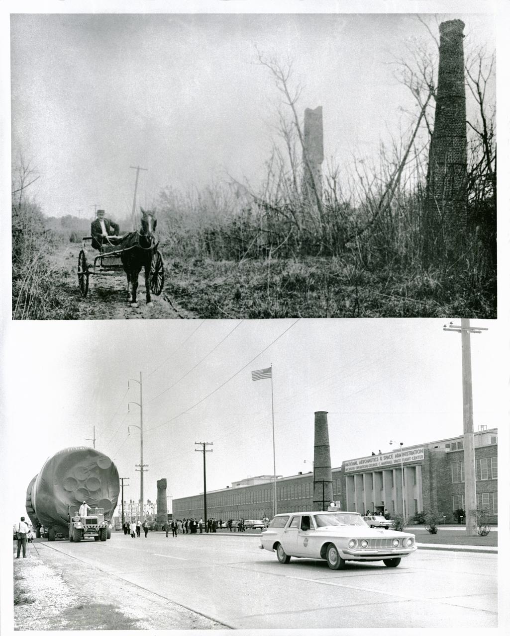
NASA's Michoud Assembly Facility, located in eastern New Orleans, Louisiana, is an 832 acre site that is a government-owned, contractor-operated component of the George C. Marshall Space Flight Center (MSFC). The facility was acquired by NASA in 1961 at the recommendation of Dr. Wernher von Braun and his rocket team in Huntsville Alabama. The cavernous plant served as the assembly facility for the Saturn launch vehicles and most recently the external tank (ET) used for the Space Shuttle Program. The facility features one of the world's biggest manufacturing plants with 43 acres under one roof and a port with deep-water access for the transportation of large space structures. When completed, space hardware is towed on a barge across the Gulf of Mexico, around Florida and up to Kennedy Space Center. The original tract of land was part of a 34,500 acre French Royal land grant to local merchant, Gilbert Antoine de St. Maxent in 1763. Later, the land was acquired by French transplant Antoine Michoud, the son of Napoleon's Administrator of Domains, who moved to the city in 1827. Michoud operated a sugar cane plantation and refinery on the site until his death in 1863. His heirs continued operating the refinery and kept the original St. Maxent estate intact into the 20th century. Two brick smokestacks from the original refinery still stand before the Michoud facility today as seen in the lower half of this photograph taken in the 1960's, while the upper half reflects the area during the time of the sugar cane plantation workers.
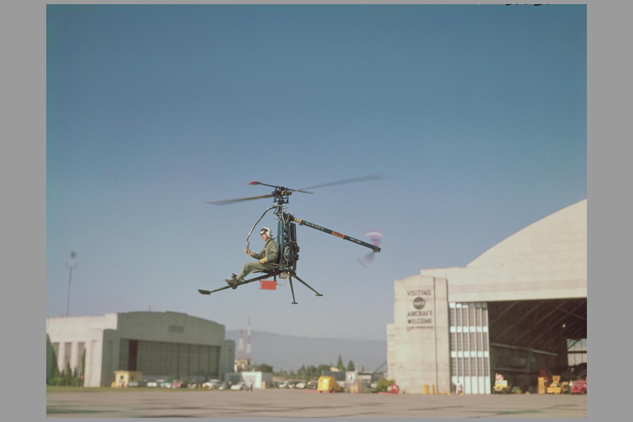
Ames aerodynamicists tested a wide variety of VTOL aircraft and helicopters during the 1960's. Here the Hiller rotorcycle YROE-1, made by Hiller Helicopter in nearby PaloAlto, California, hovers in front of the Ames Hangar. (4020, 4021, 4024) Published in NASA SP Flight Research at Ames: 57 Years of Development and Validation of Aeronautical Technology and Ames 60yr History Atmosphere of Freedom.
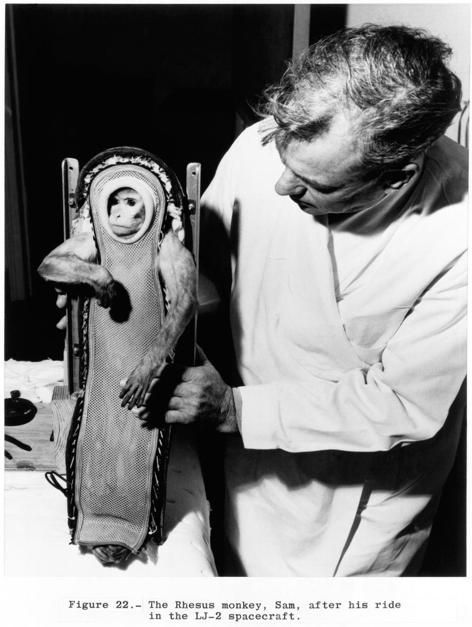
S63-19199 (4 Dec. 1959) --- Sam, the Rhesus monkey, and his handler after his ride in the Little Joe 2 (LJ-2) spacecraft. He is still encased in his contour couch. A U.S. Navy destroyer safely recovered Sam after he experienced three minutes of weightlessness during the flight. Photo credit: NASA
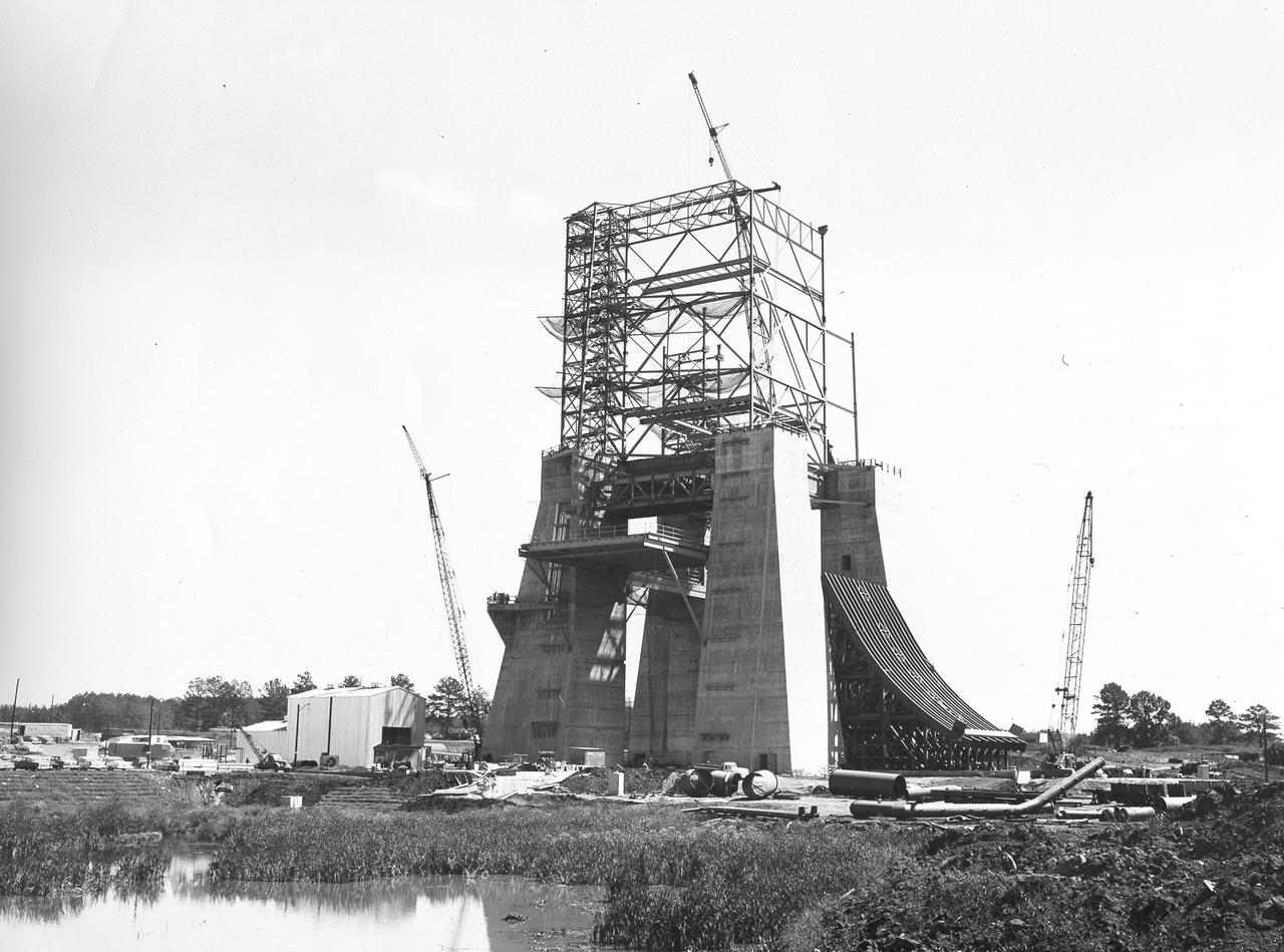
At its founding, the Marshall Space Flight Center (MSFC) inherited the Army’s Jupiter and Redstone test stands, but much larger facilities were needed for the giant stages of the Saturn V. From 1960 to 1964, the existing stands were remodeled and a sizable new test area was developed. The new comprehensive test complex for propulsion and structural dynamics was unique within the nation and the free world, and they remain so today because they were constructed with foresight to meet the future as well as on going needs. Construction of the S-IC Static test stand complex began in 1961 in the west test area of MSFC, and was completed in 1964. The S-IC static test stand was designed to develop and test the 138-ft long and 33-ft diameter Saturn V S-IC first stage, or booster stage, weighing in at 280,000 pounds. Required to hold down the brute force of a 7,500,000-pound thrust produced by 5 F-1 engines, the S-IC static test stand was designed and constructed with the strength of hundreds of tons of steel and 12,000,000 pounds of cement, planted down to bedrock 40 feet below ground level. The foundation walls, constructed with concrete and steel, are 4 feet thick. The base structure consists of four towers with 40-foot-thick walls extending upward 144 feet above ground level. The structure was topped by a crane with a 135-foot boom. With the boom in the upright position, the stand was given an overall height of 405 feet, placing it among the highest structures in Alabama at the time. In addition to the stand itself, related facilities were constructed during this time. Built to the northeast of the stand was a newly constructed Pump House. Its function was to provide water to the stand to prevent melting damage during testing. The water was sprayed through small holes in the stand’s 1900 ton flame deflector at the rate of 320,000 gallons per minute. In this photo of the S-IC test stand, taken September 25, 1963, the flame deflector can be seen rotated to the outside on the right. The deflector was assembled on tracks for mobility.
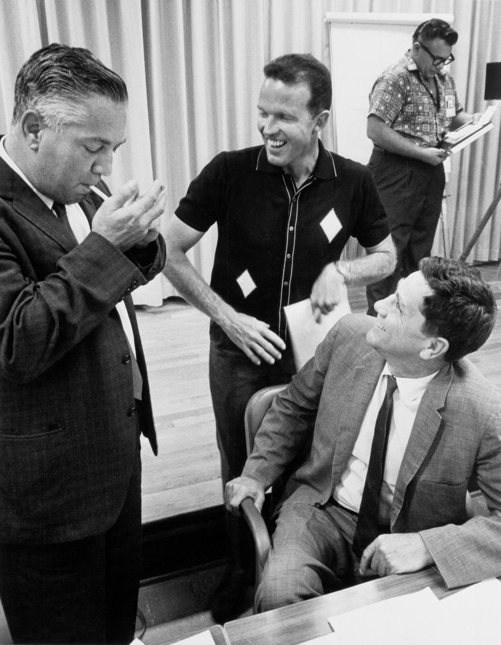
S63-06123 (1963) --- Walter C. Williams, astronaut L. Gordon Cooper Jr., and Merritt Preston are pictured during an Mercury Atlas 9 (MA-9) prelaunch mission review. Photo credit: NASA
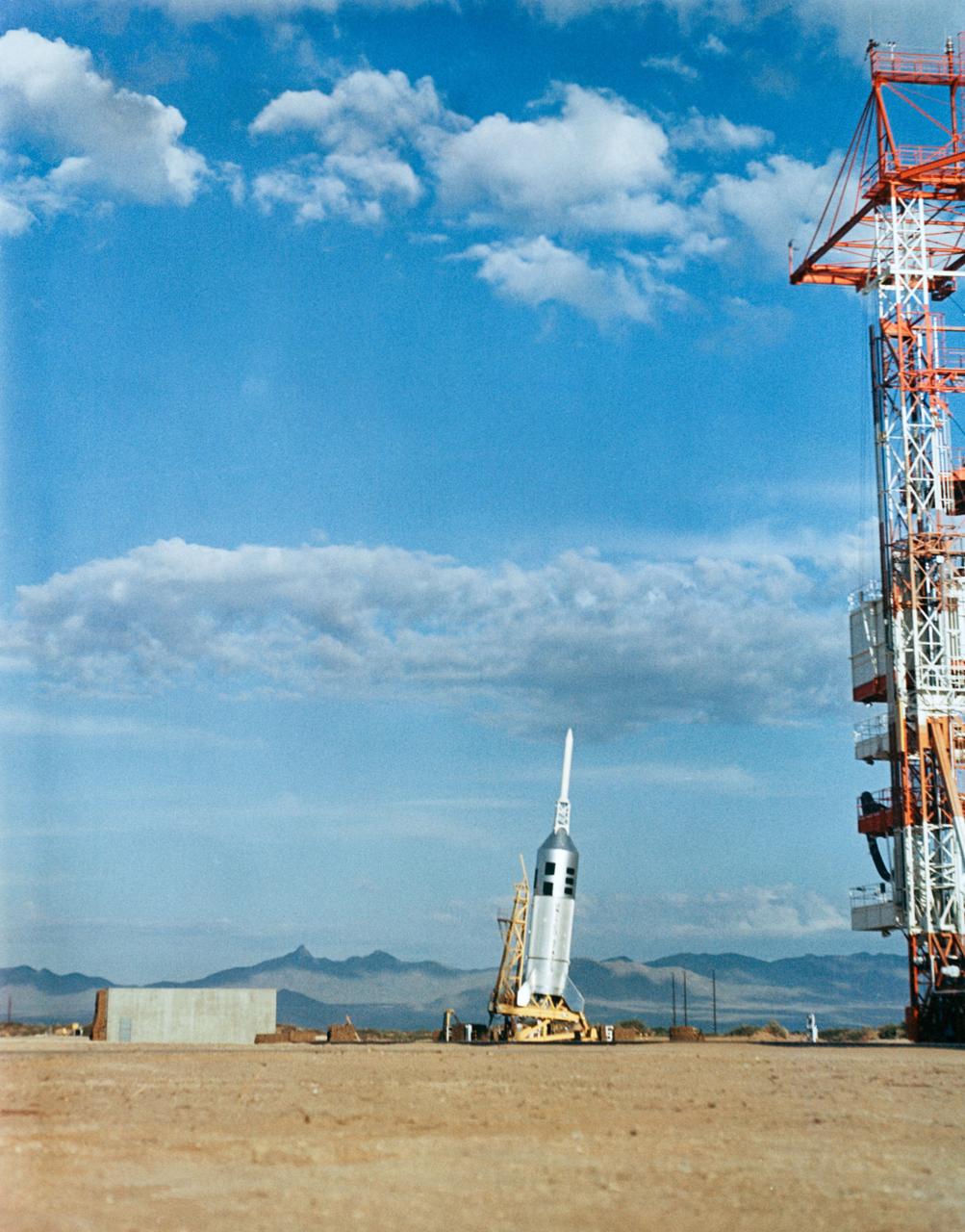
Little Joe II liftoff from the Apollo Little Joe II launch area #3 at White Sands Missile Range, White Sands, New Mexico.
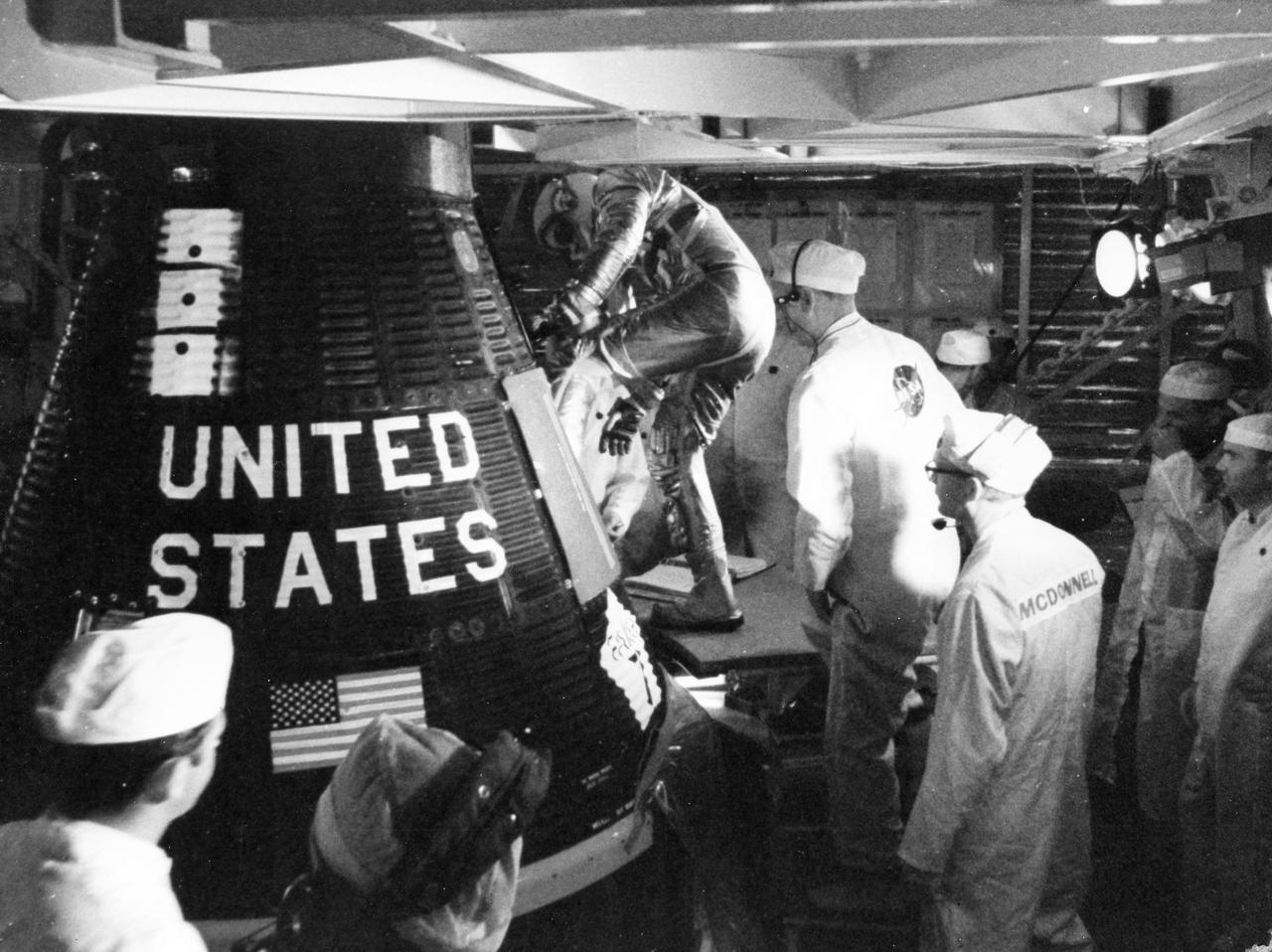
S63-06259 (14 May 1963) --- Astronaut L. Gordon Cooper Jr., prime pilot for the Mercury-Atlas 9 (MA-9) mission, is assisted into his "Faith 7" Mercury spacecraft early morning on May 14, 1963. Cooper remained in the spacecraft for approximately five hours and then climbed out again as the mission was delayed because of trouble at a tracking station. Photo credit: NASA
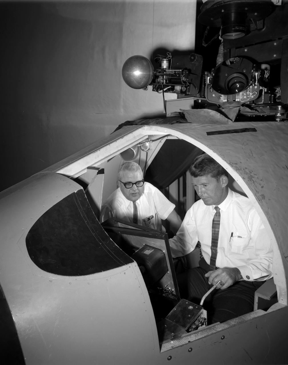
Walter (Wally) M. Schirra in Visual Docking Simulator From A.W. Vogeley, "Piloted Space-Flight Simulation at Langley Research Center," Paper presented at the American Society of Mechanical Engineers 1966 Winter Meeting, New York, NY, November 27-December 1, 1966. "This facility was [later known as the Visual-Optical Simulator. It presents to the pilot an out-the-window view of his target in correct 6 degrees of freedom motion. The scene is obtained by a television camera pick-up viewing a small-scale gimbaled model of the target. "For docking studies, the docking target picture was projected onto the surface of a 20-foot-diameter sphere and the pilot could, effectively, maneuver into contract. this facility was used in a comparison study with the Rendezvous Docking Simulator - one of the few comparison experiments in which conditions were carefully controlled and a reasonable sample of pilots used. All pilots preferred the more realistic RDS visual scene. The pilots generally liked the RDS angular motion cues although some objected to the false gravity cues that these motions introduced. Training time was shorter on the RDS, but final performance on both simulators was essentially equal. " "For station-keeping studies, since close approach is not required, the target was presented to the pilot through a virtual-image system which projects his view to infinity, providing a more realistic effect. In addition to the target, the system also projects a star and horizon background. "
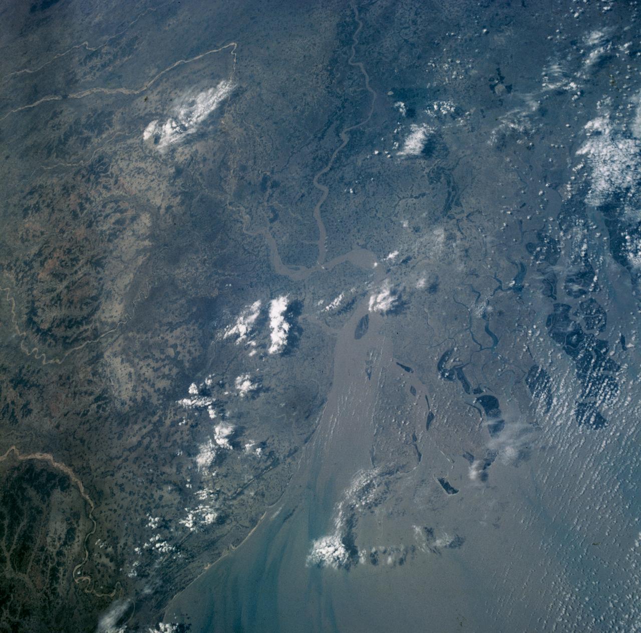
S63-06435 (15-16 May 1963) --- Part of the Ganges delta near Calcutta, as photographed from the Mercury-Atlas 9 (MA-9) capsule by astronaut L. Gordon Cooper Jr., during his 22-orbit MA-9 spaceflight. Photo credit: NASA
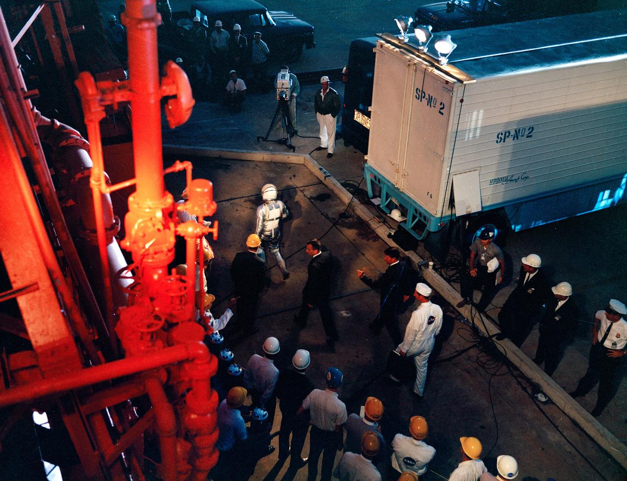
S63-07632 (15 May 1963) --- Astronaut L. Gordon Cooper Jr. leaves the transfer van for the launch pad and the beginning of the Mercury-Atlas 9 (MA-9) flight on May 15, 1963. Photo credit: NASA
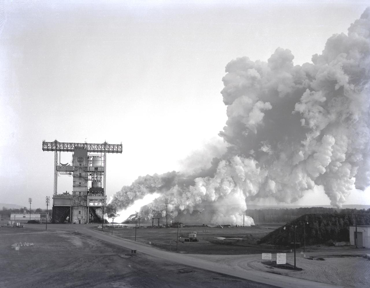
The test laboratory of the Marshall Space Flight Center (MSFC) tested the F-1 engine, the most powerful rocket engine ever fired at MSFC. The engine was tested on the newly modified Saturn IB Static Test Stand which had been used for three years to test the Saturn I eight-engine booster, S-I (first) stage. In 1961 the test stand was modified to permit static firing of the S-I/S-IB stage and the name of the stand was then changed to the S-IB Static Test Stand. Producing a combined thrust of 7,500,000 pounds, five F-1 engines powered the S-IC (first) stage of the Saturn V vehicle for the marned lunar mission.
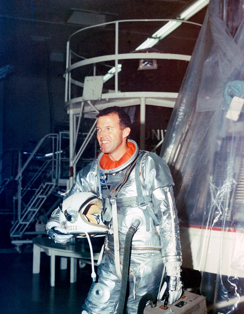
S63-01922 (1963) --- Astronaut L. Gordon Cooper Jr., pilot for the Mercury-Atlas 9 (MA-9) mission, stands fully suited beside his spacecraft during preflight testing. Cooper named his spacecraft the Faith 7. Photo credit: NASA