
CAPE CANAVERAL, Fla. - Renamed the Mission Control Center, the facility continued to be the flight control through the first three missions of Project Gemini. The Mercury Mission Control Center in Florida played a key role in the United States' early spaceflight program. Located at Cape Canaveral Air Force Station, the original part of the building was constructed between 1956 and 1958, with additions in 1959 and 1963. The facility officially was transferred to NASA on Dec. 26, 1963, and served as mission control during all the Project Mercury missions, as well as the first three flights of the Gemini Program, when it was renamed Mission Control Center. With its operational days behind, on June 1, 1967, the Mission Control Center became a stop on the public tour of NASA facilities until the mid-90s. In 1999, much of the equipment and furnishings from the Flight Control Area were moved to the Kennedy Space Center Visitor Complex where they became part of the exhibit there. The building was demolished in spring 2010. Photo credit: NASA
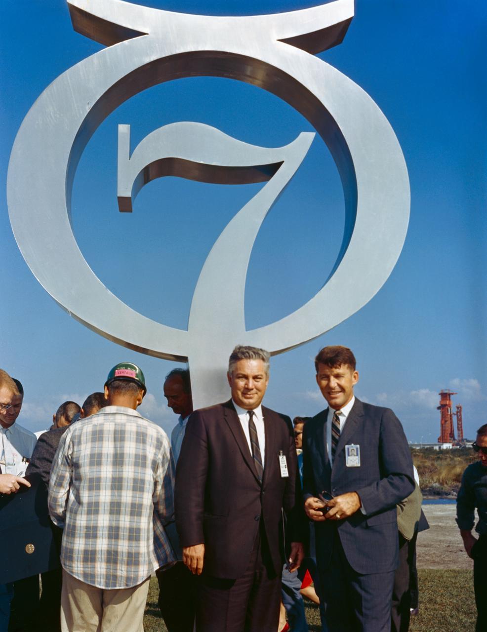
S64-40113 (1964) --- Astronaut Walter Schirra Jr. (right) and Walter Williams, Deputy Director of Mission Requirements, pictured at the Mercury 7 memorial dedication. Photo credit: NASA
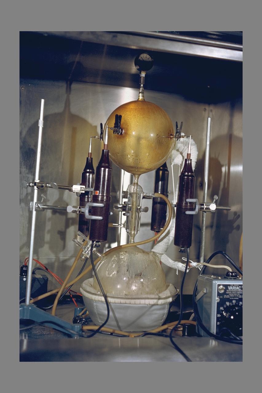
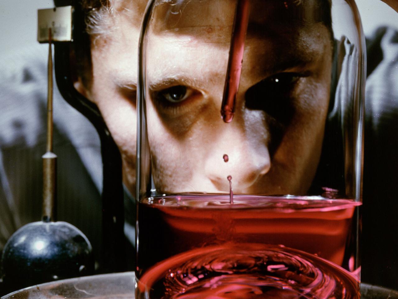
Ames Photographer: Zebow Electric Discharge Apparatus used on the studies of the origin of life
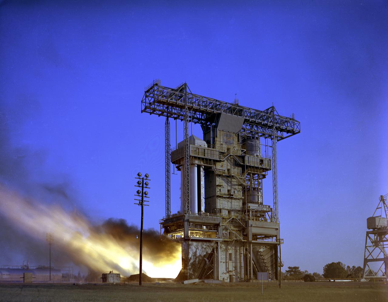
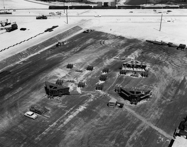
Test firing of the Saturn I S-I Stage (S-1-10) at the Marshall Space Flight Center. This test stand was originally constructed in 1951 and sometimes called the Redstone or T tower. In l961, the test stand was modified to permit static firing of the S-I/S-IB stages, which produced a total thrust of 1,600,000 pounds. The name of the stand was then changed to the S-IB Static Test Stand.
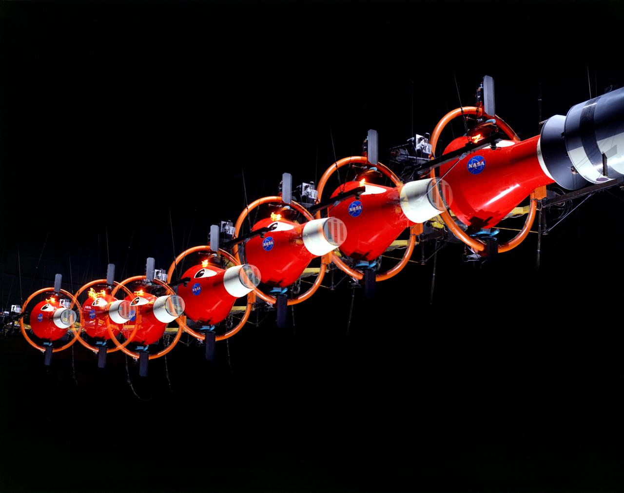
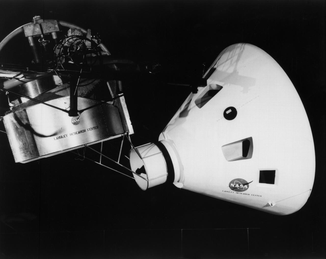
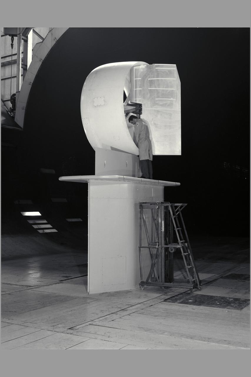
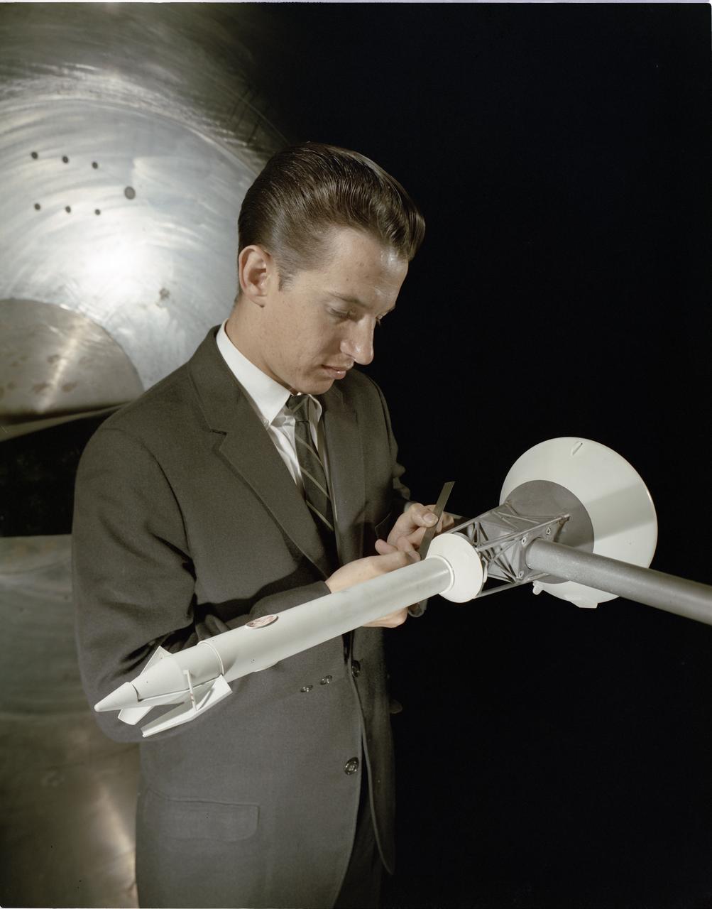
Multiple exposure of Rendezvous Docking Simulator. Francis B. Smith, described the simulator as follows: The rendezvous and docking operation of the Gemini spacecraft with the Agena and of the Apollo Command Module with the Lunar Excursion Module have been the subject of simulator studies for several years. This figure illustrates the Gemini-Agena rendezvous docking simulator at Langley. The Gemini spacecraft was supported in a gimbal system by an overhead crane and gantry arrangement which provided 6 degrees of freedom - roll, pitch, yaw, and translation in any direction - all controllable by the astronaut in the spacecraft. Here again the controls fed into a computer which in turn provided an input to the servos driving the spacecraft so that it responded to control motions in a manner which accurately simulated the Gemini spacecraft. -- Published in Barton C. Hacker and James M. Grimwood, On the Shoulders of Titans: A History of Project Gemini, NASA SP-4203 Francis B. Smith, Simulators for Manned Space Research, Paper presented at the 1966 IEEE International convention, March 21-25, 1966.
Dr Harold Klein discusses work with Congressman William K Van Pelt during visit and tour of Ames
Engineer Paul Reader and his colleagues take environmental measurements during testing of a 20-inch diameter ion engine in a vacuum tank at the Electric Propulsion Laboratory (EPL). Researchers at the Lewis Research Center were investigating the use of a permanent-magnet circuit to create the magnetic field required power electron bombardment ion engines. Typical ion engines use a solenoid coil to create this magnetic field. It was thought that the substitution of a permanent magnet would create a comparable magnetic field with a lower weight. Testing of the magnet system in the EPL vacuum tanks revealed no significant operational problems. Reader found the weight of the two systems was similar, but that the thruster’s efficiency increased with the magnet. The EPL contained a series of large vacuum tanks that could be used to simulate conditions in space. Large vacuum pumps reduced the internal air pressure, and a refrigeration system created the cryogenic temperatures found in space.
View of CT Assembly
The fuel tank assembly of the Saturn V S-IC (first) stage is readied to be mated to the liquid oxygen tank at the Marshall Space Flight Center. The fuel tank carried kerosene as its fuel. The S-IC stage utilized five F-1 engines that used kerosene and liquid oxygen as propellant. Each engine provided 1,500,000 pounds of thrust. This stage lifted the entire vehicle and Apollo spacecraft from the launch pad.
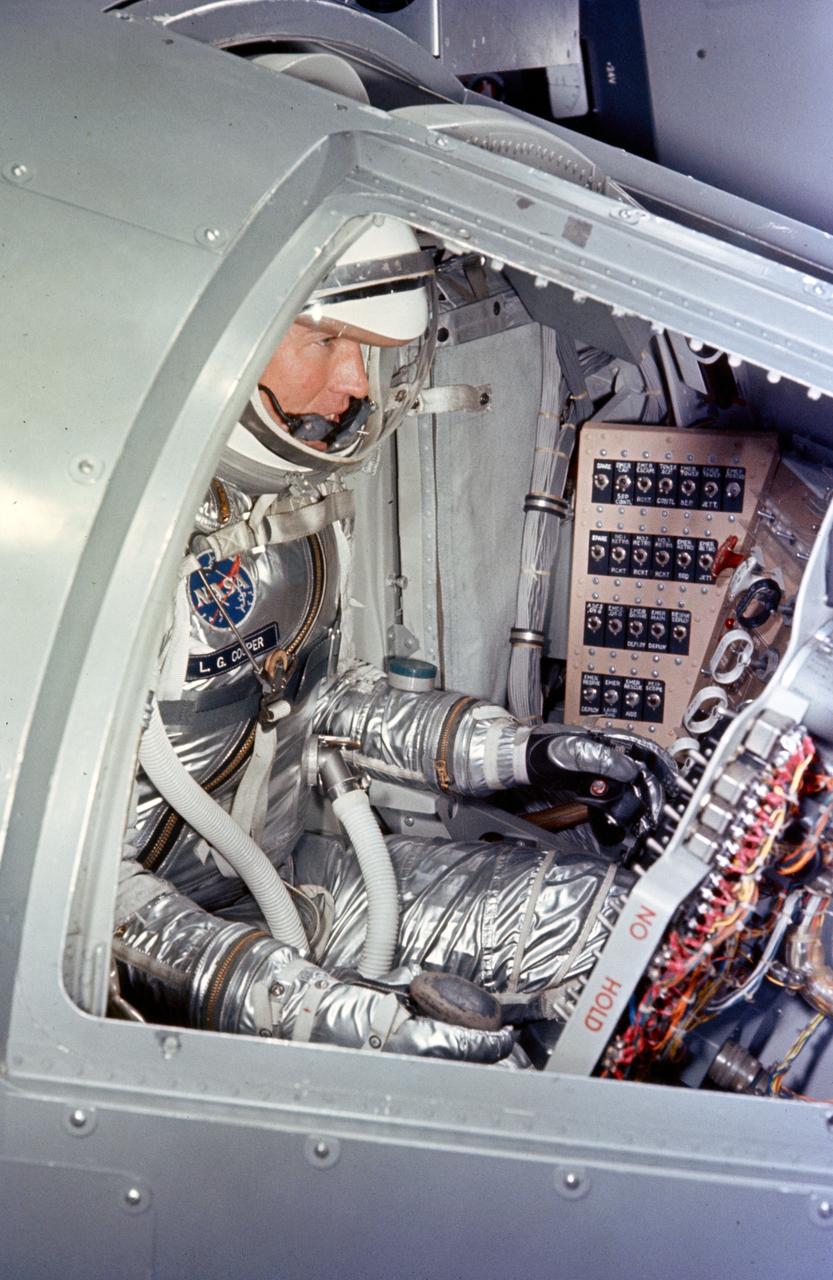
S64-14868 (1963) --- Astronaut L. Gordon Cooper Jr., pilot of the Mercury-Atlas 9 (MA-9) Earth-orbital space mission, participates in preflight simulation training inside his Mercury capsule at Cape Canaveral, Florida. Photo credit: NASA
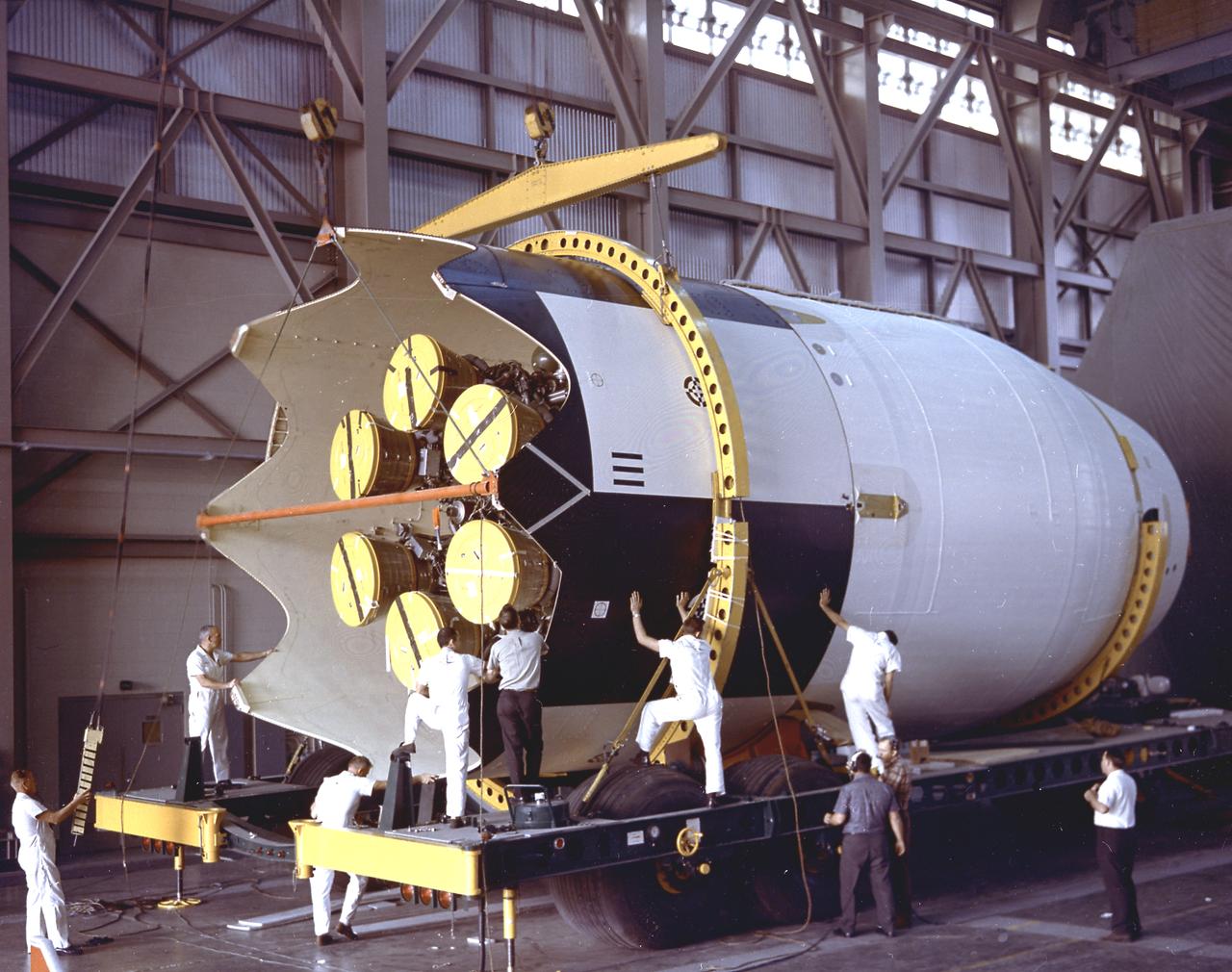
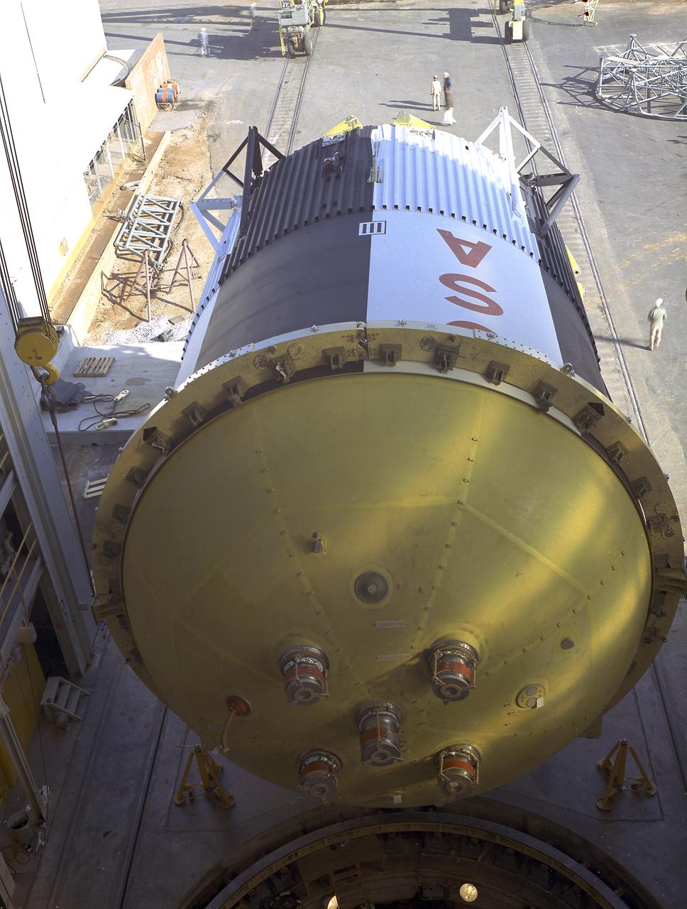
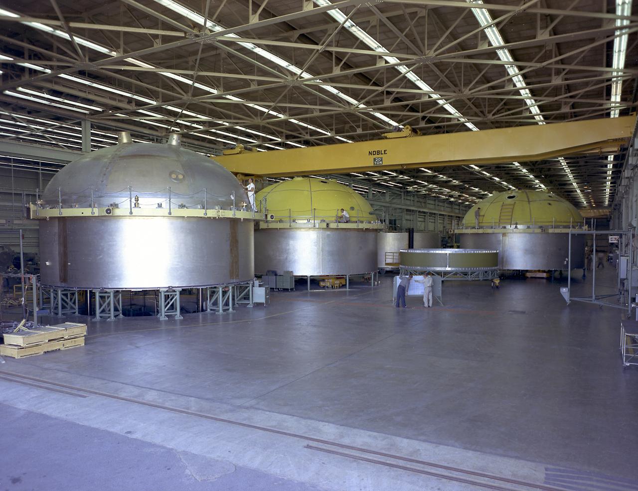
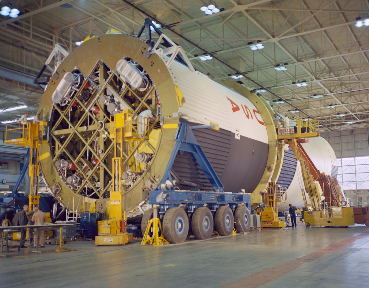
The Saturn I S-IV stage (second stage) assembly for the SA-9 mission underwent the weight and balance test in the hangar building at Cape Canaveral. The S-IV stage had six RL-10 engines which used liquid hydrogen and liquid oxygen as its propellants arranged in a circle. Each RL-10 engine produced a thrust of 15,000 pounds, a total combined thrust of 90,000 pounds. The SA-9 mission was the first Saturn with operational payload Pegasus I, meteoroid detection satellite, and launched on February 16, 1965.

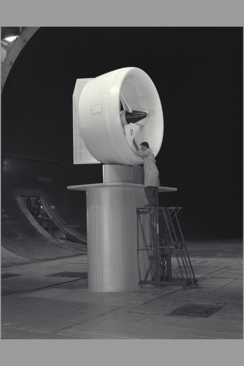
3/4 rear view Ryan XV-5A lift-fan VSTOL airplane. Pictured with Tom Wills.
Overhead view of Ryan XV-5A lift-fan VSTOL airplane.
This image shows the Saturn V S-IC-T stage (S-IC static test article) fuel tank being attached to the thrust structure in the vehicle assembly building at the Marshall Space Flight Center (MSFC). The S-IC stage utilized five F-1 engines that used liquid oxygen and kerosene as propellant and provided a combined thrust of 7,500,000 pounds.
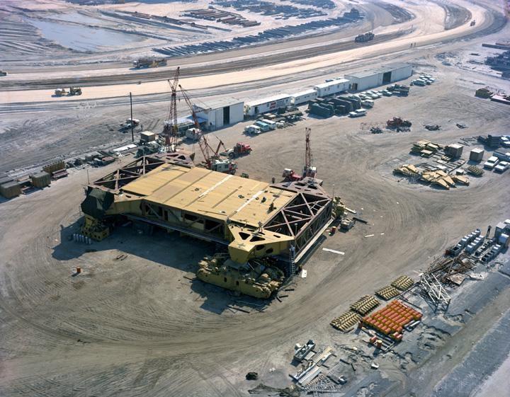
View of CT

S64-31631 (10 Sept. 1964) --- Astronaut Edward H. White II. (EDITOR'S NOTE: Astronaut White died in the Apollo/Saturn 204 fire accident at Cape Kennedy on Jan. 27, 1967.)
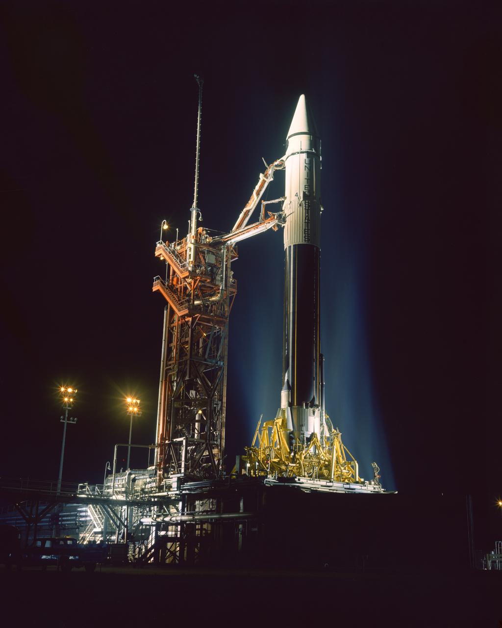
Pre-launch of Centaur 4 A/C 4 from Pad 36A.
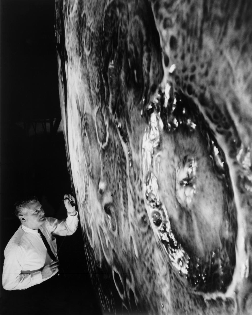
Artists used paintbrushes and airbrushes to recreate the lunar surface on each of the four models comprising the LOLA simulator. Project LOLA or Lunar Orbit and Landing Approach was a simulator built at Langley to study problems related to landing on the lunar surface. It was a complex project that cost nearly $2 million dollars. James Hansen wrote: "This simulator was designed to provide a pilot with a detailed visual encounter with the lunar surface; the machine consisted primarily of a cockpit, a closed-circuit TV system, and four large murals or scale models representing portions of the lunar surface as seen from various altitudes. The pilot in the cockpit moved along a track past these murals which would accustom him to the visual cues for controlling a spacecraft in the vicinity of the moon. Unfortunately, such a simulation--although great fun and quite aesthetic--was not helpful because flight in lunar orbit posed no special problems other than the rendezvous with the LEM, which the device did not simulate. Not long after the end of Apollo, the expensive machine was dismantled." (p. 379) Ellis J. White further described LOLA in his paper "Discussion of Three Typical Langley Research Center Simulation Programs," "Model 1 is a 20-foot-diameter sphere mounted on a rotating base and is scaled 1 in. = 9 miles. Models 2,3, and 4 are approximately 15x40 feet scaled sections of model 1. Model 4 is a scaled-up section of the Crater Alphonsus and the scale is 1 in. = 200 feet. All models are in full relief except the sphere." -- Published in James R. Hansen, Spaceflight Revolution: NASA Langley Research Center From Sputnik to Apollo, (Washington: NASA, 1995), p. 379; From Ellis J. White, "Discussion of Three Typical Langley Research Center Simulation Programs," Paper presented at the Eastern Simulation Council (EAI's Princeton Computation Center), Princeton, NJ, October 20, 1966.
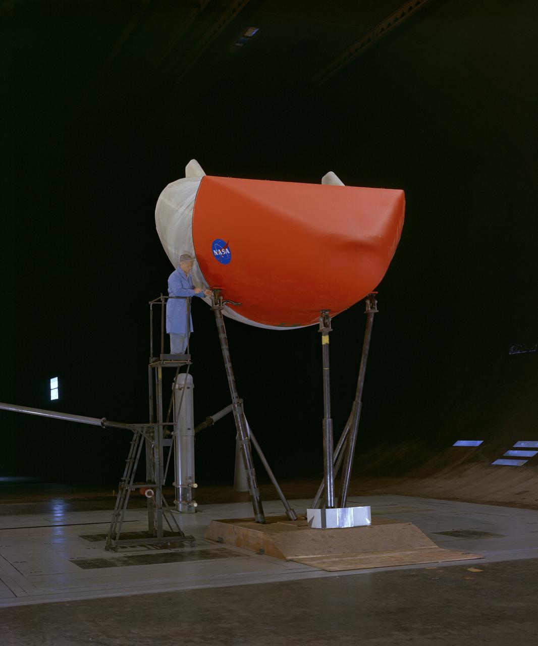
3/4 front view of M-1-L inflatable recovery able lifting body model in Ames 40x80 foot wind tunnel. Mechanic, Ray Schmorance included in picture.

S64-32110 (1964) --- Astronaut Virgil I. (Gus) Grissom
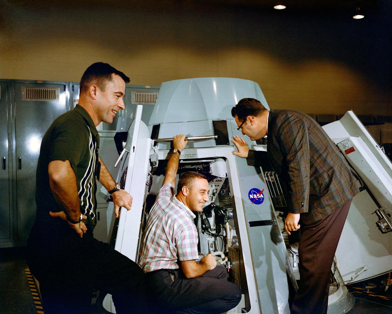
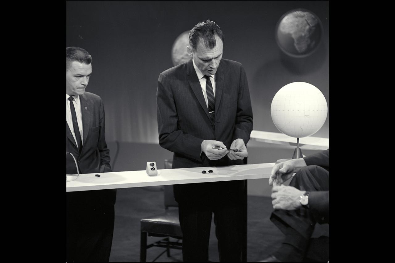
S64-40294 (19 Nov. 1964) --- Astronauts Virgil I. Grissom (center) and John W. Young (left), prime crew for the Gemini-Titan 3 mission, are shown inspecting the inside of Gemini spacecraft at the Mission Control Center at Cape Kennedy, Florida. Riley D. McCafferty is at right. Photo credit: NASA
A researcher fills a small container used to represent a liquid hydrogen tank in preparation for a microgravity test in the 2.2-Second Drop Tower at the National Aeronautics and Space Administration (NASA) Lewis Research Center. For over a decade, NASA Lewis endeavored to make liquid hydrogen a viable propellant. Hydrogen’s light weight and high energy made it very appealing for rocket propulsion. One of the unknowns at the time was the behavior of fluids in the microgravity of space. Rocket designers needed to know where the propellant would be inside the fuel tank in order to pump it to the engine. NASA Lewis utilized sounding rockets, research aircraft, and the 2.2 Second Drop Tower to study liquids in microgravity. The drop tower, originally built as a fuel distillation tower in 1948, descended into a steep ravine. By early 1961 the facility was converted into an eight-floor, 100-foot tower connected to a shop and laboratory space. Small glass tanks, like this one, were installed in experiment carts with cameras to film the liquid’s behavior during freefall. Thousands of drop tower tests in the early 1960s provided an increased understanding of low-gravity processes and phenomena. The tower only afforded a relatively short experiment time but was sufficient enough that the research could be expanded upon using longer duration freefalls on sounding rockets or aircraft. The results of the early experimental fluid studies verified predictions made by Lewis researchers that the total surface energy would be minimized in microgravity.
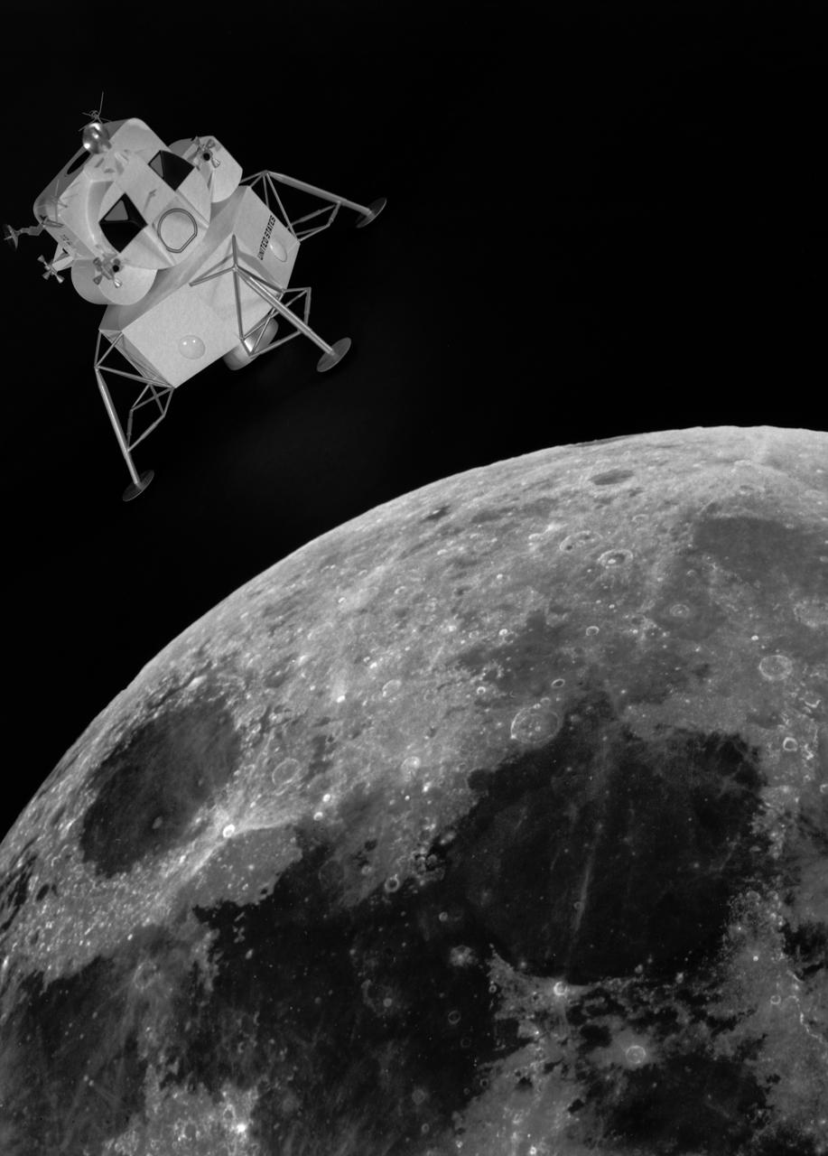
Artist rendering of the lunar excursion module approaching the moon. The lunar module design underwent gradual evolution from the first configuration proposed by Grumman in 1962. This model is a 1964 rendering. Langley had the task of building a simulator for the astronauts to practice lunar landings. The configuration of the initial vehicle used with the Lunar Landing Research Facility (LLRF) was changed in 1967 to more accurately reflect the standing position of the astronauts, cockpit arrangement, instrumentation, controls and field of view.
Pilot Earle Boyer and researcher Henry Brandhorst prepare for a solar cell calibration flight in a Martin B-57B Canberra at the National Aeronautics and Space Administration (NASA) Lewis Research Center. Lewis was in the early stages of decades-long energy conversion and space power research effort. Brandhorst, a member of the Chemistry and Energy Conversion Division, led a team of Lewis researchers in a quest to develop new power sources to sustain spacecraft in orbit. Solar cells proved to be an important source of energy, but researchers discovered that their behavior varied at different atmospheric levels. Their standardization and calibration were critical. Brandhorst initiated a standardized way to calibrate solar cells in the early 1960s using the B-57B aircraft. The pilots would take the aircraft up into the troposphere and open the solar cell to the sunlight. The aircraft would steadily descend while instruments recorded how much energy was being captured by the solar cell. From this data, Brandhorst could determine the estimated power for a particular solar cell at any altitude. Pilot Earle Boyer joined NASA Lewis in October 1962. He had flown Convair F-102 Delta Dagger fighters in the Air Force and served briefly in the National Guard before joining the Langley Research Center. Boyer was only at Langley a few months before he transferred to Cleveland. He flew the B-57B, a Convair F-106 Delta Dart, Gulfstream G-1 with an experimental turboprop, Learjet and many other aircraft over the next 32 years at Lewis.
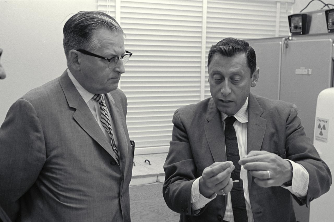
(L) Howard Larson (R) Dr Dean Chapman discuss tektite studies during news conference
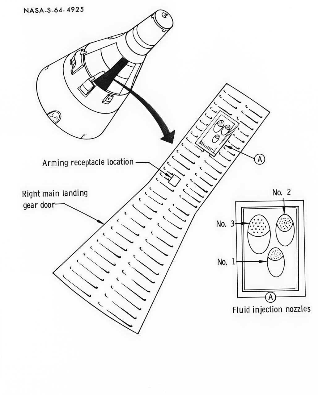
S64-04925 (September 1964) --- Diagram of Gemini spacecraft location of re-entry communications experiment planned for the Gemini-Titan 3 orbital flight.
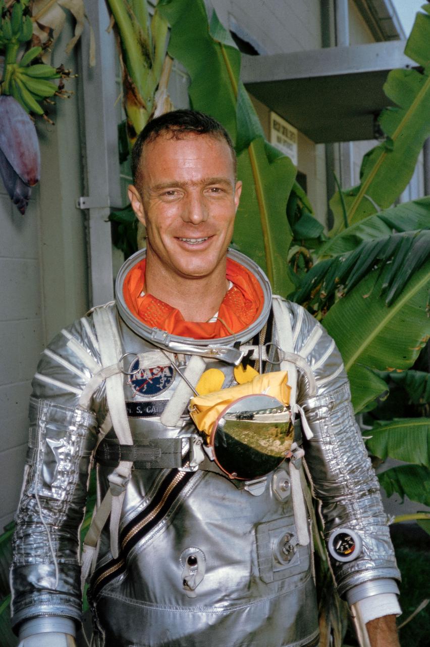
S64-36908 (1962) --- Portrait view of astronaut M. Scott Carpenter, wearing Mercury pressure suit, posing for pictures during astronaut training at the Cape Canaveral, Florida. Photo credit: NASA
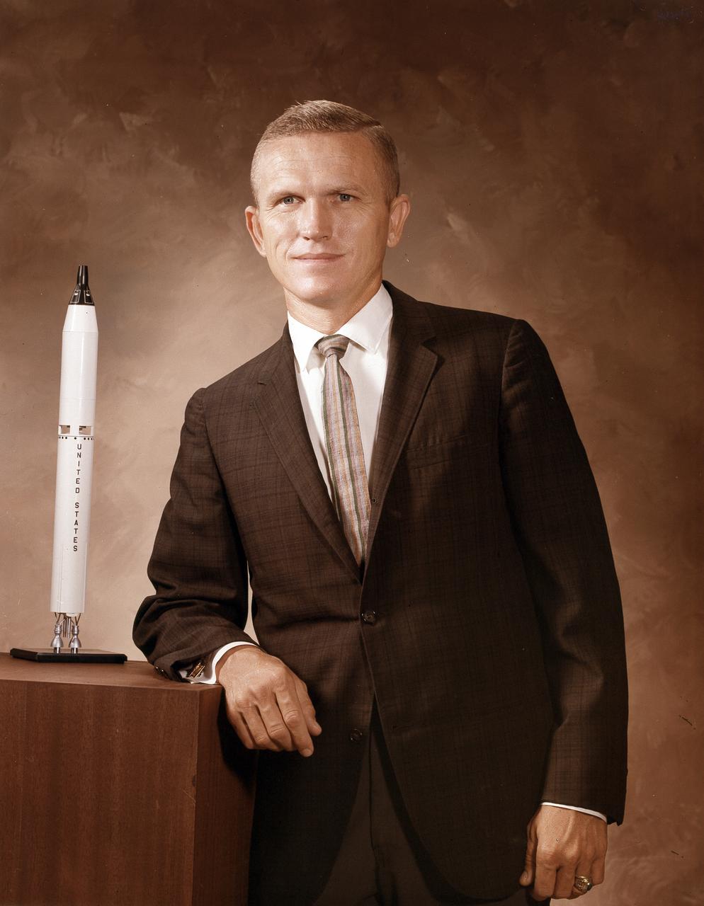
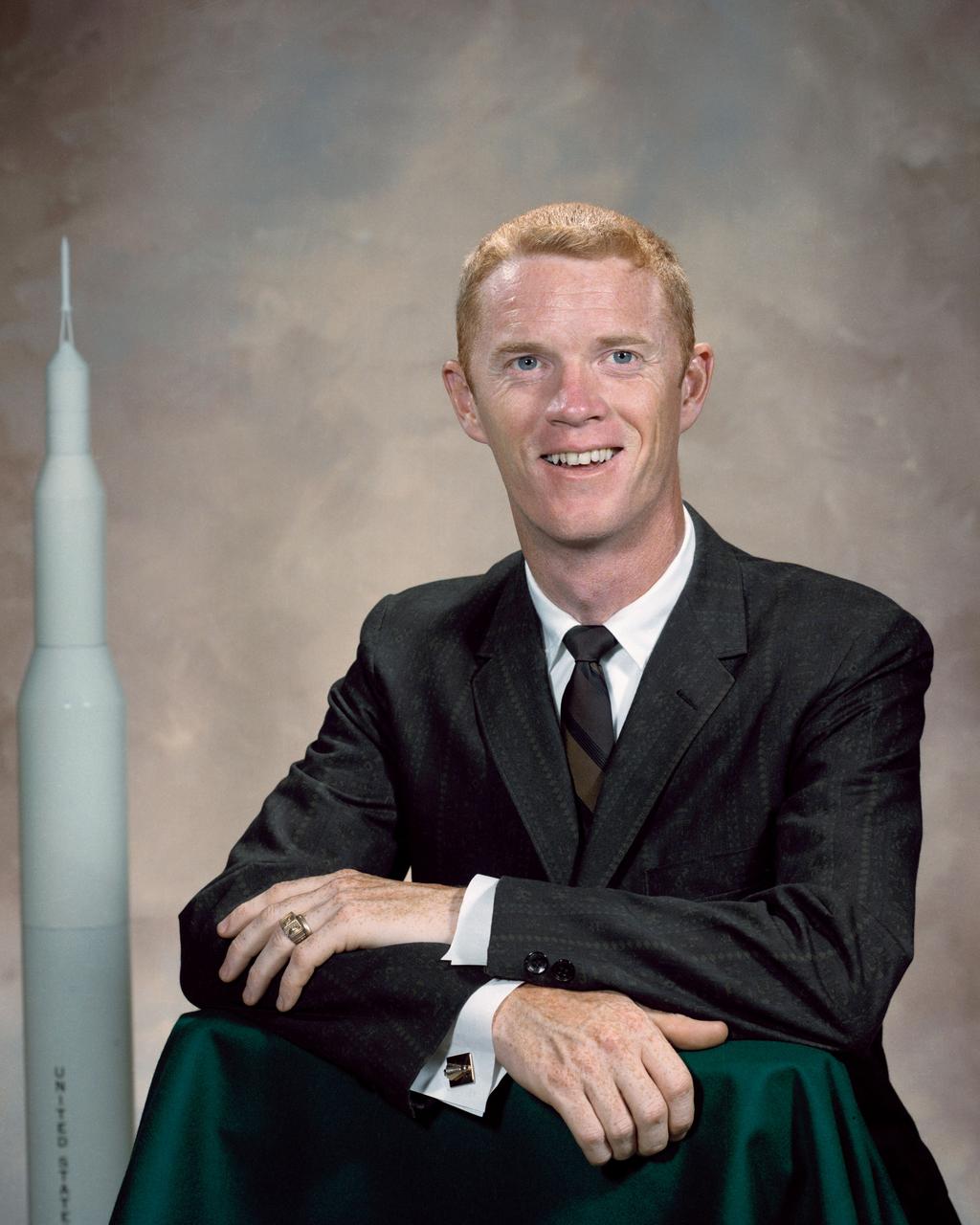
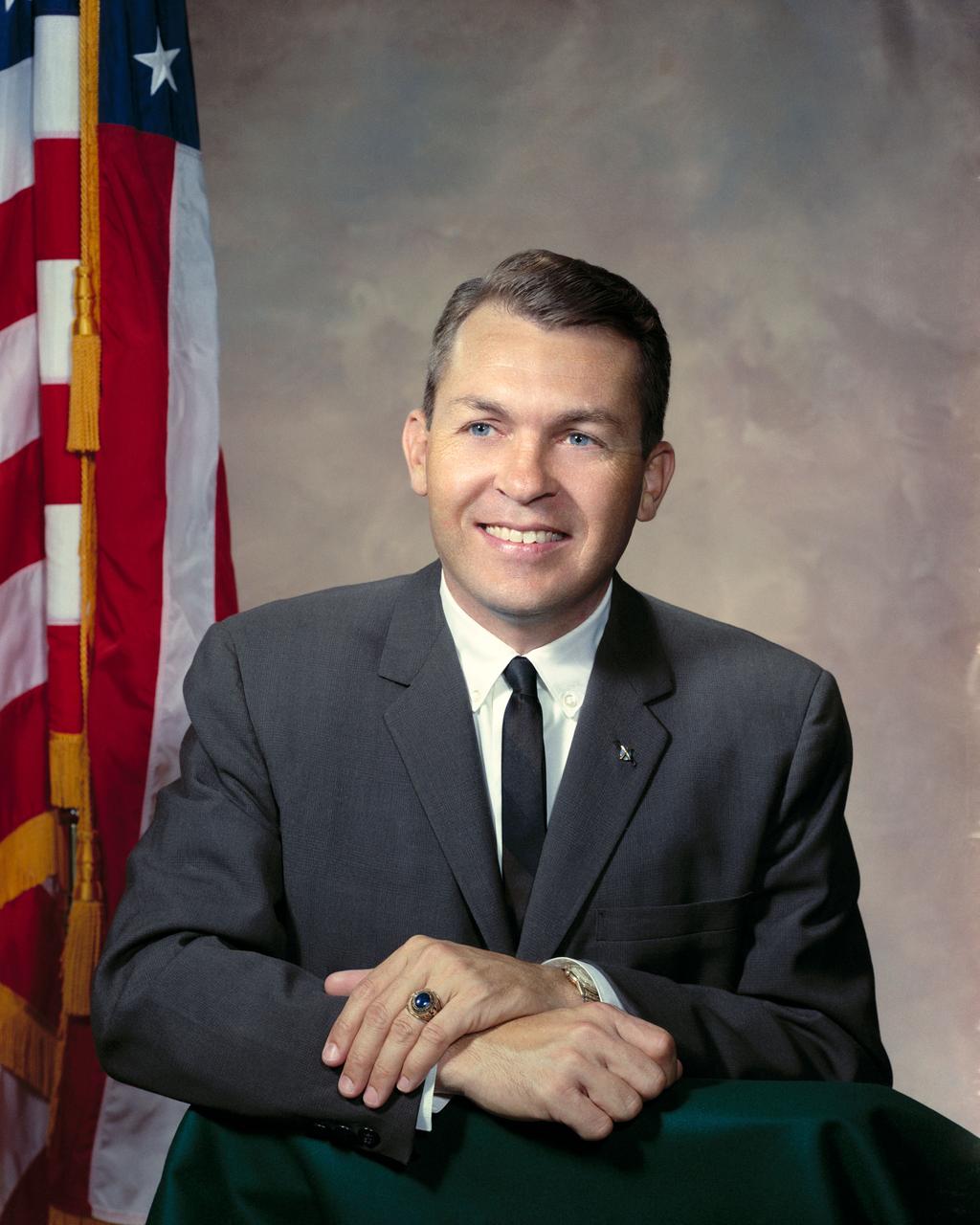
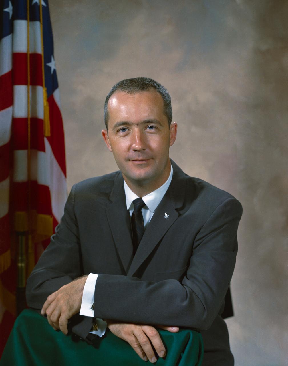
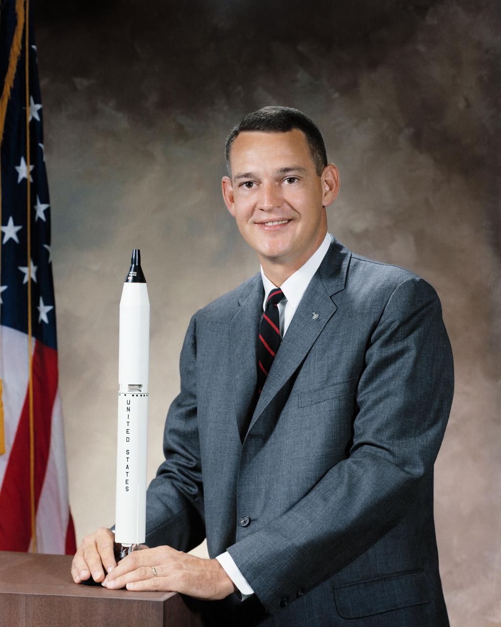
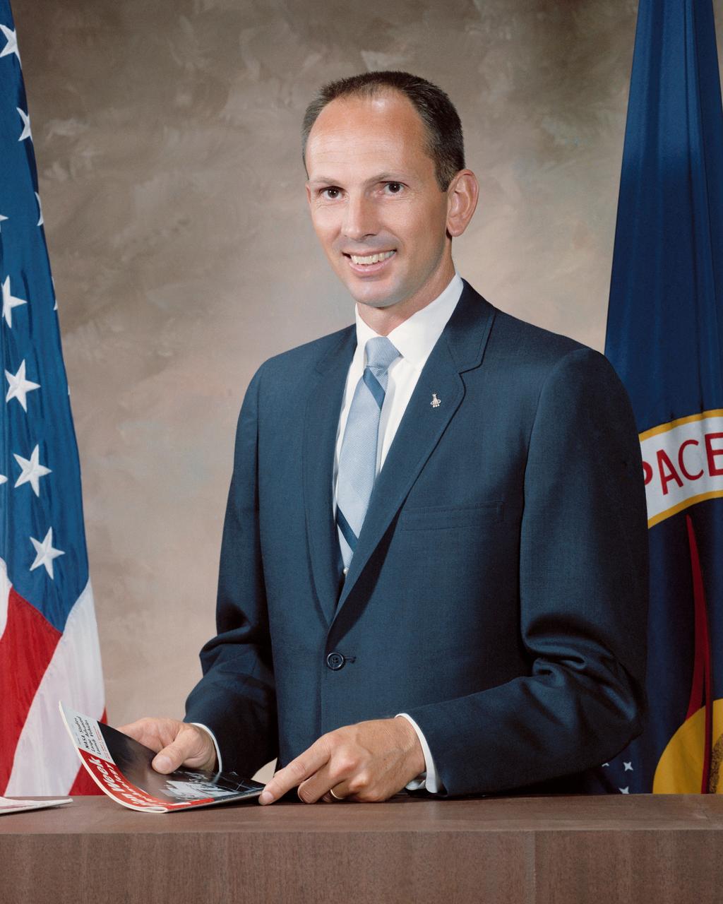
This is the official portrait of astronaut Frank Borman. A career Air Force officer from 1950, his assignments included service as a fighter pilot, an operational pilot and instructor, an experimental test pilot and an assistant professor of thermodynamics and fluid mechanics at West Point. When selected by NASA, Frank Borman was an instructor at the Aerospace Research Pilot School at Edwards AFB, California. In 1967 he served as a member of the Apollo 204 Fire Investigation Board, investigating the causes of the fire which killed three astronauts aboard an Apollo spacecraft. Later he became the Apollo Program Resident Manager, heading the team that reengineered the Apollo spacecraft. He also served as Field Director of the NASA Space Station Task Force. Frank Borman retired from the air Force in 1970, but is well remembered as a part of American history as a pioneer in the exploration of space. He is a veteran of both the Gemini 7, 1965 Space Orbital Rendezvous with Gemini 6 and the first manned lunar orbital mission, Apollo 8, in 1968.
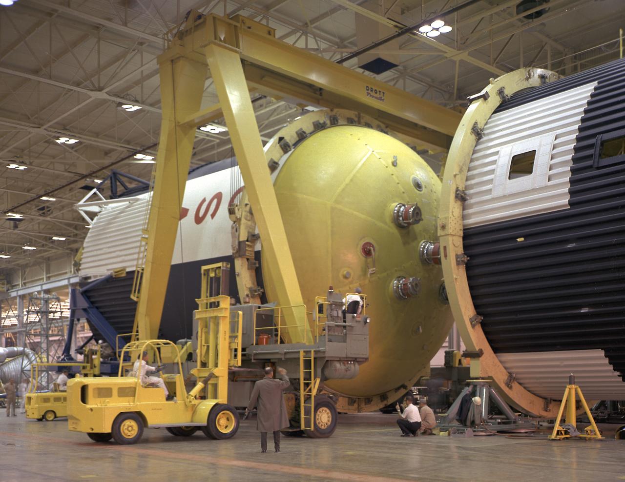
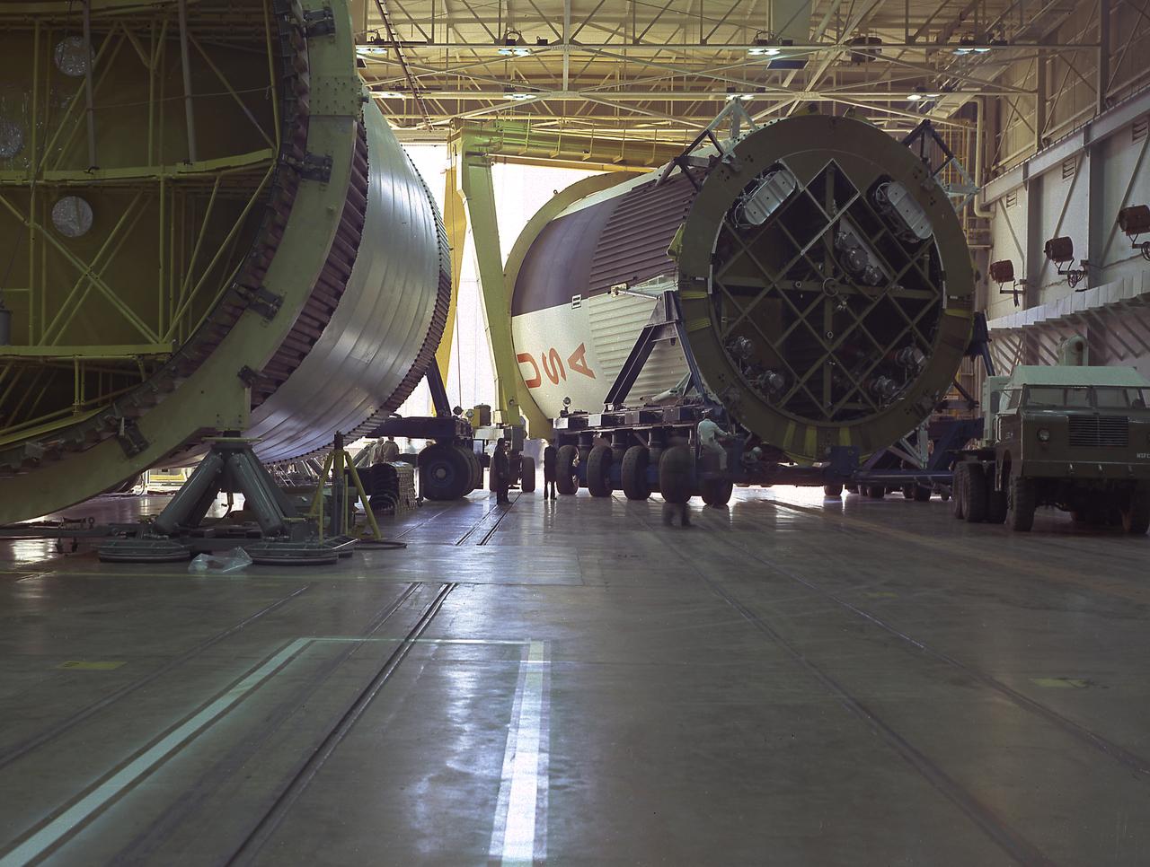
This photograph shows how the fuel tank assembly and the liquid oxygen tank for the Saturn V S-IC (first) stage are placed side by side prior to commencement of the mating of the two stages in the Marshall Space Flight Center, building 4705. The fuel tank carried kerosene as its fuel. The S-IC stage used five F-1 engines, that used kerosene and liquid oxygen as propellant and each engine provided 1,500,000 pounds of thrust. This stage lifted the entire vehicle and Apollo spacecraft from the launch pad.
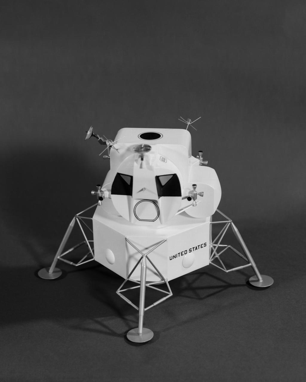
The lunar module design underwent gradual evolution from the first configuration proposed by Grumman in 1962. This model is the 1964 version. Langley had the task of building a simulator for the astronauts to practice lunar landings. The configuration of the initial vehicle used with the Lunar Landing Research Facility (LLRF) was changed in 1967 to more accurately reflect the standing position of the astronauts, cockpit arrangement, instrumentation, controls and field of view.
S64-29936 (10 Sept. 1964) --- Astronaut Russell L. "Rusty" Schweickart, Jr.
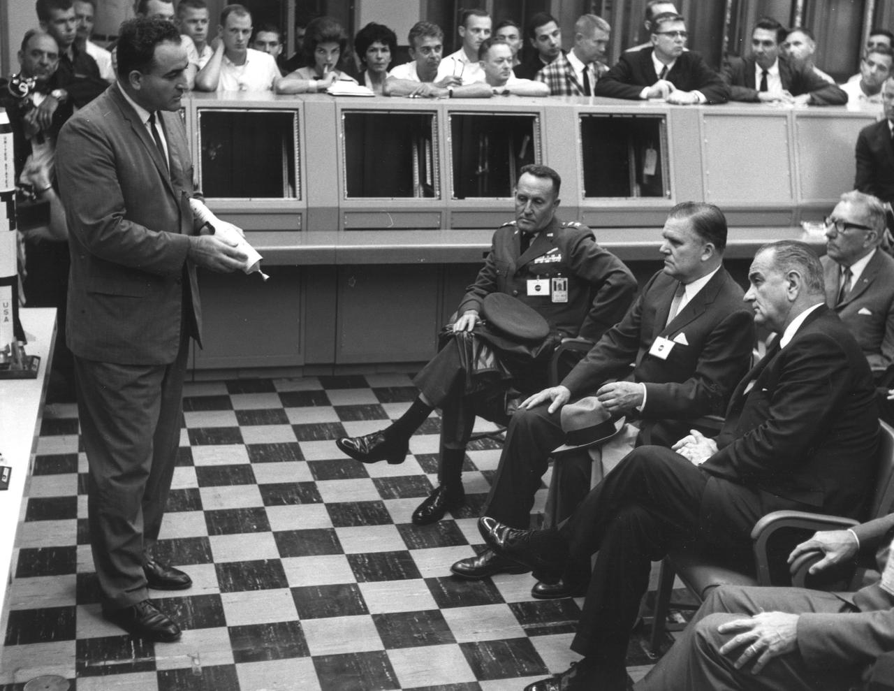
KENNEDY SPACE CENTER, FLA. -- President Lyndon B. Johnson (seated at right), NASA Administrator James T. Webb (seated, center) and Major General Vincent G. Huston (seated, left), commander, Air Force Eastern Test Range, are briefed by Rocco A. Petrone (left), director of Kennedy Space Center Launch Operations, during the Sept. 15, 1964 visit.
Originally the Rendezvous was used by the astronauts preparing for Gemini missions. The Rendezvous Docking Simulator was then modified and used to develop docking techniques for the Apollo program. "The LEM pilot's compartment, with overhead window and the docking ring (idealized since the pilot cannot see it during the maneuvers), is shown docked with the full-scale Apollo Command Module." A.W. Vogeley described the simulator as follows: "The Rendezvous Docking Simulator and also the Lunar Landing Research Facility are both rather large moving-base simulators. It should be noted, however, that neither was built primarily because of its motion characteristics. The main reason they were built was to provide a realistic visual scene. A secondary reason was that they would provide correct angular motion cues (important in control of vehicle short-period motions) even though the linear acceleration cues would be incorrect." -- Published in A.W. Vogeley, "Piloted Space-Flight Simulation at Langley Research Center," Paper presented at the American Society of Mechanical Engineers, 1966 Winter Meeting, New York, NY, November 27 - December 1, 1966;
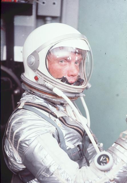
S64-36910 (February 1962) --- Astronaut John H. Glenn Jr., wearing a Mercury pressure suit, was the pilot of the Mercury-Atlas 6 (MA-6) mission. Glenn made America's first manned Earth-orbiting spaceflight on Feb. 20, 1962. This photograph was taken at Cape Canaveral, Florida, during MA-6 preflight training activities. Photo credit: NASA
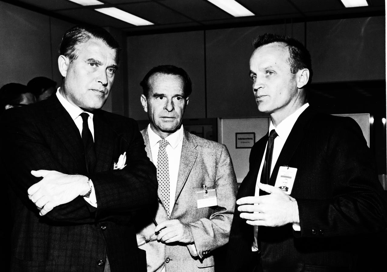
This photograph is dated October 14, 1964, and shows Dr. von Braun, left, during a tour of the NASA Marned Spacecraft Center, now the Johnson Space Center. He is with Dr. J.P. Kuettner, center, from the Marshall Space Flight Center, and Warren J. North from the Manned Spacecraft Center.

S64-12007 (1964) --- Artist concept of Gemini spacecraft and Command Module with two astronauts seated at the controls.

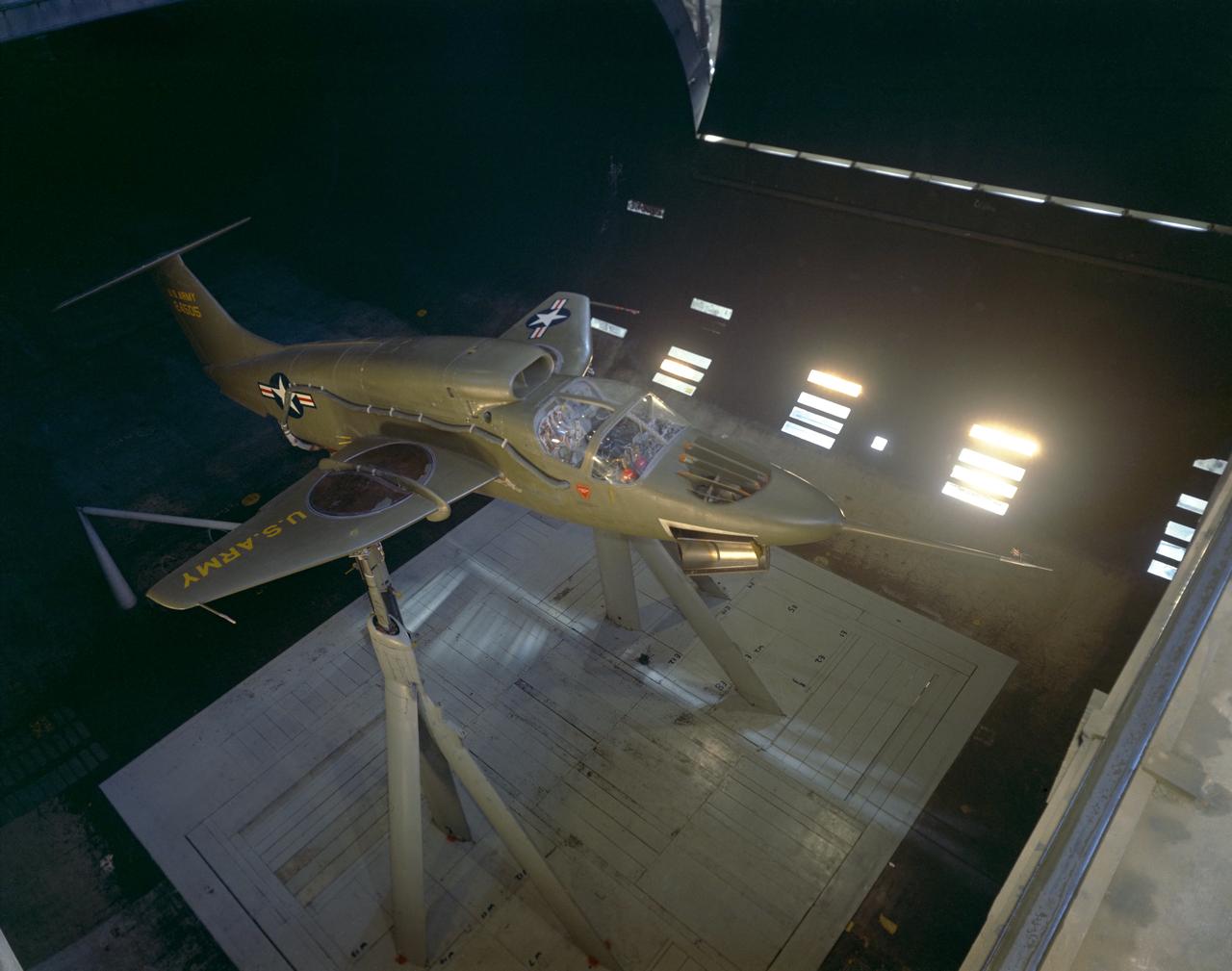
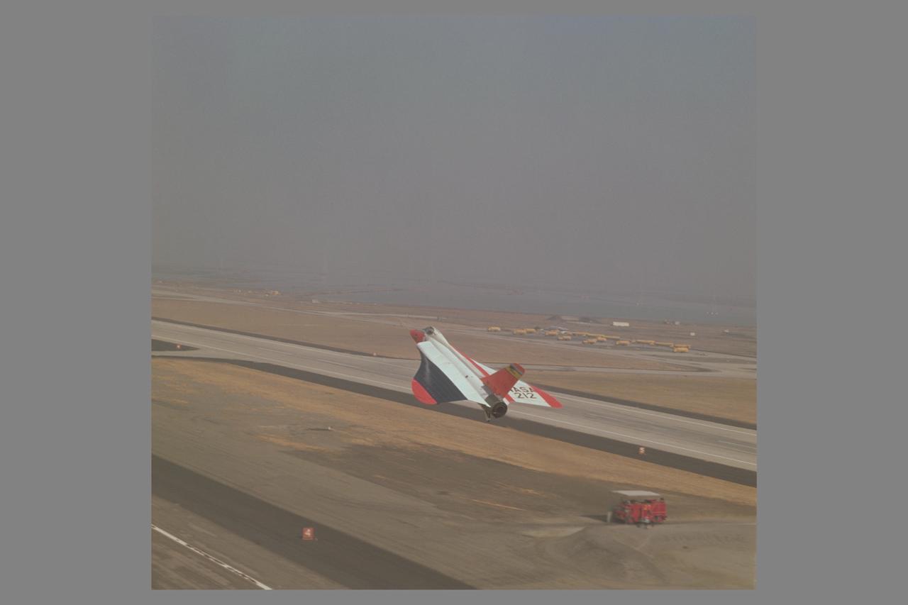
DURING APPROACH. OGEE Wing Planform on modified F5D-1 SkylancerAirplane Flight Tests. 'Flow Visualization Photographs'. In landing approach trials at Moffett Field, vapor trails are generated by low pressure in votex flow near wing leading edge on upper wing surface. Studies were undertaken in efforts to determine if there were adverse effects of vortex flow on the dynamic stability of the aircraft.
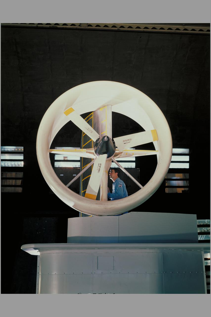
3/4 front view offull scale X-22A ducted fan model. Chuck Greco
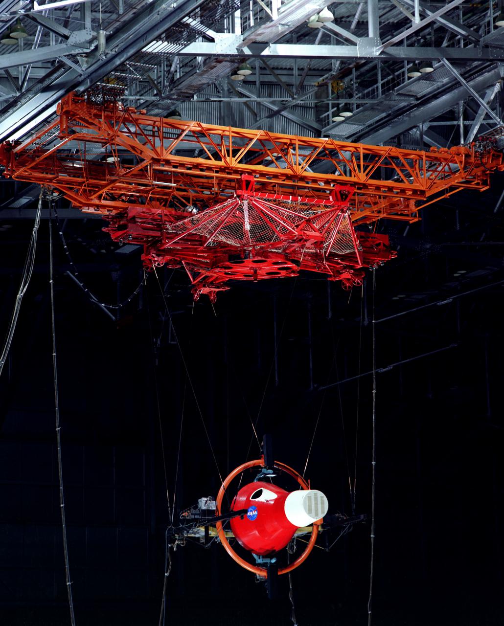
Gemini Rendezvous Docking Simulator suspended from the roof of the Langley Research Center s aircraft hangar. Francis B. Smith wrote: The rendezvous and docking operation of the Gemini spacecraft with the Agena and of the Apollo Command Module with the Lunar Excursion Module have been the subject of simulator studies for several years. This figure illustrates the Gemini-Agena rendezvous docking simulator at Langley. The Gemini spacecraft was supported in a gimbal system by an overhead crane and gantry arrangement which provided 6 degrees of freedom - roll, pitch, yaw, and translation in any direction - all controllable by the astronaut in the spacecraft. Here again the controls fed into a computer which in turn provided an input to the servos driving the spacecraft so that it responded to control motions in a manner which accurately simulated the Gemini spacecraft. -- Published in Barton C. Hacker and James M. Grimwood, On the Shoulders of Titans: A History of Project Gemini, NASA SP-4203 Francis B. Smith, Simulators for Manned Space Research, Paper presented at the 1966 IEEE International convention, March 21-25, 1966.
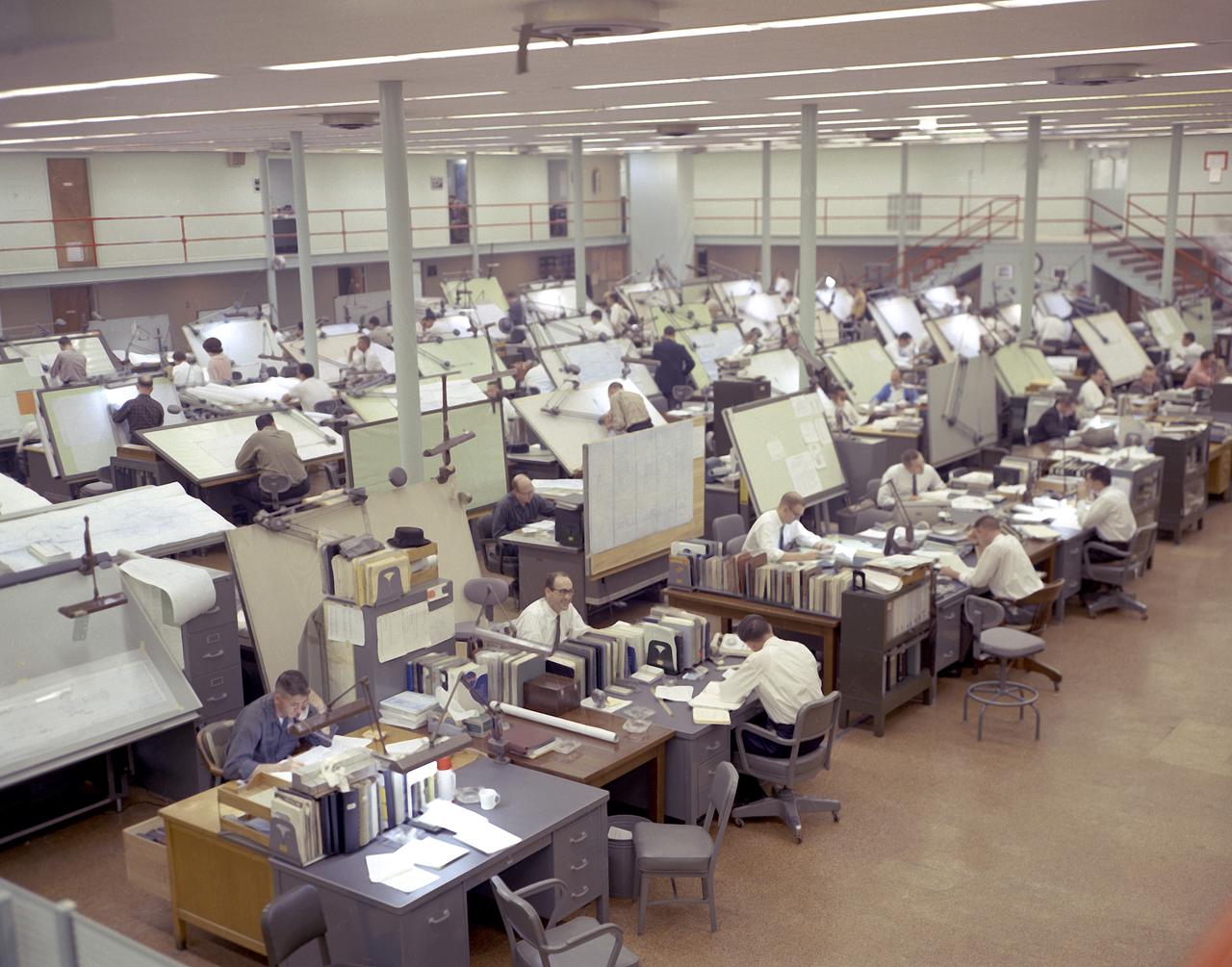
Temporary quarters in the Huntsville Industrial Center (HIC) building located in downtown Huntsville, Alabama, as Marshall Space Flight Center (MSFC) grew. This image shows drafting specialists from the Propulsion and Vehicle Engineering Laboratory at work in the HIC building.
S64-29933 (1964) --- Astronaut Elliot M. See Jr.
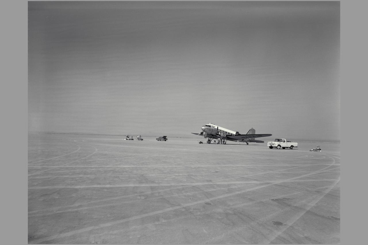
R4D-6 (Bu. No. 99827 NACA 18, NASA 701). TAKE-OFF MONITOR TEST, EDWARDS AIR FORCE BASE. Gunsight Tracking and Guidance and Control Displays. Note: Used in publication in Flight Research at Ames; 57 Years of Development and Validation of Aeronautical Technology NASA SP-1998-3300 fig 76
3/4 front view of full scale X-22A ducted fan model. Chuck Greco
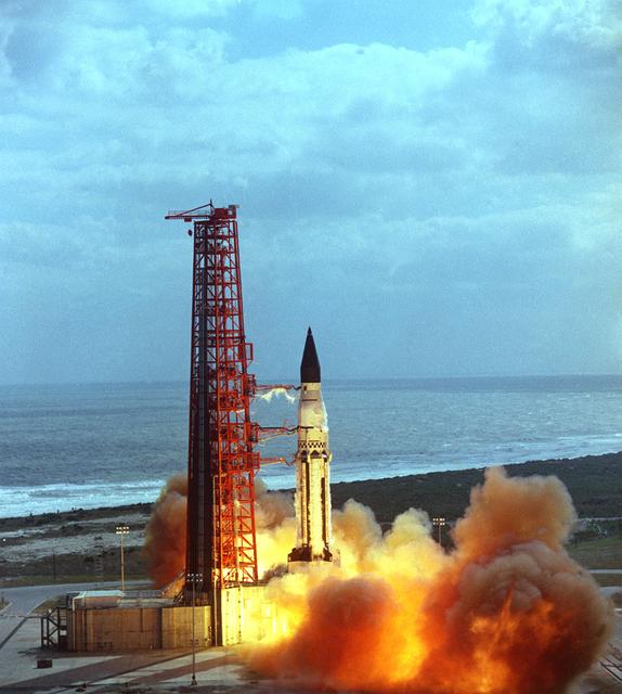
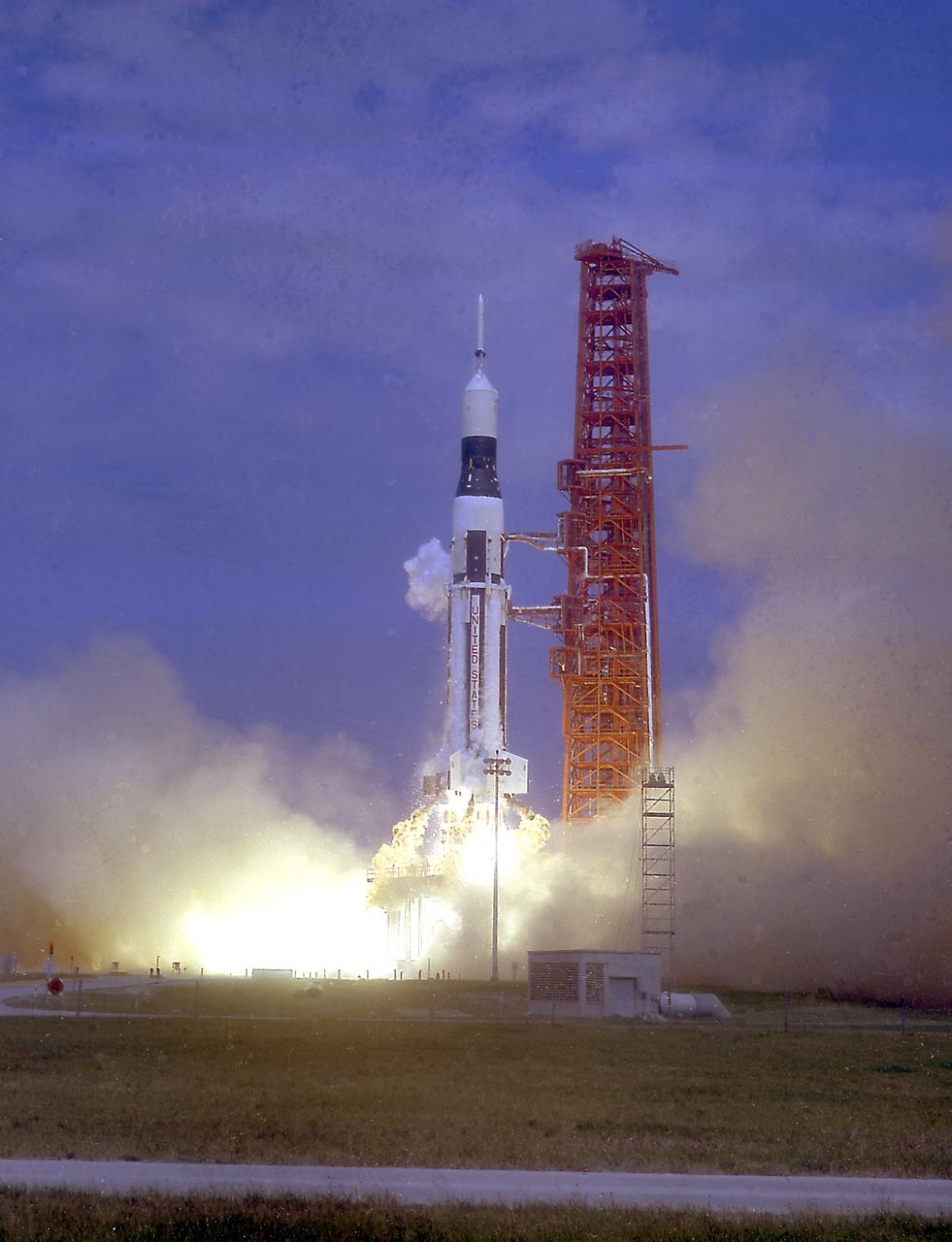
The launch of the SA-5 on January 29, 1964 was the fifth Saturn I launch vehicle. The SA-5 marked a number of firsts in the Marshall Space Flight Center-managed Saturn development program, including the first flight of Saturn I Block II vehicle with eight aerodynamic fins at the bottom of the S-I stage (first stage) for enhanced stability in flight. This also was the first flight of a live S-IV (second or upper) stage with the cluster of six liquid hydrogen-fueled RL-10 engines. the first successful second stage separation, and the first use of the Launch Complex 37.
Centaur A/C 4 in-flight air to air.
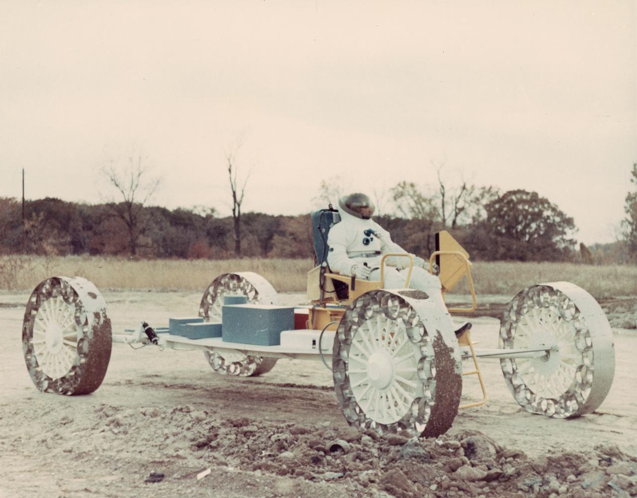
A concept of a possible Lunar Roving Vehicle (LRV) built by the Grumman Industries for NASA’s Marshall Space Flight Center (MSFC), this Mobility Test Article (MTA) is undergoing a full fledged test, complete with space suit attire. The data provided by the MTA helped in designing the LRV, developed under the direction of MSFC. The LRV was designed to allow Apollo astronauts a greater range of mobility during lunar exploration missions.
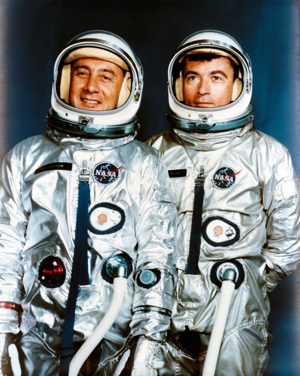
S64-19430 (13 April 1964) --- Astronauts Virgil I. Grissom (left), Gemini-3 command pilot; and John W. Young, pilot. EDITOR?S NOTE: Astronaut Grissom lost his life in the Apollo 1/Saturn 204 fire at Cape Kennedy on Jan. 27, 1967.
The components of the Saturn V booster (S-IC stage) fuel tank are shown in this photograph. The liquid oxygen tank bulkhead on the left and both halves of the fuel tank were in the Marshall Space Flight Center (MSFC) Manufacturing Engineering Laboratory, building 4707. These components were used at MSFC in structural testing to prove that they could withstand the forces to which they were subjected in flight. Each S-IC stage has two tanks, one for kerosene and one for liquid oxygen, made from such components as these. Thirty-three feet in diameter, they hold a total of 4,400,000 pounds of fuel. Although this tankage was assembled at MSFC, the elements were made by the Boeing Company at Wichita and the Michoud Operations at New Orleans.
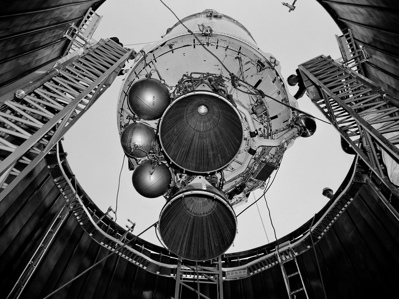
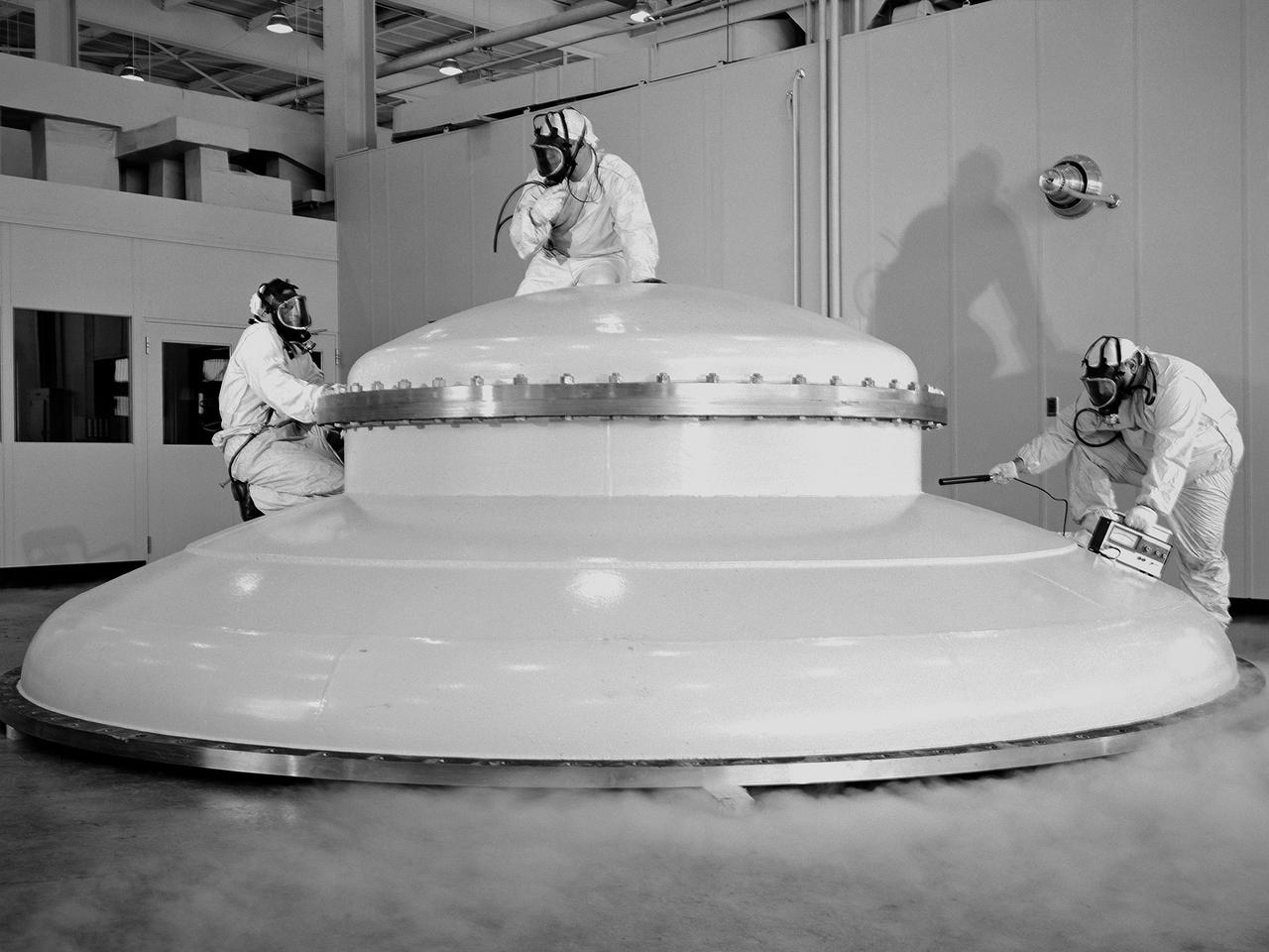
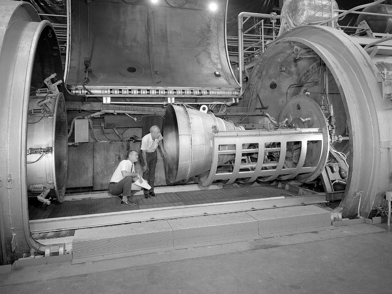
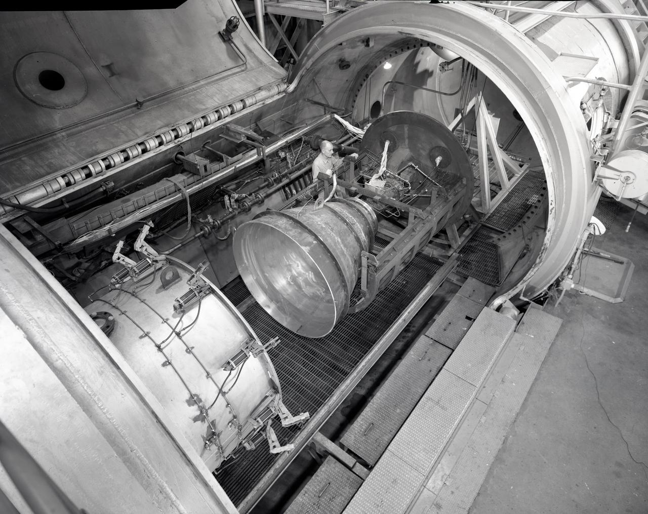
A Centaur second-stage rocket is lowered into the vacuum tank inside the Space Power Chambers at NASA’s Lewis Research Center. Centaur was to be paired with an Atlas booster to send the Surveyor spacecraft to the moon as a precursor to the Apollo landings. Lewis was assigned responsibility for the Centaur Program after the failure of its first developmental flight in May 1962. Lewis’ Altitude Wind Tunnel was converted into two large test chambers—the Space Power Chambers. The facility’s vacuum chamber, seen here, allowed the Centaur to be stood up vertically and subjected to atmospheric conditions-- pressures, temperature, and radiation--similar to those it would encounter in space. The Centaur for these tests was delivered to Cleveland in a C‒130 aircraft on September 27, 1963. The rocket was set up in the facility’s high bay where Lewis technicians and General Dynamics consultants updated its flight systems to match the upcoming Atlas-Centaur‒4 mission. Months were spent reharnessing the Centaur’s electronics, learning about the systems, and being taught how to handle flight hardware. By early spring 1964, the extensive setup of both the spacecraft and the chamber was finally completed. On March 19 the Centaur was rolled out from the shop, hoisted high into the air by a crane, and lowered into the waiting space tank. Researchers were able to verify that the Centaur’s electronics and electrical systems functioned reliably in a space environment.
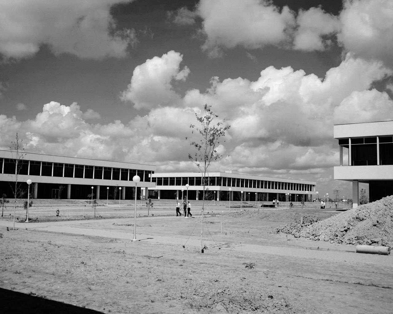
Bldg. 13, left, bldg. 15, right, looking Soutnwest. MSC, HOUSTON, TX B&W
3/4 front view of full scale X-22A ducted fan model. Chuck Greco
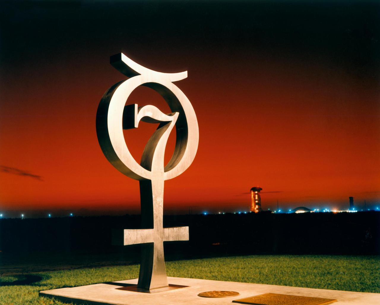
KENNEDY SPACE CENTER, FLA. -- The Mercury monument, honoring the original seven astronauts, is shown here at sunrise at Pad 14.
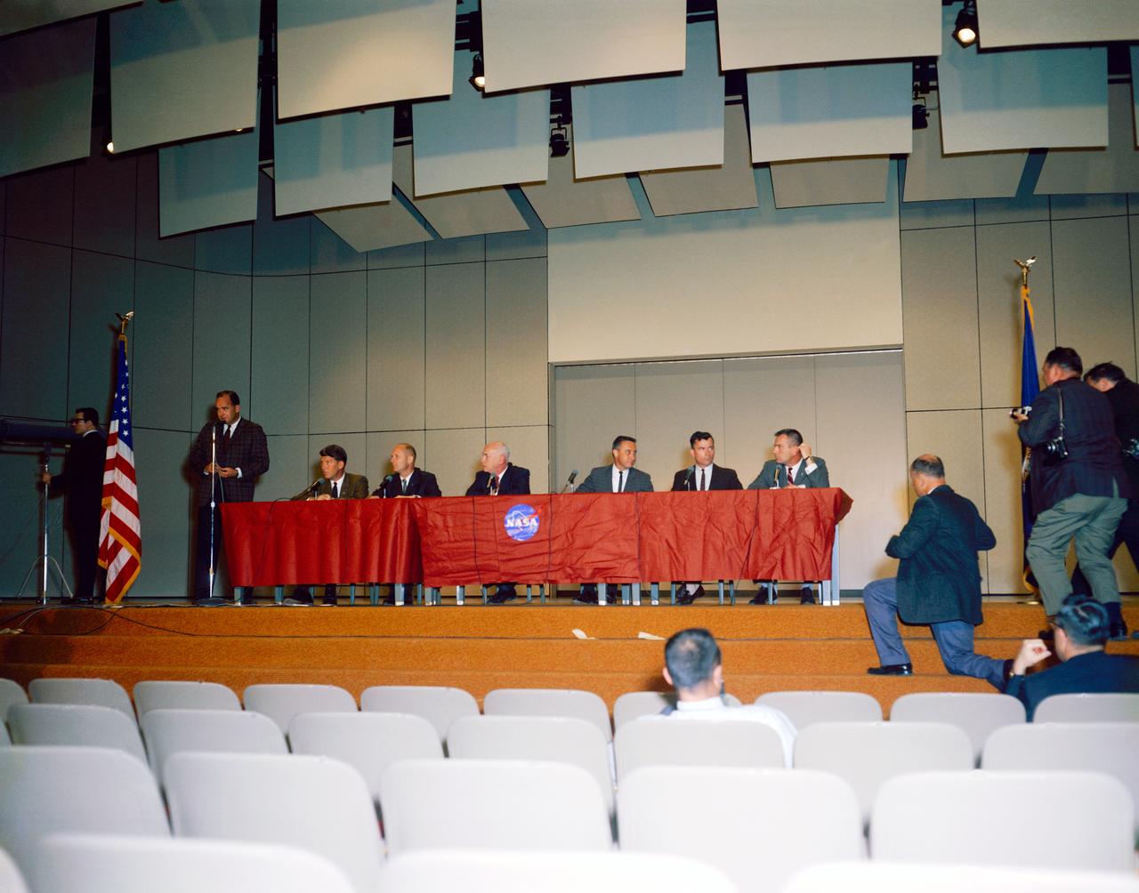
S64-19466 (13 April 1964) --- A press conference was held in the Bldg. 1 auditorium at the NASA Manned Spacecraft Center to announce the first Gemini astronaut selections. Shown left to right are Paul Haney, MSC Public Affairs Officer (standing); astronauts Walter Schirra and Thomas Stafford; Dr. Robert Gilruth, director of MSC; astronauts Virgil Grissom and John Young; and Donald K. Slayton, assistant director of Flight Crew Operations at MSC.
Bill Harrison and Bud Meilander check the setup of an Apollo Contour rocket nozzle in the Propulsion Systems Laboratory at the National Aeronautics and Space Administration (NASA) Lewis Research Center. The Propulsion Systems Laboratory contained two 14-foot diameter test chambers that could simulate conditions found at very high altitudes. The facility was used in the 1960s to study complex rocket engines such as the Pratt and Whitney RL-10 and rocket components such as the Apollo Contour nozzle, seen here. Meilander oversaw the facility’s mechanics and the installation of test articles into the chambers. Harrison was head of the Supersonic Tunnels Branch in the Test Installations Division. Researchers sought to determine the impulse value of the storable propellant mix, classify and improve the internal engine performance, and compare the results with analytical tools. A special setup was installed in the chamber that included a device to measure the thrust load and a calibration stand. Both cylindrical and conical combustion chambers were examined with the conical large area ratio nozzles. In addition, two contour nozzles were tested, one based on the Apollo Service Propulsion System and the other on the Air Force’s Titan transtage engine. Three types of injectors were investigated, including a Lewis-designed model that produced 98-percent efficiency. It was determined that combustion instability did not affect the nozzle performance. Although much valuable information was obtained during the tests, attempts to improve the engine performance were not successful.

S64-31469 (10 Sept. 1964) --- Astronaut Donn F. Eisele.

This is a photograph that was made on October 14, 1964 of Dr. von Braun while he toured the Marned Spacecraft Center, now the Johnson Space Center in Houston, Texas. He is shown inspecting a Gemini-Agena Docking Simulator.
S64-31852 (10 Sept. 1964) --- Astronaut James A. McDivitt
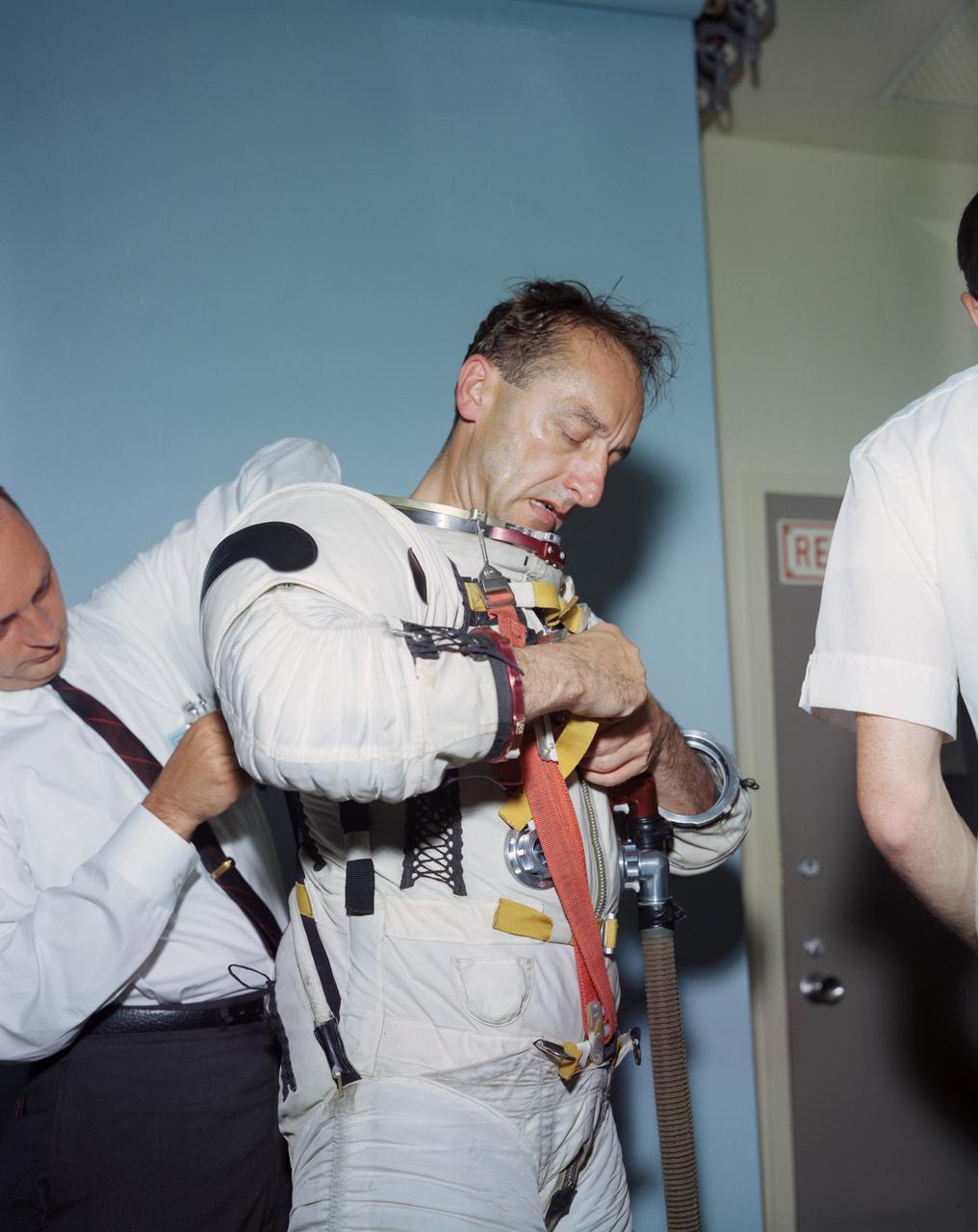
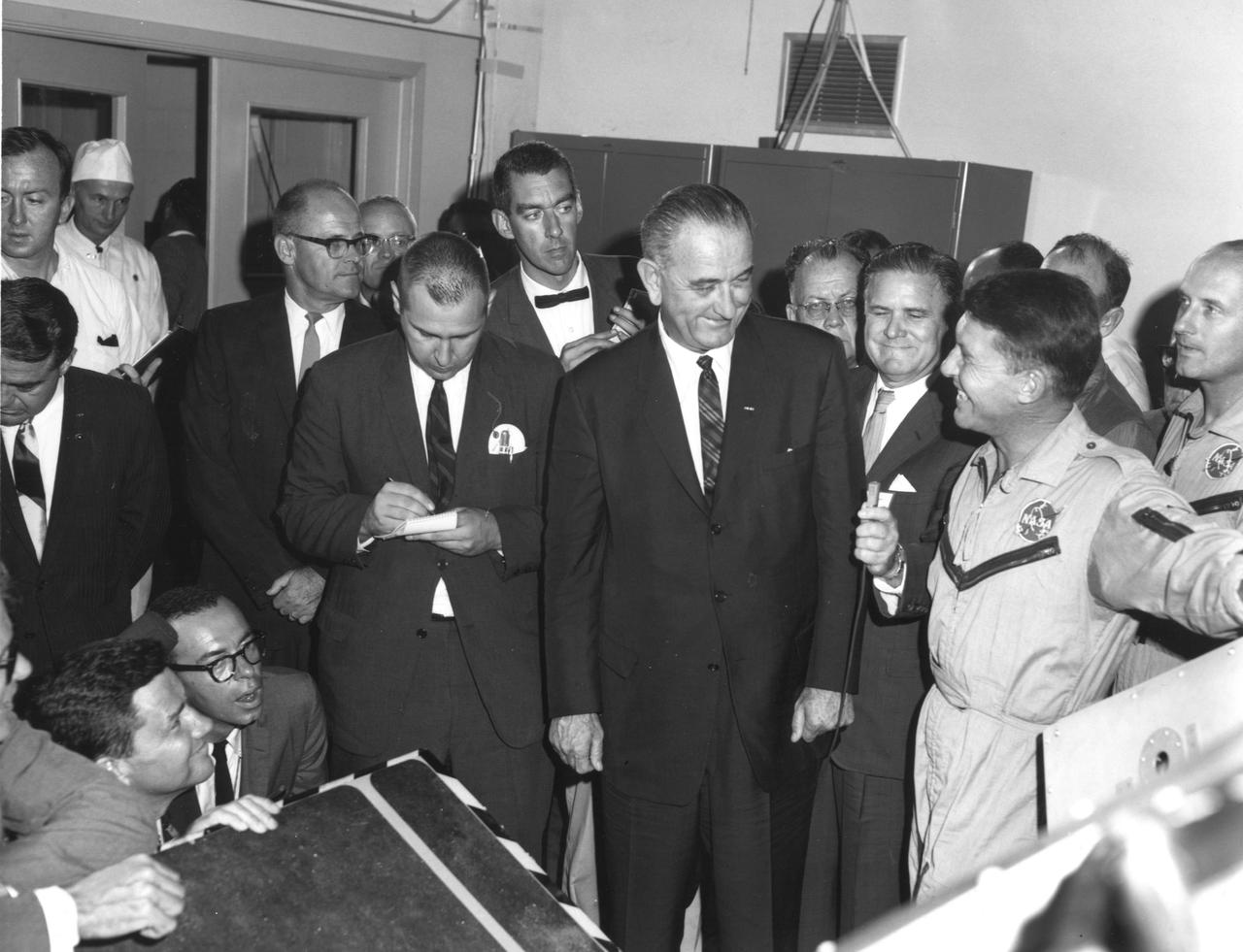
S64-27314 (1964) --- Dr. Mueller & General Funk trying on Apollo & Gemini suits. - Complete Caption Pending

Dr. von Braun became Director of the NASA Marshall Space Flight Center on July 1, 1960.
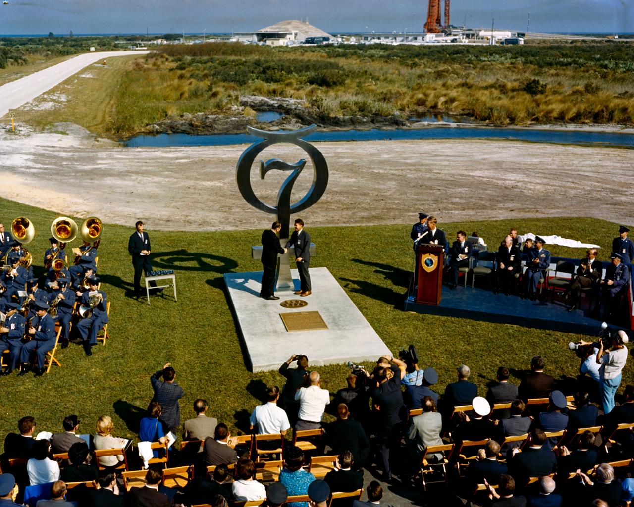
S64-40111 (1964) --- Wide angle view of the Mercury 7 memorial dedication. Photo credit: NASA
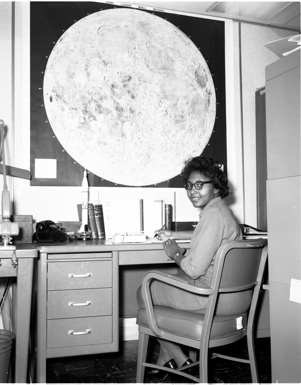
Jeanette Scissum joined NASA’s Marshall Space Flight Center in 1964 after earning bachelor's and master's degrees in mathematics from Alabama A&M University. Scissum published a NASA report in 1967, “Survey of Solar Cycle Prediction Models,” which put forward techniques for improved forecasting of the sunspot cycle. In the mid-1970s she worked as a space scientist in the Space Environment Branch of Marshall’s Space Sciences Laboratory and later led activities in Marshall’s Atmospheric, Magnetospheric, and Plasmas in Space project.In 1975, Scissum wrote an article for the National Technical Association, “Equal Employment Opportunity and the Supervisor – A Counselor’s View,” which argued that many discrimination complaints could be avoided “through adequate and meaningful communication.” Scissum later worked at NASA Headquarters as a computer systems analyst responsible for analyzing and directing NASA management information and technical support systems.
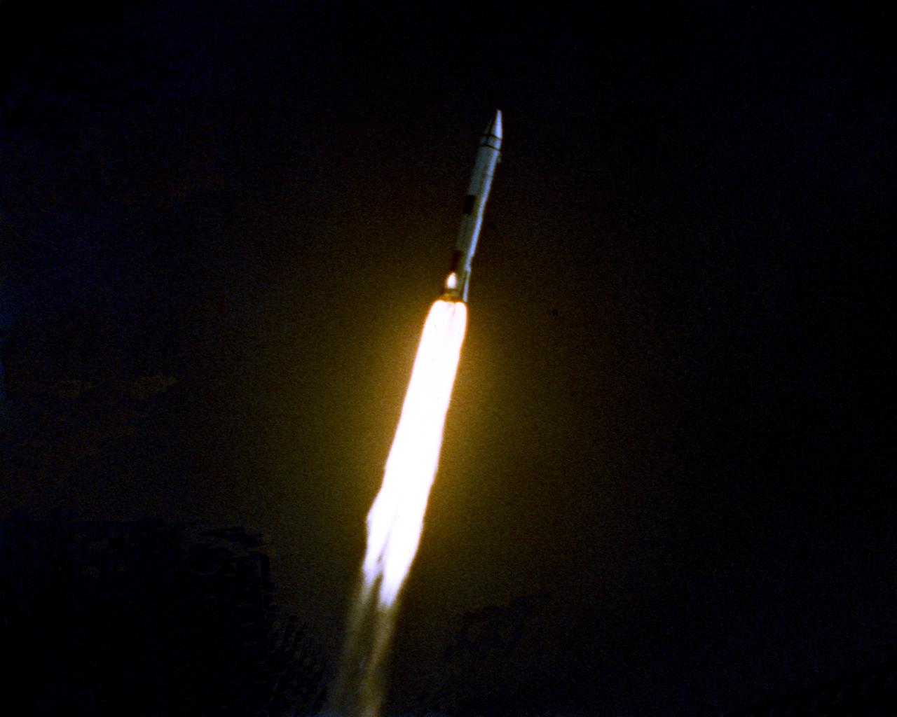
The launch of the SA-7 (Saturn I Block II) was on September 18, 1964. The SA-7 mission was the second orbital flight of the S-IV stage (second stage) with the payload consisting of the Apollo command and service module's instrument unit. The Saturn I Block II vehicle had two live stages, and were basically in the two-stage configuration of the Saturn I vehicle. While the tank arrangement and the engine patterns were the same, there were marked changes between the Block I and II versions. The first stage (S-I stage) was an improved version of the Block I S-I stage. The Block II S-1 stage had eight fins added for greater aerodynamic stability in the lower atmosphere.
3/4 front view Ryan XV-5A lift-fan VSTOL airplane. Pictured with Tom Wills.
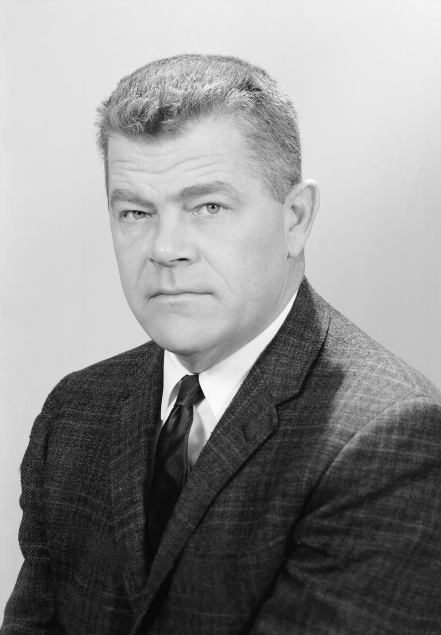
Portrait of Author W. Vogeley
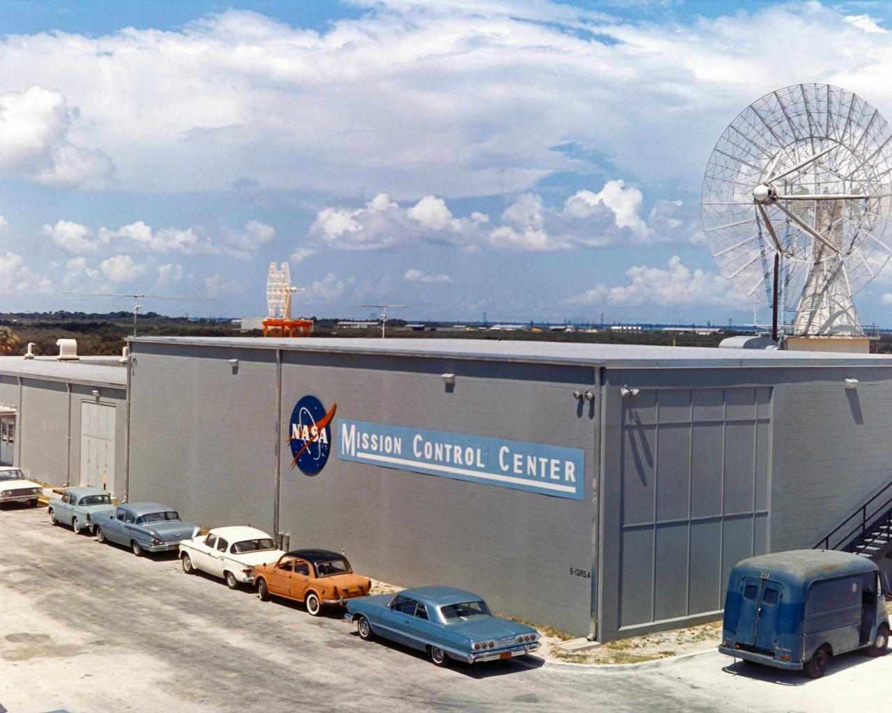
CAPE CANAVERAL, Fla. - Renamed the Mission Control Center, the facility continued to be the flight control through the first three missions of Project Gemini. The Mercury Mission Control Center in Florida played a key role in the United States' early spaceflight program. Located at Cape Canaveral Air Force Station, the original part of the building was constructed between 1956 and 1958, with additions in 1959 and 1963. The facility officially was transferred to NASA on Dec. 26, 1963, and served as mission control during all the Project Mercury missions, as well as the first three flights of the Gemini Program, when it was renamed Mission Control Center. With its operational days behind, on June 1, 1967, the Mission Control Center became a stop on the public tour of NASA facilities until the mid-90s. In 1999, much of the equipment and furnishings from the Flight Control Area were moved to the Kennedy Space Center Visitor Complex where they became part of the exhibit there. The building was demolished in spring 2010. Photo credit: NASA
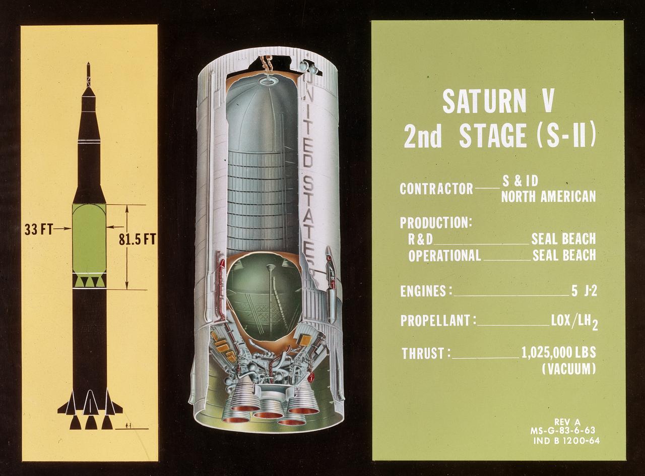
This illustration, with callouts, is of the Saturn V SII (2nd Stage) developed by the Space Division of North American Aviation under the direction of the Marshall Space Flight Center. The 82-foot-long and 33-foot-diameter S-II stage utilized five J-2 engines, each with a 200,000-pound thrust capability. The engine used liquid oxygen and liquid hydrogen as its propellants.
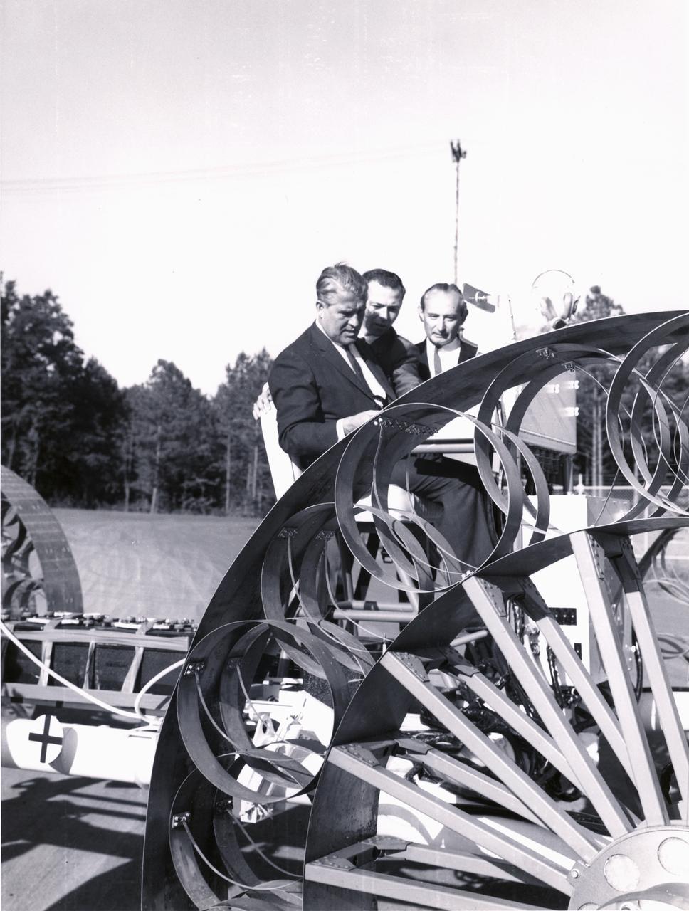
Marshall Space Flight Center (MSFC) director, Wernher von Braun, and others examine one concept of a possible Lunar Roving Vehicle (LRV) built by the Bendix Corporation. The data provided by the MTA helped in designing the LRV, developed under the direction of MSFC. The LRV was designed to allow Apollo astronauts a greater range of mobility during lunar exploration missions.
ON LANDING. OGEE Wing Plan Form on F5D-1 Airplane FLight Tests. 'Flow Visualization Photographs'.
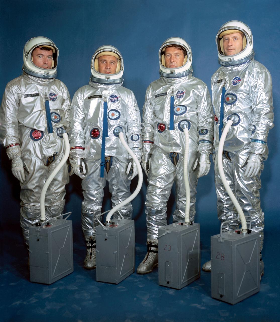
S64-19432 (13 April 1964) --- Left to right are astronauts John W. Young, Virgil I. Grissom, Walter M. Schirra Jr. and Thomas P. Stafford. Gemini III crew assignments are as follows: Grissom, command pilot; Young, pilot, on the prime crew, with Schirra (command pilot) and Stafford (pilot) serving as alternates. EDITOR'S NOTE: For the Gemini-Titan VI mission, Grissom and Young served as backups for Schirra and Stafford.
APOLLO CONTOUR ENGINE MOUNTED IN THE PROPULSION SYSTEMS LABORATORY PSL NO. 2 TEST CELL
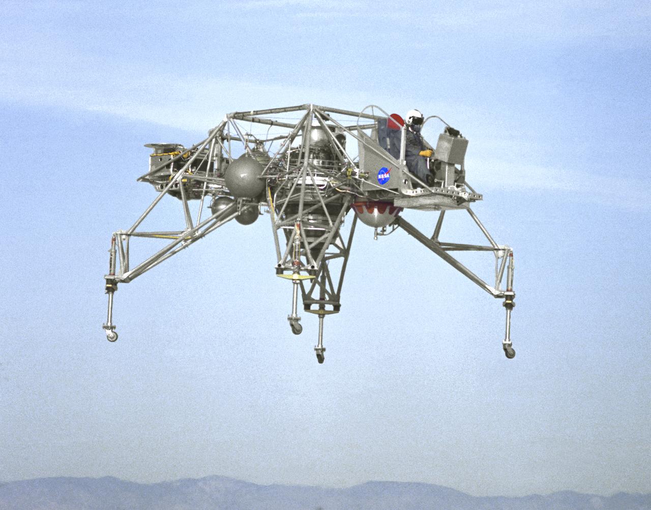
In this NASA Flight Reserch Center photograph the Lunar Landing Research Vehicle (LLRV) number 1 is shown in flight. When Apollo planning was underway in 1960, NASA was looking for a simulator to profile the descent to the Moon's surface. Three concepts surfaced: an electronic simulator, a tethered device, and the ambitious Dryden contribution, a free-flying vehicle. All three became serious projects, but eventually the NASA Flight Research Center's (FRC) Landing Research Vehicle (LLRV) became the most significant one. Hubert M. Drake is credited with originating the idea, while Donald Bellman and Gene Matranga were senior engineers on the project, with Bellman, the project manager. Simultaneously, and independently, Bell Aerosystems Company, Buffalo, N.Y., a company with experience in vertical takeoff and landing (VTOL) aircraft, had conceived a similar free-flying simulator and proposed their concept to NASA headquarters. NASA Headquarters put FRC and Bell together to collaborate. The challenge was; to allow a pilot to make a vertical landing on Earth in a simulated Moon environment, one sixth of the Earth's gravity and with totally transparent aerodynamic forces in a "free flight" vehicle with no tether forces acting on it. Built of tubular aluminum like a giant four-legged bedstead, the vehicle was to simulate a lunar landing profile from around 1500 feet to the Moon's surface. To do this, the LLRV had a General Electric CF-700-2V turbofan engine mounted vertically in gimbals, with 4200 pounds of thrust. The engine, using JP-4 fuel, got the vehicle up to the test altitude and was then throttled back to support five-sixths of the vehicle's weight, simulating the reduced gravity of the Moon. Two hydrogen-peroxide lift rockets with thrust that could be varied from 100 to 500 pounds handled the LLRV's rate of descent and horizontal translations. Sixteen smaller hydrogen-peroxide rockets, mounted in pairs, gave the pilot control in pitch, yaw, and roll. On the LLRV,
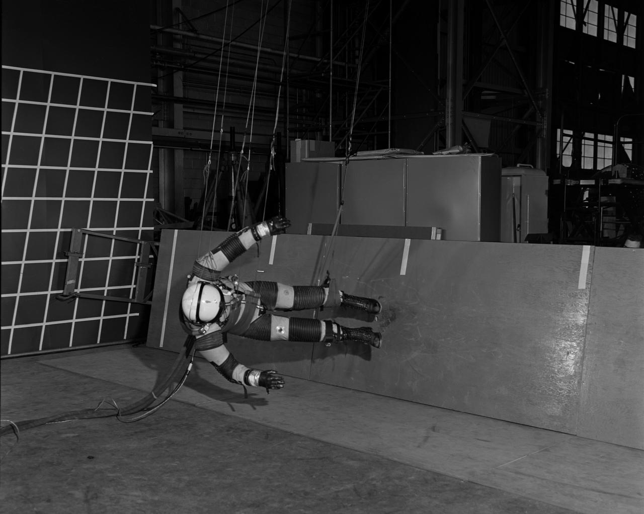
A "suited" test subject on the Reduced Gravity Walking Simulator located in the hangar at Langley Research Center. The initial version of this simulator was located inside the hangar. Later a larger version would be located at the Lunar Landing Facility. The purpose of this simulator was to study the subject while walking, jumping or running. Researchers conducted studies of various factors such as fatigue limit, energy expenditure, and speed of locomotion. Francis B. Smith wrote in "Simulators For Manned Space Research:" "The cables which support the astronaut are supported by an overhead trolley about 150 feet above the center line of the walkway and the support is arranged so that the subject is free to walk, run, jump, and perform other self-locomotive tasks in a more-or-less normal manner, even though he is constrained to move in one place." "The studies thus far show that an astronaut should have no particular difficulty in walking in a pressurized space suit on a hard lunar surface. Rather, the pace was faster and the suit was found to be more comfortable and less fatiguing under lunar "g" than under earth "g." When the test subject wished to travel hurriedly any appreciable distance, a long loping gait at about 10 feet per second was found to be most comfortable." -- Published in James R. Hansen, Spaceflight Revolution: NASA Langley Research Center From Sputnik to Apollo, (Washington: NASA, 1995), p. 377; Francis B. Smith, "Simulators For Manned Space Research," Paper for 1966 IEEE International Convention, New York, NY, March 21-25, 1966.
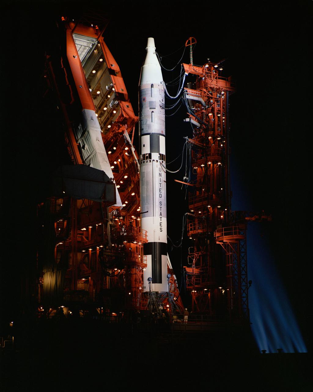
S64-13534 (1964) --- View of a Gemini-Titan spacecraft on launch pad at night. The launch pad lights are all on and there are spotlights in the background.
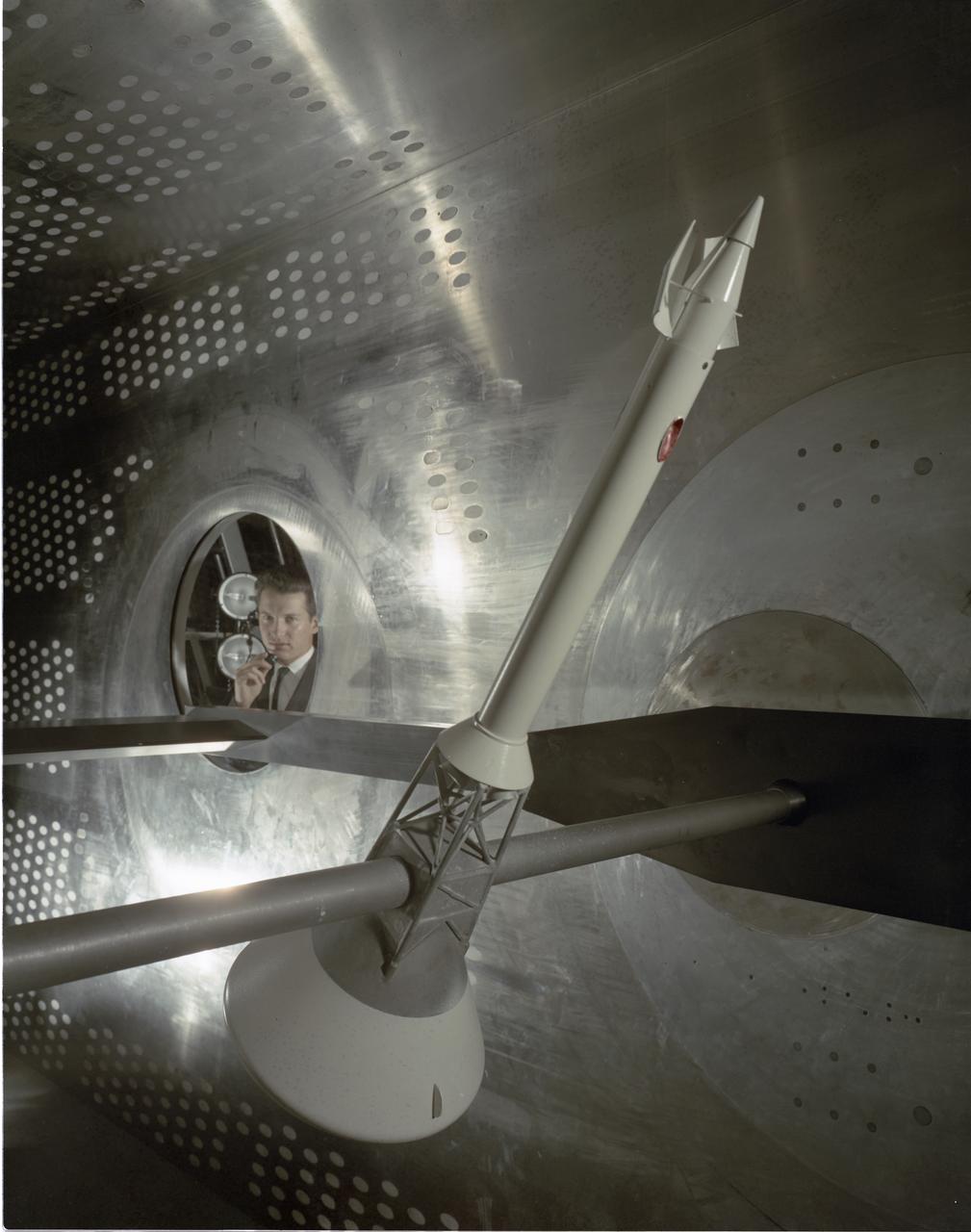
APOLLO STABILITY TEST IN THE 8X6 FOOT WIND TUNNEL - MODEL IS SHOWN WITH MODULE TOWER AND CANARDS
The Saturn I S-IV stage (second stage) for the SA-7 mission being prepared for shipment to Cape Canaveral, Florida. The S-IV stage had six RL-10 engines, which used liquid hydrogen and liquid oxygen as its propellants, arranged in a circle. Each RL-10 engine produced a thrust of 15,000 pounds for a total combined thrust of 90,000 pounds. The SA-7 mission was launched on September 18, 1964 from Cape Canaveral, Florida, and its S-IV stage made the second orbital flight.
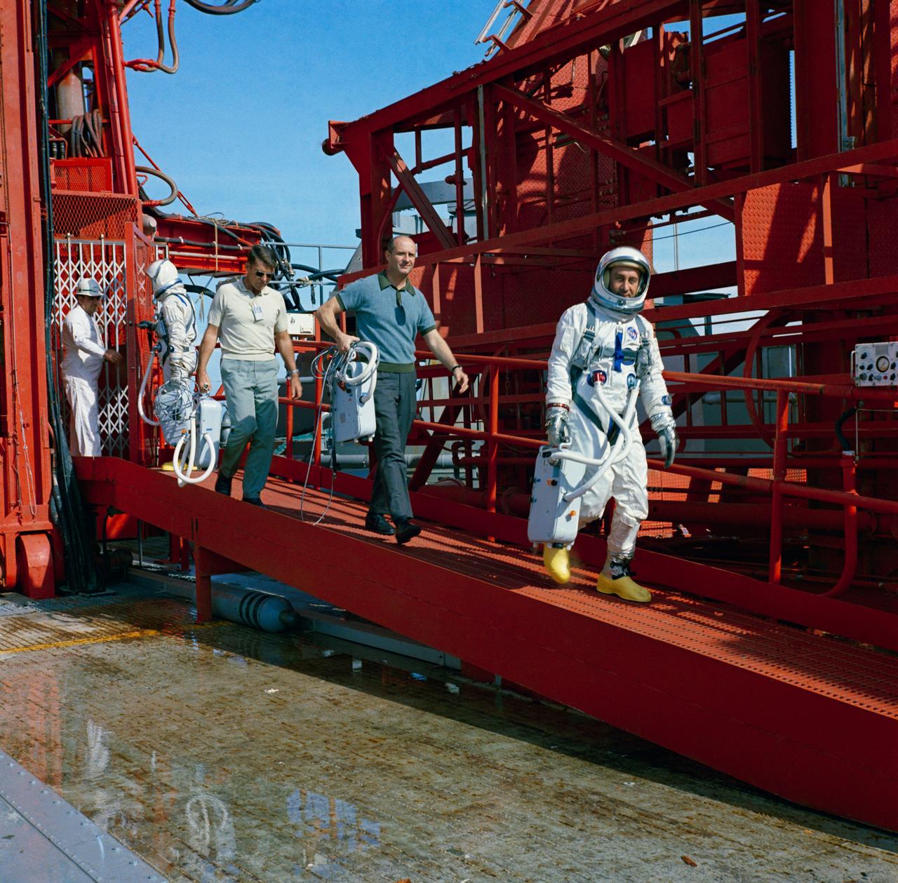
S64-40298 (24 Nov. 1964) --- Astronauts John W. Young, Walter M. Schirra Jr., Thomas P. Stafford and Virgil I. Grissom (left to right) are shown during egress training during Gemini-Titan 3 simulation launch at Pad 19.
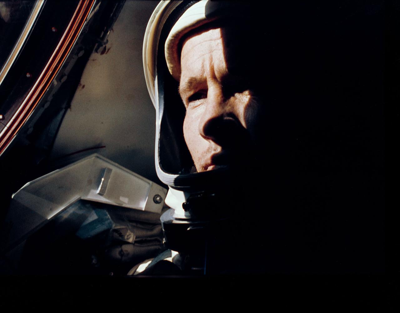
S65-30548 (3-7 June 1965) --- Astronaut Edward H. White II, Gemini IV pilot, is photographed onboard the Gemini-Titan 4 spacecraft during the four-day Earth-orbital mission. Photo credit: NASA
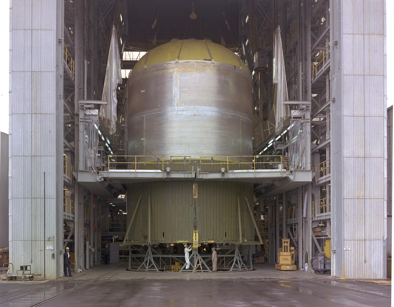
At the Marshall Space Flight Center (MSFC), the fuel tank assembly for the Saturn V S-IC-T (static test stage) fuel tank assembly is mated to the liquid oxygen (LOX) tank in building 4705. This stage underwent numerous static firings at the newly-built S-IC Static Test Stand at the MSFC west test area. The S-IC (first) stage used five F-1 engines that produced a total thrust of 7,500,000 pounds as each engine produced 1,500,000 pounds of thrust. The S-IC stage lifted the Saturn V vehicle and Apollo spacecraft from the launch pad.
S64-31447 (10 Sept. 1964) --- Astronaut Roger B. Chaffee Editor's Note: Astronaut Chaffee died in the Apollo/Saturn 204 fire accident at Cape Canaveral, Florida, on Jan. 27, 1967, along with astronauts Virgil I. Grissom and Edward H. White II.
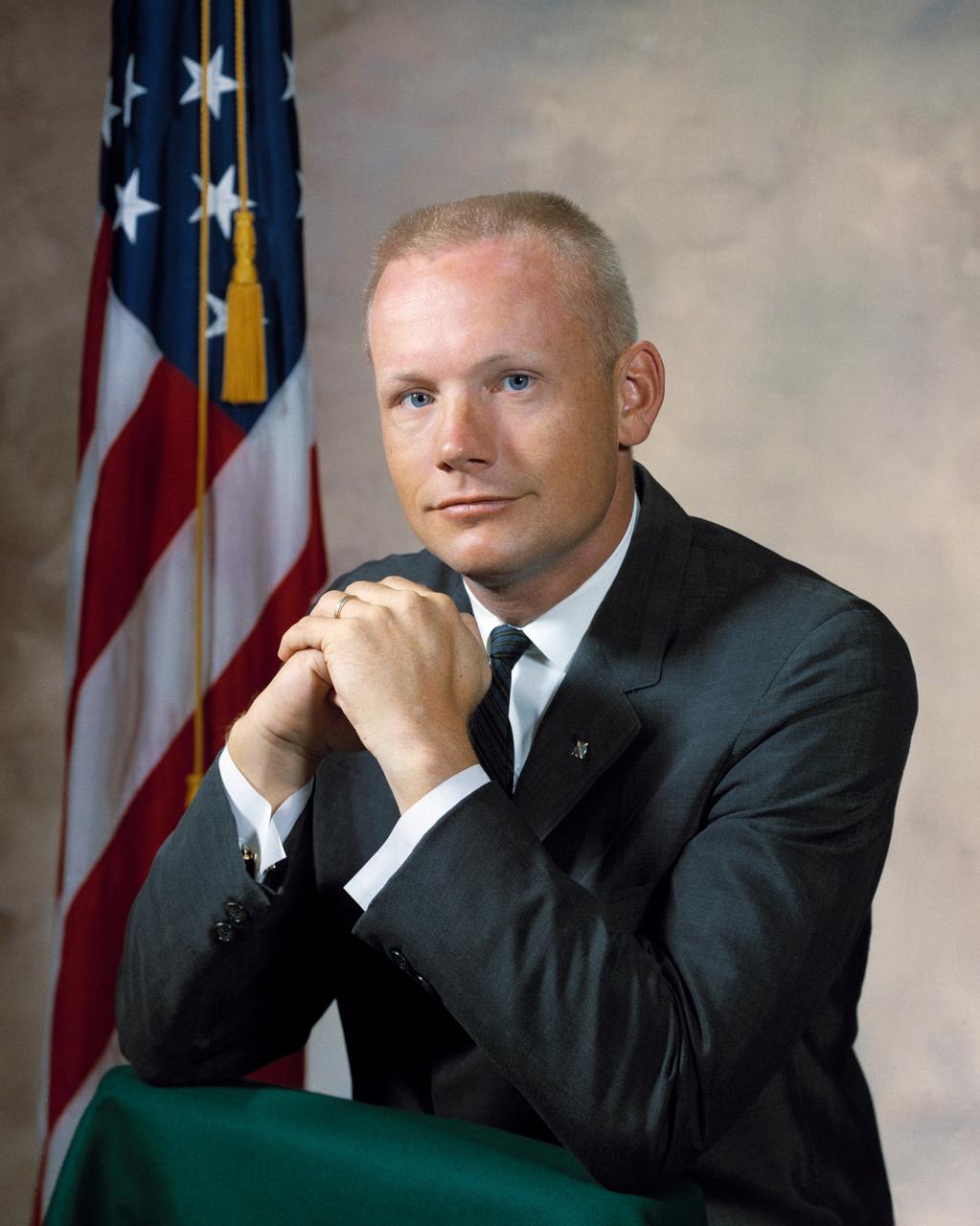
S64-31452 (1964) --- Astronaut Neil A. Armstrong. Photo credit: NASA
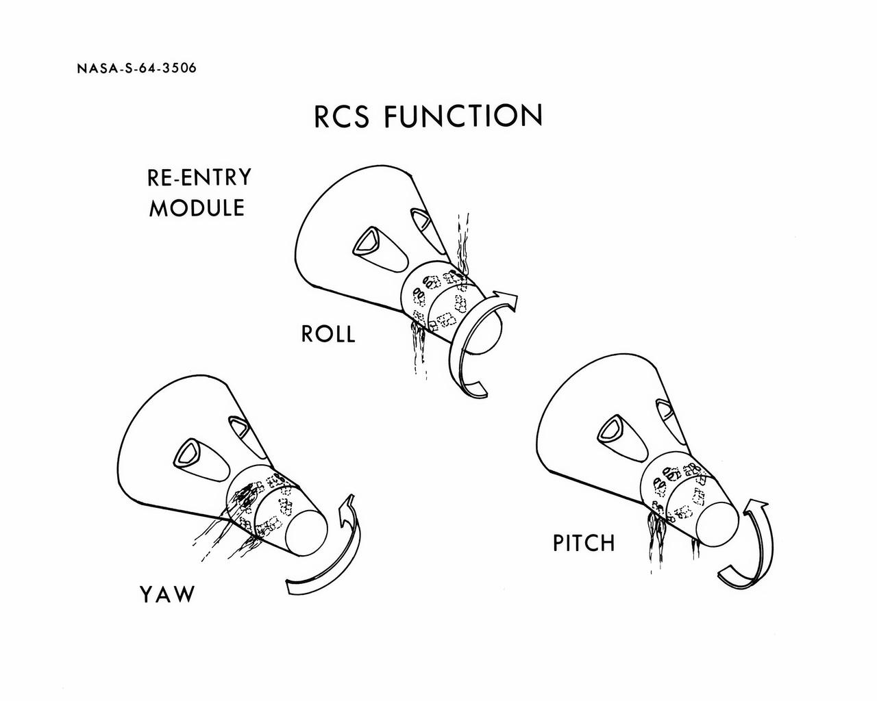
S64-03506 (1964) --- Diagrams shows Gemini spacecraft functions of the thrusters in the Gemini spacecraft's re-entry control system. Thrusters may be fired in various combinations to cause yaw, roll and pitch.
.059 SCALE MODEL OF APOLLO LAUNCH ESCAPE SYSTEM
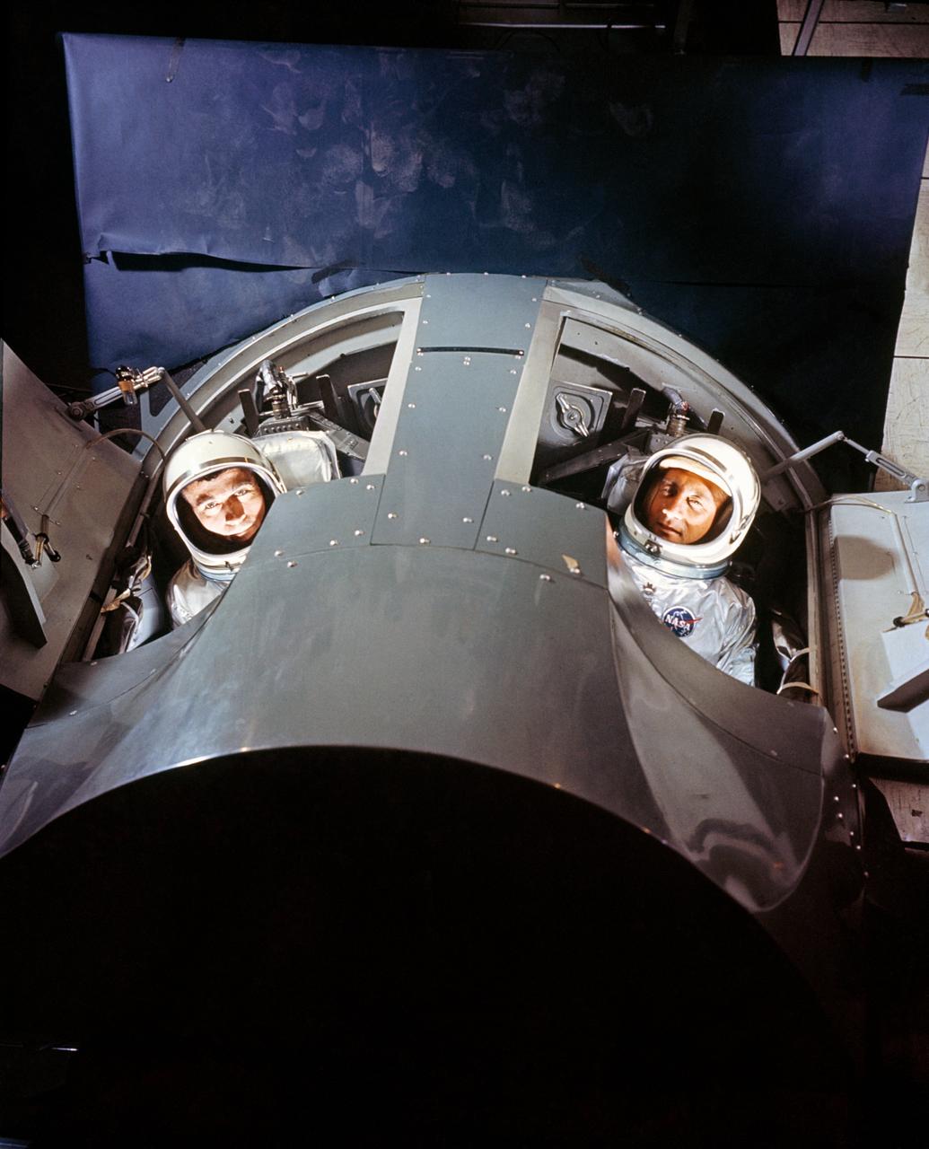
S64-25295 (March 1964) --- Astronauts Virgil I. (Gus) Grissom (right) and John W. Young, prime crew for the first manned Gemini mission (GT-3), are shown inside a Gemini mission simulator at McDonnell Aircraft Corp., St. Louis, MO. The simulator will provide Gemini astronauts and ground crews with realistic mission simulation during intensive training prior to actual launch.
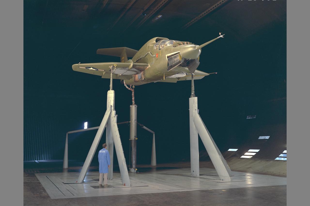
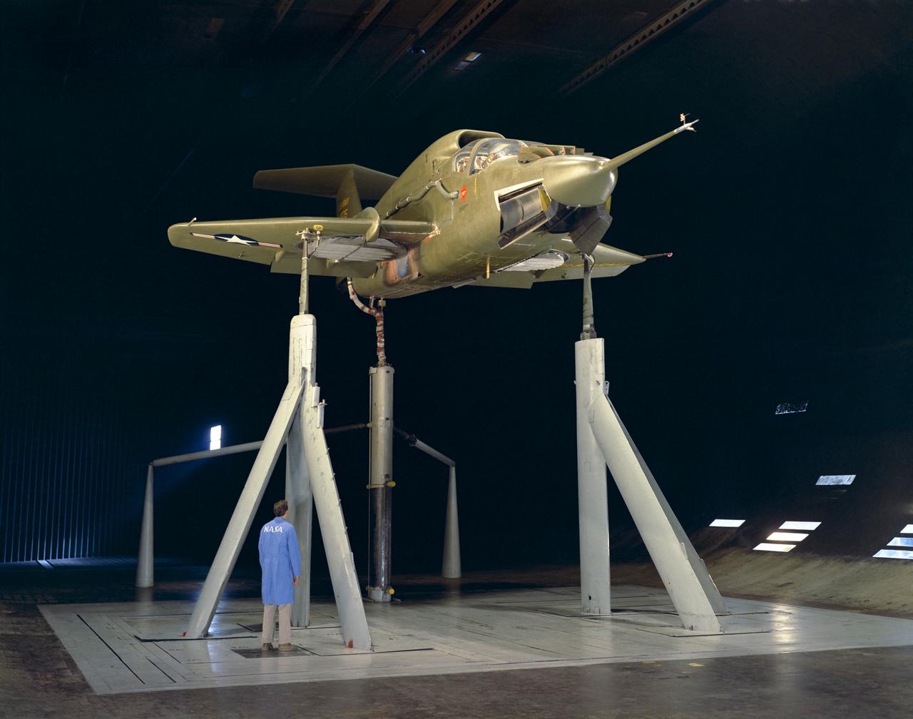
XV-5A airplane installed in 40x80ft Subsonic Wind Tunnel at NASA Ames Research Center with Tom Mills. The propulsive lift system was tested to determine power-on performance characteristics in preparation for flight tests. Used in Memoiors of an Aeronautical Engineer, Flight Tests at Ames Research Center 1940-1970 NASA-SP-2002-4526 (Seth B. Anderson)
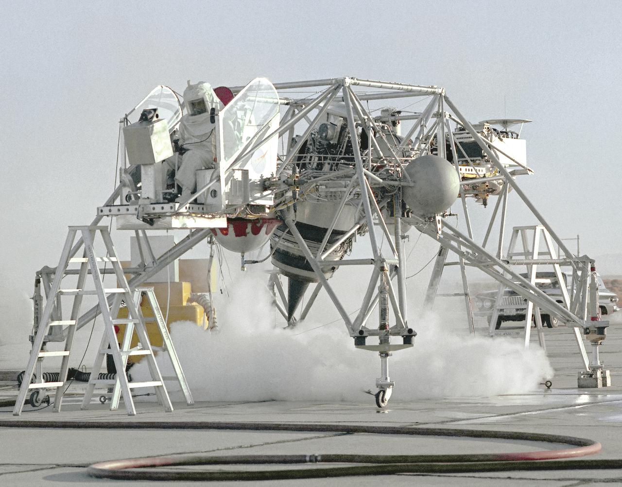
This 1964 NASA Flight Reserch Center photograph shows a ground engine test underway on the Lunar Landing Research Vehicle (LLRV) number 1. When Apollo planning was underway in 1960, NASA was looking for a simulator to profile the descent to the Moon's surface. Three concepts surfaced: an electronic simulator, a tethered device, and the ambitious Dryden contribution, a free-flying vehicle. All three became serious projects, but eventually the NASA Flight Research Center's (FRC) Landing Research Vehicle (LLRV) became the most significant one. Hubert M. Drake is credited with originating the idea, while Donald Bellman and Gene Matranga were senior engineers on the project, with Bellman, the project manager. Simultaneously, and independently, Bell Aerosystems Company, Buffalo, N.Y., a company with experience in vertical takeoff and landing (VTOL) aircraft, had conceived a similar free-flying simulator and proposed their concept to NASA headquarters. NASA Headquarters put FRC and Bell together to collaborate. The challenge was; to allow a pilot to make a vertical landing on Earth in a simulated Moon environment, one sixth of the Earth's gravity and with totally transparent aerodynamic forces in a "free flight" vehicle with no tether forces acting on it. Built of tubular aluminum like a giant four-legged bedstead, the vehicle was to simulate a lunar landing profile from around 1500 feet to the Moon's surface. To do this, the LLRV had a General Electric CF-700-2V turbofan engine mounted vertically in gimbals, with 4200 pounds of thrust. The engine, using JP-4 fuel, got the vehicle up to the test altitude and was then throttled back to support five-sixths of the vehicle's weight, simulating the reduced gravity of the Moon. Two hydrogen-peroxide lift rockets with thrust that could be varied from 100 to 500 pounds handled the LLRV's rate of descent and horizontal translations. Sixteen smaller hydrogen-peroxide rockets, mounted in pairs, gave the pilot control in pitch, yaw,
S64-31711 (1964) --- Astronaut Clinton C. Williams.
The fuel tank assembly for the Saturn V S-IC (first) stage arrived at the Marshall Space Flight Center, building 4707, for mating to the liquid oxygen tank. The fuel tank carried kerosene as its fuel. The S-IC stage used five F-1 engines, that used kerosene and liquid oxygen as propellant and each engine provided 1,500,000 pounds of thrust. This stage lifted the entire vehicle and Apollo spacecraft from the launch pad.
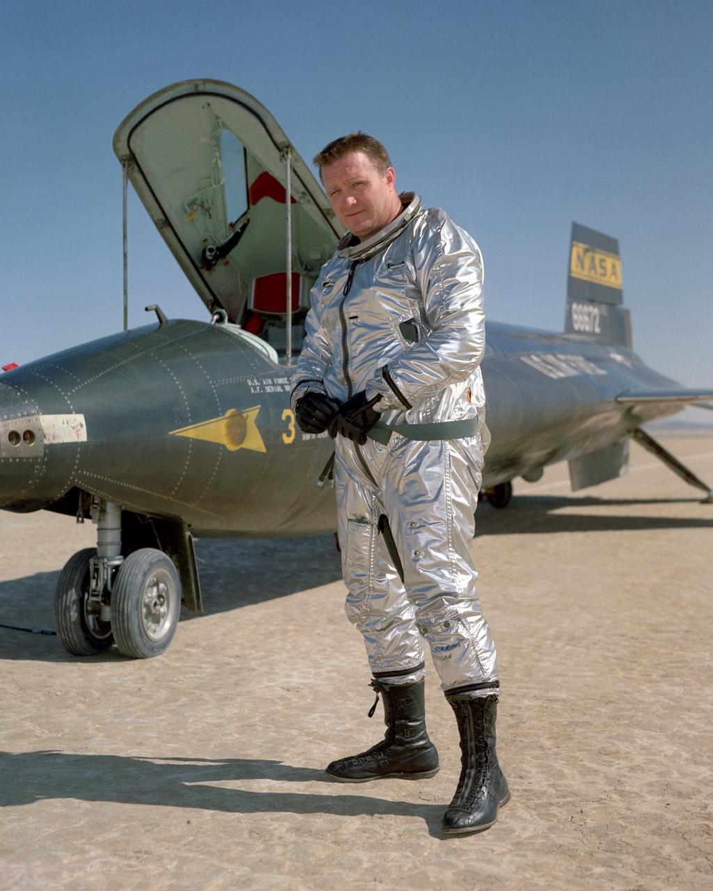
John B. McKay was one of the first pilots assigned to the X-15 flight research program at NASA's Flight Research Center, Edwards, Calif. As a civilian research pilot and aeronautical engineer, he made 30 flights in X-15s from October 28, 1960, until September 8, 1966. His peak altitude was 295,600 feet, and his highest speed was 3863 mph (Mach 5.64). McKay was with the NACA and NASA from February 8,1951 until October 5, 1971 and specialized in high-speed flight research programs. He began as an NACA intern, but assumed pilot status on July 11, 1952. In addition to the X-l5, he flew such experimental aircraft as the D-558-1, D-558-2, X-lB, and the X-lE. He has also served as a research pilot on flight programs involving the F-100, F-102, F-104, and the F-107. Born on December 8, 1922, in Portsmouth, Va., McKay graduated from Virginia Polytechnic Institute in 195O with a Bachelor of Science degree in Aeronautical Engineering. During World War II he served as a Navy pilot in the Pacific Theater, earning the Air Medal and Two Clusters, and a Presidential Unit Citation. McKay wrote several technical papers, and was a member of the American Institute of Aeronautics and Astronautics, as well as the Society of Experimental Test Pilots. He passed away on April 27, 1975.
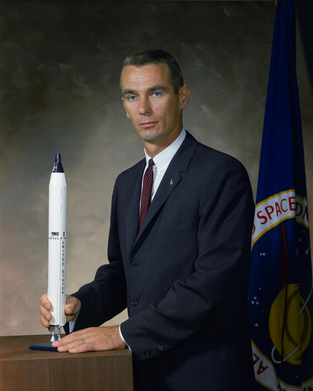
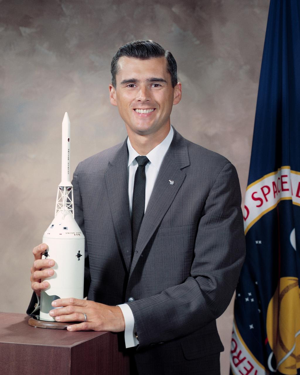
S64-31845 (10 Sept. 1964) --- Portrait of astronaut Eugene A. Cernan in civilian clothes with model of Gemini spacecraft and launch vehicle on table in front of him. Photo credit: NASA
KENNEDY SPACE CENTER, FLA. -- NASA Administrator James T. Webb holds the microphone as President Lyndon B. Johnson (center) and astronaut Walter Schirra (right) converse during the President's visit to the Kennedy Space Center.
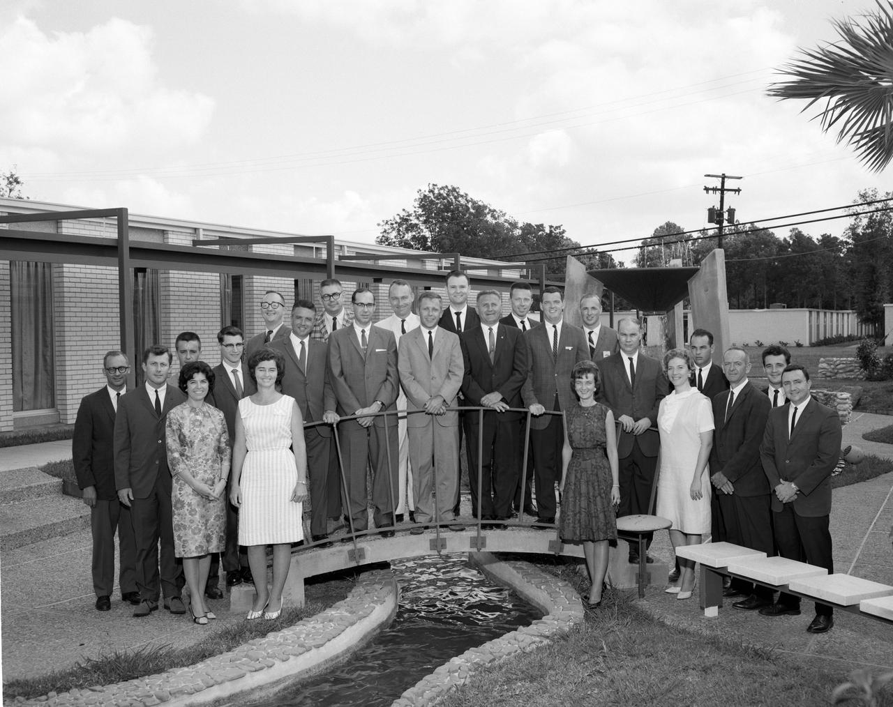
Group shot of the nucleus of the 1960 Flight Operations Division for the Mercury Program. Image taken at the Houston Petroleum Center (HPC) in Houston, TX, prior to their move to the Manned Spacecraft Center (MSC). This photo was published in the Space News Roundup, 07/08/1964. The women are (L-R): Doris Folkes, Cathy Osgood, Shirley Hunt and Mary Shep Burton. The men are (L-R): Dick Koos, Paul Brumberg, John O'Loughlin, Emil Schiesser, Jim Dalby, Morris Jenkins, Carl Huss, John Mayer, Bill Tindall, Hal Beck, Charlie Allen, Ted Skopinski, Jack Hartung, Glynn Lunney, John Shoosmith, Bill Reini, Lyn Dunseith, Jerry Engel, Harold Miller and Clay Hicks. ( 26644 ); Houston, TX
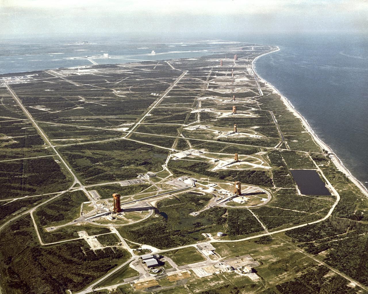
CAPE CANAVERAL, Fla. -- Overall aerial view of "Missile Row," Cape Kennedy Air Force Station. The view is looking north, with the Vehicle Assembly Building under construction in the upper left-hand corner. Photo credit: NASA
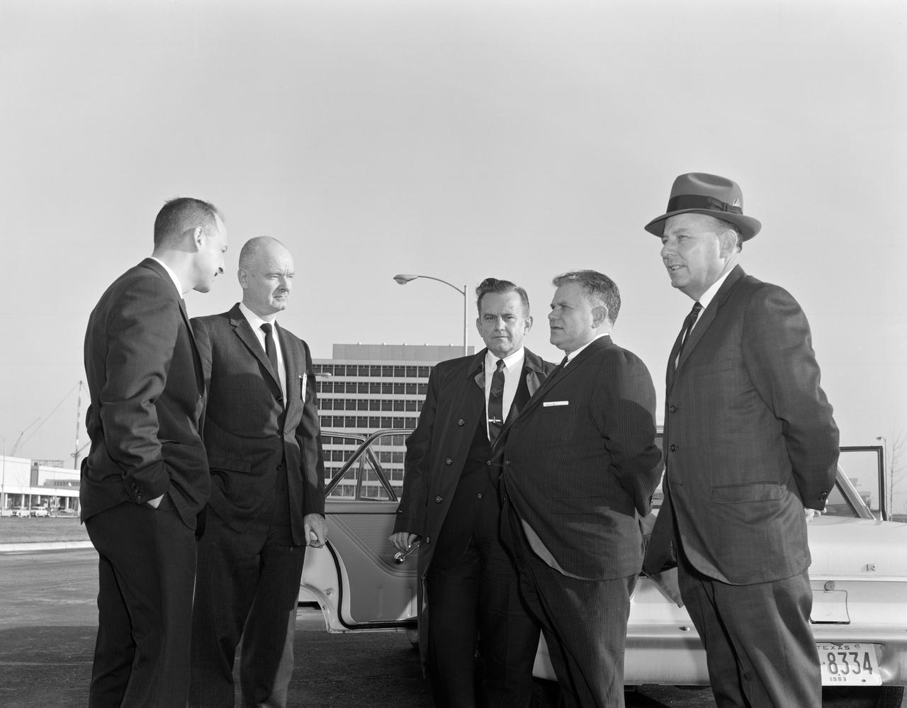
George Low, Joseph Piland, Philip Hamburger, Congressman Olin Teague from Texas; and, Congressman Joe D. Waggoner from Louisiana at the entrance to Site 1, Clear Lake, prior to briefing for the House Subcommittee on Manned Spaceflight. MSC, Houston, TX
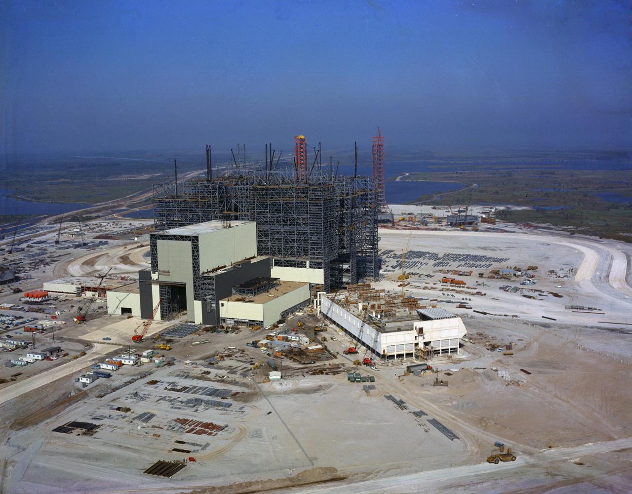
KENNEDY SPACE CENTER, FLA. -- Aerial view of VAB (Vehicle Assembly Buiding) construction.
S64-31476 (1964) --- Astronaut Theodore C. Freeman.
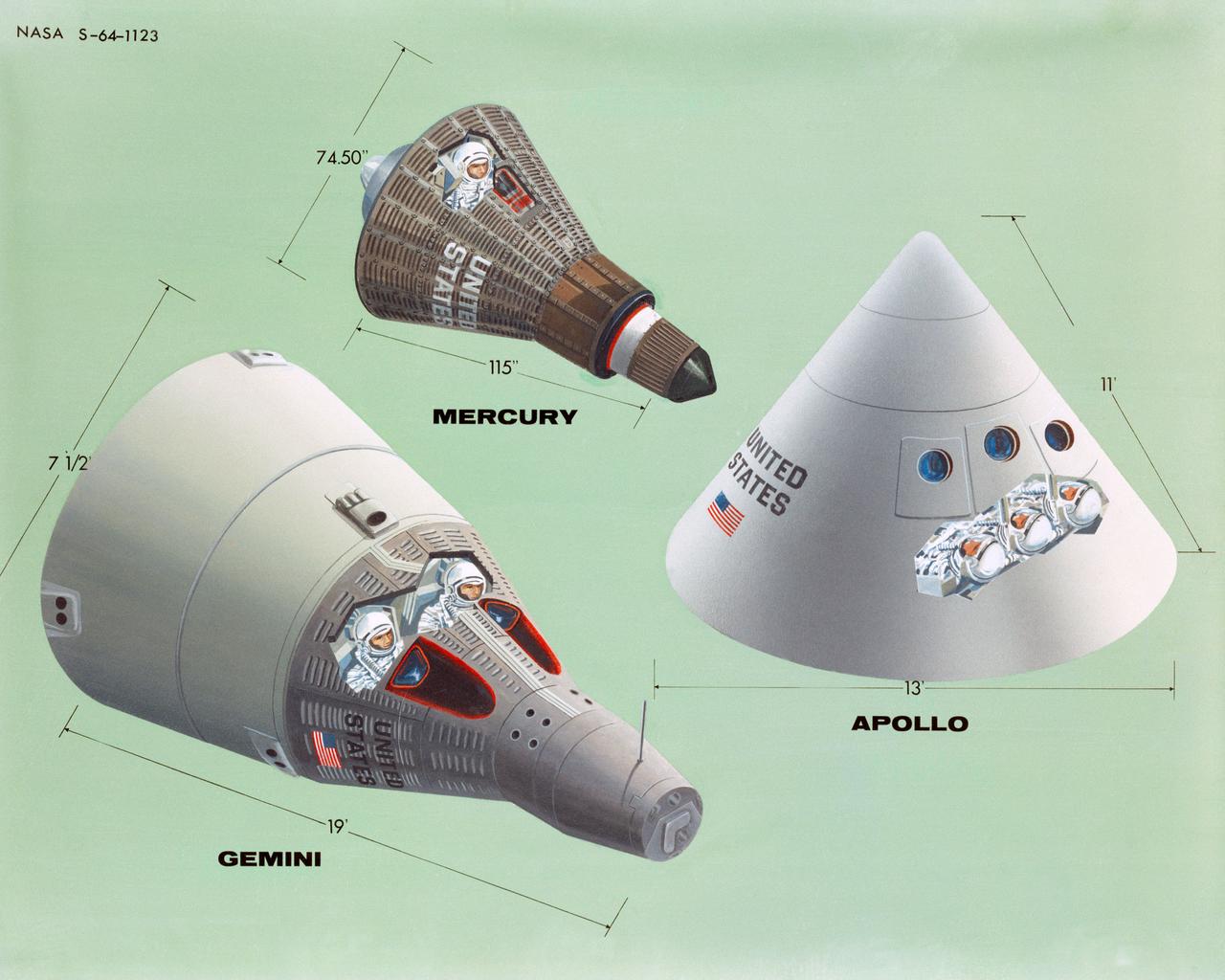
S64-01123 (1964) --- Artist concept illustrating the relative sizes of the one-man Mercury spacecraft, the two-man Gemini spacecraft, and the three-man Apollo spacecraft. Photo credit: NASA
David Reese and Alvin Seiff interpret the results from tests designed to study spacecraft configuration and performance in a particular atmosphere
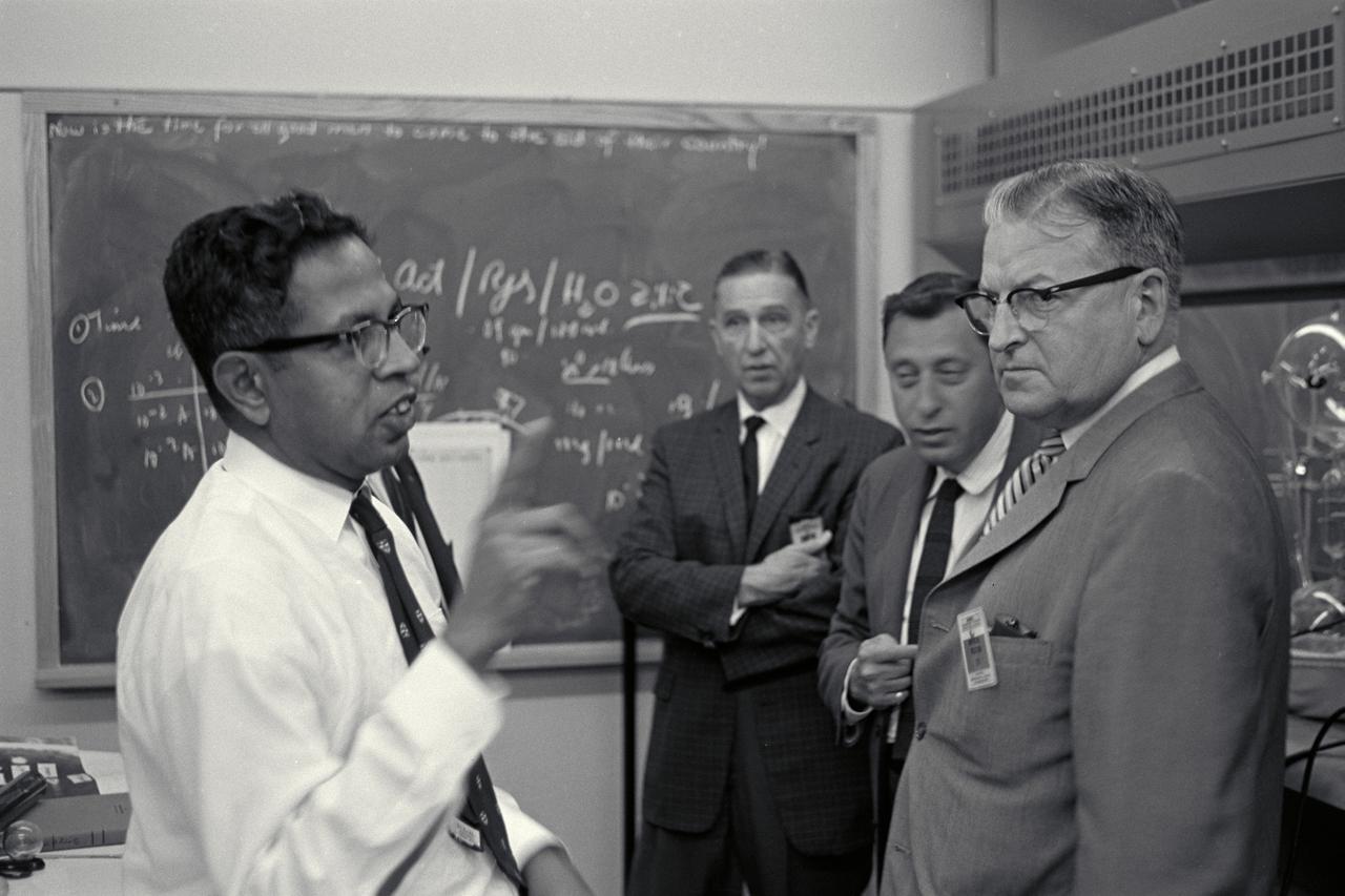
Dr Cyril Ponnamperuma and Dr Harold Klein discuss work with Congressman William K Van Pelt during visit and tour of Ames
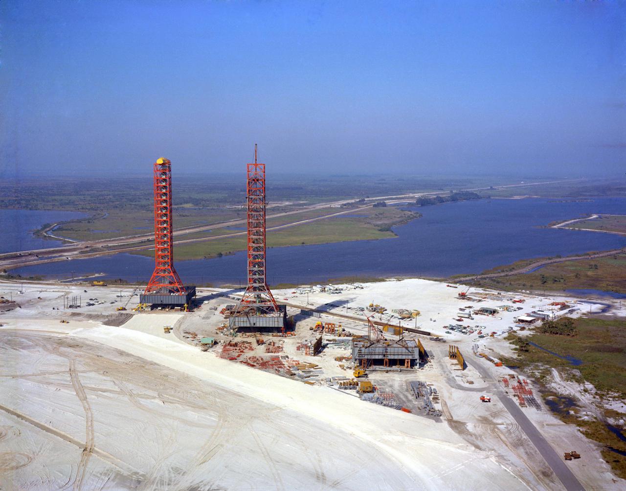
KENNEDY SPACE CENTER, FLA. -- Aerial view of Launcher Umbilical Towers, Merritt Island Launch Area (MILA).
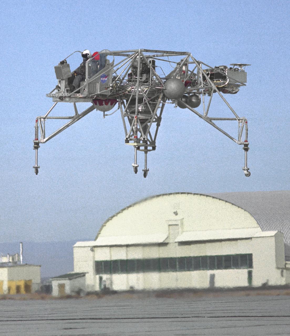
An inflight view from the left side of the Lunar Landing Research Vehicle, is shown in this 1964 NASA Flight Research Center photograph. The photograph was taken in front of the old NACA hangar located at the South Base, Edwards Air Force Base. When Apollo planning was underway in 1960, NASA was looking for a simulator to profile the descent to the Moon's surface. Three concepts surfaced: an electronic simulator, a tethered device, and the ambitious Dryden contribution, a free-flying vehicle. All three became serious projects, but eventually the NASA Flight Research Center's (FRC) Landing Research Vehicle (LLRV) became the most significant one. Hubert M. Drake is credited with originating the idea, while Donald Bellman and Gene Matranga were senior engineers on the project, with Bellman, the project manager. Simultaneously, and independently, Bell Aerosystems Company, Buffalo, N.Y., a company with experience in vertical takeoff and landing (VTOL) aircraft, had conceived a similar free-flying simulator and proposed their concept to NASA headquarters. NASA Headquarters put FRC and Bell together to collaborate. The challenge was; to allow a pilot to make a vertical landing on earth in a simulated Moon environment, one sixth of the earth's gravity and with totally transparent aerodynamic forces in a "free flight" vehicle with no tether forces acting on it. Built of tubular aluminum like a giant four-legged bedstead, the vehicle was to simulate a lunar landing profile from around 1500 feet to the Moon's surface. To do this, the LLRV had a General Electric CF-700-2V turbofan engine mounted vertically in gimbals, with 4200 pounds of thrust. The engine, using JP-4 fuel, got the vehicle up to the test altitude and was then throttled back to support five-sixths of the vehicle's weight, simulating the reduced gravity of the Moon. Two hydrogen-peroxide lift rockets with thrust that could be varied from 100 to 500 pounds handled the LLRV's rate of descent and horizontal transla