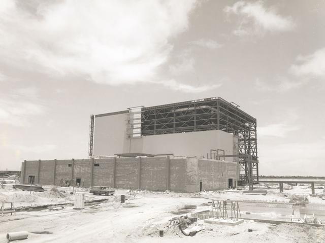
View of OPF High Bay No. 1 and Low Bay construction, 1976
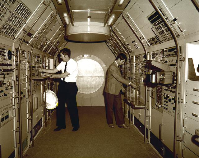
Astronauts Joseph Kerwin (left) and William Lenoir familiarize themselves with equipment aboard the Spacelab mockup during a 1976 visit to the Marshall Space Flight Center. Kerwin and Lenoir were part of an astronaut group briefed on Spacelab subsystems and crew activities by Marshall scientists and engineers. The Marshall Space Flight Center had management responsibility for Spacelab.
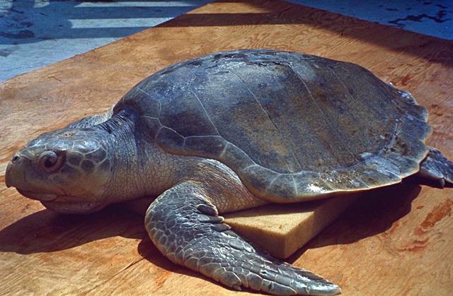
KENNEDY SPACE CENTER, FLA. -- Hundreds of turtles like this one lay their eggs on the beaches near Kennedy Space Center.
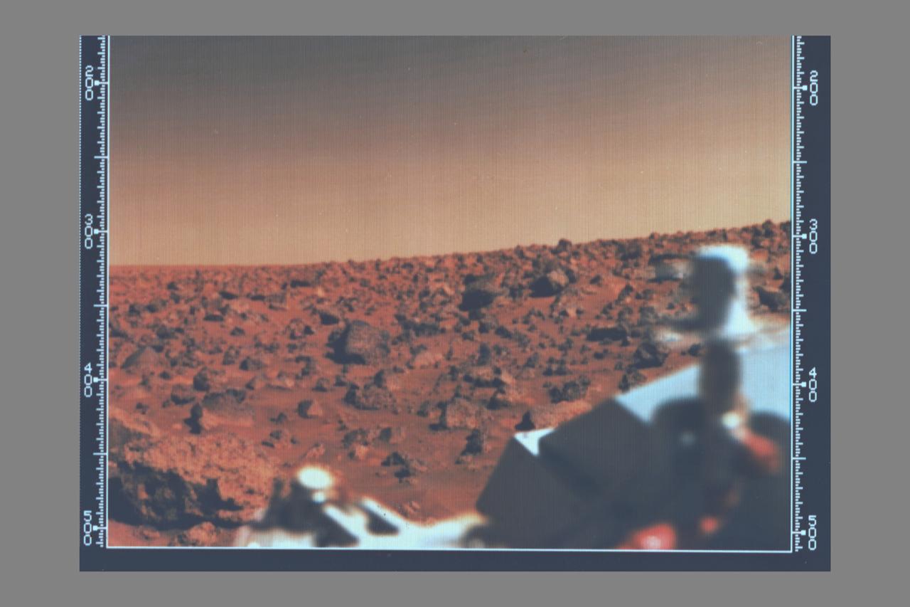
Viking 2 A utopian bright summer afternoon on Mars -- Looking south from Viking 2 on September 7, 1976 the orange-red surface of the nearly level plain upon which the spacecraft sits is seen strewn with rocks as large as three feet across. Many of these rocks are porous and sponge-like, similar to some of Earth's volcanic rocks. Other rocks are coarse-grained such as the large rock at lower left. Between the rocks, the surface is blanketed with fine-grained materials that, in places, is piled into small drifts and banked against some of the larger blocks. The cylindrical mast with the orange cable is the low-gain antenna used to receive cammands form Earth. (JPL ref: P-17690 color)
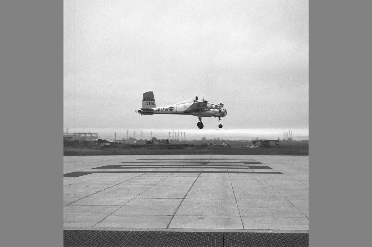
X-14 Aircraft during hover flight tests at VTOL test pad

Dr. Hans Mark attends Ames Federal Women's Week luncheon
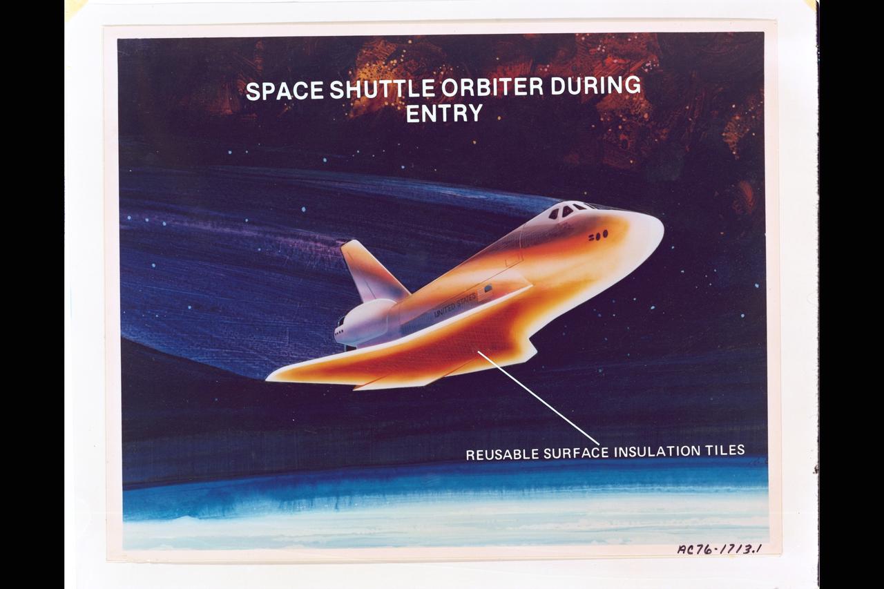
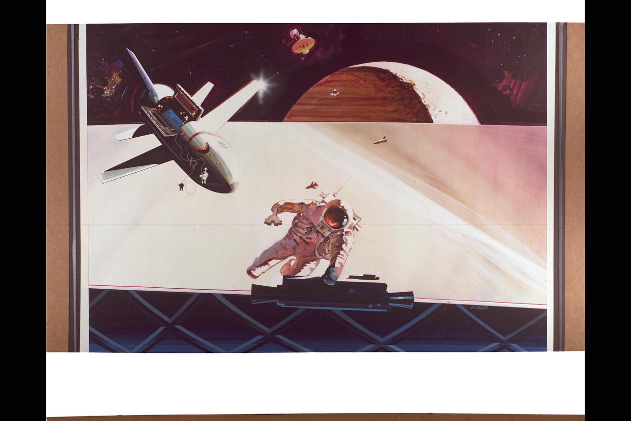
Artist: Rick Guidice NASA artwork of Space Shuttle Orbiter during re-entry showing Reusable Surface Insulation Tiles. (Text overlay)
Artwork by: Rick Guidice Space Colonization - Bernal Sphere. EXTERIOR VIEW LOOKING INTO SPHERE.
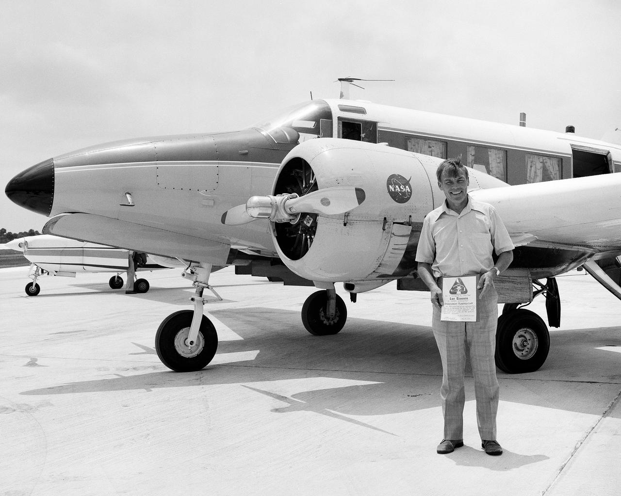
CAPE CANAVERAL, Fla. -- Kennedy Space Center Director Lee Scherer receives an Ambassador Plenipotentary certificate after successfully landing the NASA-6 aircraft on the runway at the Shuttle Landing Facility. This was the first touchdown of an aircraft on Kennedy's Shuttle Landing Facility. The certificate reads: 'Be it known that Lee Scherer is hereby appointed Ambassador Plenipotentary in recognition of his aeronautical skills in bringing the old to the new by having an antique aircraft and an antique pilot land on the world's newest runway. Photo Credit: NASA
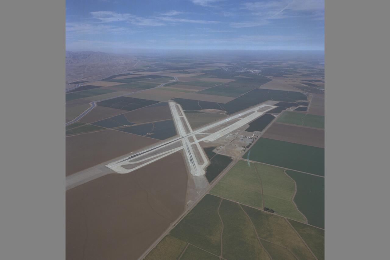
Crows Landing Naval Auxiliary Landing Field and flight research facility, Crows Landing, CA Note: Used in publication in Flight Research at Ames; 57 Years of Development and Validation of Aeronautical Technology NASA SP-1998-3300 fig. 109
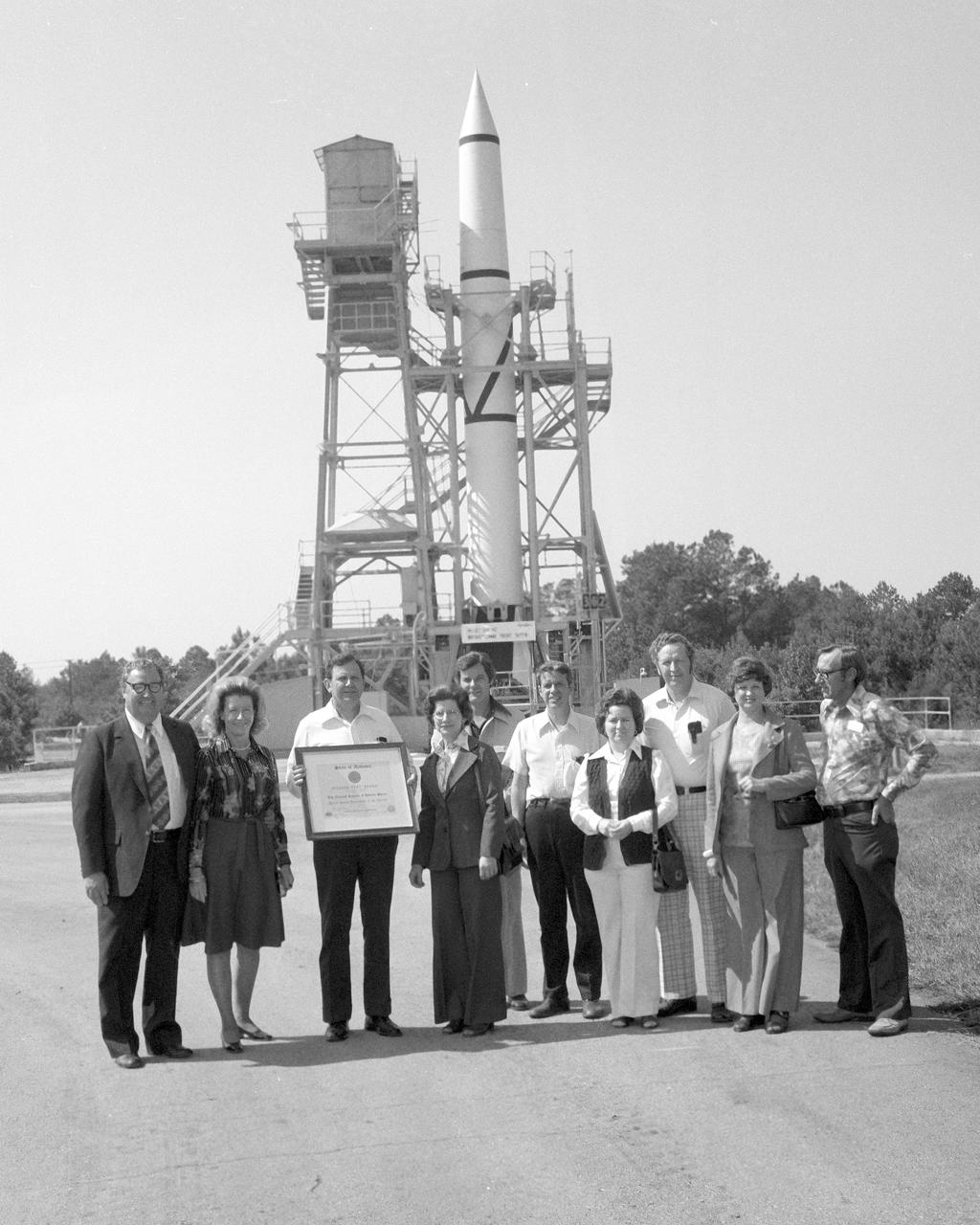
On October 02, 1976, Marshall Space Flight Center’s (MSFC) Redstone test stand was received into the National Registry of Historical Places. Photographed in front of the Redstone test stand along with their wives are (left to right), Madison County Commission Chairman James Record, Dr. William R. Lucas, MSFC Center Director from June 15, 1974 until July 3, 1986, (holding certificate), Ed, Buckbee, Space and Rocket Center Director; Harvie Jones, Huntsville Architect; Dick Smith; and Joe Jones.
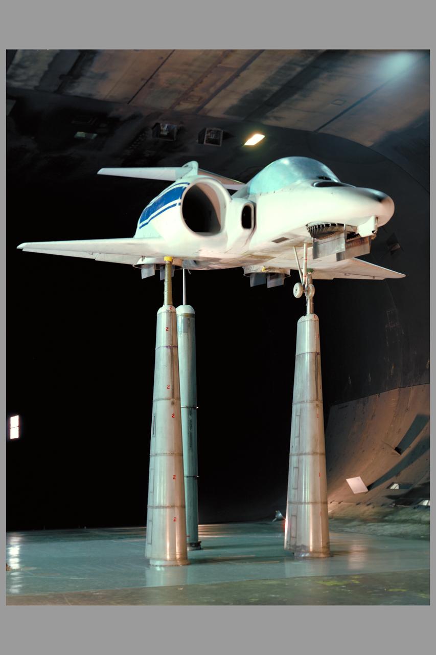
Multi Mission Lift Cruise Fan Model in 40x80ft W.T. Test (Test-490)
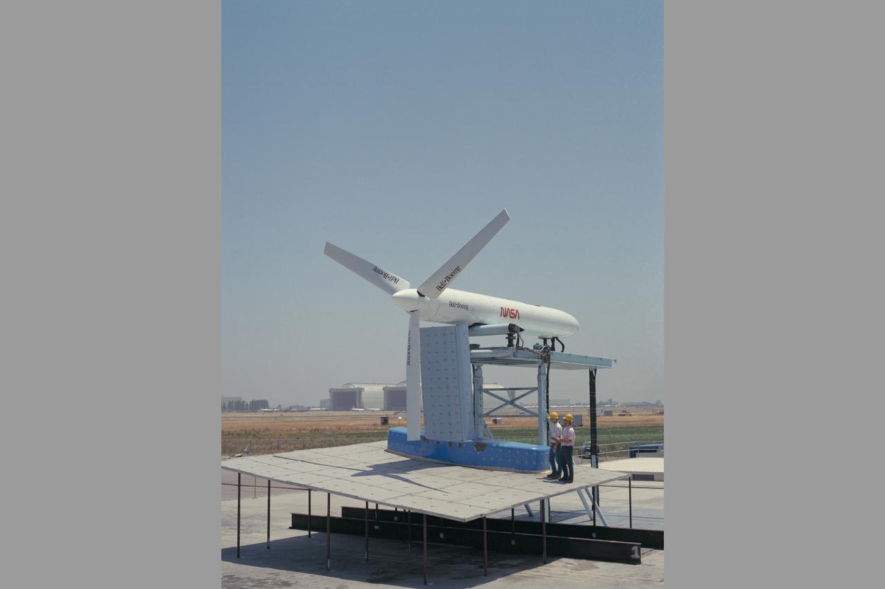
JVX/ATB Rotor Blade Project: Bell Boeing Rotor for the XV-15 tilt rotor Research Aircraft (TRRA)
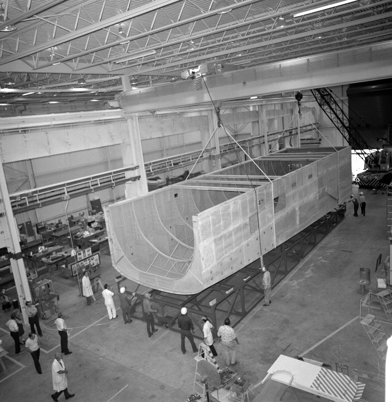
Eleven (11) wide-angle views and medium shots showing progess on construction of Shuttle Orbiter Mid-Body Mockup in Bldg. 9. Workers seen in views. JSC, Houston, TX
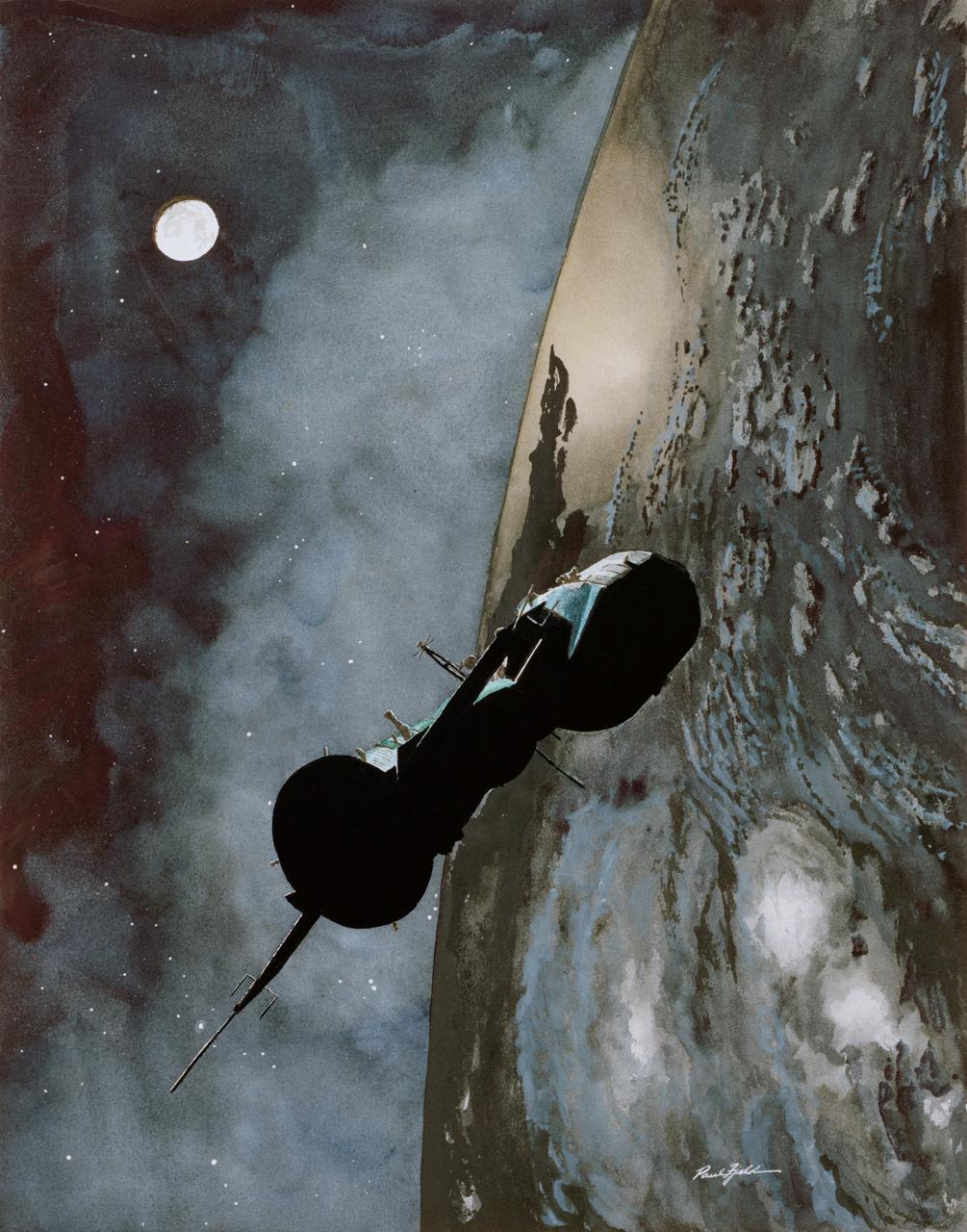
S76-22455 (1976) --- Apollo-Soyuz Test Project artist?s concept by Paul Fjeld.
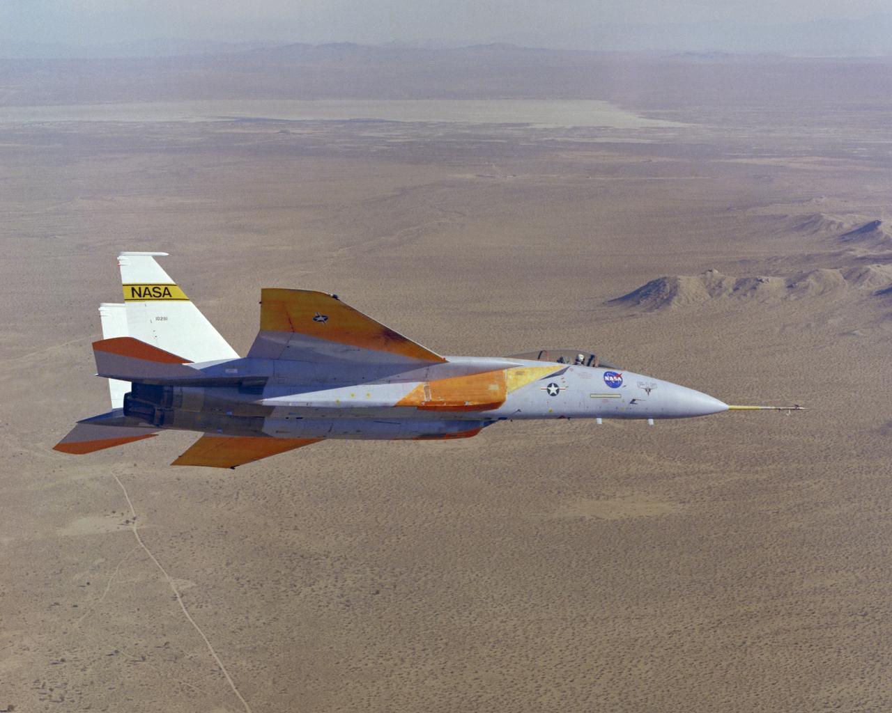
The number two F-15A (Serial #71-0281) was obtained by NASA from the U.S. Air Force in 1976 and was used for more than 25 advanced research projects involving aerodynamics, performance, propulsion control, control integration, instrumentation development, human factors, and flight test techniques. Included in these projects was its role as a testbed to evaluate aerodynamic pressures on Space Shuttle thermal protection tiles at specific altitudes and speeds.
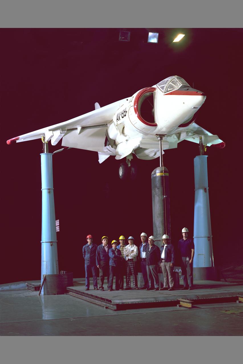
NASA/NAVAIR Marine AV-8B aircraft test-493 in 40x80ft. w.t. with test crew
Artist: Rick Guidice Building a Space Colony

F-18 HICL II model in 12ft w.t.
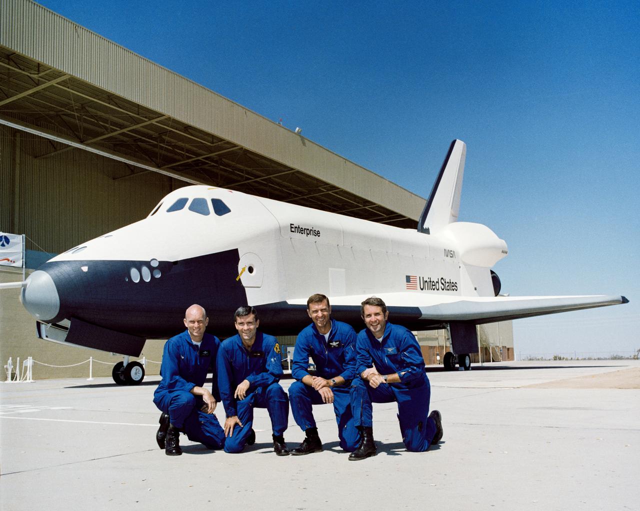
S76-29562 --- The two crews for the Space Shuttle Approach and Landing Tests (ALT) are photographed at the Rockwell International Space Division's Orbiter assembly facility at Palmdale, California on the day of the rollout of the Shuttle Orbiter 101 "Enterprise" spacecraft. They are, left to right, Astronauts C. Gordon Fullerton, pilot of the first crew; Fred W. Haise Jr., commander of the first crew; Joe H. Engle, commander of the second crew; and Richard H. Truly, pilot of the second crew. The DC-9 size airplane-like Orbiter 101 is in the background.
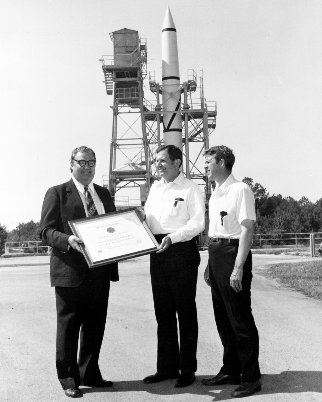
On October 02, 1976, Marshall Space Flight Center’s (MSFC) Redstone test stand was received into the National Registry of Historical Places. Photographed in front of the Redstone test stand are Dr. William R. Lucas, MSFC Center Director from June 15, 1974 until July 3, 1986, as he is accepting a certificate of registration from Madison County Commission Chairman James Record, and Huntsville architect Harvie Jones.

View of OPF High Bay No. 1 and Low Bay construction, 1976
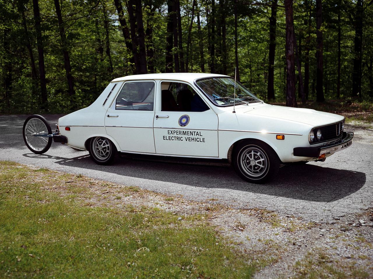
The National Aeronautics and Space Administration (NASA) Lewis Research Center tested 16 commercially-manufactured electric vehicles, including this Metro, during the mid-1970s. Lewis and the Energy Research and Development Administration (ERDA) engaged in several energy-related programs in the mid-1970s, including the Electric Vehicle Project. NASA and ERDA undertook the program in 1976 to determine the state of the current electric vehicle technology. As part of the project, Lewis and ERDA tested every commercially available electric car model. Electric Vehicle Associates, located in a Cleveland suburb, modified a Renault 12 vehicle to create this Metro. Its 1040-pound golfcart-type battery provided approximately 106 minutes of operation. The tests analyzed the vehicle’s range, acceleration, coast-down, braking, and energy consumption. Some of the vehicles had analog data recording systems to measure the battery during operation and sensors to determine speed and distance. The researchers found the performance of the different vehicles varied significantly. In general, the range, acceleration, and speed were lower than that found on conventional vehicles. They also found that traditional gasoline-powered vehicles were as efficient as the electric vehicles. The researchers concluded, however, that advances in battery technology and electric drive systems would significantly improve efficiency and performance.
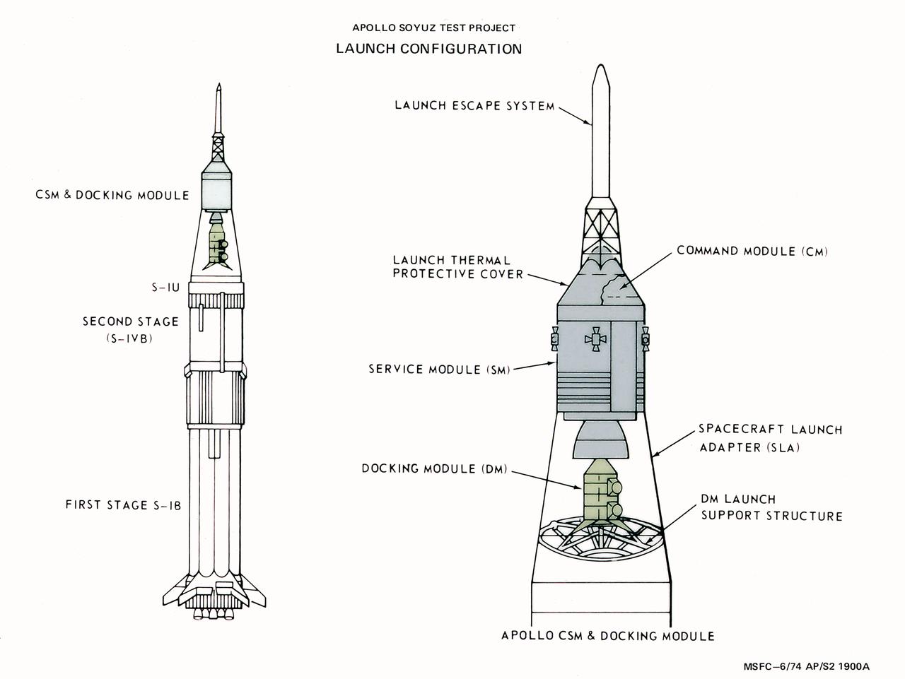
This illustration depicts the launch configuration of the Apollo spacecraft for the Apollo-Soyuz Test Project (ASTP). The ASTP was the first international docking of the U.S.'s Apollo spacecraft and the U.S.S.R.'s Soyuz spacecraft in space. A joint engineering team from the two countries met to develop a docking system that permitted the two spacecraft to link in space and allowed the two crews to travel from one spacecraft to the other. This system entailed developing a large habitable Docking Module (DM) to be carried on the Apollo spacecraft to facilitate the joining of two dissimilar spacecraft. The Marshall Space Flight Center was responsible for development and sustaining engineering of the Saturn IB launch vehicle during the mission.
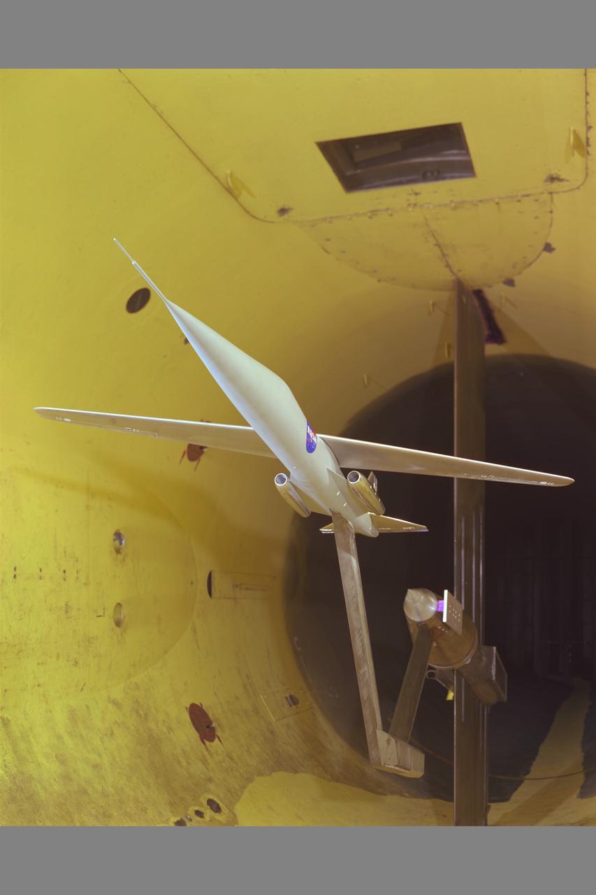
SPACE SHUTTLE VEHICLE (SSV) 0.36 SCALE MODEL, 40X80FT W.T. TESTING - TAIL FLAPS
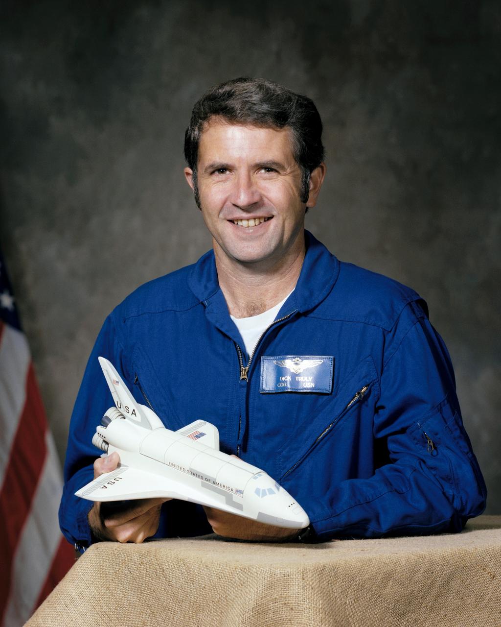
S76-28364 (1976) --- Astronaut Richard H. Truly
NASA/NAVAIR Marine AV-8B aircraft test-493 in 40x80ft. w.t.
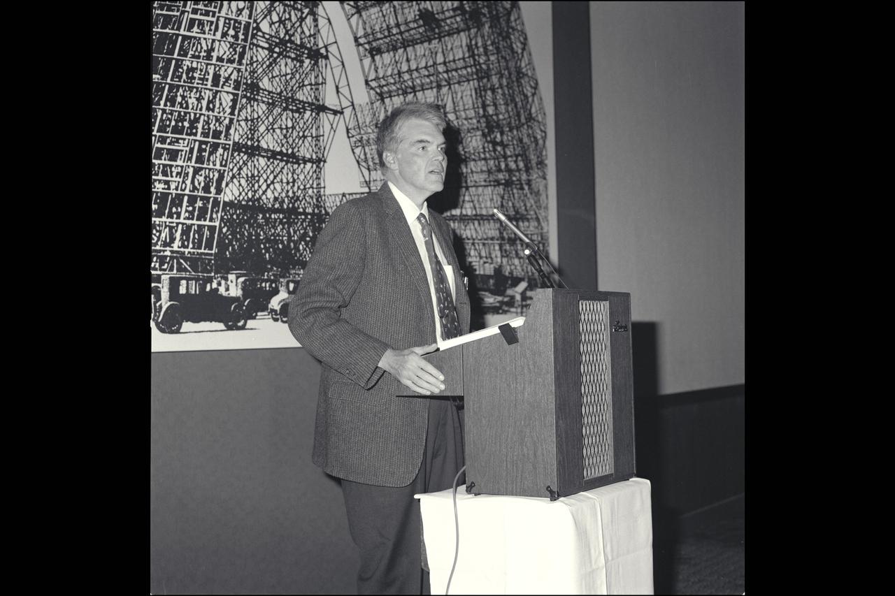
Dr. Hans Mark speaks at the Federa Women's Week Luncheon held at the NAS Moffett Field Offiers Club
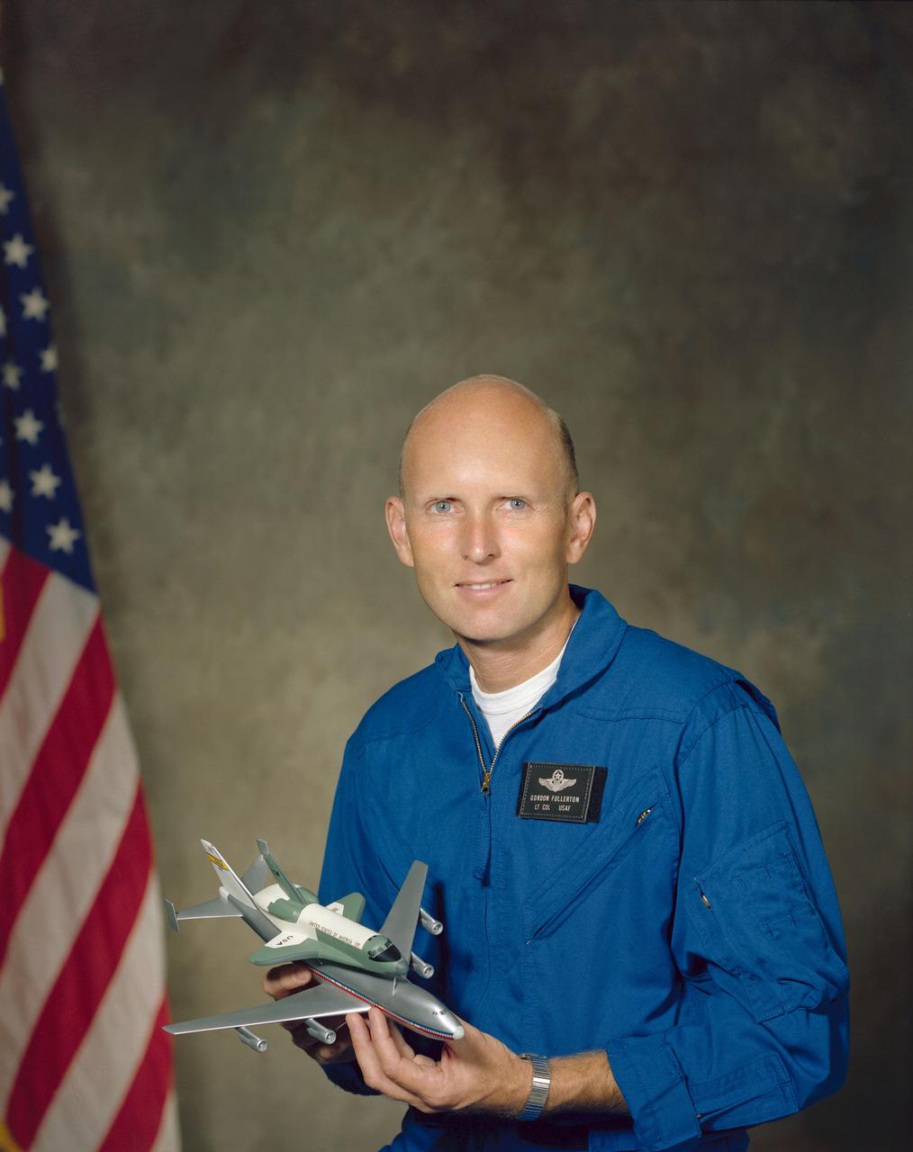
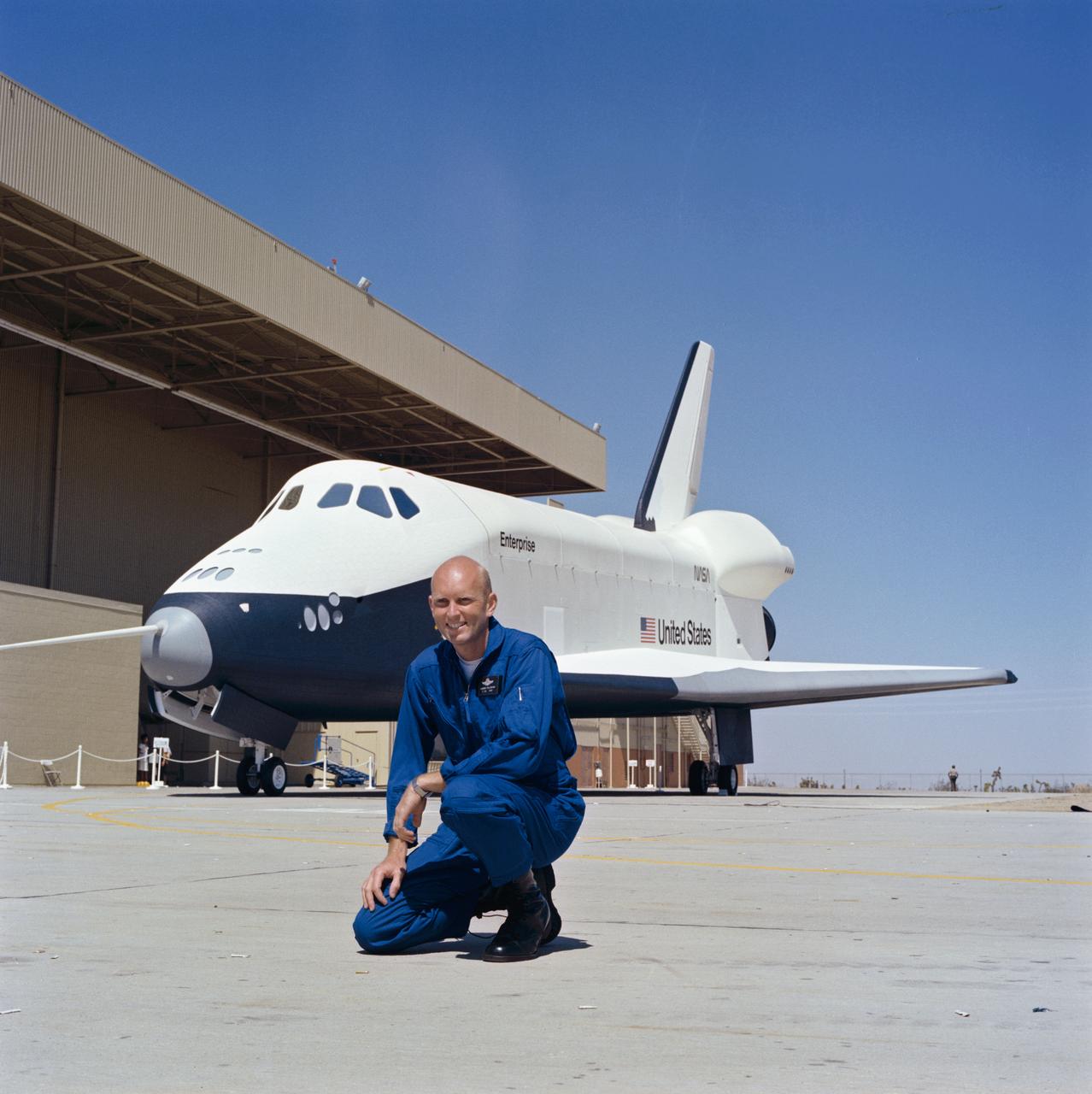
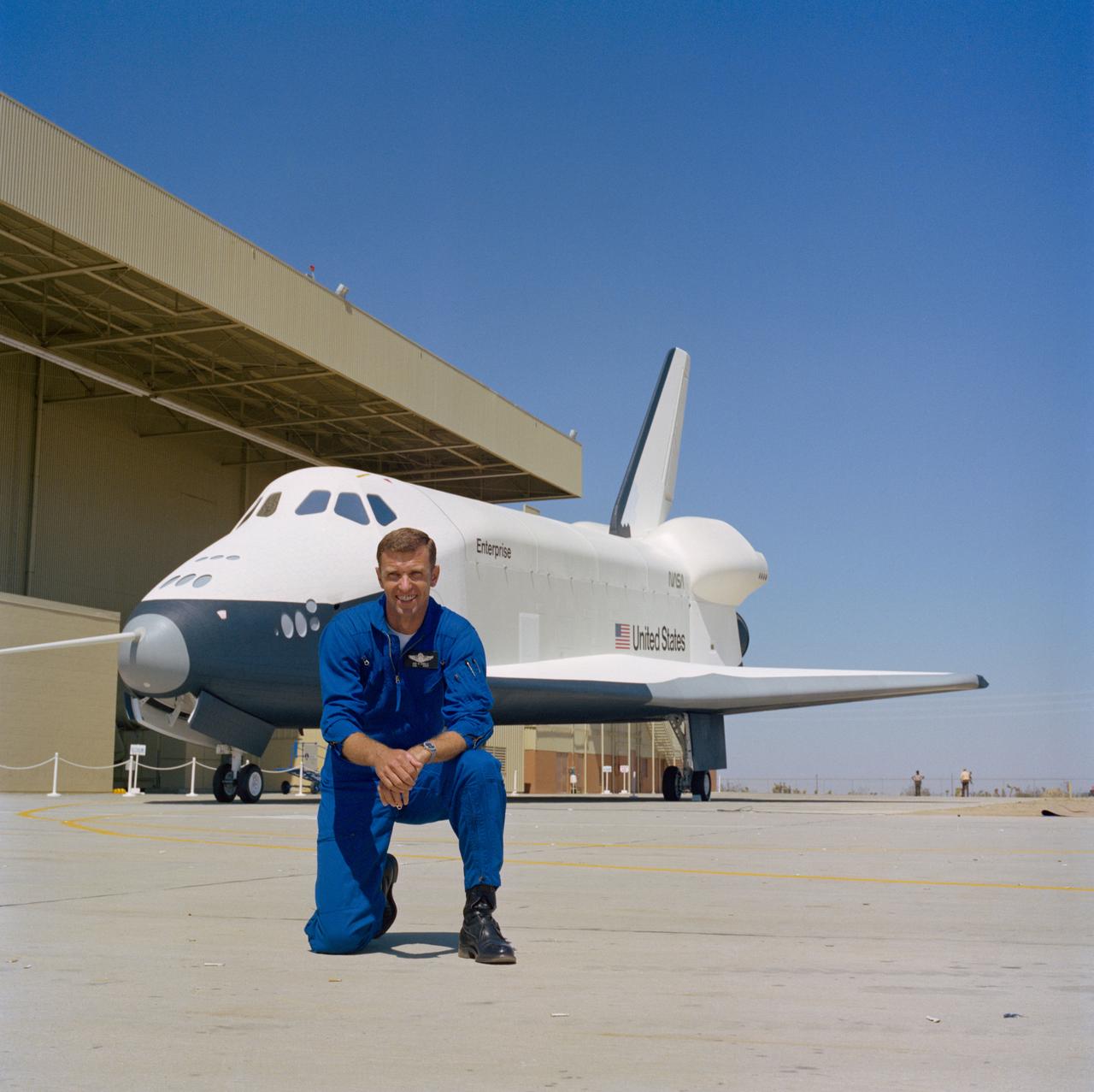
S76-28476 (8 Sept 1976) --- Astronaut C. Gordon Fullerton in flight suit holding a model of the space shuttle.
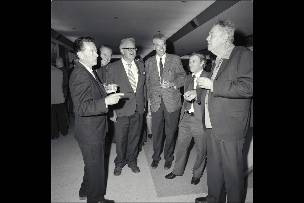
The Ames spirit of free and vigorous discussion; Left to right: R. T. Jones, Jack Nielsen, Hans Mark, Leonard Roberts and Harvey Allen during an award ceremony honoring R.T. Jones.
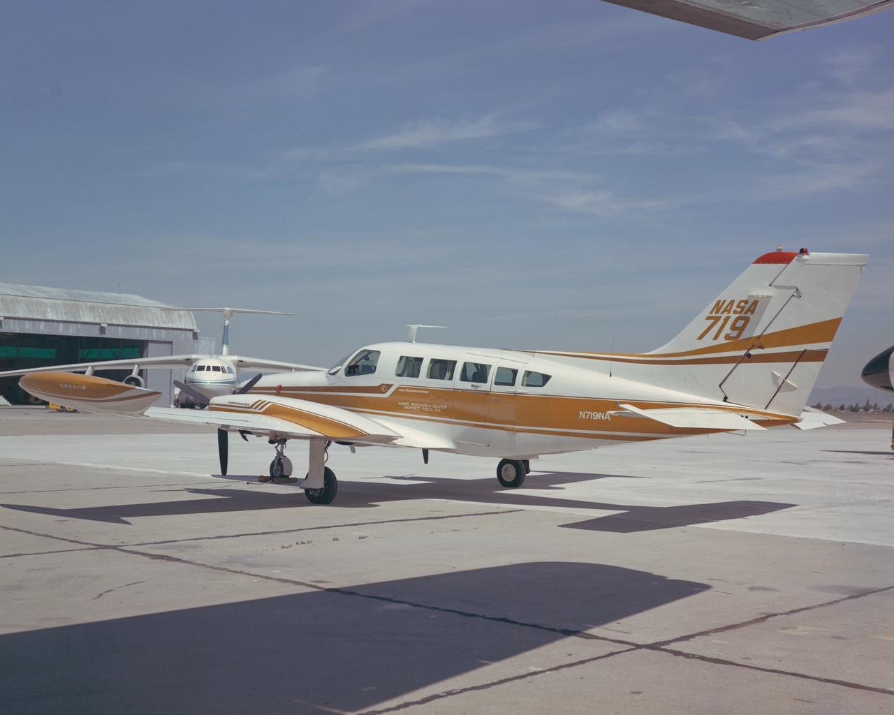
Cessna 402B (NASA-719) on the Ramp. An integrated digital flight management, guidance and navigation system was developed by an industry team from Honeywell and King Radio under the direction of George Callas and Dallas Denery and demonstrated on a Cessna 402B for general aviation applications. Note: Used in publication in Flight Research at Ames; 57 Years of Development and Validation of Aeronautical Technology NASA SP-1998-3300 fig. 86 - ref. 90
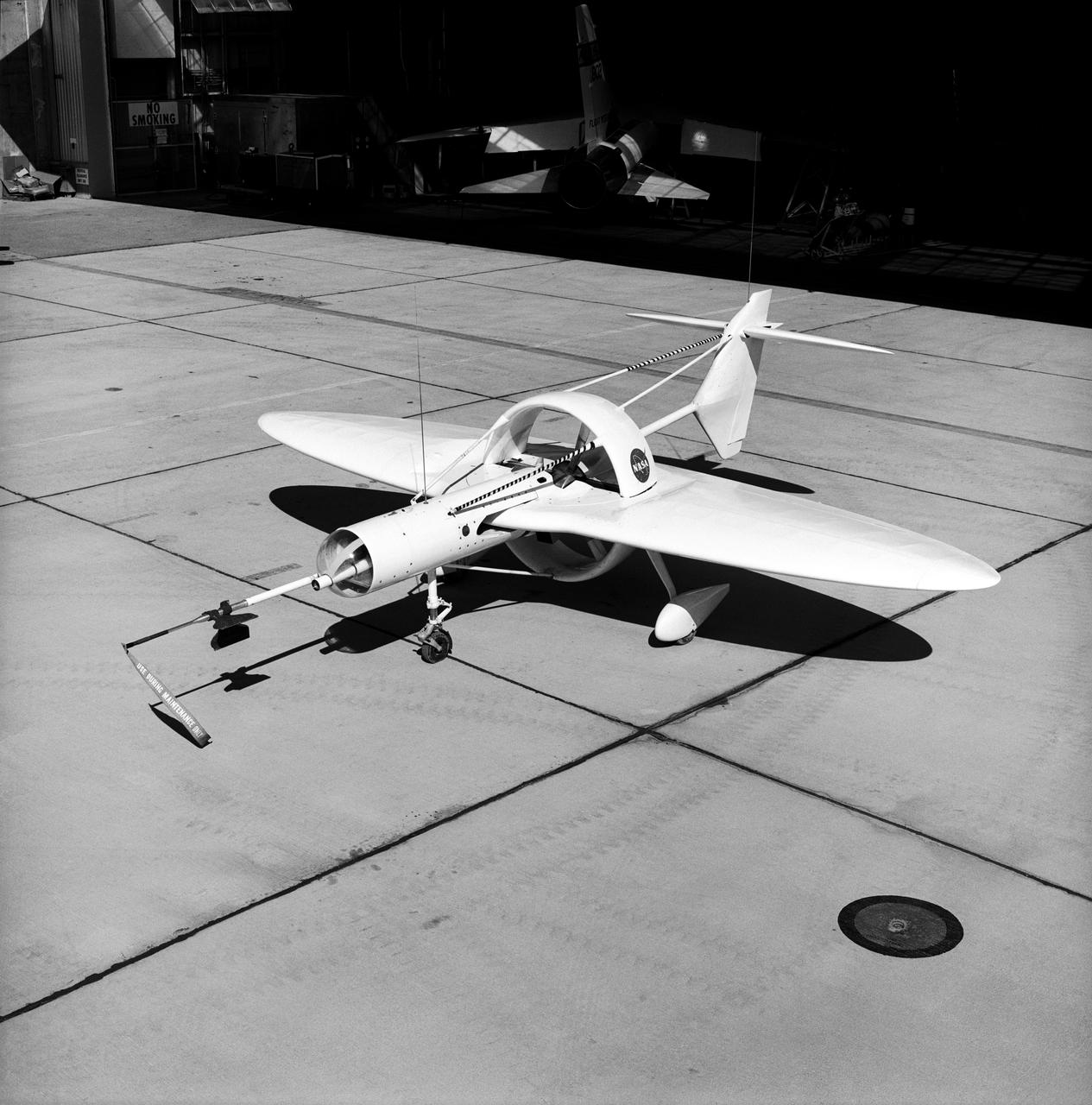
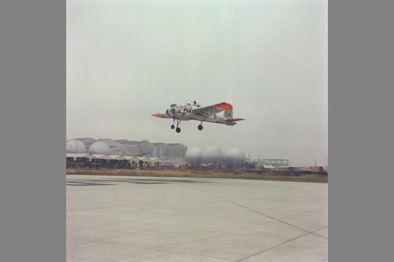
This 1976 photograph of the Oblique Wing Research Aircraft was taken in front of the NASA Flight Research Center hangar, located at Edwards Air Force Base, California. In the photograph the noseboom, pitot-static probe, and angles-of-attack and sideslip flow vanes(covered-up) are attached to the front of the vehicle. The clear nose dome for the television camera, and the shrouded propellor for the 90 horsepower engine are clearly seen.
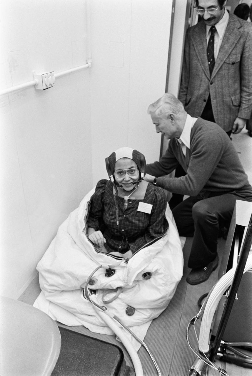
Spacelab simulations crew members during medical testing. Photo is of Patricia Cowings being zipped into the one-meter-diameter rescue ball during physical tests. Assisting her is Joe Schmitt, a suit technician.
S76-29559 (17 Sept 1976) --- Astronaut C. Gordon Fullerton, pilot of the first crew for the Space Shuttle Approach and Landing Tests (ALT), is photographed at the Rockwell International Space Division's Orbiter assembly facility at Palmdale, California on the day of the rollout of the Shuttle Orbiter 101 "Enterprise" spacecraft. The DC-9 size airplane-like Orbiter 101 is in the background.
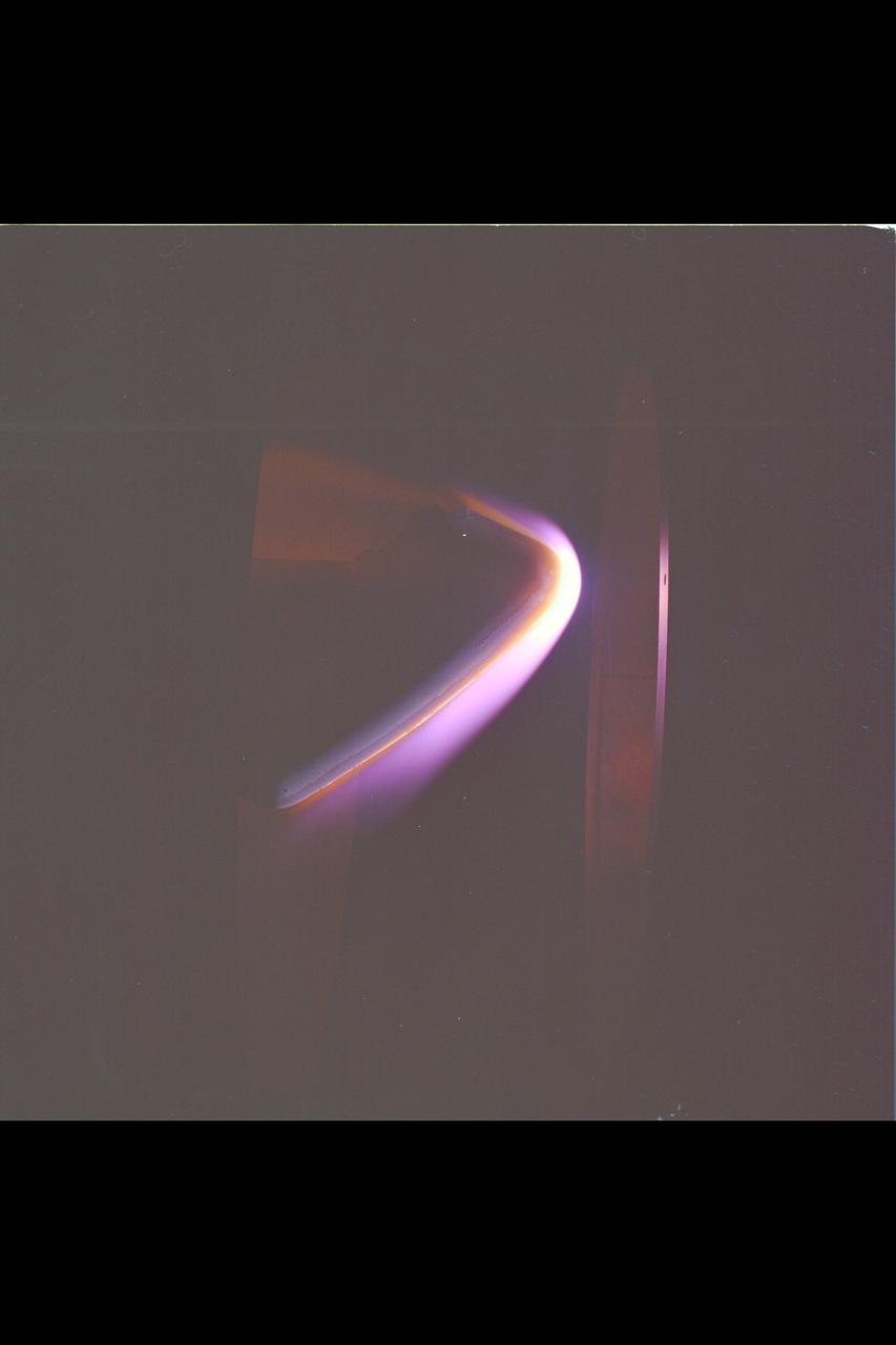
Space Shuttle tile test in 60MW Interaction Heating Facility N-238 (used in NASA/AMES publication 'Searching the Horizon' - A History of Ames Research Center SP-4304)
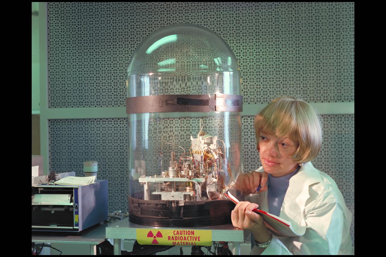
Bonnie Dalton with the Viking test module lab
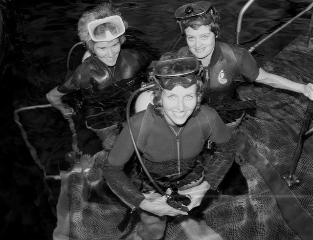
Candid shots of Carolyn Griner (front), Drs. Mary-Helen Johnston and Ann Whitaker (L to R) wearing scuba gear at the Neutral Buoyancy Simulator (NBS) for training.

This is a cutaway illustration of the Space Shuttle external tank (ET) with callouts. The giant cylinder, higher than a 15-story building, with a length of 154-feet (47-meters) and a diameter of 27.5-feet (8.4-meters), is the largest single piece of the Space Shuttle. During launch, the ET also acts as a backbone for the orbiter and solid rocket boosters. Separate pressurized tank sections within the external tank hold the liquid hydrogen fuel and liquid oxygen oxidizer for the Shuttle's three main engines. During launch, the ET feeds the fuel under pressure through 17-inch (43.2-centimeter) ducts that branch off into smaller lines that feed directly into the main engines. The main engines consume 64,000 gallons (242,260 liters) of fuel each minute. Machined from aluminum alloys, the Space Shuttle's external tank is currently the only part of the launch vehicle that is not reused. After its 526,000-gallons (1,991,071 liters) of propellants are consumed during the first 8.5-minutes of flight, it is jettisoned from the orbiter and breaks up in the upper atmosphere, its pieces falling into remote ocean waters. The Marshall Space Flight Center was responsible for developing the ET.
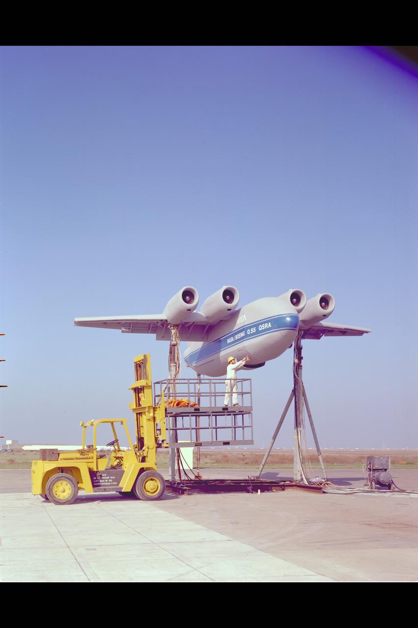
QSRA (Quiet Short-Haul Research Aircraft) S-Duct Test: Static test facility installation (Appeared on the cover of the Avaiation Week & Space Technology on March 21, 1977)
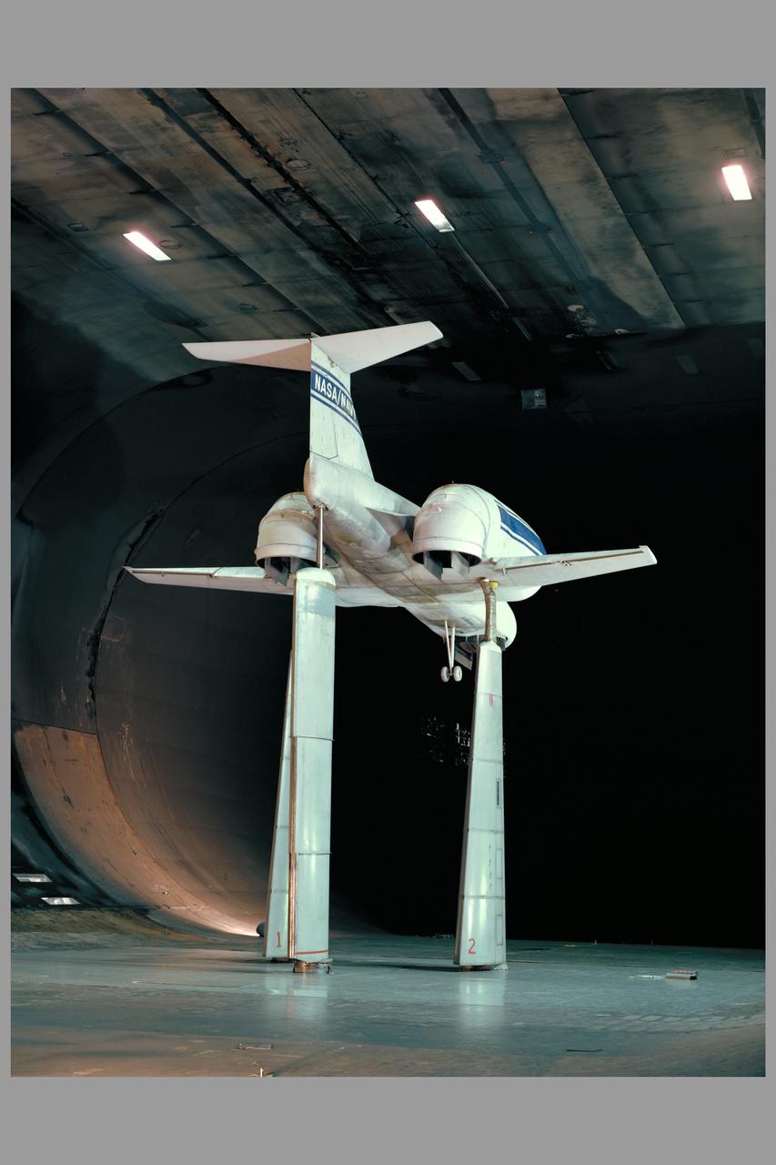
Multi Mission Lift Cruise Fan Model in 40x80ft W.T. Test (Test-490)
Aerodynamics Low cost Oblique Wing Model in 12ft w.t.
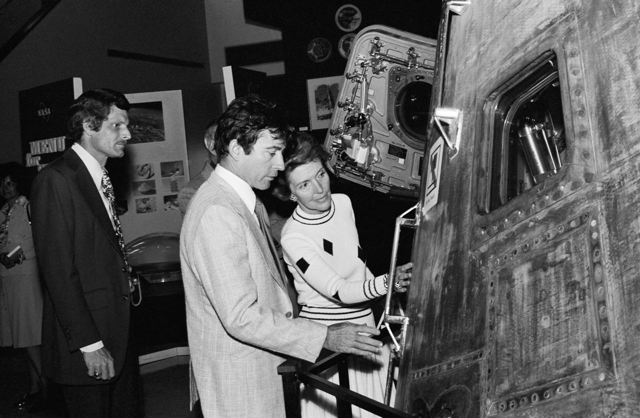
Nine views documenting JSC visit by Mrs. Ronald ( Nancy ) Reagan wife of the U.S, Presidential Candidate challenging the incumbent for Republican nomination. All views are in Building 2. She is seen in Building 2 exhibit area with Astronaut John W. Young in all views and with PAO Harold S. Stall in several. Stall, Young, Reagan at LTA-8 ( 25563 ); Young, Reagan at LRV ( 25564 ); Medium shot of Young, Reagan. ( 25565 ); Young, Reagan at command Module. (25566 ); Reagan, Young, Stall at Cm ( 25567 ); Young, Reagan at Shuttle exhibit. ( 25568 thru 25569 );
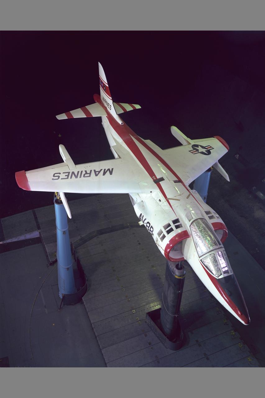
NASA/NAVAIR Marine AV-8B aircraft test-493 in 40x80ft. w.t.
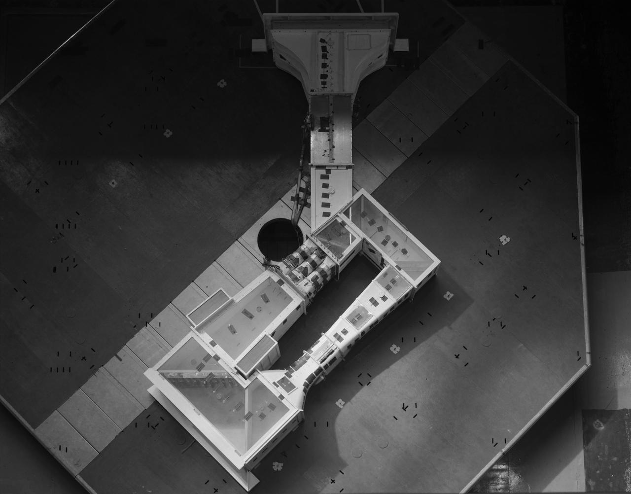
(03/12/1976) Overhead view of 1/50 scale model of the 80x120 foot wind tunnel model (NFAC) in the test section of the 40x80 wind tunnel at NASA Ames. Model mounted on a rotating ground board designed for this test.

A group of Coast Guard seamen leave their ship to verify ice formations on the Great Lakes as part of an joint effort with the National Aeronautics and Space Administration (NASA) Lewis Research Center and the National Oceanic and Atmospheric Administration. The regular winter freezing of large portions of the Great Lakes stalled the shipping industry. Lewis began working on two complementary systems to monitor the ice. The Side Looking Airborne Radar (SLAR) system used microwaves to measure the ice distribution and electromagnetic systems used noise modulation to determine the thickness of the ice. The images were then transferred via satellite to the Coast Guard station. The Coast Guard then transmitted the pertinent images by VHF to the ship captains to help them select the best route. The Great Lakes ice mapping devices were first tested on NASA aircraft during the winter of 1972 and 1973. The pulsed radar system was transferred to the Coast Guard’s C-130 aircraft for the 1975 and 1976 winter. The SLAR was installed in the rear cargo door, and the small S-band antenna was mounted to the underside of the aircraft. Coast Guard flights began in January 1975 at an altitude of 11,000 feet. Early in the program, teams of guardsmen and NASA researchers frequently set out in boats to take samples and measurements of the ice in order to verify the radar information.

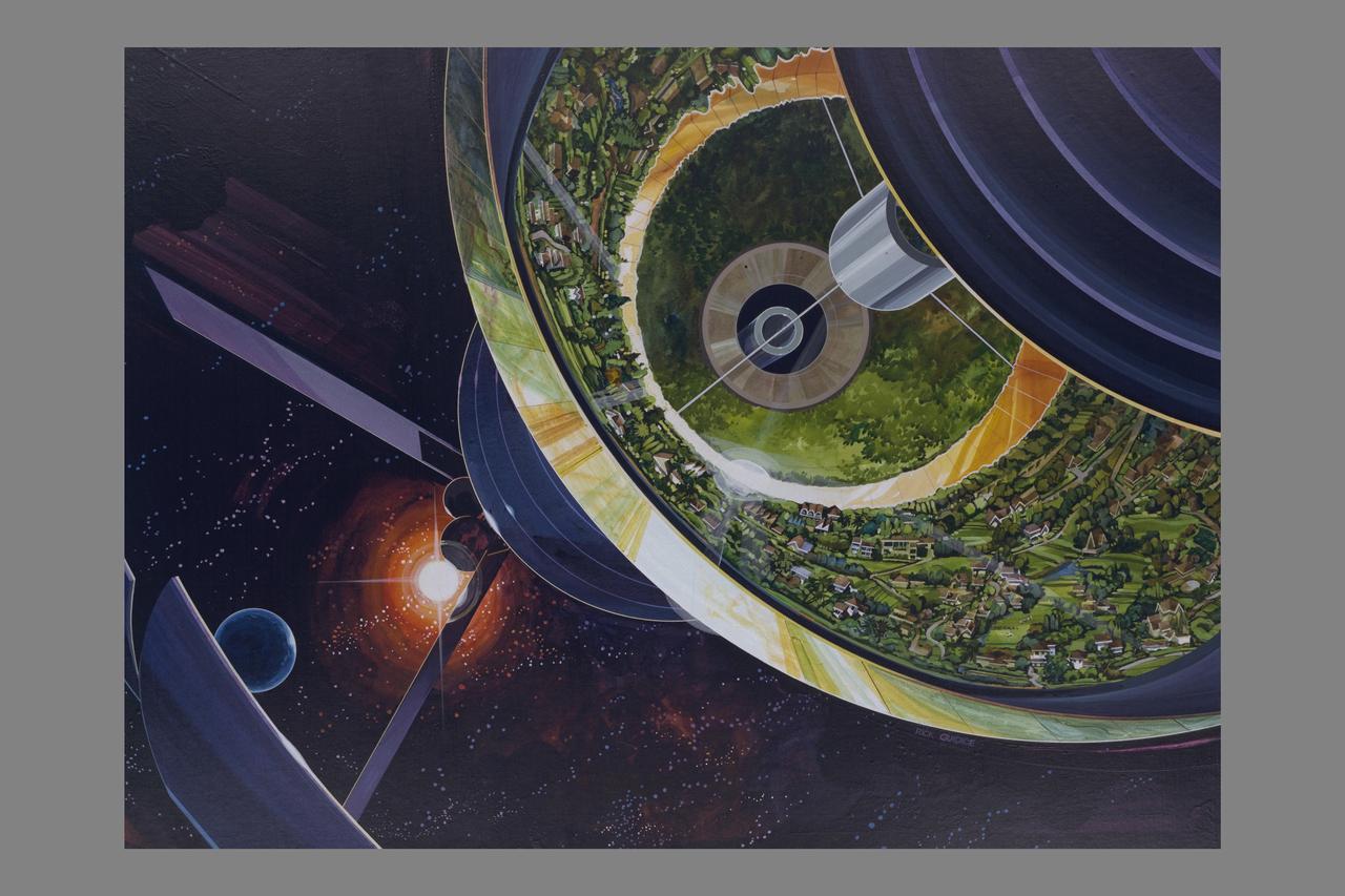
ARTIST: Rick Guidice Space Colonization; inside the sphere gravity is strongest along the equator. as on moves toward the center gravity lessens and one could fly easily. Sunlight enters as shown by the large fuzzy ring. The central tube connects to other sections of the colony.

S76-29557 (17 Sept 1976) --- The two members of the first crew for the Space Shuttle Approach and Landing Tests (ALT) are photographed at the Rockwell International Space Division's Orbiter assembly facility at Palmdale, California on the day of the rollout of the Shuttle Orbiter 101 "Enterprise" spacecraft. They are Astronauts Fred W. Haise Jr. (left), commander; and C. Gordon Fullerton, pilot. The DC-9 size airplane-like Orbiter 101 is in the background.
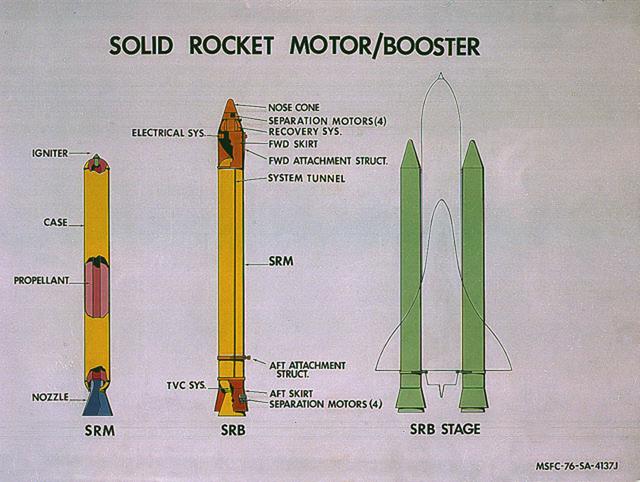
This image illustrates the solid rocket motor (SRM)/solid rocket booster (SRB) configuration. The Shuttle's two SRB's are the largest solids ever built and the first designed for refurbishment and reuse. Standing nearly 150-feet high, the twin boosters provide the majority of thrust for the first two minutes of flight, about 5.8 million pounds, augmenting the Shuttle's main propulsion system during liftoff. The major design drivers for the SRM's were high thrust and reuse. The desired thrust was achieved by using state-of-the-art solid propellant and by using a long cylindrical motor with a specific core design that allows the propellant to burn in a carefully controlled marner. At burnout, the boosters separate from the external tank and drop by parachute to the ocean for recovery and subsequent refurbishment. The boosters are designed to survive water impact at almost 60 miles per hour, maintain flotation with minimal damage, and preclude corrosion of the hardware exposed to the harsh seawater environment. Under the project management of the Marshall Space Flight Center, the SRB's are assembled and refurbished by the United Space Boosters. The SRM's are provided by the Morton Thiokol Corporation.
X-14 Aircraft during hover flight tests at VTOL test pad
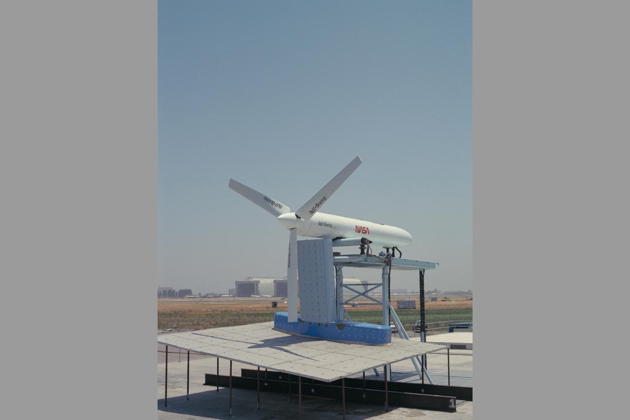
JVX/ATB Rotor Blade Project: Bell Boeing Rotor for the XV-15 tilt rotor Research Aircraft (TRRA)
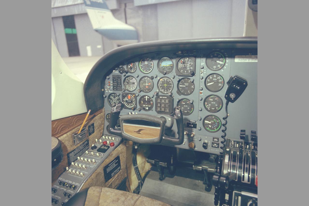
Cessna 402 cockpit
Artist: Rick Guidice Building a Space Colony
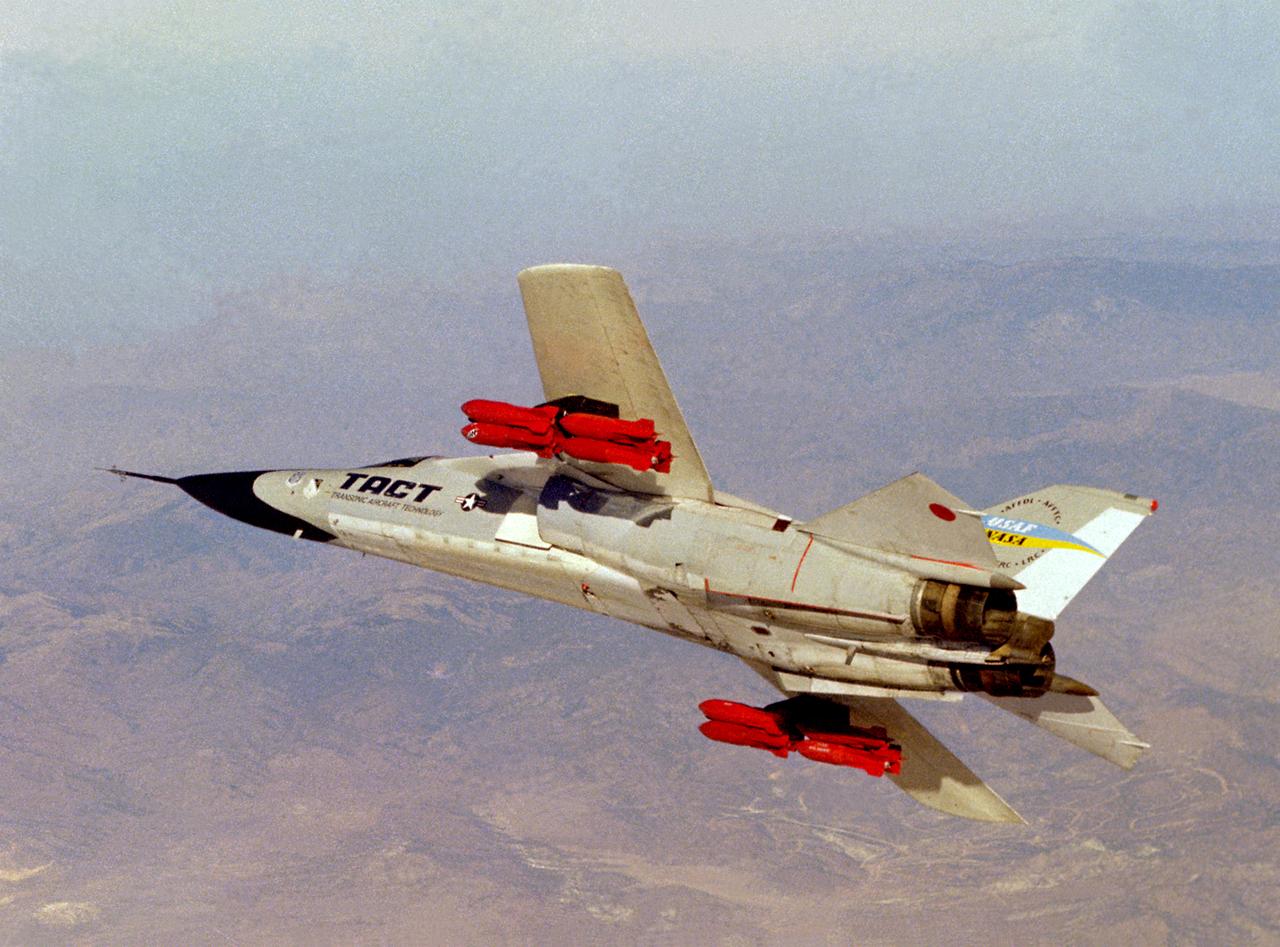
The General Dynamics TACT/F-111A (Serial #63-9778) banks over the Mojave Desert. Note the fully loaded racks of inert pratice bombs which were carried for weapon loads evaluations on the supercritical wing (SCW) that was the main feature of the Transonic Aircraft Technology F-111 research program. Intense interest in the results of the earlier F-8 SCW program spurred NASA and the U.S. Air Force to modify the number 13 F-111A for the TACT program. This aircraft participated in a major research and flight testing program that spanned nearly 20 years, beginning in 1971 at the NASA Flight Research Center at Edwards AFB, California.
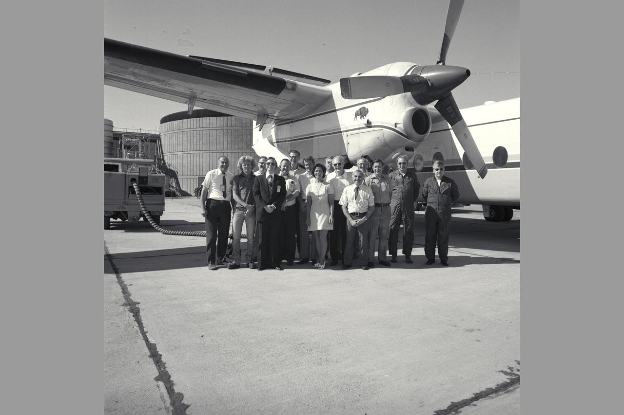
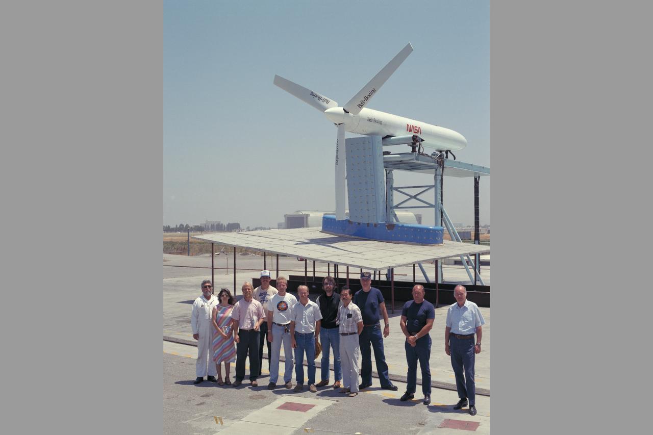
NASA SUPPORT GROUP (QSRA PROJECT TEAM). L-R: John Cochrane, Robert Price, Howard Tuner, Mike Shovlin, Dennis Riddle, Al Boissevain, Dennis Brown, Patty Beck, John Weyers, Bob McCracken, Peter Patterakis, Jack Ratcliff, Al Kass, Bob Innis, Tom Twiggs (Boeing). Note: Used in publication in Flight Research at Ames; 57 Years of Development and Validation of Aeronautical Technology NASA SP-1998-3300 fig. 111
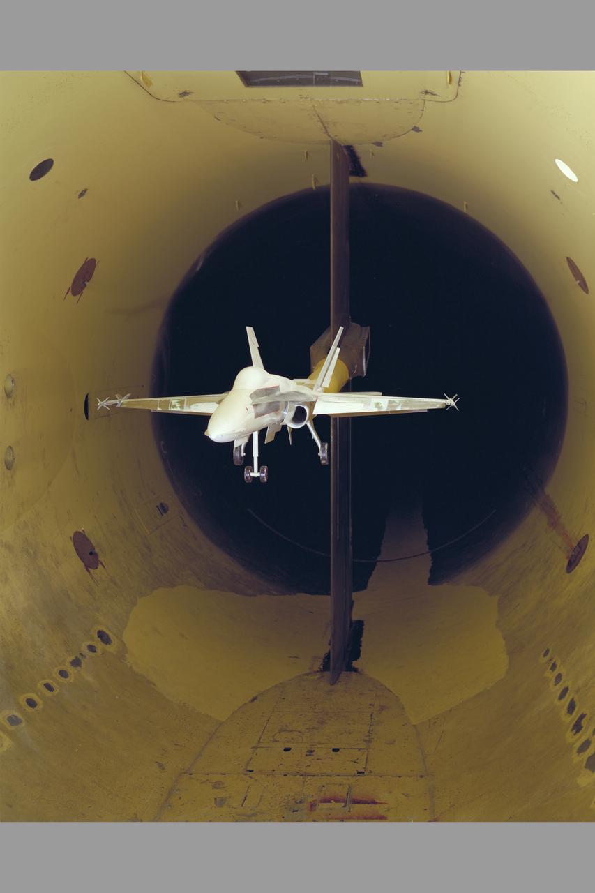
F-18 HICL II model in 12ft w.t.
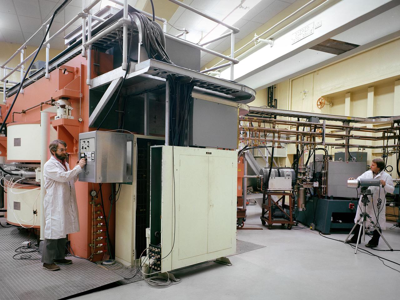
Researchers check the cyclotron in the Materials and Stresses Building at the National Aeronautics and Space Administration (NASA) Lewis Research Center. The Materials and Stresses Building, built in 1949, contained a number of laboratories to test the strength, diffusion, and other facets of materials. The materials could be subjected to high temperatures, high stresses, corrosion, irradiation, and hot gasses. The Physics of Solids Laboratory included a cyclotron, cloud chamber, helium cryostat, and metallurgy cave. The cyclotron was built in the early 1950s to test the effects of radiation on different materials so that the proper materials could be used to construct a nuclear aircraft engine and other components. By the late 1950s, the focus had shifted to similar studies for rockets. NASA cancelled its entire nuclear program in January 1973, and the cyclotron was mothballed. In 1975 the Cleveland Clinic Foundation partnered with NASA Lewis to use the cyclotron to treat cancer patients with a new type of radiation therapy. The cyclotron split beryllium atoms which caused neutrons to be released. The neutrons were streamed directly at the patient’s tumor. Over the course of five years, the cyclotron was used to treat 1200 patients. The program was terminated in 1980 as the Clinic shifted its efforts to concentrate on non-radiation treatments. The Lewis cyclotron was mothballed for a number of years before being demolished.
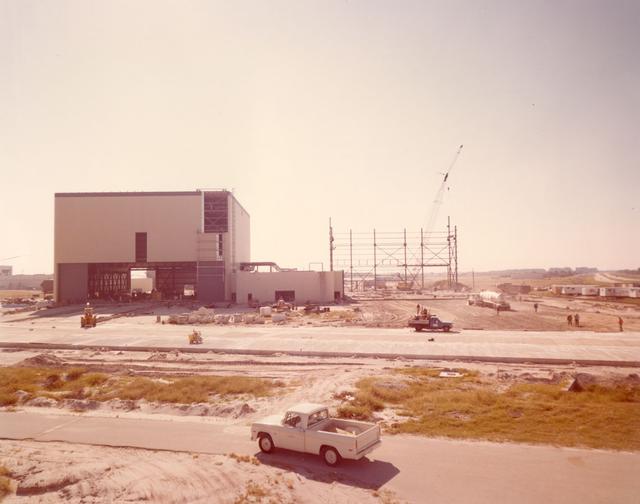
View of OPF High Bay No. 2 construction, 1976
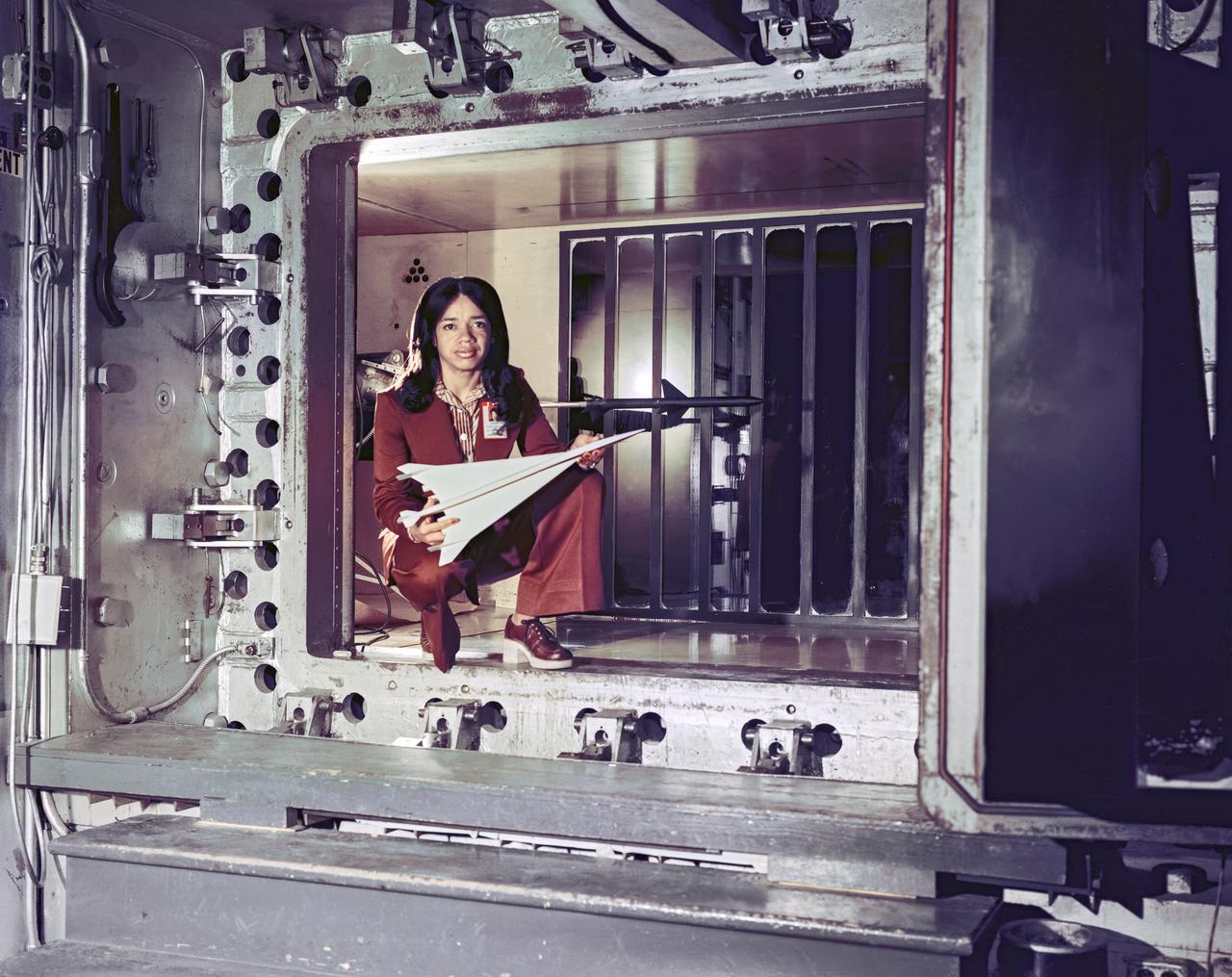
Environmental Portrait of Christine M. Darden. Sonic boom researcher, HSR, High Speed Research
JVX/ATB Rotor Blade Project: Bell Boeing Rotor for the XV-15 tilt rotor Research Aircraft (TRRA) and test crew in front of the OARF
On March 26, 1976, the NASA Flight Research Center opened its doors to hundreds of guests for the dedication of the center in honor of Hugh Latimer Dryden. The dedication was very much a local event; following Center Director David Scott’s opening remarks, the Antelope Valley High School’s symphonic band played the national anthem. Invocation was given followed by recognition of the invited guests. Dr. Hugh Dryden, a man of total humility, received praise from all those present. Dryden, who died in 1965, had been a pioneering aeronautical scientist who became director of the National Advisory Committee for Aeronautics (NACA) in 1949 and then deputy administrator of the NACA’s successor, NASA, in 1958. Very much interested in flight research, he had been responsible for establishing a permanent facility at the location later named in his honor. As Center Director David Scott looks on, Mrs. Hugh L. Dryden (Mary Libbie Travers) unveils the memorial to her husband at the dedication ceremony.On March 26, 1976, the NASA Flight Research Center opened its doors to hundreds of guests for the dedication of the center in honor of Hugh Latimer Dryden.

Artist rendering Torus Sphere. Space Colony Concept. Exterior view of several neighboring colonies. ref: NASA SP-413; Space Settlements: A Design Study
The Ames spirit of free and vigorous discussion; Left to right: Harv Lomax, Leonard Roberts and Harvey Allen during an award ceremony honoring R.T. Jones.
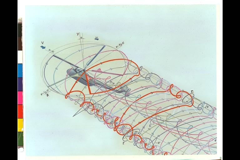
Wake Vortex behind a helicopter (Illustration)
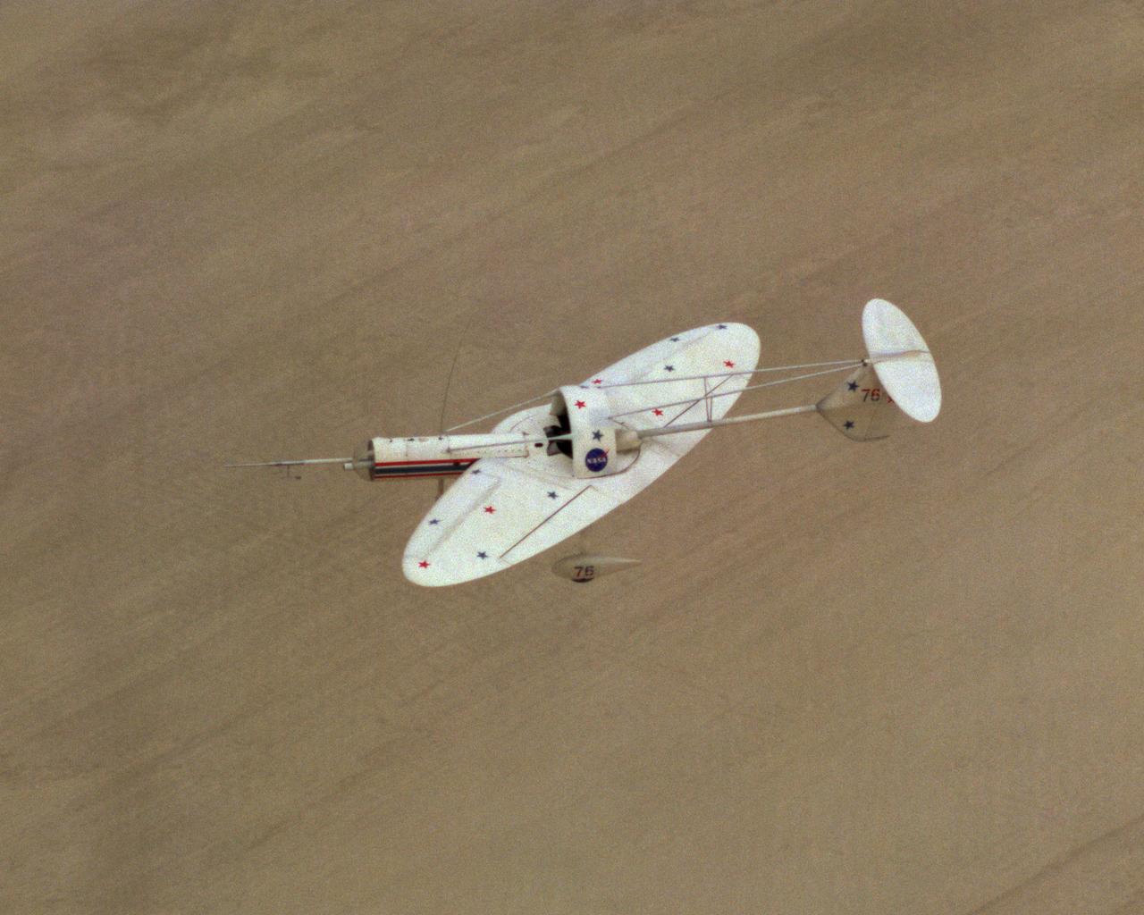
Oblique Wing Research Aircraft in flight
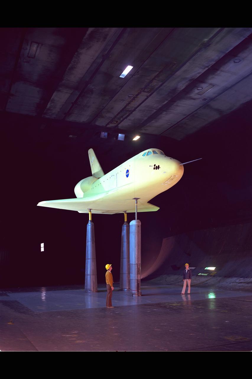
Space Shuttle Vehicle (SSV) 0.36 scale model, 40x80ft w.t. testing
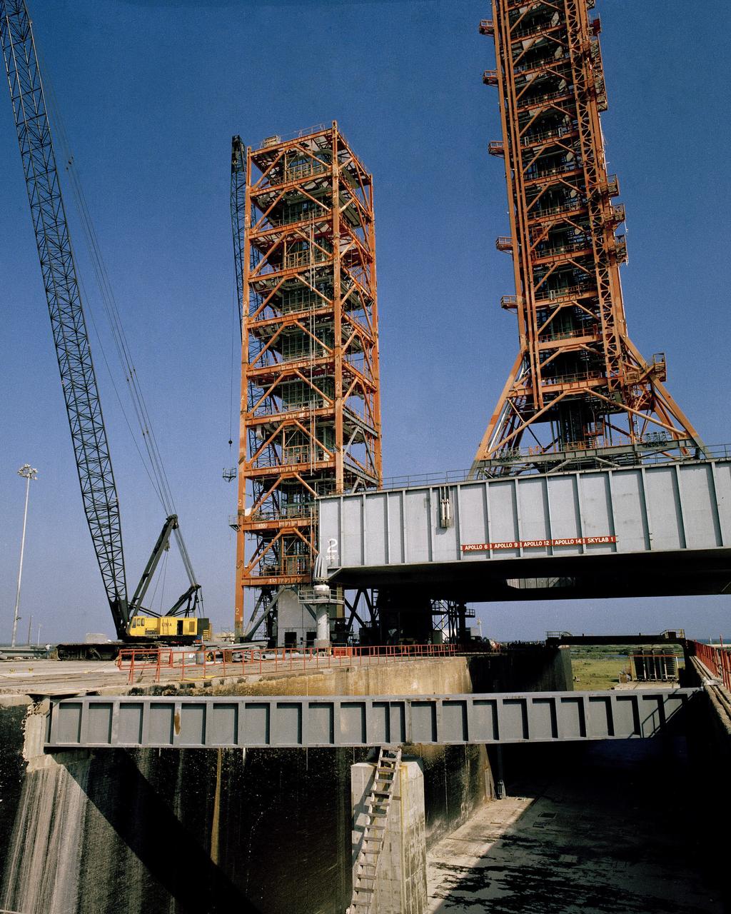
CAPE CANAVERAL, Fla. -- At the Kennedy Space Center in Florida, the shuttle service and access tower SSAT, left, is assembled at Launch Complex 39A from sections of launch umbilical tower 3. The lower 180 feet of the old ML-3 will be topped by the former uppermost section on which a hammerhead crane will be installed and the next lower section which houses the intact ML-3 elevator room and equipment. The SSAT will anchor and support a hinge column to the Payload Changeout Room PCR which will travel on a rail in a specified area to enclose the space shuttle's cargo bay on the pad for installation or removal of payloads. Mobile Launcher 2, center right, is on the pad to support the PCR during construction. Photo Credit: NASA

1/50TH SCALE NFAC MODIFICATION MODEL TESTED IN 40X80FT W.T. (TEST-481) @ Ames Research Center, Moffett Field, CA
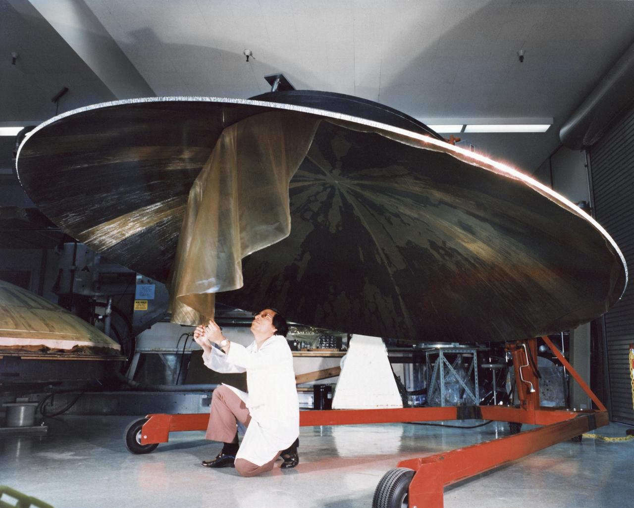
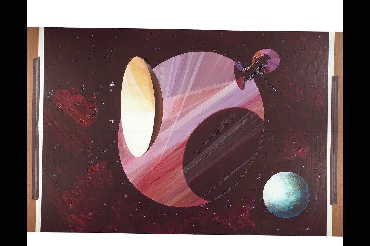
This archival photo shows an engineer working on the construction of a large, dish-shaped Voyager high-gain antenna. The picture was taken on July 9, 1976. https://photojournal.jpl.nasa.gov/catalog/PIA21480
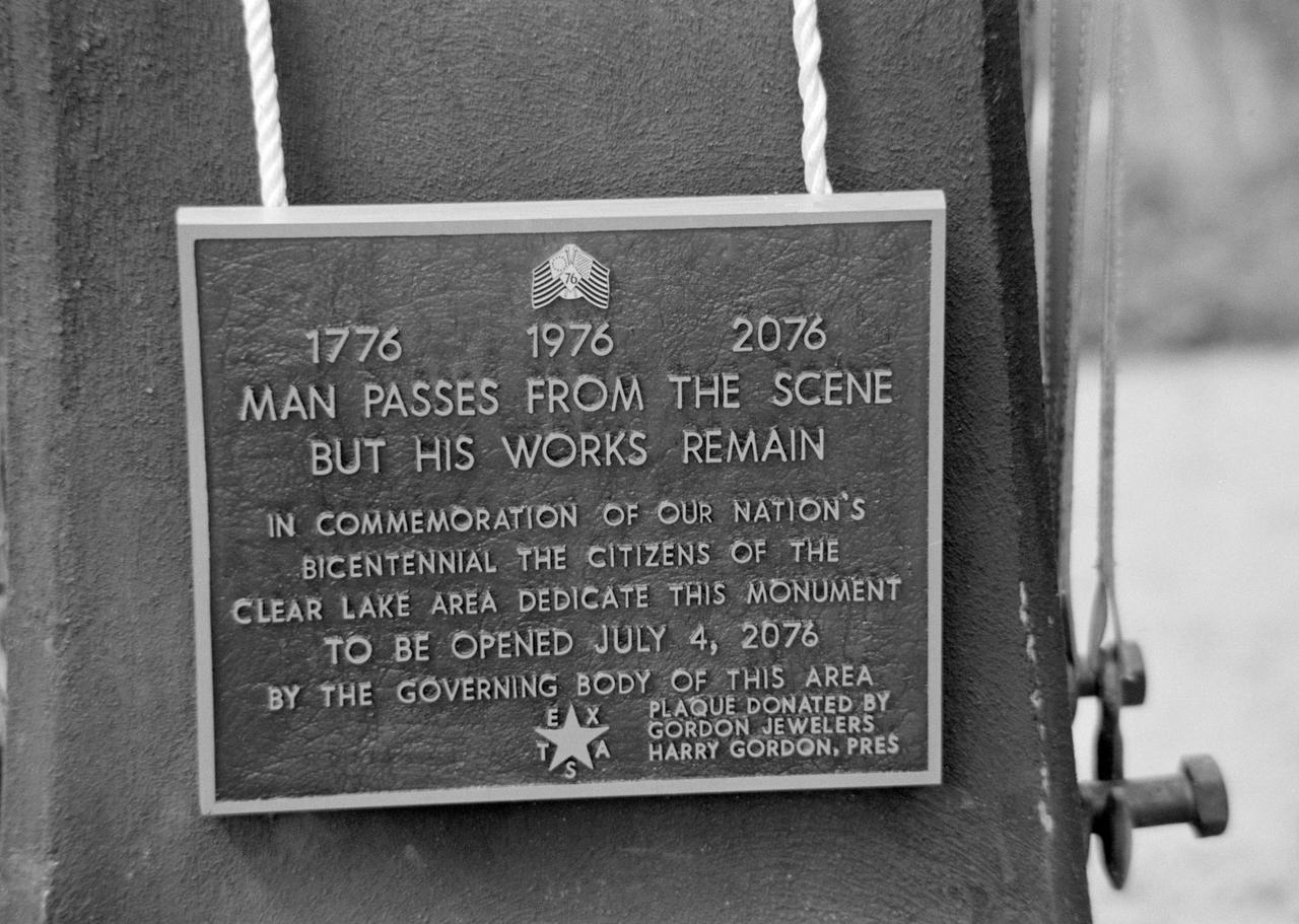
Twenty (20) views of NASA/JSC officials and University officials participating in dedication of University of Houston, Clear Lake campus. HOUSTON, TX
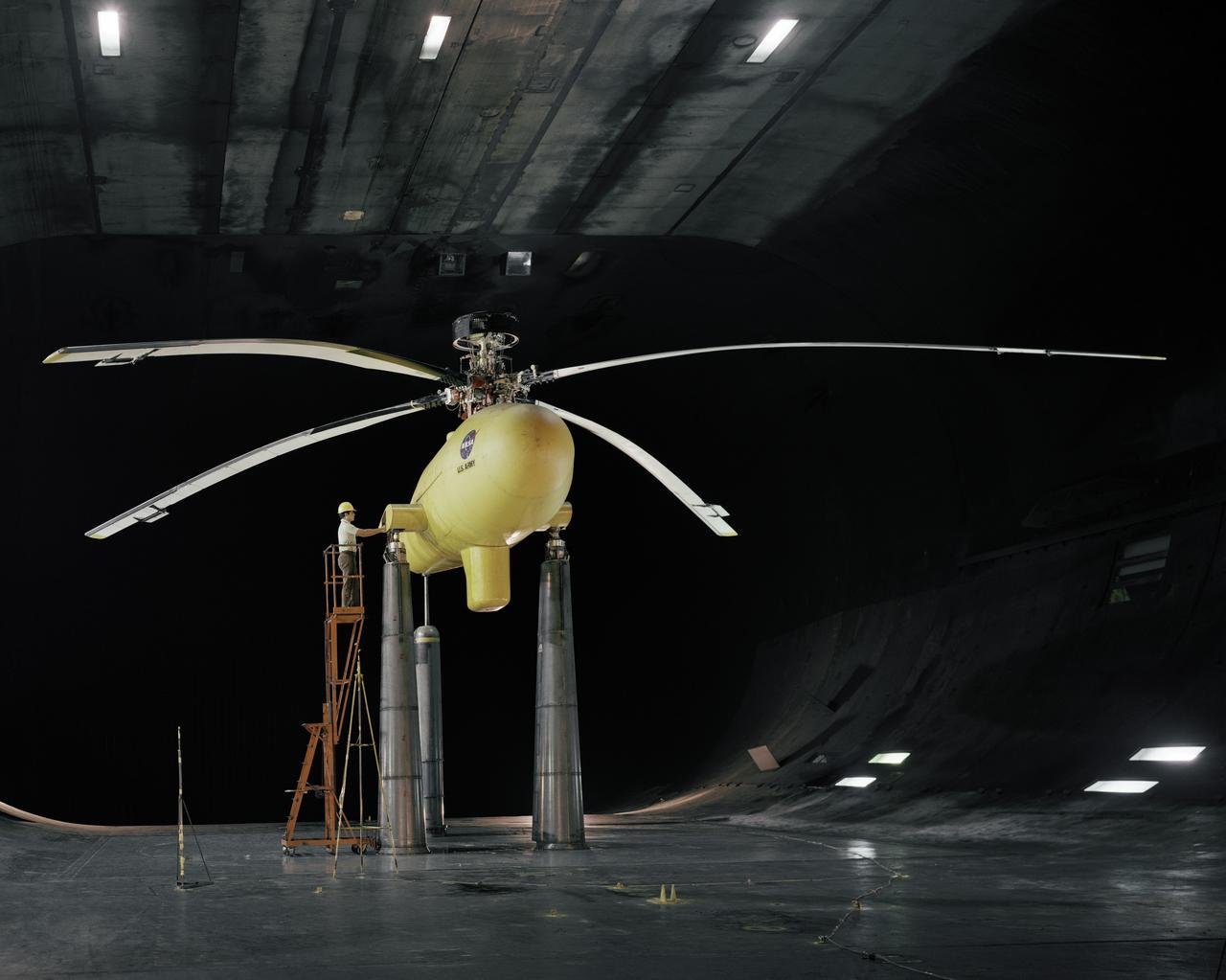
NASA/US Army Multcyclic test rotor in the Ames 40x80ft. Subsonic Wind Tunnel, Ames Research Center, Moffett Field, CA with John Bouldt.
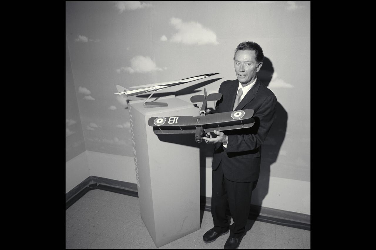
R.T. Jones with models
S76-29569 --- Astronaut Richard H. Truly, pilot of the second crew for the Space Shuttle Approach and Landing Tests (ALT), is photographed at the Rockwell International Space Division's Orbiter assembly facility at Palmdale, California on the day of the rollout of the Shuttle Orbiter 101 "Enterprise" spacecraft. The DC-9 size airplane-like Orbiter 101 is in the background.
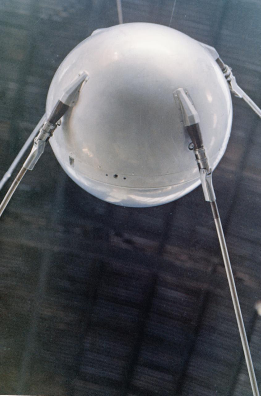
S76-22361 (June 1975) --- A close-up view of the full-scale mockup of the Sputnik 1 spacecraft on display at the Soviet Pavilion at the Paris Air Show, France. Photo credit: NASA or National Aeronautics and Space Administration

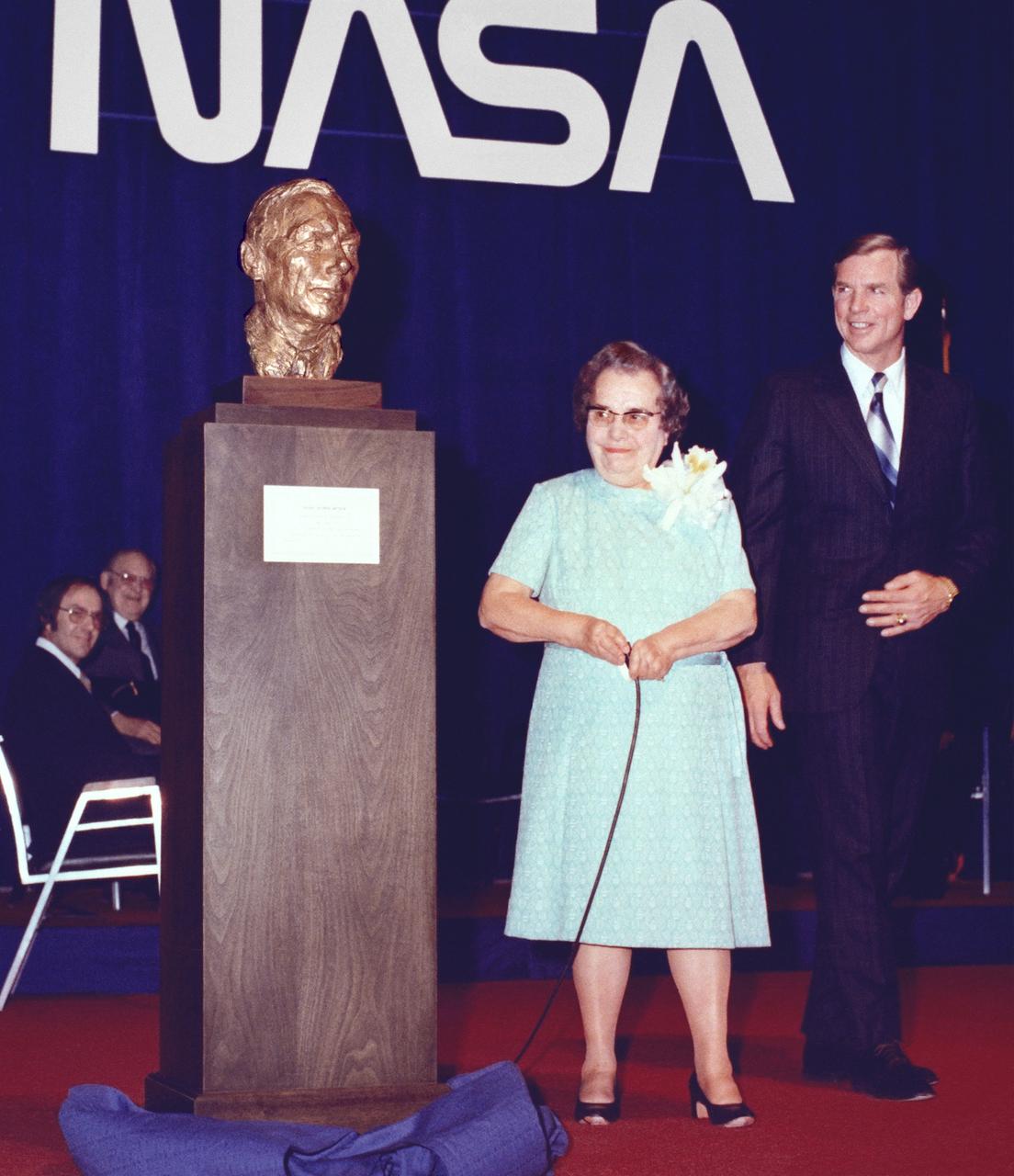
A metal strap became tangled over one of the folded solar array panels when Skylab lost its micro meteoroid shield during its launch. Cutters like the ones used to free the solar array were used to cut the ribbon opening to the public a new full-scale Skylab cluster exhibit at the Alabama Space and Rocket Center in Huntsville, Alabama. Wielding the cutters are (left to right): Alabama Senator James B. Allen; Marshall Space Flight Center director, Dr. William R. Lucas, Huntsville Mayor, Joe Davis; Madison County Commission Chairman, James Record (standing behind Mayor Davis); and chairman of the Alabama Space Science Exhibit Commission, Jack Giles. Astronauts Conrad and Kerwin used the same type of tool in Earth orbit to cut the aluminum strap which jammed the Skylab solar array.
S76-30340 (1976) --- This circular, red, white and blue emblem has been chosen as the official insignia for the Space Shuttle Approach and Landing Test (ALT) flights. A picture of the Orbiter 101 "Enterprise" is superimposed over a red triangle, which in turn is superimposed over a large inner circle of dark blue. The surnames of the members of the two ALT crews are in white in the field of blue. The four crew men are astronauts Fred W. Haise Jr., commander of the first crew; Joe H. Engle, commander of the second crew; and Richard H. Truly, pilot of the second crew. ALT is a series of flights with a modified Boeing 747 Shuttle Carrier Aircraft (SCA) as a ferry aircraft and airborne launch platform for the 67,300 kilogram (75-ton) "Enterprise". The Shuttle Orbiter atmospheric testing is in preparation for the first Earth-orbital flights scheduled in 1979.
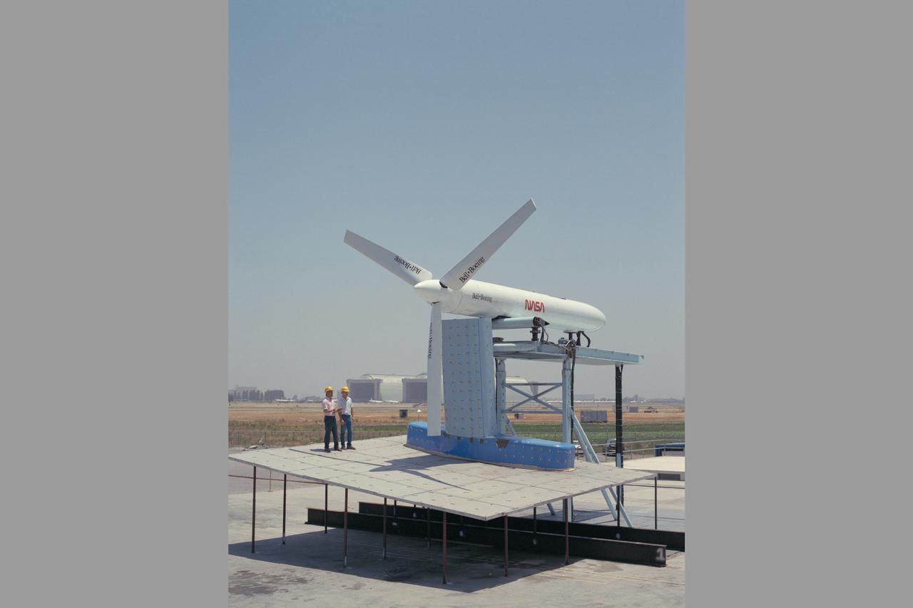
JVX/ATB Rotor Blade Project: Bell Boeing Rotor for the XV-15 tilt rotor Research Aircraft (TRRA)
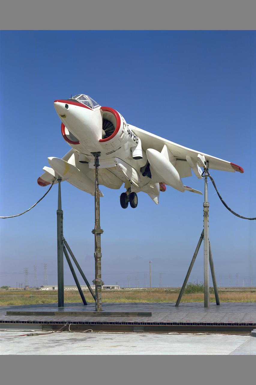
NASA/NAVAIR AV-8B aircraft test-493 at Static Test Stand Facility
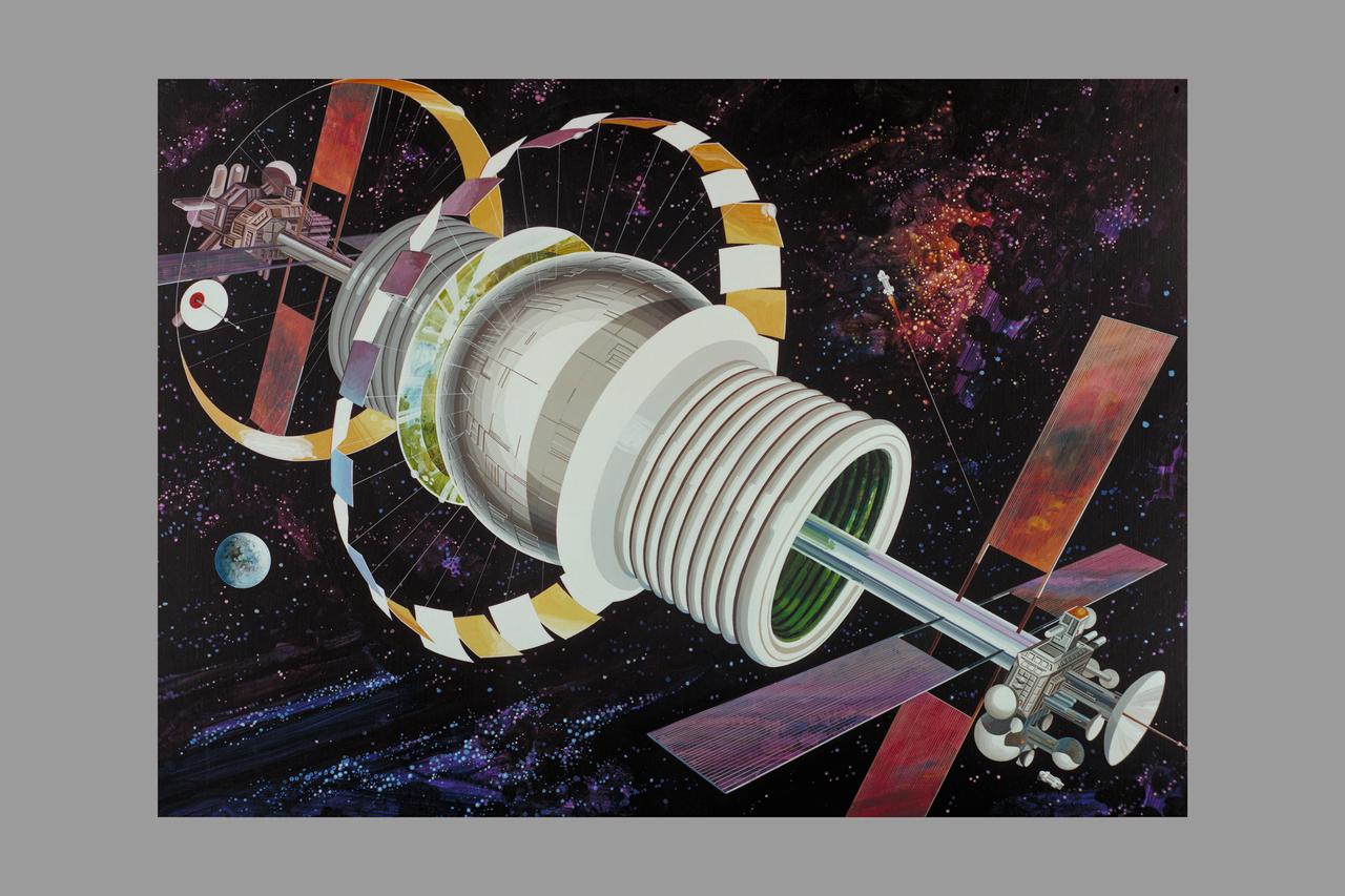
Artist: Rick Guidice Space Colonization - Bernal Sphere - The residential area is in the central sphere. Farming regions are in the 'tires.' Mirrors reflect sunlight into the habitat and farms. The large flat panels radiate away extra heat into space, and panels of solar cells provide electricity. Factories and docks for spaceships are at either end of the long central tube. (NOTE: art printed in Book 'Space Colony - Frontier of the 21st Century by Franklyn M. Branley)
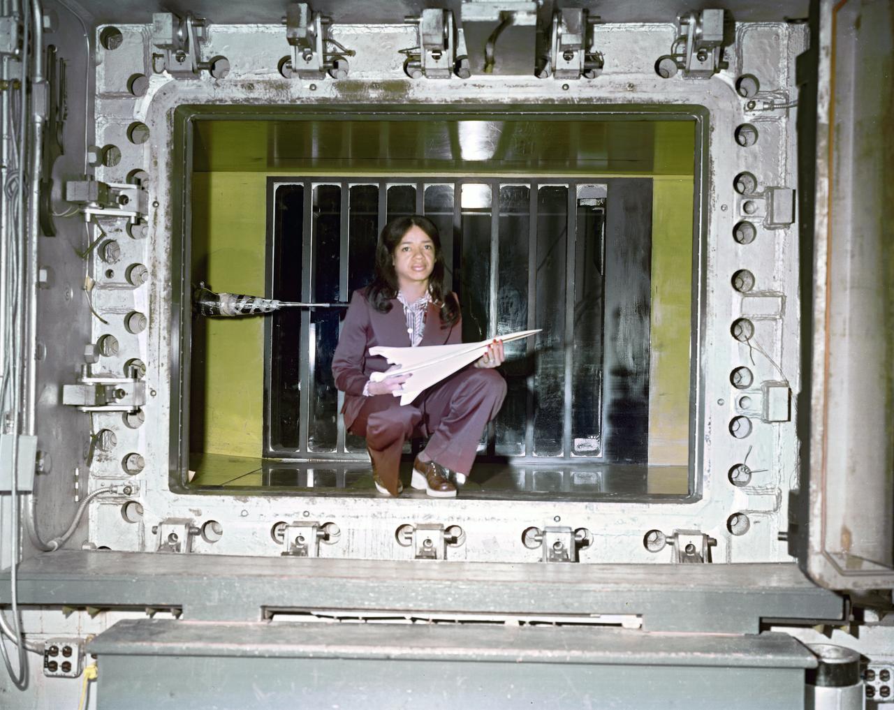
Environmental Portrait of Christine M. Darden. Sonic boom researcher, HSR, High Speed Research
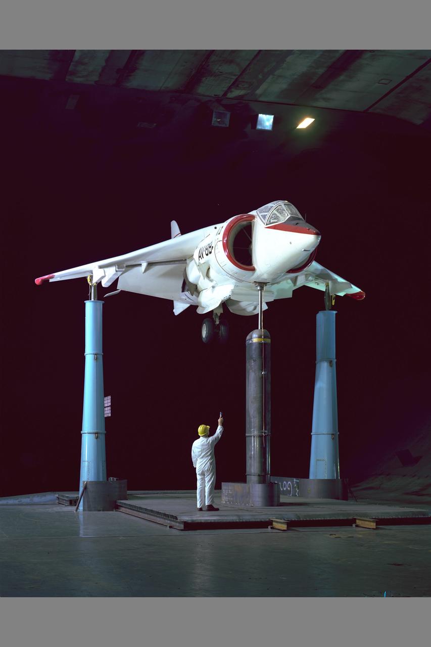
NASA/NAVAIR Marine AV-8B aircraft test-493 in 40x80ft. w.t.
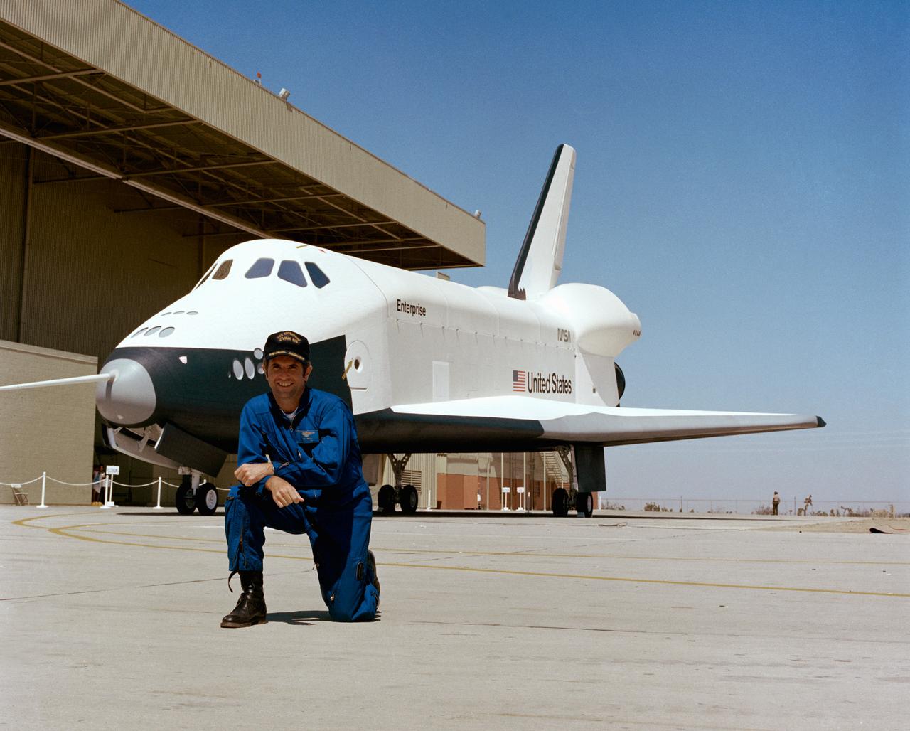
S76-29560 (17 Sept 1976) - - - Astronaut Joe H. Engle, commander of the second crew for the Space Shuttle Approach and Landing Tests (ALT), is photographed at the Rockwell International Space Division?s Orbiter assembly facility at Palmdale, California on the day of the roll out of the Space Shuttle Orbiter 101 ?Enterprise? spacecraft. The DC-size airplane-like Orbiter 101 is in the background.

The National Aeronautics and Space Administration (NASA) Lewis Research Center acquired this Gulfstream C-131B Samaritan from the Air Force in July 1976. The center obtained the aircraft to support its current earth resources work. The C-131B is seen here inside the Lewis hangar being refurbished and converted into a flying laboratory. The modifications were led by Lewis Chief of Flight Operations Robert Hogan. The cockpit and cabin were modified and packed with instrumentation. The new equipment included Sideways Looking Airborne Radar (SLAR), geothermal sensors, radar antennas, and an inertial navigation system. In addition, portals were installed underneath the fuselage for cameras and remote sensing equipment. NASA’s C-131B was used to support researchers tracking ice flows on the Great Lakes and in Prudhoe Bay, Alaska. It was also used for the center’s program to determine heating losses in the Cleveland area’s residential and commercial structures. The aircraft was later donated to the University of Georgia.
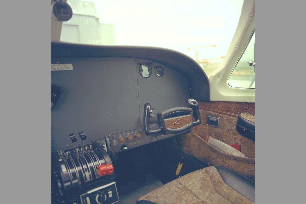
Cessna 402 cockpit

The LAGEOS I (Laser Geodynamics Satellite) was developed and launched by the Marshall Space Flight Center on May 4, 1976 from Vandenberg Air Force Base, California . The two-foot diameter satellite orbited the Earth from pole to pole and measured the movements of the Earth's surface.
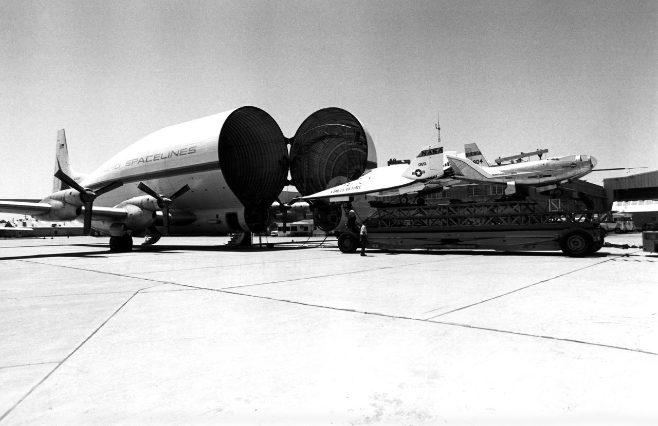
Aero Spacelines B377SGT Super Guppy on Ramp Loading the X-24B and HL-10 Lifting Bodies for Transportation to the Air Force Museum at Wright-Patterson Air Force Base, Ohio

National Aeronautics and Space Administration (NASA) engineer Robert Jeracki prepares a Hamilton Standard SR-1 turboprop model in the test section of the 8- by 6-Foot Supersonic Wind Tunnel at the Lewis Research Center. Lewis researchers were analyzing a series of eight-bladed propellers in their wind tunnels to determine their operating characteristics at speeds up to Mach 0.8. The program, which became the Advanced Turboprop, was part of a NASA-wide Aircraft Energy Efficiency Program which was designed to reduce aircraft fuel costs by 50 percent. The ATP concept was different from the turboprops in use in the 1950s. The modern versions had at least eight blades and were swept back for better performance. After Lewis researchers developed the advanced turboprop theory and established its potential performance capabilities, they commenced an almost decade-long partnership with Hamilton Standard to develop, verify, and improve the concept. A series of 24-inch scale models of the SR-1 with different blade shapes and angles were tested in Lewis’ wind tunnels. A formal program was established in 1978 to examine associated noise levels, aerodynamics, and the drive system. The testing of the large-scale propfan was done on test rigs, in large wind tunnels, and, eventually, on aircraft.

Researcher Susan Johnson and a mechanic examine a flat-plate solar collector in the Solar Simulator Cell in the High Temperature Composites Laboratory at the National Aeronautics and Space Administration (NASA) Lewis Research Center. The Solar Simulator Cell allowed the researchers to control the radiation levels, air temperature, airflow, and fluid flow. The flat-plate collector, seen in a horizontal position here, was directed at the solar simulator, seen above Johnson, during the tests. Lewis researchers were studying the efficiency of various flat- plate solar collector designs in the 1970s for temperature control systems in buildings. The collectors consisted of a cover material, absorber plate, and parallel flow configuration. The collector’s absorber material and coating, covers, honeycomb material, mirrors, vacuum, and tube attachment could all be modified. Johnson’s study analyzed 35 collectors. Johnson, a lifelong pilot, joined NASA Lewis in 1974. The flat-plate solar collectors, seen here, were her first research project. Johnson also investigated advanced heat engines for general aviation and evaluated variable geometry combustors and liners. Johnson earned the Cleveland Technical Society’s Technical Achievement Award in 1984.
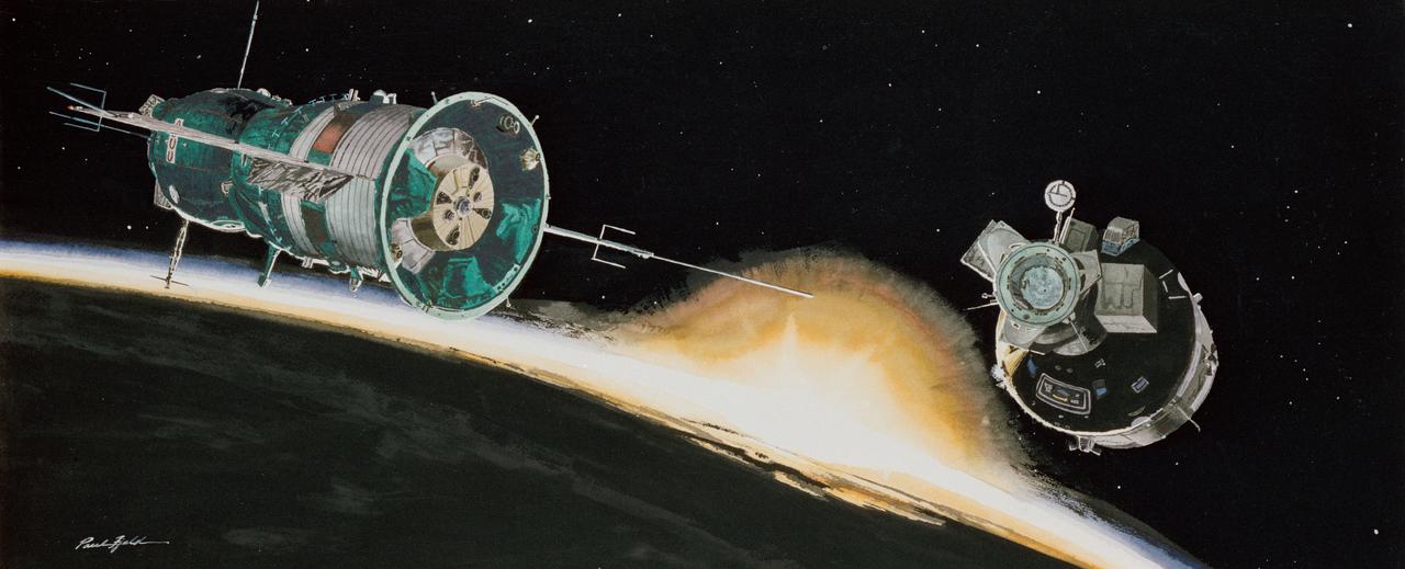
S76-23275 (1976) --- Apollo-Soyuz Test Project artist?s concept by Paul Fjeld.

Wake Vortex behind a helicopter describing Longitudinal Cores (Secondary Vortes Generation) from Aviatsiya / Kosmonautika, 1973 (Illustration)
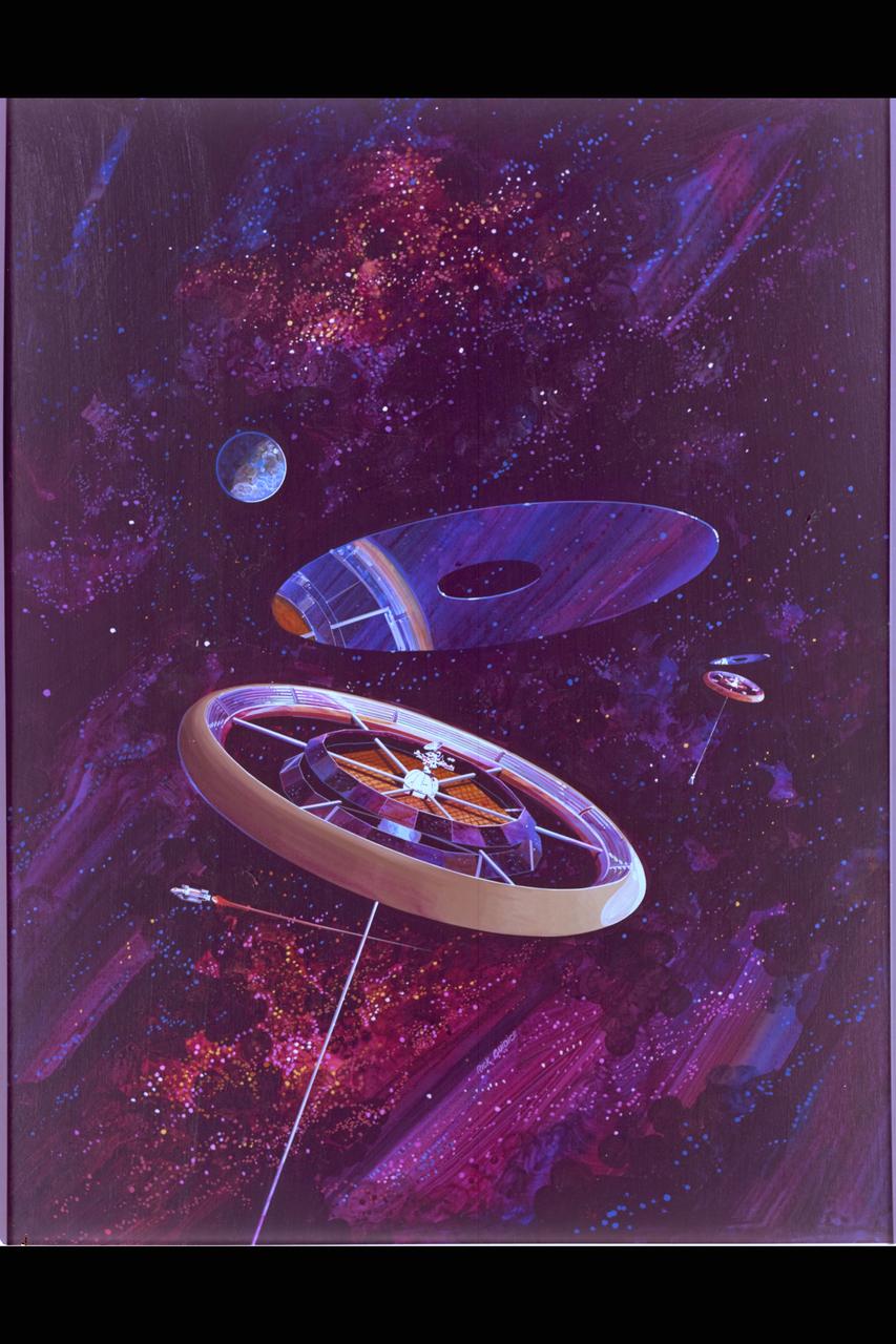
NASA Art by Rick Guidice The Torus Wheel from 'Space Settlements; A Design Study' in colonization sponsored by NASA Ames, ASEE and Stanford University in the summer of 1975 to look at all aspects of sustained life in space. (ref: NASA SP-413, library of congress catalog card number 76-600068)

At its founding, the Marshall Space Flight Center (MSFC) inherited the Army’s Jupiter and Redstone test stands, but much larger facilities were needed for the giant stages of the Saturn V. From 1960 to 1964, the existing stands were remodeled and a sizable new test area was developed. The new comprehensive test complex for propulsion and structural dynamics was unique within the nation and the free world, and they remain so today because they were constructed with foresight to meet the future as well as on going needs. Construction of the S-IC Static test stand complex began in 1961 in the west test area of MSFC, and was completed in 1964. The S-IC static test stand was originally designed to develop and test the 138-ft long and 33-ft diameter Saturn V S-IC first stage, or booster stage. Modifications to the S-IC Test Stand began in 1975 to accommodate space shuttle external tank testing. This photo is of the horizontal liquid oxygen tanks.