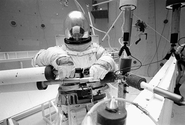
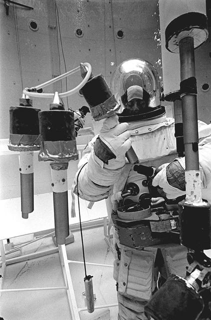
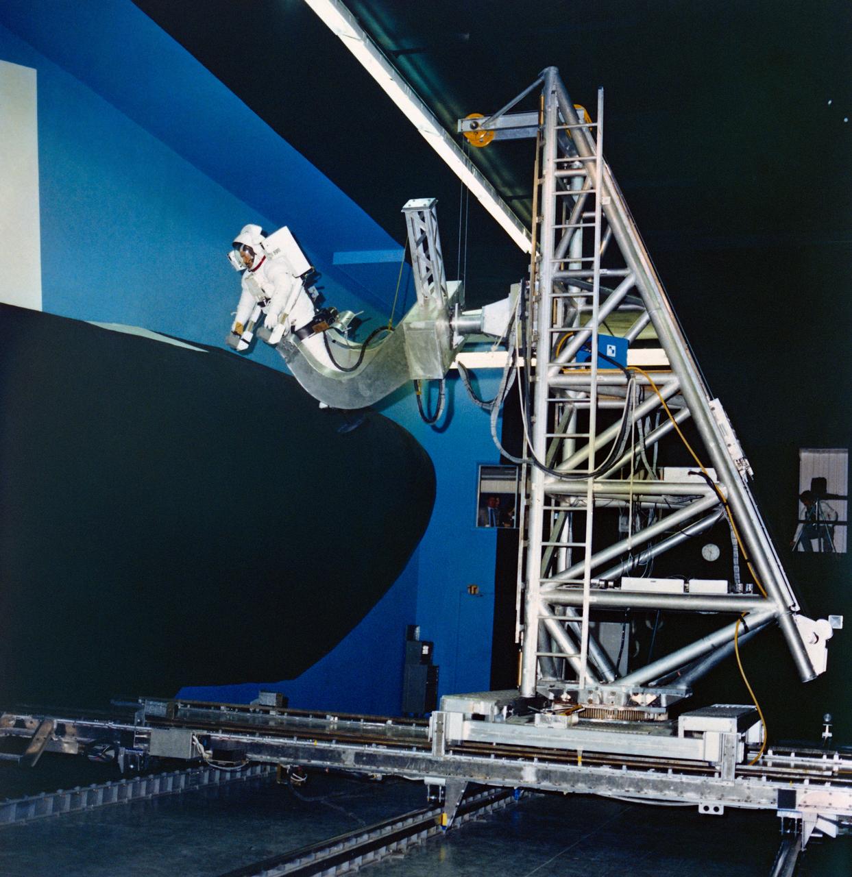
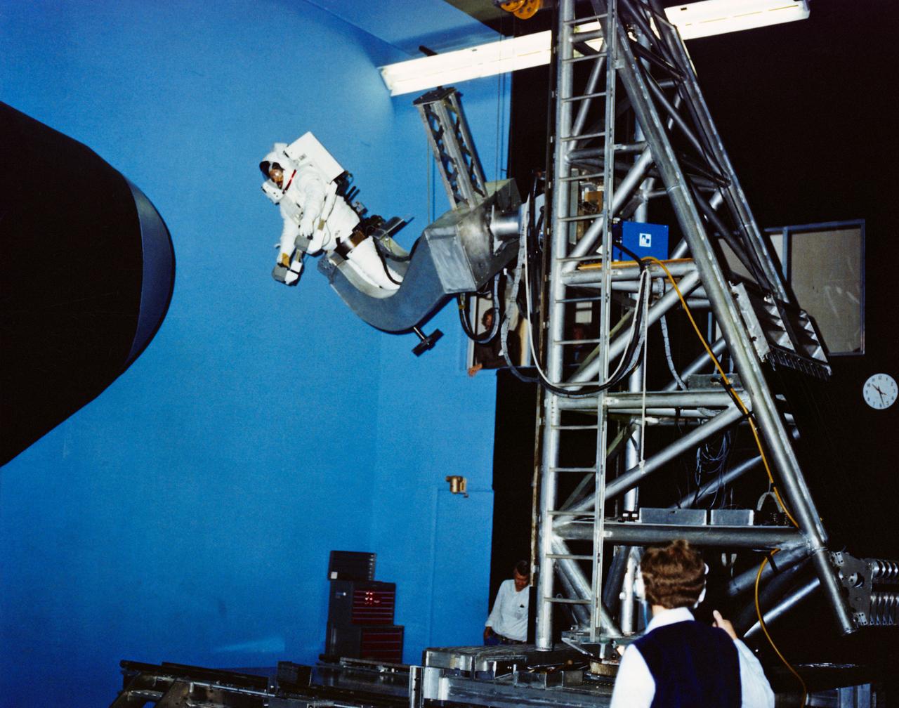
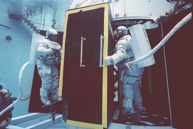
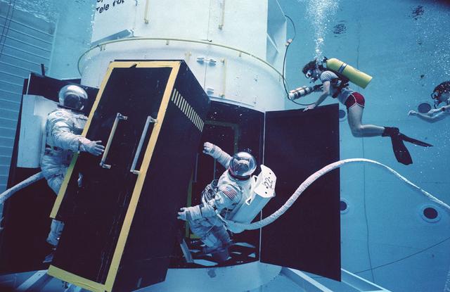
Once the United States' space program had progressed from Earth's orbit into outerspace, the prospect of building and maintaining a permanent presence in space was realized. To accomplish this feat, NASA launched a temporary workstation, Skylab, to discover the effects of low gravity and weightlessness on the human body, and also to develop tools and equipment that would be needed in the future to build and maintain a more permanent space station. The structures, techniques, and work schedules had to be carefully designed to fit this unique construction site. The components had to be lightweight for transport into orbit, yet durable. The station also had to be made with removable parts for easy servicing and repairs by astronauts. All of the tools necessary for service and repairs had to be designed for easy manipulation by a suited astronaut. Construction methods had to be efficient due to the limited time the astronauts could remain outside their controlled environment. In lieu of all the specific needs for this project, an environment on Earth had to be developed that could simulate a low gravity atmosphere. A Neutral Buoyancy Simulator (NBS) was constructed by NASA's Marshall Space Flight Center (MSFC) in 1968. Since then, NASA scientists have used this facility to understand how humans work best in low gravity and also provide information about the different kinds of structures that can be built. Pictured is a Massachusetts Institute of Technology (MIT) student working in a spacesuit on the Experimental Assembly of Structures in Extravehicular Activity (EASE) project which was developed as a joint effort between MFSC and MIT. The EASE experiment required that crew members assemble small components to form larger components, working from the payload bay of the space shuttle. The MIT student in this photo is assembling two six-beam tetrahedrons.
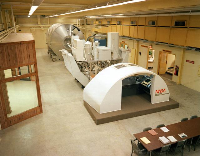
A mockup of the Spacelab II configuration was built at Marshall's Completed Payload Crew Training Complex (PCTC) located at Building 4612.

This supernova in the constellation Cassiopeia was observed by Tycho Brahe in 1572. In this x-ray image from the High Energy Astronomy Observatory (HEAO-2/Einstein Observatory produced by nearly a day of exposure time, the center region appears filled with emissions that can be resolved into patches or knots of material. However, no central pulsar or other collapsed object can be seen. The HEAO-2, the first imaging and largest x-ray telescope built to date, was capable of producing actual photographs of x-ray objects. Shortly after launch, the HEAO-2 was nicknamed the Einstein Observatory by its scientific experimenters in honor of the centernial of the birth of Albert Einstein, whose concepts of relativity and gravitation have influenced much of modern astrophysics, particularly x-ray astronomy. The HEAO-2, designed and developed by TRW, Inc. under the project management of the Marshall Space Flight Center, was launched aboard an Atlas/Centaur launch vehicle on November 13, 1978.
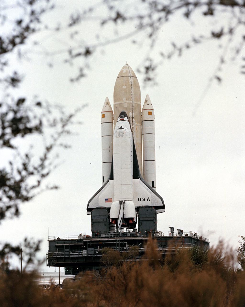
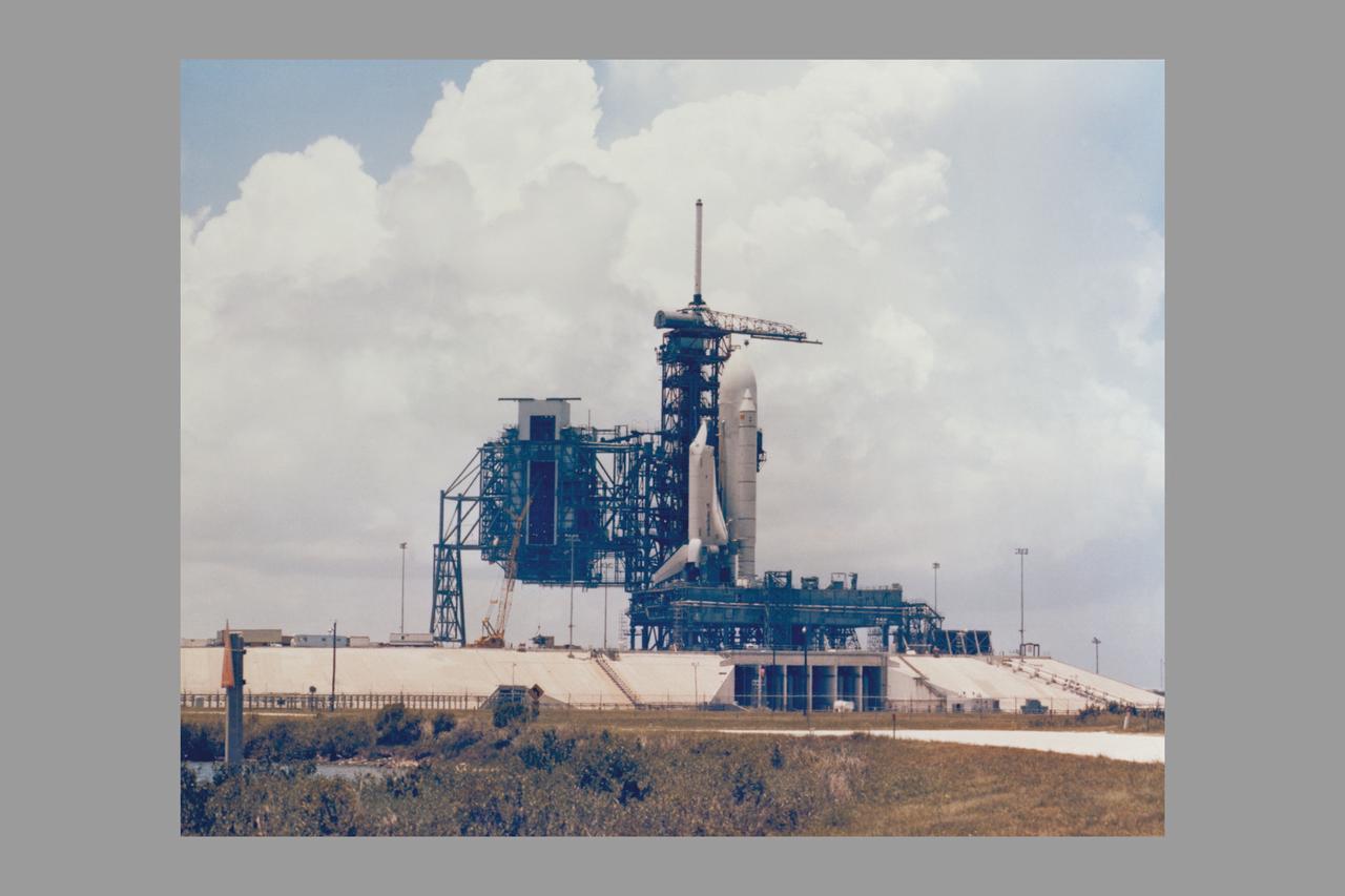
KENNEDY SPACE CENTER, FLA. - STS-1 stands framed in vegetation lining the superhighay-wide crawlerway linking the Vehicle Assembly Building with the twin pads of Launch Complex 39. The first Space Shuttle assembly emerged from the VAB shortly after 8 a.m. today for the 3.5-mile journey to Complex 39's Pad A. The Shuttle was on the hardstand at Pad A approximately seven and a half hours after rollout began. Launch is scheduled for no eariler than March 1981.

CAPE CANAVERAL, Fla. -- AERIALS KSC PAD 39A/B, VAB AND SHUTTLE STRIP, ALTITUDE 11,000 FEET, 270 DEGREES. Photo credit: NASA
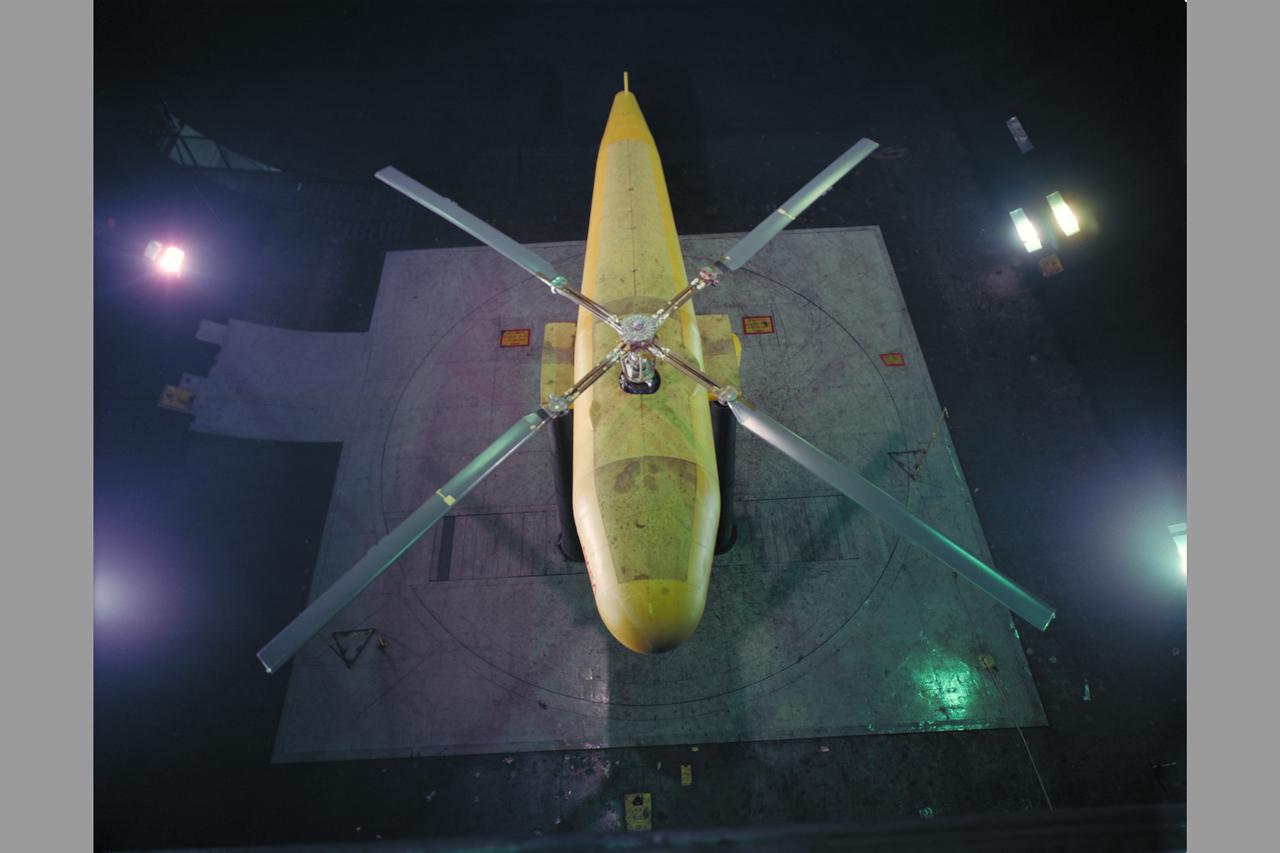
Bearingless Main Rotor
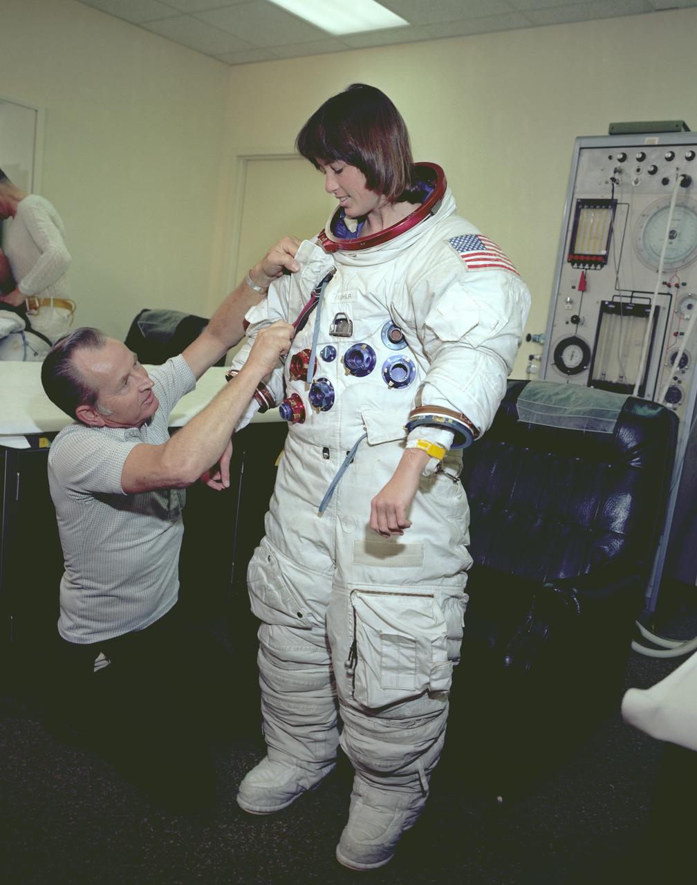
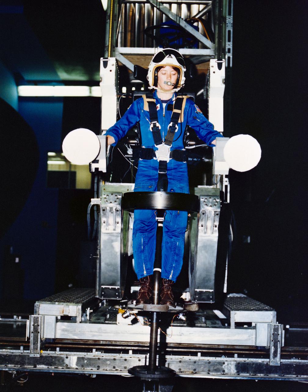
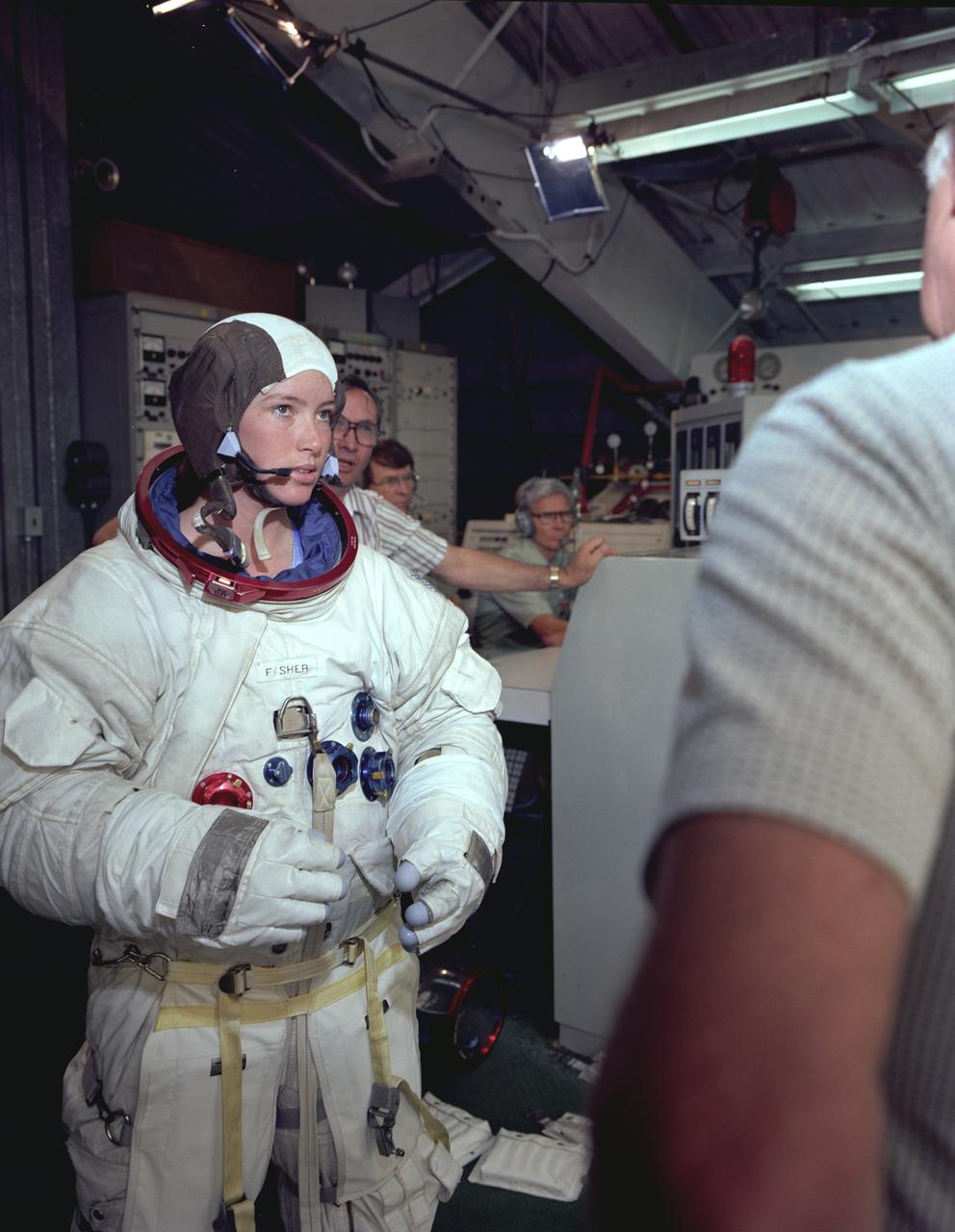
The Hubble Space Telescope (HST) is a cooperative program of the European Space Agency (ESA) and the National Aeronautical and Space Administration (NASA) to operate a long-lived space-based observatory. It was the flagship mission of NASA's Great Observatories program. The HST program began as an astronomical dream in the 1940s. During the 1970s and 1980s, the HST was finally designed and built becoming operational in the 1990s. The HST was deployed into a low-Earth orbit on April 25, 1990 from the cargo bay of the Space Shuttle Discovery (STS-31). The design of the HST took into consideration its length of service and the necessity of repairs and equipment replacement by making the body modular. In doing so, subsequent shuttle missions could recover the HST, replace faulty or obsolete parts and be re-released. Marshall Space Flight Center’s (MSFC's) Neutral Buoyancy Simulator (NBS) served as the test center for shuttle astronauts training for Hubble related missions. Shown is astronaut Anna Fisher suiting up for training on a mockup of a modular section of the HST for an axial scientific instrument change out.
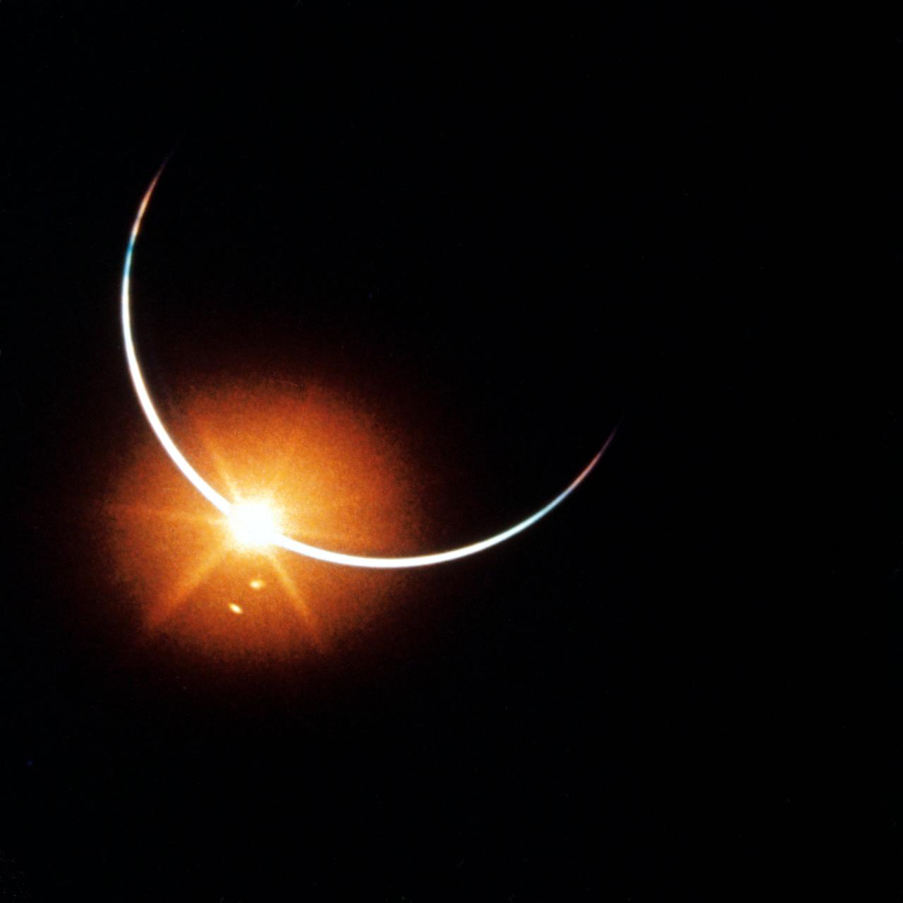
S80-37406 (14-24 Nov. 1969) --- This photograph of the eclipse of the sun was taken with a 16mm motion picture camera from the Apollo 12 spacecraft during its trans-Earth journey home from the moon. The fascinating view was created when the Earth moved directly between the sun and the Apollo 12 spacecraft. Aboard Apollo 12 were astronauts Charles Conrad Jr., commander; Richard F. Gordon Jr., command module pilot; and Alan L. Bean, lunar module pilot. While astronauts Conrad and Bean descended in the Lunar Module (LM) "Intrepid" to explore the Ocean of Storms region of the moon, astronaut Gordon remained with the Command and Service Modules (CSM) "Yankee Clipper" in lunar orbit.
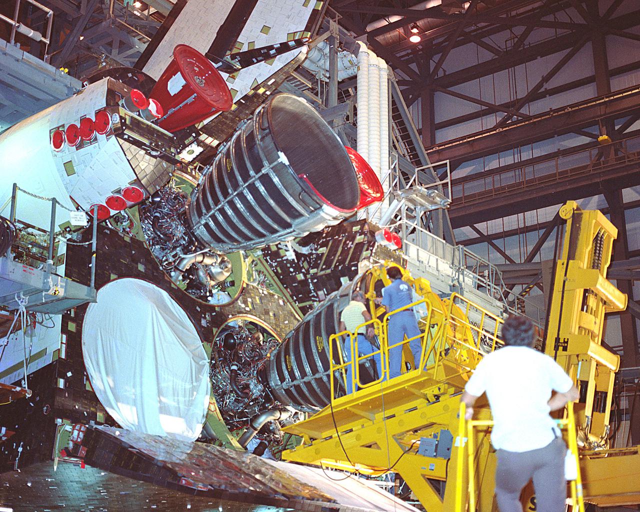
KENNEDY SPACE CENTER, FLA. - Space Shuttle main engines #1 and #3 being installed in Orbiter Columbia.
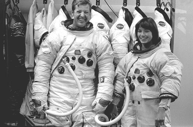
The Hubble Space Telescope (HST) is a cooperative program of the European Space Agency (ESA) and the National Aeronautical and Space Administration (NASA) to operate a long-lived space-based observatory. It was the flagship mission of NASA's Great Observatories program. The HST program began as an astronomical dream in the 1940s. During the 1970s and 1980s, the HST was finally designed and built becoming operational in the 1990s. The HST was deployed into a low-Earth orbit on April 25, 1990 from the cargo bay of the Space Shuttle Discovery (STS-31). The design of the HST took into consideration its length of service and the necessity of repairs and equipment replacement by making the body modular. In doing so, subsequent shuttle missions could recover the HST, replace faulty or obsolete parts and be re-released. Pictured is MSFC's Neutral Buoyancy Simulator (NBS) that served as the test center for shuttle astronauts training for Hubble related missions. Shown are astronauts Arna Fisher and Joe Kerwin training on a mock-up of a modular section of the HST for an axial scientific instrument changeout.
C-141 KAO: CAT equipment

Space Shuttle Simulator cockpit
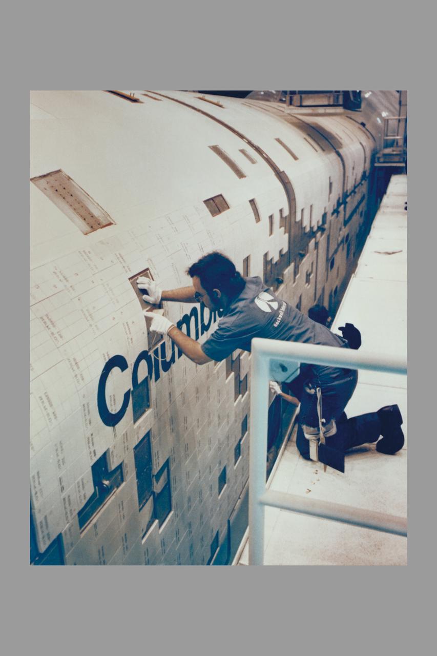
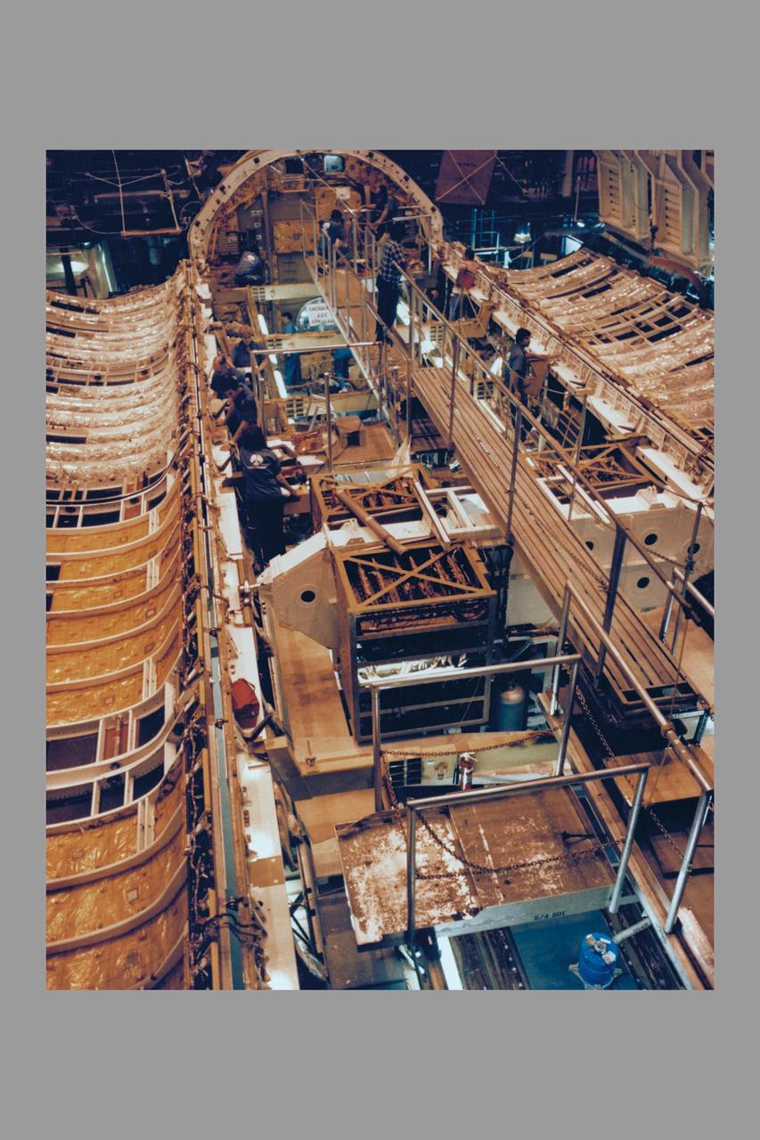
ROCKWELL INTERNATIONAL TECHNICIANS MOUNT SOME OF THE NEARLY 8,000 CERAMIC-COATED TILES THAT REMAIN TO BE INSTALLED ON THE EXTERNAL SURFACES OF THE SPACE SHUTTLE ORBITER COLUMBIA TO COMPLETE THE THERMAL PROTECTION SYSTEM THAT WILL ABSORB THE INTENSE HEAT OF REENTERING THE EARTH'S ATMOSPHERE AFTER A MISSION IN SPACE. TILE INSTALLATION IS DONE ON AN AROUND-THE-CLOCK BASIS IN THE ORBITER PROCESSING FACILITY WHERE COLUMBIA, THE FIRST IN A NEW BREED OF MANNED, REUSABLE SPACECRAFT, IS BEING READIED FOR THE FIRST LAUNCH OF THE SPACE SHUTTLE LATER THIS YEAR.
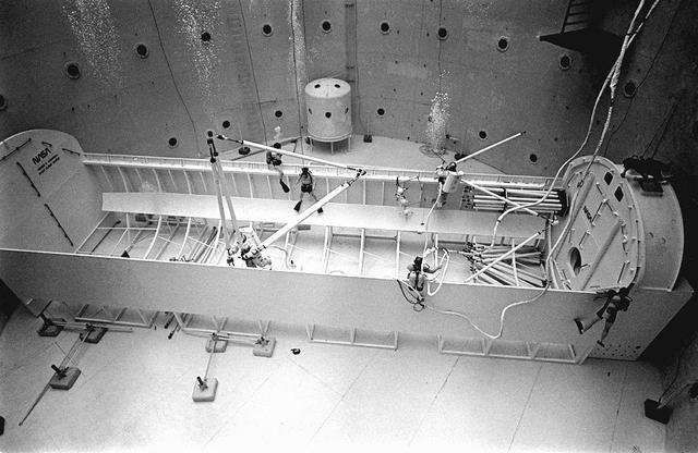
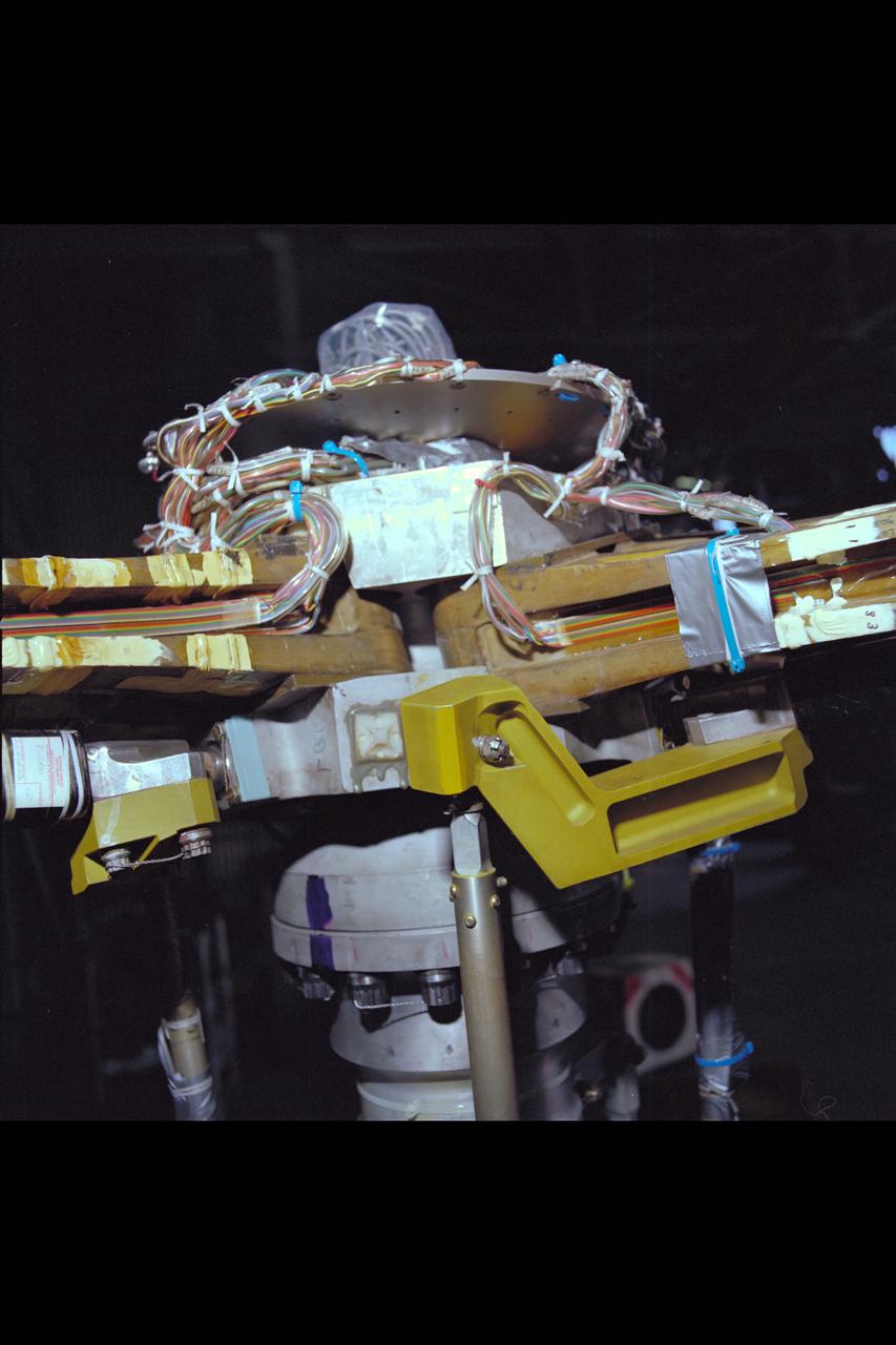
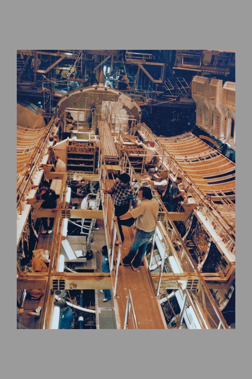
Once the United States' space program had progressed from Earth's orbit into outerspace, the prospect of building and maintaining a permanent presence in space was realized. To accomplish this feat, NASA launched a temporary workstation, Skylab, to discover the effects of low gravity and weightlessness on the human body, and also to develop tools and equipment that would be needed in the future to build and maintain a more permanent space station. The structures, techniques, and work schedules had to be carefully designed to fit this unique construction site. The components had to be lightweight for transport into orbit, yet durable. The station also had to be made with removable parts for easy servicing and repairs by astronauts. All of the tools necessary for service and repairs had to be designed for easy manipulation by a suited astronaut. Construction methods had to be efficient due to the limited time the astronauts could remain outside their controlled environment. In lieu of all the specific needs for this project, an environment on Earth had to be developed that could simulate a low gravity atmosphere. A Neutral Buoyancy Simulator (NBS) was constructed by NASA Marshall Space Flight Center (MSFC) in 1968. Since then, NASA scientists have used this facility to understand how humans work best in low gravity and also provide information about the different kinds of structures that can be built. As part of this experimentation, the Experimental Assembly of Structures in Extravehicular Activity (EASE) project was developed as a joint effort between MFSC and the Massachusetts Institute of Technology (MIT). The EASE experiment required that crew members assemble small components to form larger components, working from the payload bay of the space shuttle. Pictured is an entire unit that has been constructed and is sitting in the bottom of a mock-up shuttle cargo bay pallet.
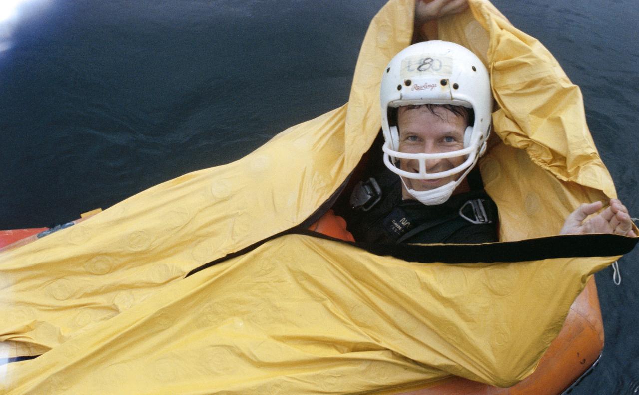
S80-38468 (4 Sept 1980) --- Astronaut Claude Nicollier in water egress training. View is of Nicollier in one-man life raft.
S80-36844 (24 July 1980) --- Manned Maneuvering Unit (MMU) development at the Martin Marietta plant in Denver, Colorado. View shows MMU prototype with astronaut AnnaL. Fisher serving as test subject strapped in to it. Photo credit: NASA
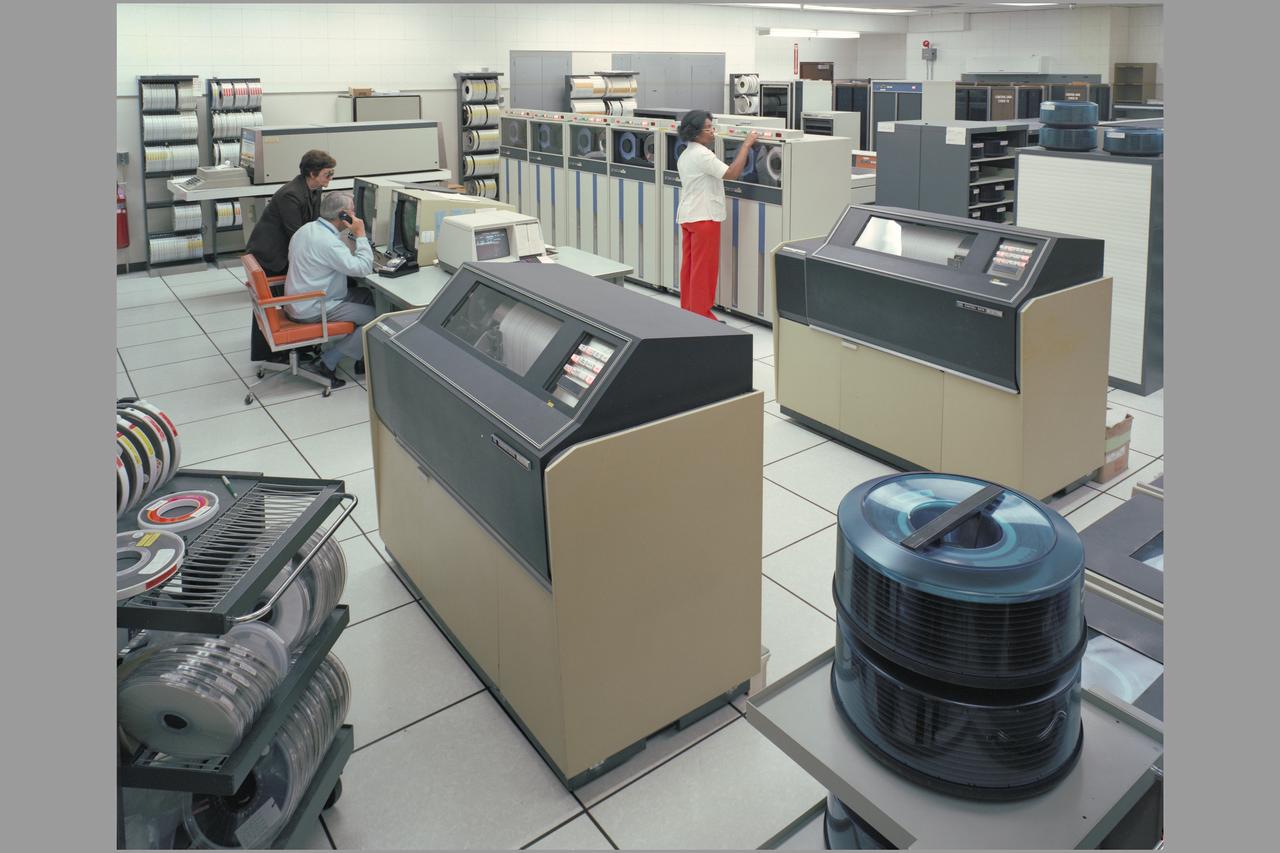
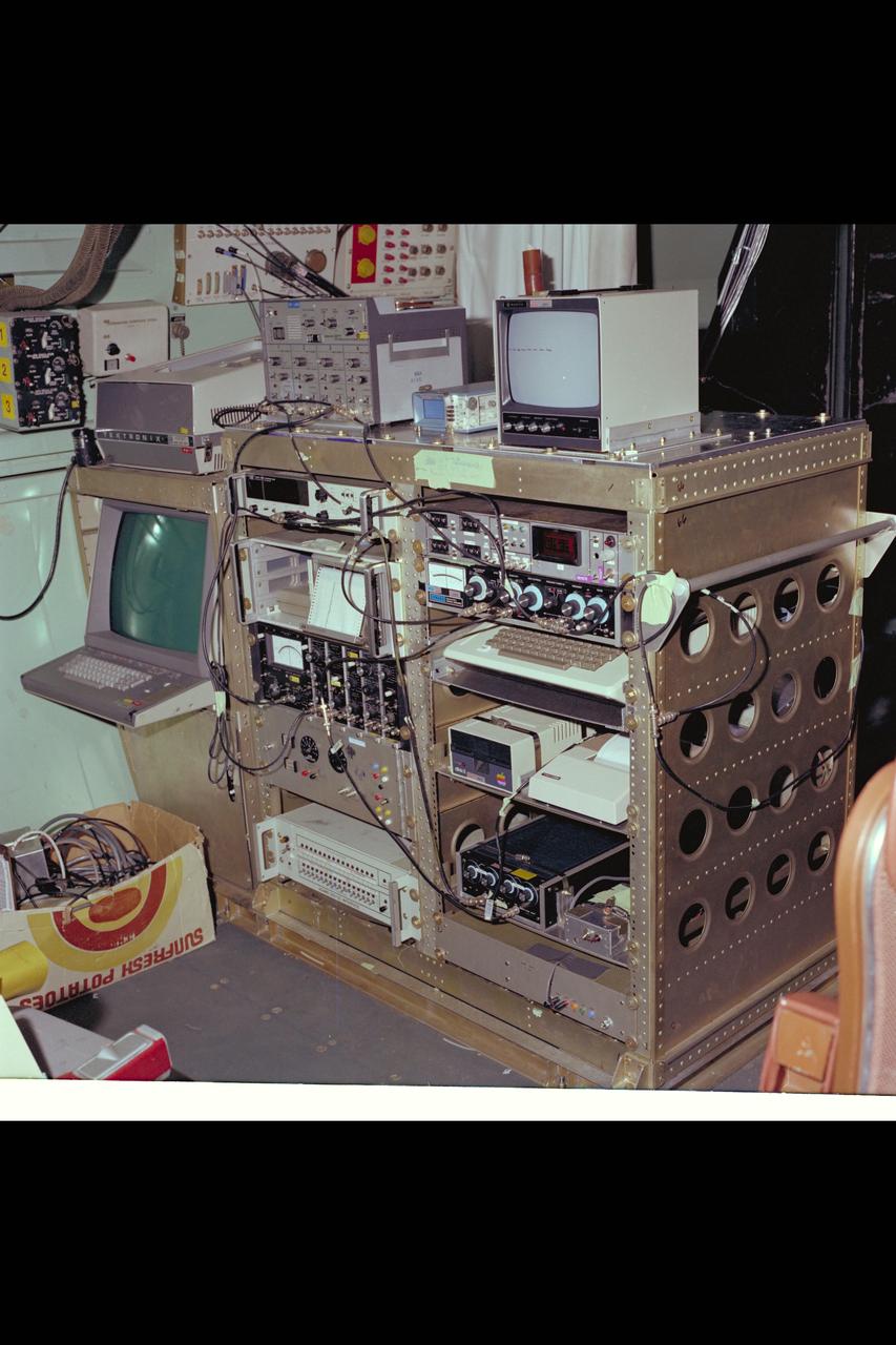
N-233 computer hardware VAX Control Data

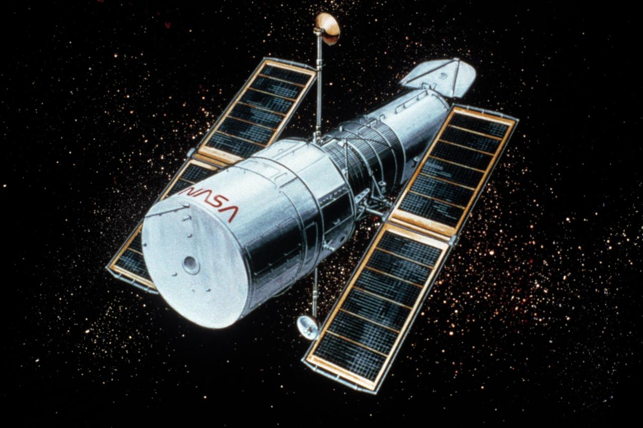
This artist's concept depicts the Hubble Space Telescope after being released into orbit, with the high gain anternas and solar arrays deployed and the aperture doors opened. The HST is the product of a partnership between NASA, European Space Agency Contractors, and the international community of astronomers. It is named after Edwin P. Hubble, an American Astronomer who discovered the expanding nature of the universe and was the first to realize the true nature of galaxies. The purpose of the HST, the most complex and sensitive optical telescope ever made, is to study the cosmos from a low-Earth orbit. By placing the telescope in space, astronomers are able to collect data that is free of the Earth's atmosphere. The HST detects objects 25 times fainter than the dimmest objects seen from Earth and provides astronomers with an observable universe 250 times larger than visible from ground-based telescopes, perhaps as far away as 14 billion light-years. The HST views galaxies, stars, planets, comets, possibly other solar systems, and even unusual phenomena such as quasars, with 10 times the clarity of ground-based telescopes. The major elements of the HST are the Optical Telescope Assembly (OTA), the Support System Module (SSM), and the Scientific Instruments (SI). The HST is 42.5-feet (13-meters) long and weighs about 25,000 pounds (11,600 kilograms). The HST was deployed from the Space Shuttle Discovery (STS-31 mission) into Earth orbit in April 1990. The Marshall Space Flight Center had responsibility for design, development, and construction of the HST. The Perkin-Elmer Corporation, in Danbury, Connecticut, developed the optical system and guidance sensors. The Lockheed Missile and Space Company of Sunnyvale, California produced the protective outer shroud and spacecraft systems, and assembled and tested the finished telescope.
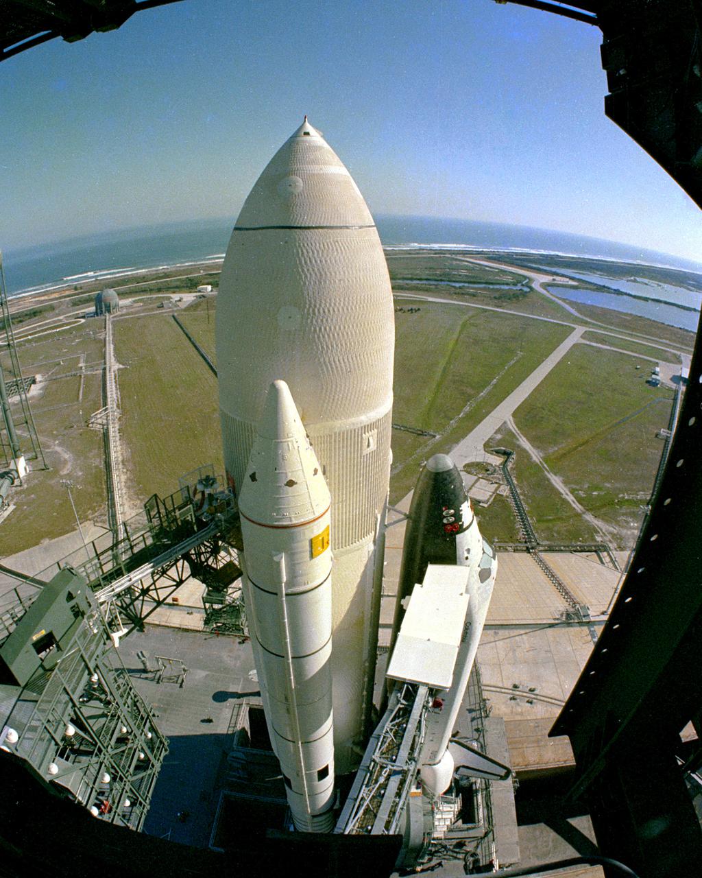
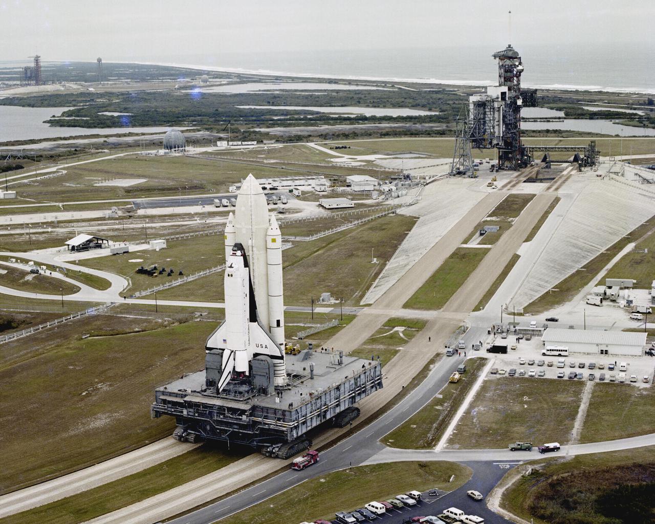
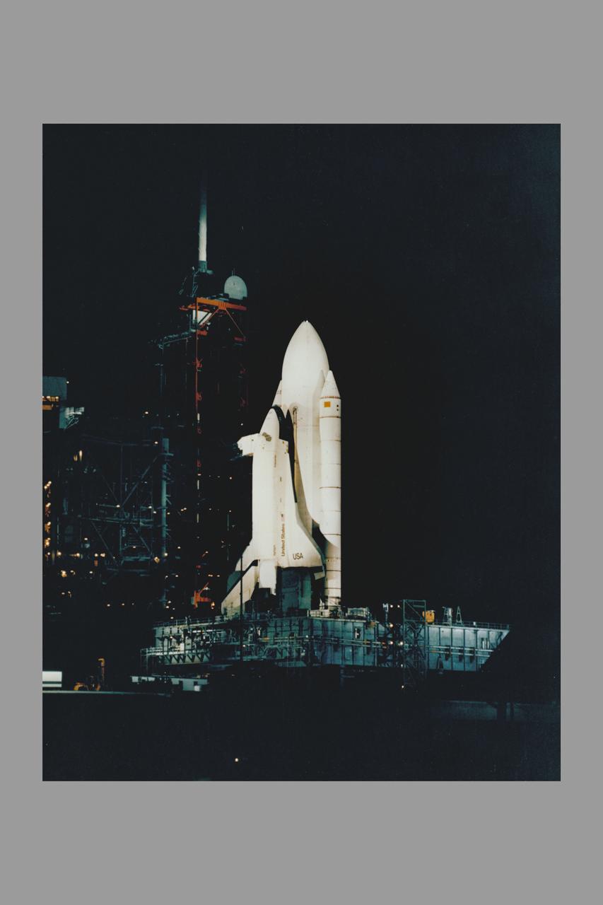
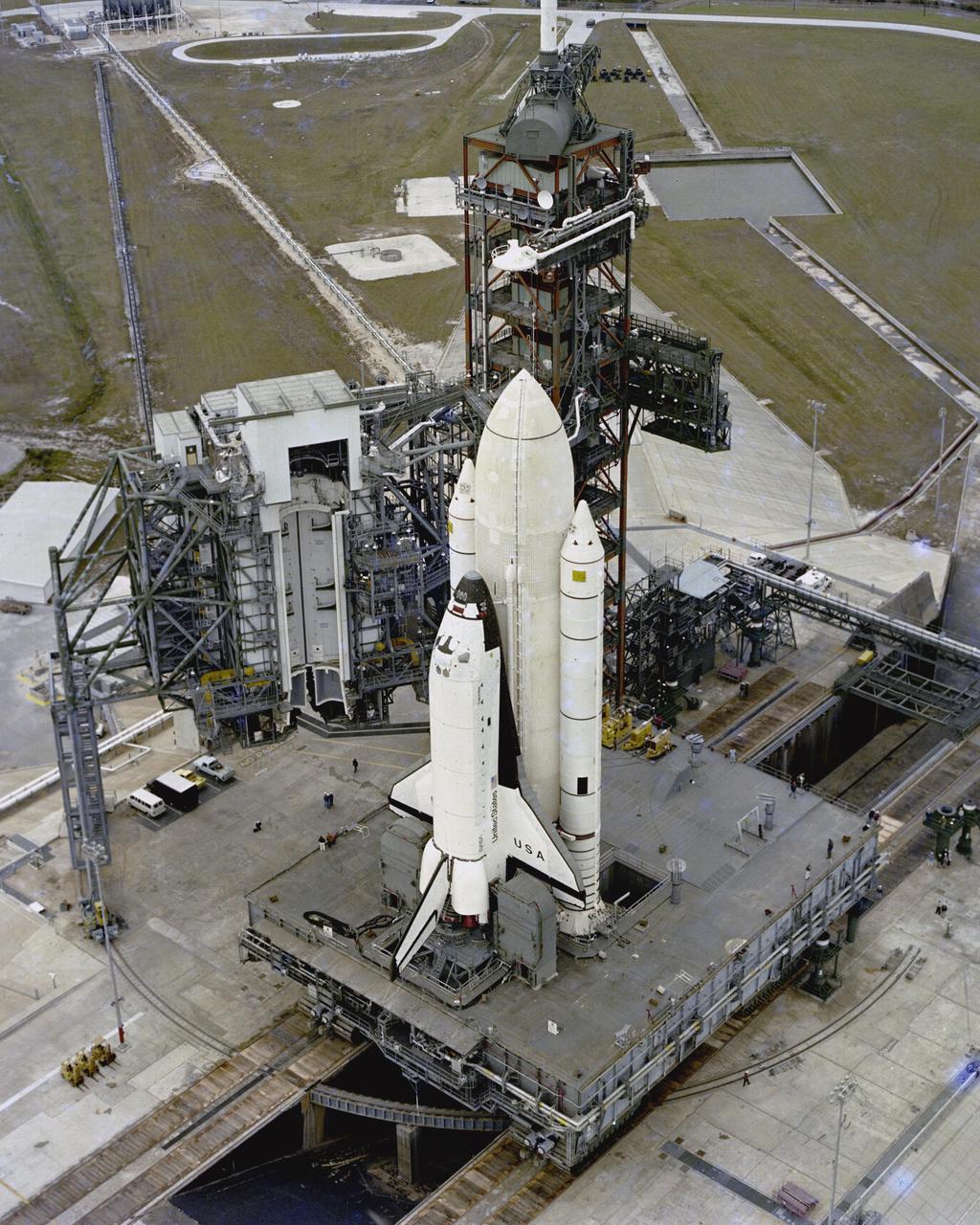
KENNEDY SPACE CENTER, FLA. - The first Space Shuttle vehicle destined to fly in space arrives at its launch site, Pad A at Complex 39, following a 3.5-mile move from the Vehicle Assembly Building where the vehicle was assembled. The rollout of the STS-1 vehicle - consisting of America's first reusable spaceship, Columbia, the external propellant tank and twin solid rocket boosters - from the VAB to the launch pad is a major milestone in the series of events that will lead to its scheduled liftoff in March 1981.
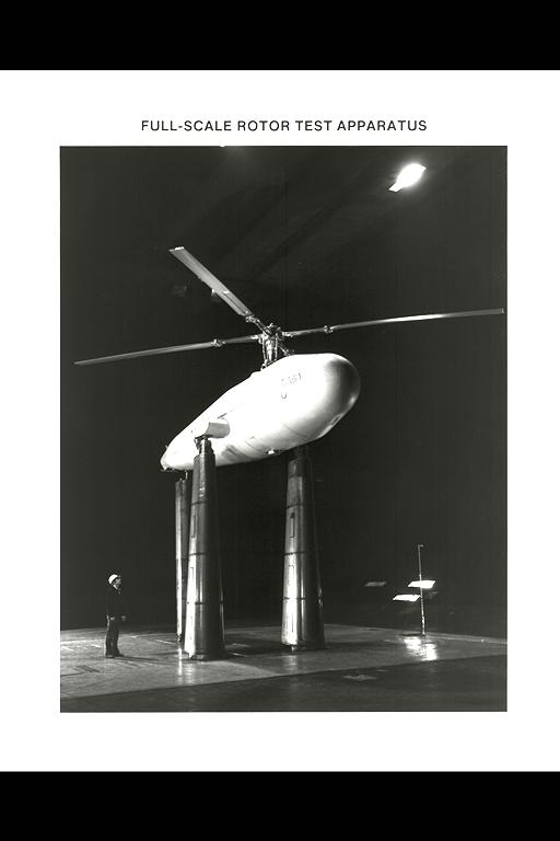
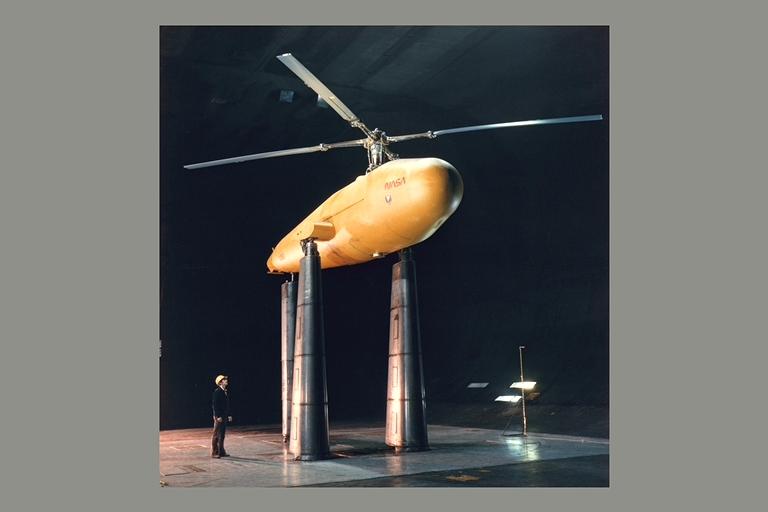
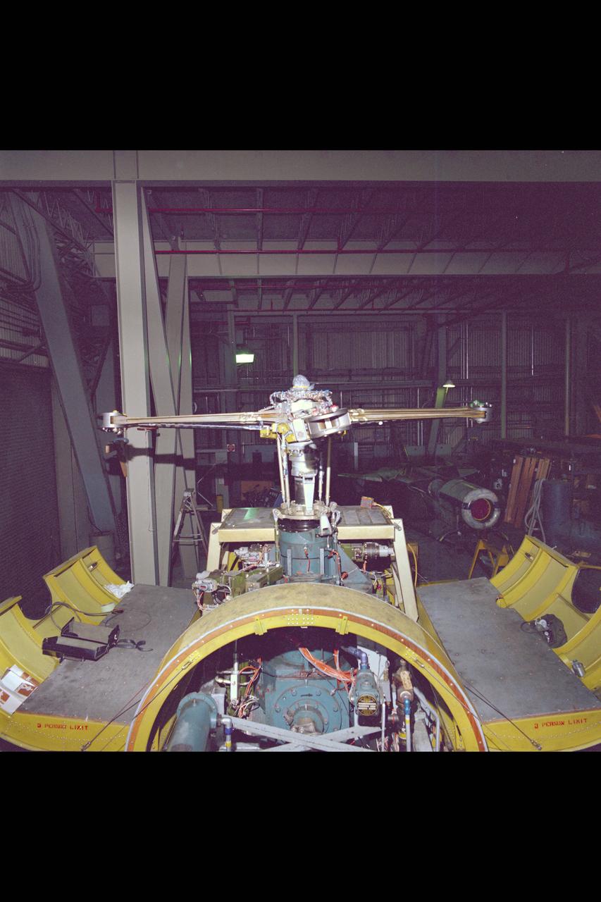
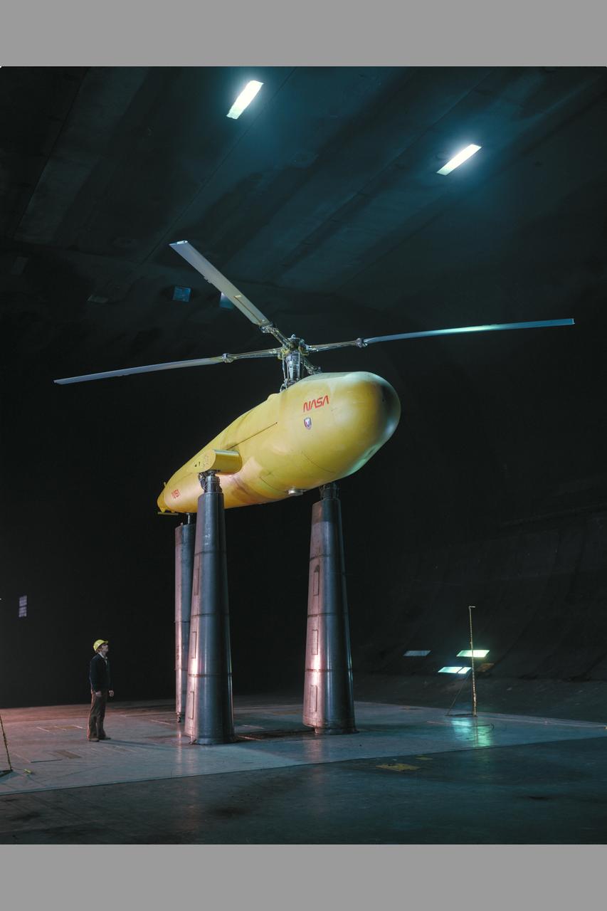
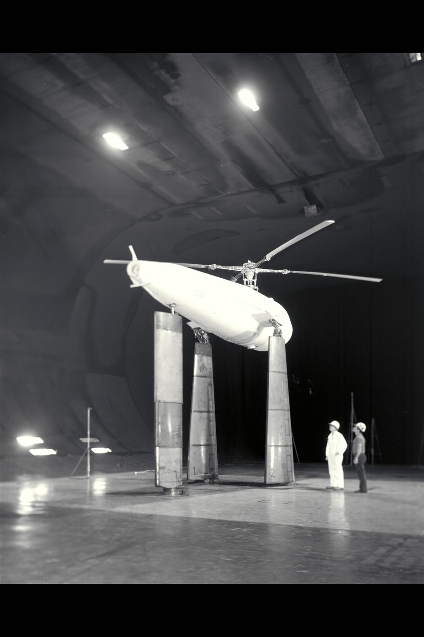
Sykorsky Bearingless Main Rotor test in 40x80ft w.t. (Full-Scale Rotor Test Apparatus)
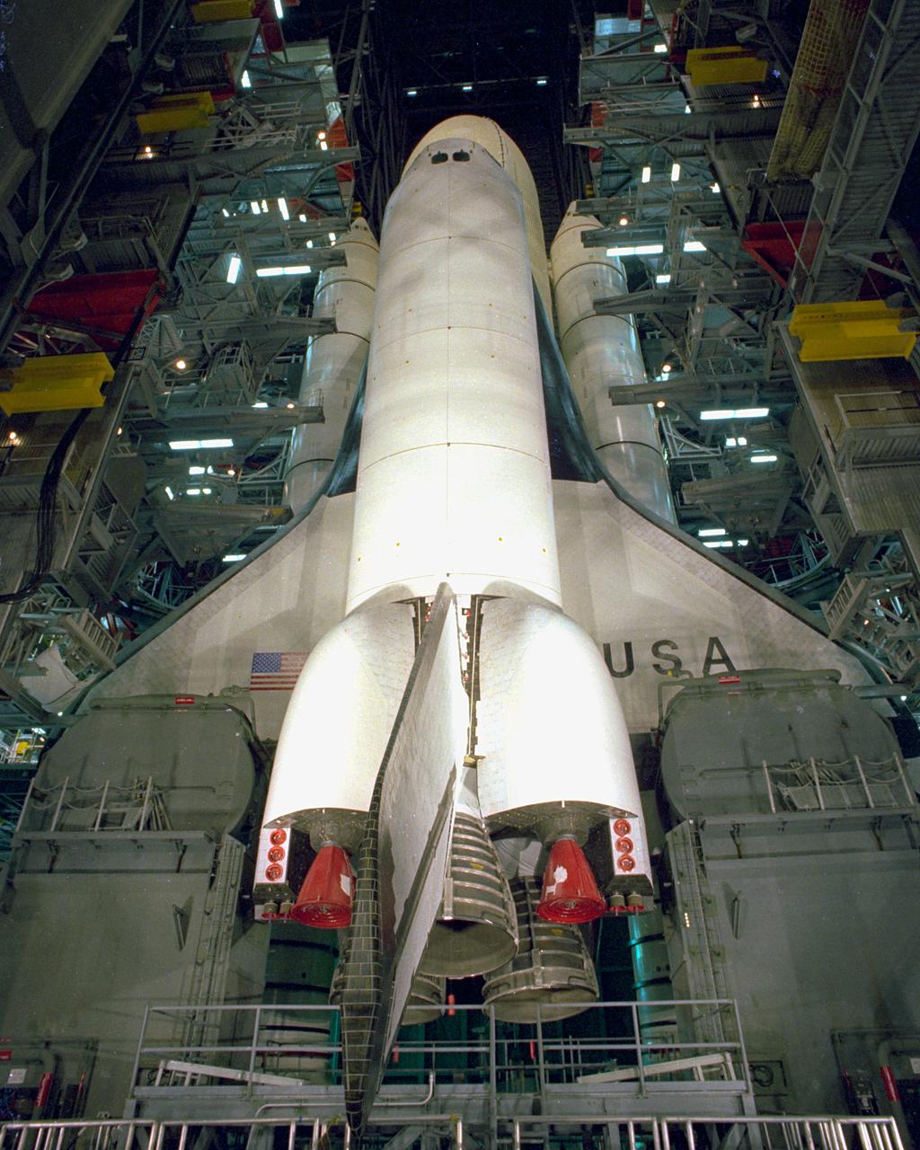
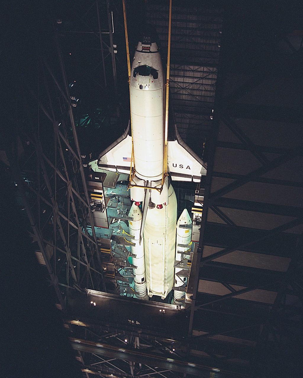
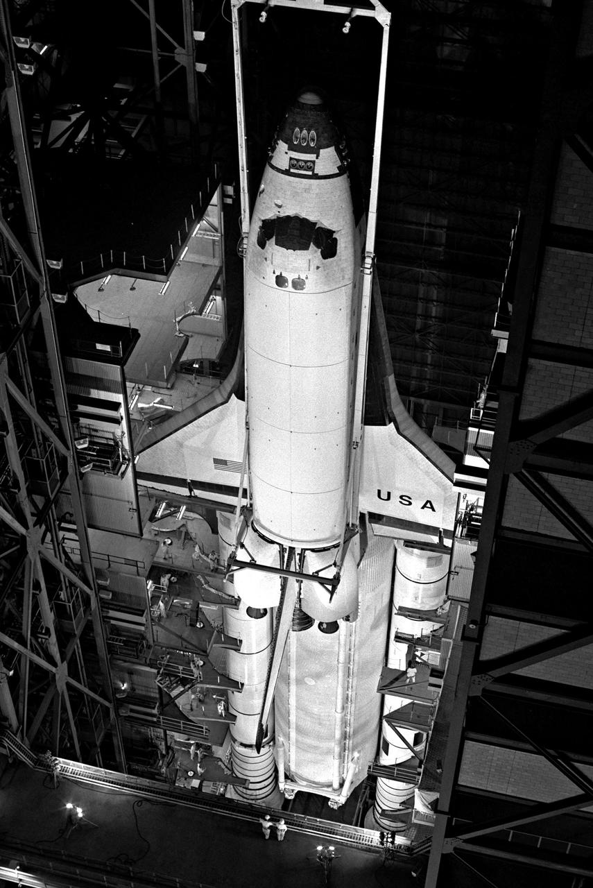
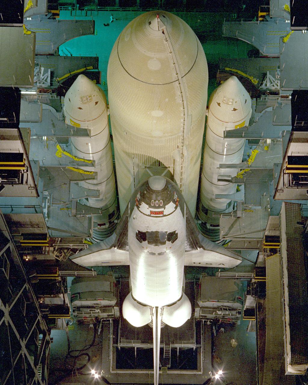
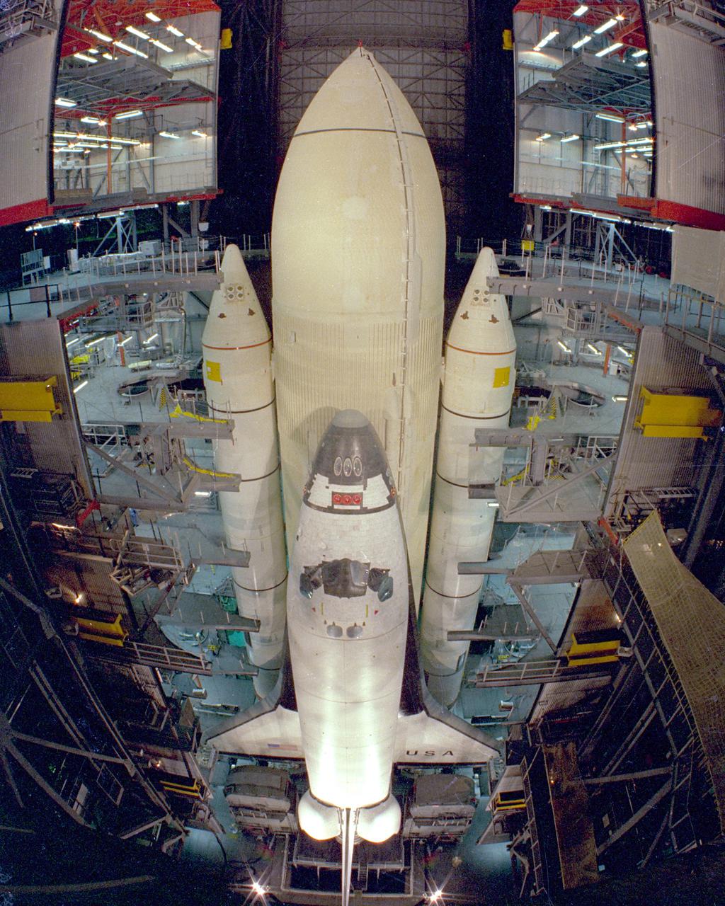
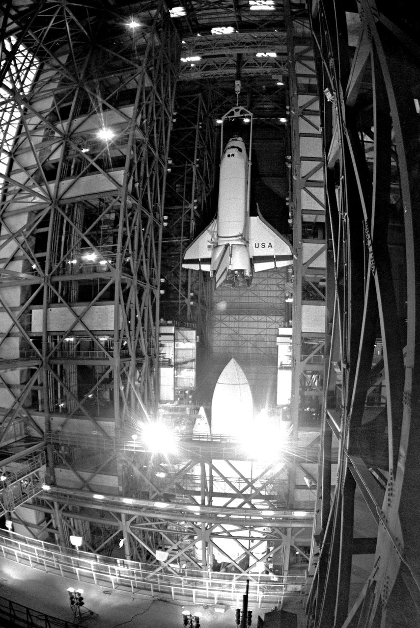
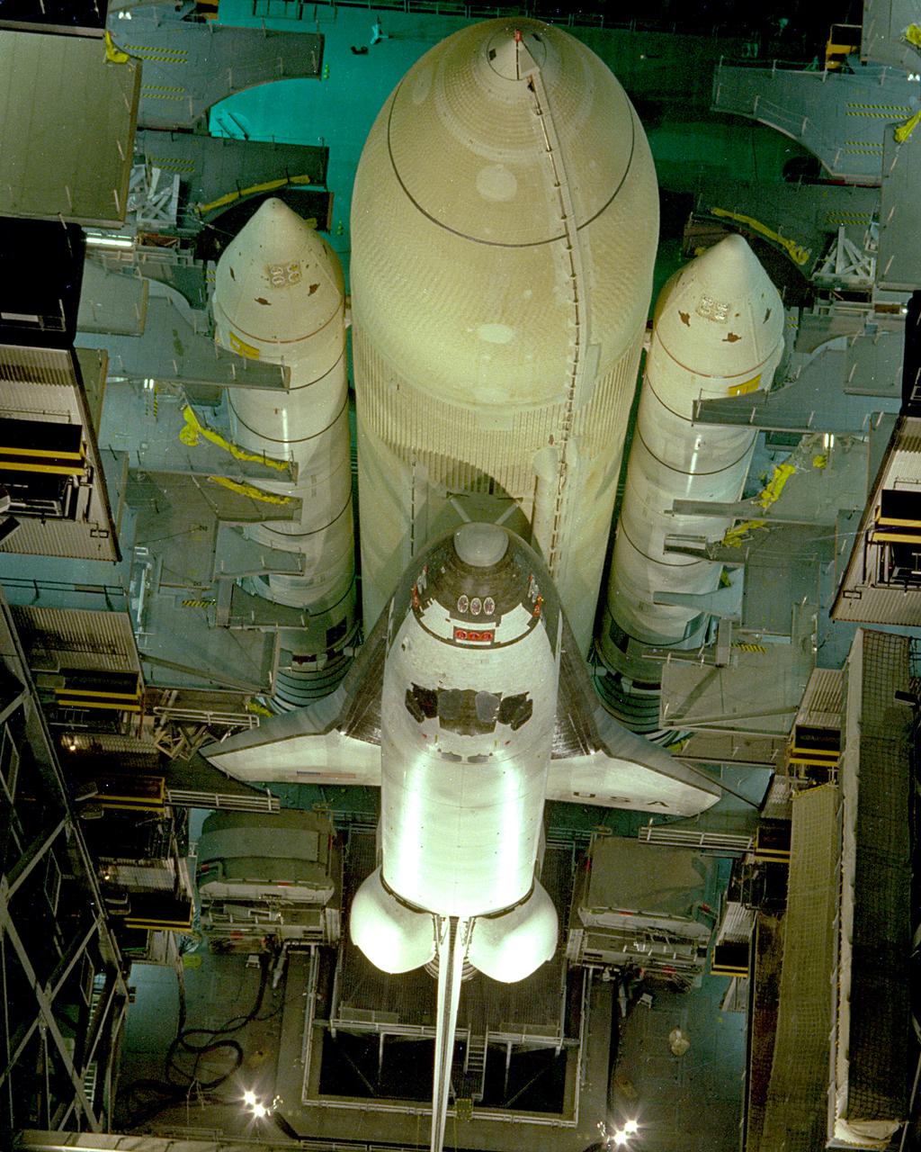
KENNEDY SPACE CENTER, FLA. - Assembly of the first Space Shuttle vehicle, scheduled to make its first orbital test flight in March 1981, was completed today with the mating of the Orbiter Columbia to its external tank in the Vehicle Assembly Building's High Bay 3. Columbia, shown here still attached to its hoisting sling, was moved to the VAB on Nov. 24 having completed tests and tile installation in the adjacent Orbiter Processing Facility. The other Shuttle components, the twin solid rocket boosters and the external propellant tank, were stacked on the Mobile Launcher Platform in High Bay 3 in January and November of this year, respectively. The current schedule calls for the rollout of the assembled Space Shuttle to Pad A at Launch Complex 39 shortly after Christmas.
C-141 KAO: CAT experiment - Damage Compressor
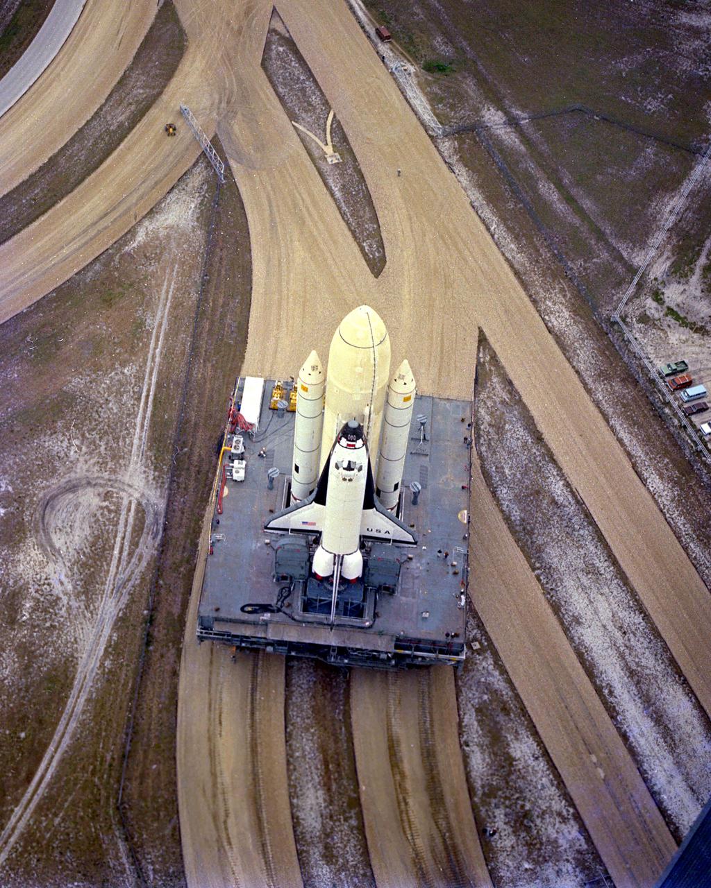
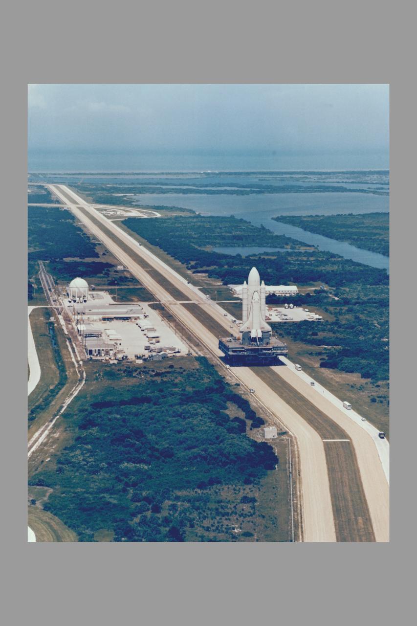
KENNEDY SPACE CENTER, FLA. - The first Space Shuttle vehicle destined to fly in space moves toward Pad A at Complex 39, where it will be launched. The STS-1 vehicle - consisting of America's first reusable spaceship, Columbia, the external propellant tank and twin solid rocket boosters - was assembled on a Mobile Launcher Platform in the Vehicle Assembly Building. A six-million-pound tractor, called the Crawler-Transporter, is used to carry the Space Shuttle from the VAB to the launch pad, about 3.5 miles away.
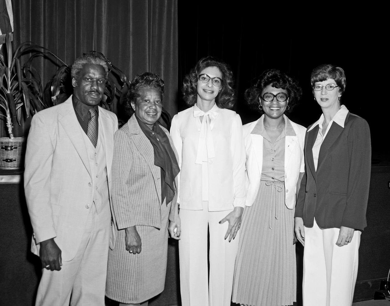
Federal Woman's Week, 1980 Various speakers, lecture groups, Mary Jackson in second from the left in this photo.
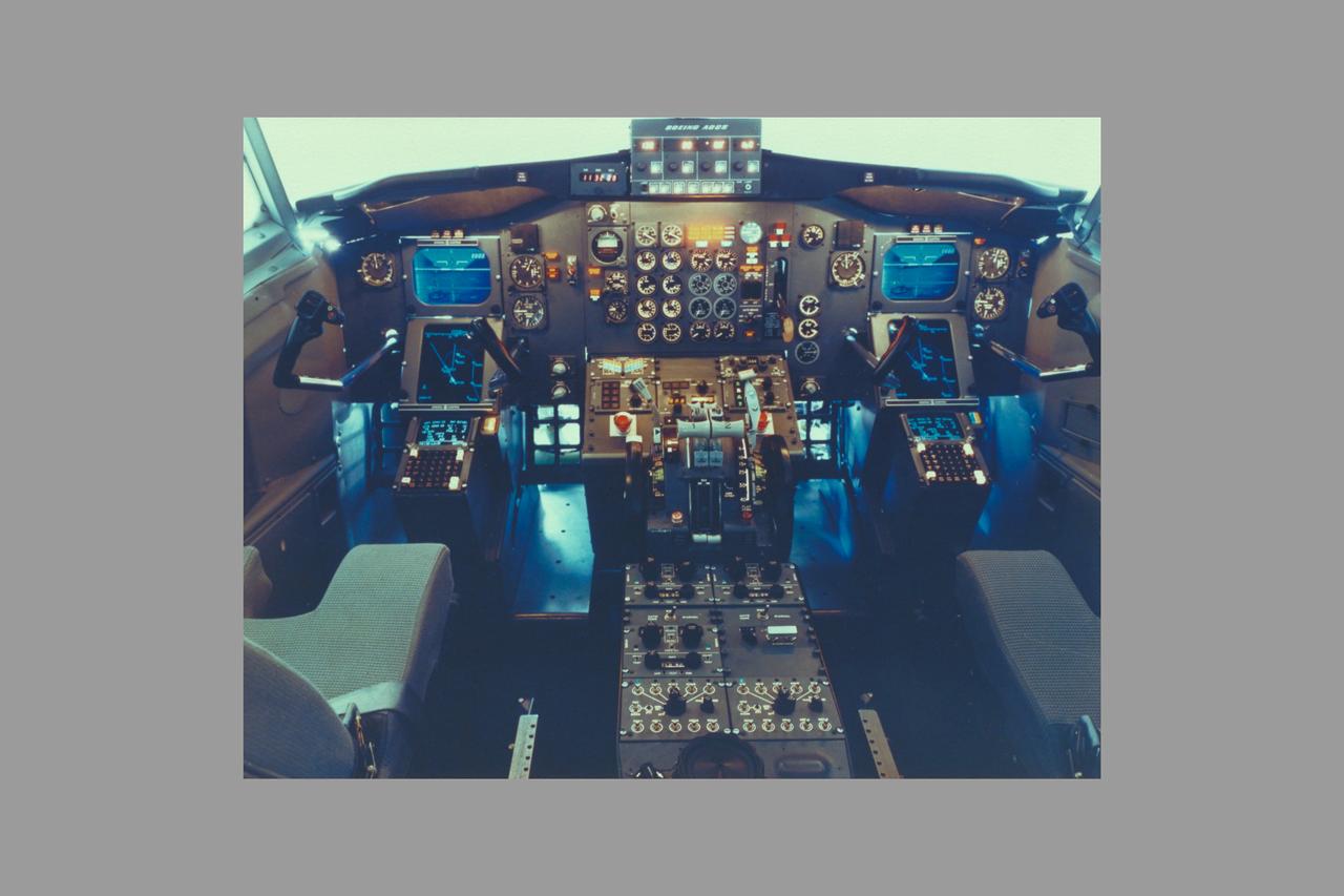
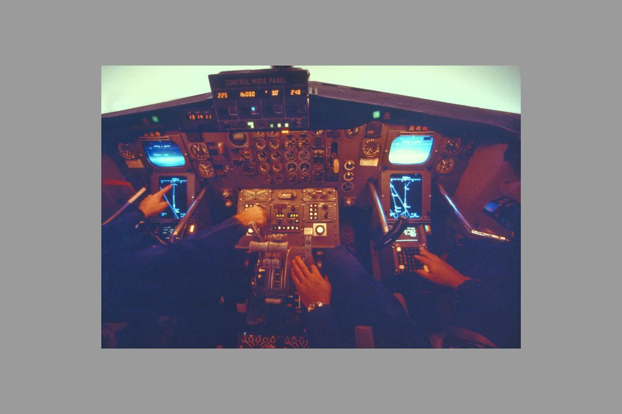
Boeing model 737 TCV research cockpit

C-141 KAO: CAT equipment
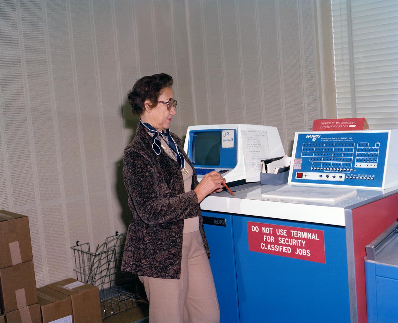
Mrs. Katherine G. Johnson at Work
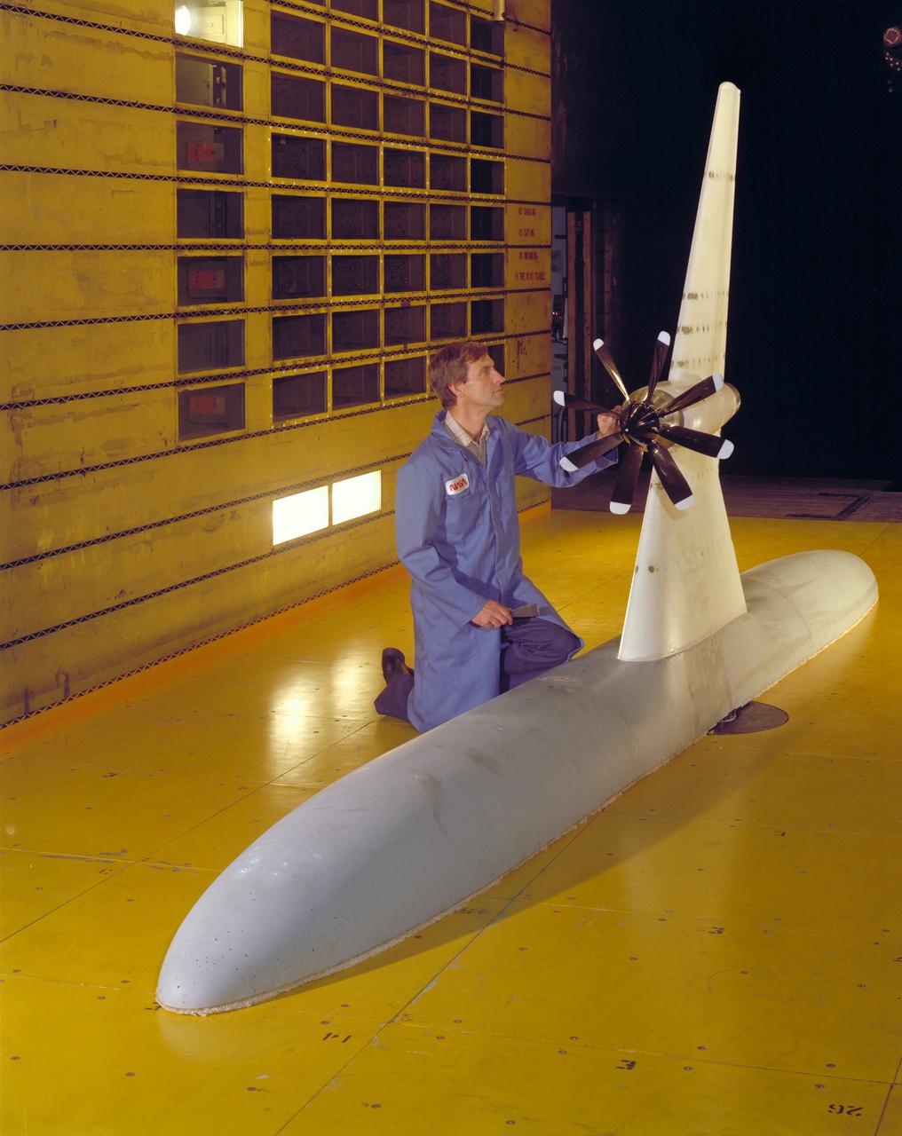
Turbo-prop semi-span model test-435 in 14ft w.t. with Ron Smith
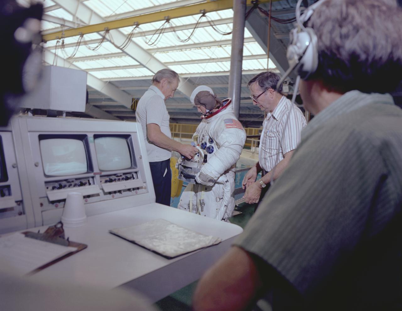
The Hubble Space Telescope (HST) is a cooperative program of the European Space Agency (ESA) and the National Aeronautical and Space Administration (NASA) to operate a long-lived space-based observatory. It was the flagship mission of NASA's Great Observatories program. The HST program began as an astronomical dream in the 1940s. During the 1970s and 1980s, the HST was finally designed and built becoming operational in the 1990s. The HST was deployed into a low-Earth orbit on April 25, 1990 from the cargo bay of the Space Shuttle Discovery (STS-31). The design of the HST took into consideration its length of service and the necessity of repairs and equipment replacement by making the body modular. In doing so, subsequent shuttle missions could recover the HST, replace faulty or obsolete parts and be re-released. MSFC's Neutral Buoyancy Simulator (NBS) served as the test center for shuttle astronauts training for Hubble related missions. Shown is astronaut Anna Fisher suiting up for training on a mockup of a modular section of the HST for an axial scientific instrument change out.
Once the United States' space program had progressed from Earth's orbit into outerspace, theprospect of building and maintaining a permanent presence in space was realized. To accomplish this feat, NASA launched a temporary workstation, Skylab, to discover the effects of low gravity and weightlessness on the human body, and also to develop tools and equipment that would be needed in the future to build and maintain a more permanent space station. The structures, techniques, and work schedules had to be carefully designed to fit this unique construction site. The components had to be lightweight for transport into orbit, yet durable. The station also had to be made with removable parts for easy servicing and repairs by astronauts. All of the tools necessary for service and repairs had to be designed for easy manipulation by a suited astronaut. Construction methods had to be efficient due to the limited time the astronauts could remain outside their controlled environment. In lieu of all the specific needs for this project, an environment on Earth had to be developed that could simulate a low gravity atmosphere. A Neutral Buoyancy Simulator (NBS) was constructed by NASA's Marshall Space Flight Center (MSFC) in 1968. Since then, NASA scientists have used this facility to understand how humans work best in low gravity and also provide information about the different kinds of structures that can be built. Pictured is a Massachusetts Institute of Technology (MIT) student working in a spacesuit on the Experimental Assembly of Structures in Extravehicular Activity (EASE) project which was developed as a joint effort between MFSC and MIT. The EASE experiment required that crew members assemble small components to form larger components, working from the payload bay of the space shuttle. The MIT student in this photo is assembling two six-beam tetrahedrons.
The payload bay doors of the Space Shuttle Orbiter Columbia were opened for the first time today using the orbiter's onboard door operation system. The hinges of the payload bay doors are not designed to support the weight of the doors while open horizontally in the Earth's one 'g' environment and a counterweight zero 'g' device supports the weight of the doors while they are open for processing in the OPF.

C-141 KAO: CAT Experiment

DAST cockpit
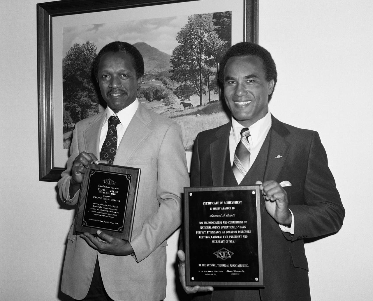
From left to right; Gilbert A. Haynes holding the NTA Fred C. Downs Special Event Award and Samuel J. Scott with award for their participation in the local Hampton Roads Chapter of the (NTA) National Technical Association. The guidance and counseling of minority youth is one of NTA's prime objectives. Formed in 1925, NTA has 15 chapters comprised of architects,engineers, scientists, and educators. NTA activities are directed toward encouraging and assisting public and private institutions in identifying potential minority technical talent.
The Hubble Space Telescope (HST) is a cooperative program of the European Space Agency (ESA) and the National Aeronautical and Space Administration (NASA) to operate a long-lived space-based observatory. It was the flagship mission of NASA's Great Observatories program. The HST program began as an astronomical dream in the 1940s. During the 1970s and 1980s, the HST was finally designed and built becoming operational in the 1990s. The HST was deployed into a low-Earth orbit on April 25, 1990 from the cargo bay of the Space Shuttle Discovery (STS-31). The design of the HST took into consideration its length of service and the necessity of repairs and equipment replacement by making the body modular. In doing so, subsequent shuttle missions could recover the HST, replace faulty or obsolete parts and be re-released. Marshall SPace Flight Center’s (MSFC's) Neutral Buoyancy Simulator (NBS) served as the test center for shuttle astronauts training for Hubble related missions. Shown is astronaut Anna Fisher suited up for training on a mockup of a modular section of the HST for an axial scientific instrument change out.
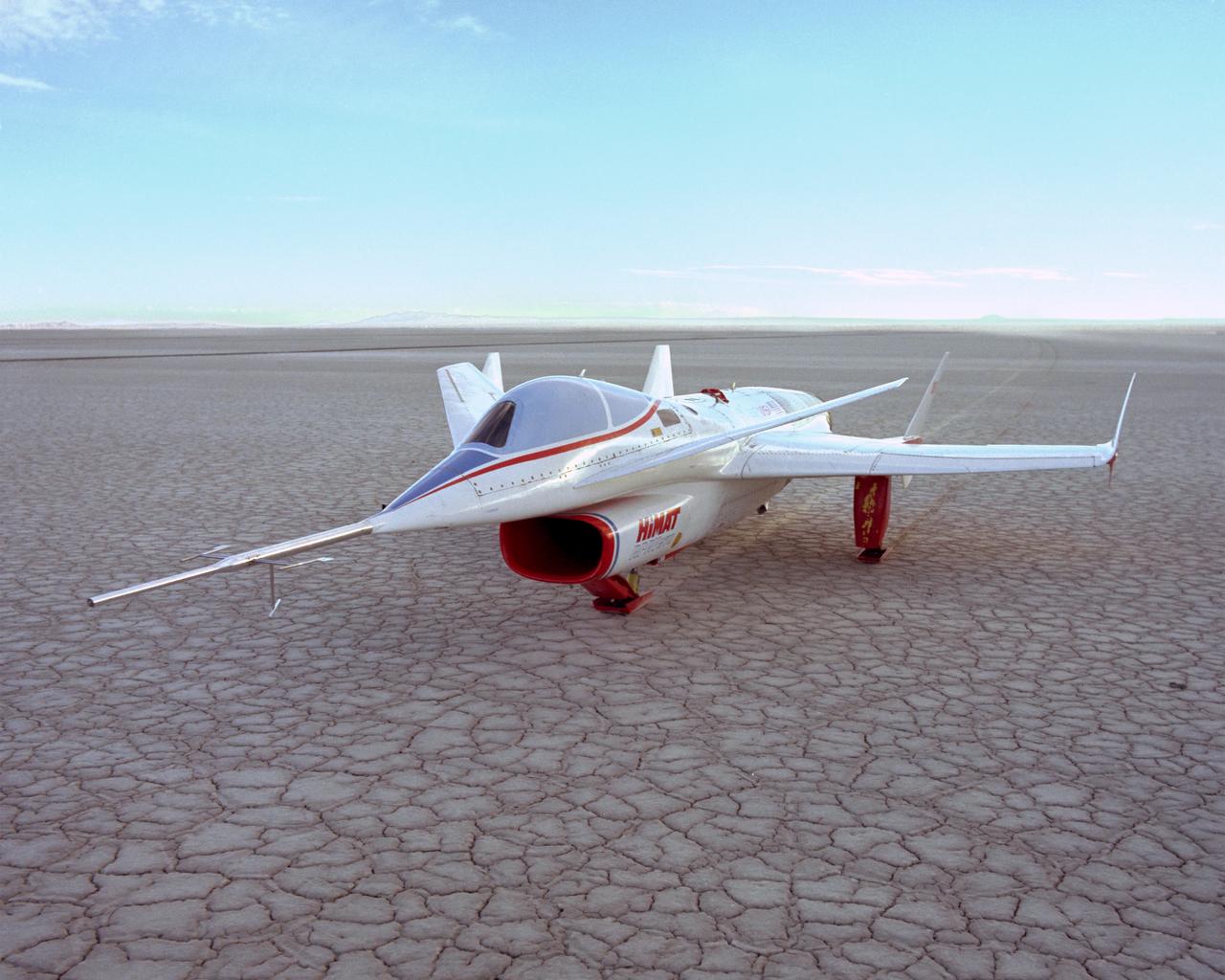
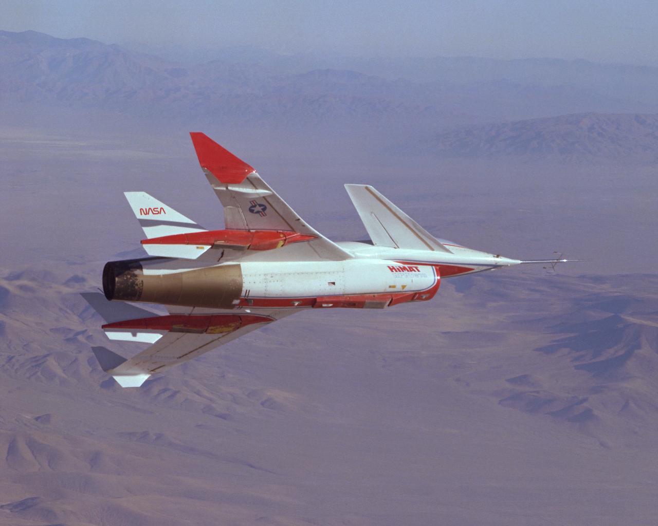
The HiMAT (Highly Maneuverable Aircraft Technology) subscale research vehicle, seen here after landing to conclude a research flight, was flown by the NASA Dryden Flight Research Center, Edwards, California, from mid 1979 to January 1983. The aircraft demonstrated advanced fighter technologies that have been used in the development of many modern high performance military aircraft.
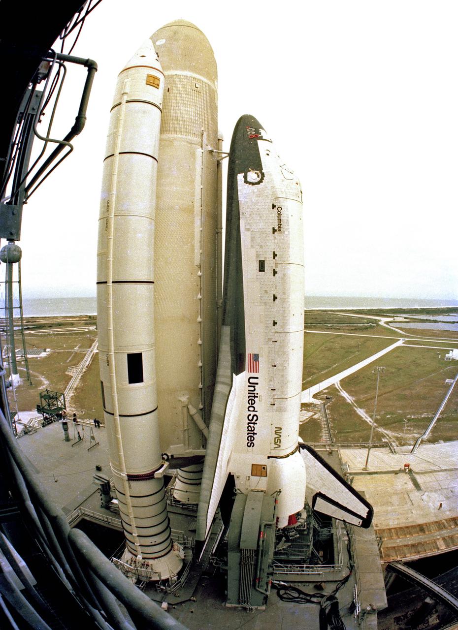
CAPE CANAVERAL, Fla. – STS-1, orbiter Columbia, sits at Launch Complex 39A after being rolled out of the VAB. Photo credit: NASA
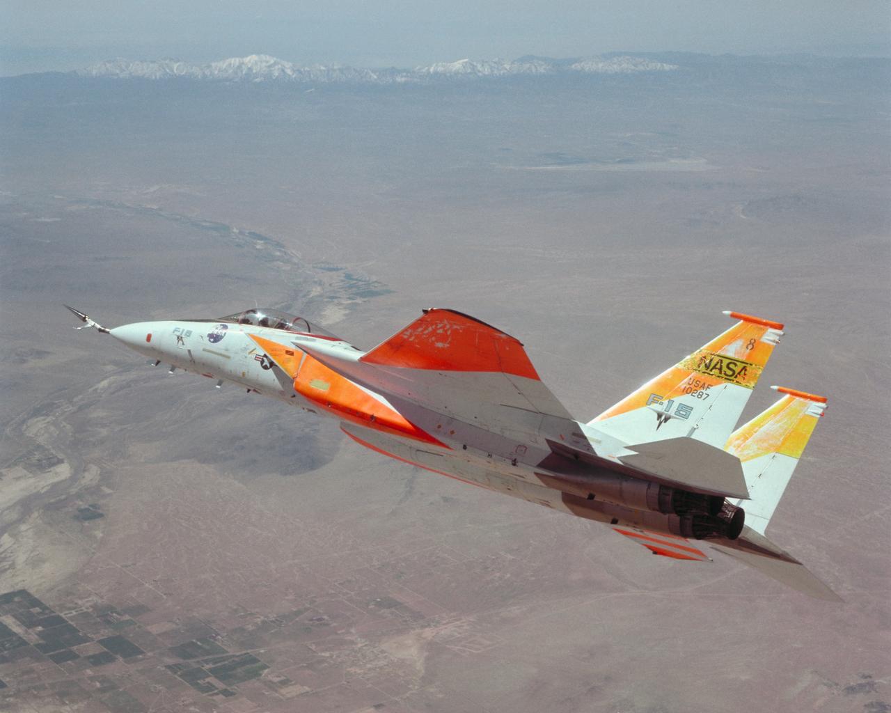
An in-flight photo of the NASA F-15A with a 10 degree cone to collect aerodynamic information to calibrate data from wind tunnels.
Boeing model 747 flight deck (photo courtesy: National Geographic)
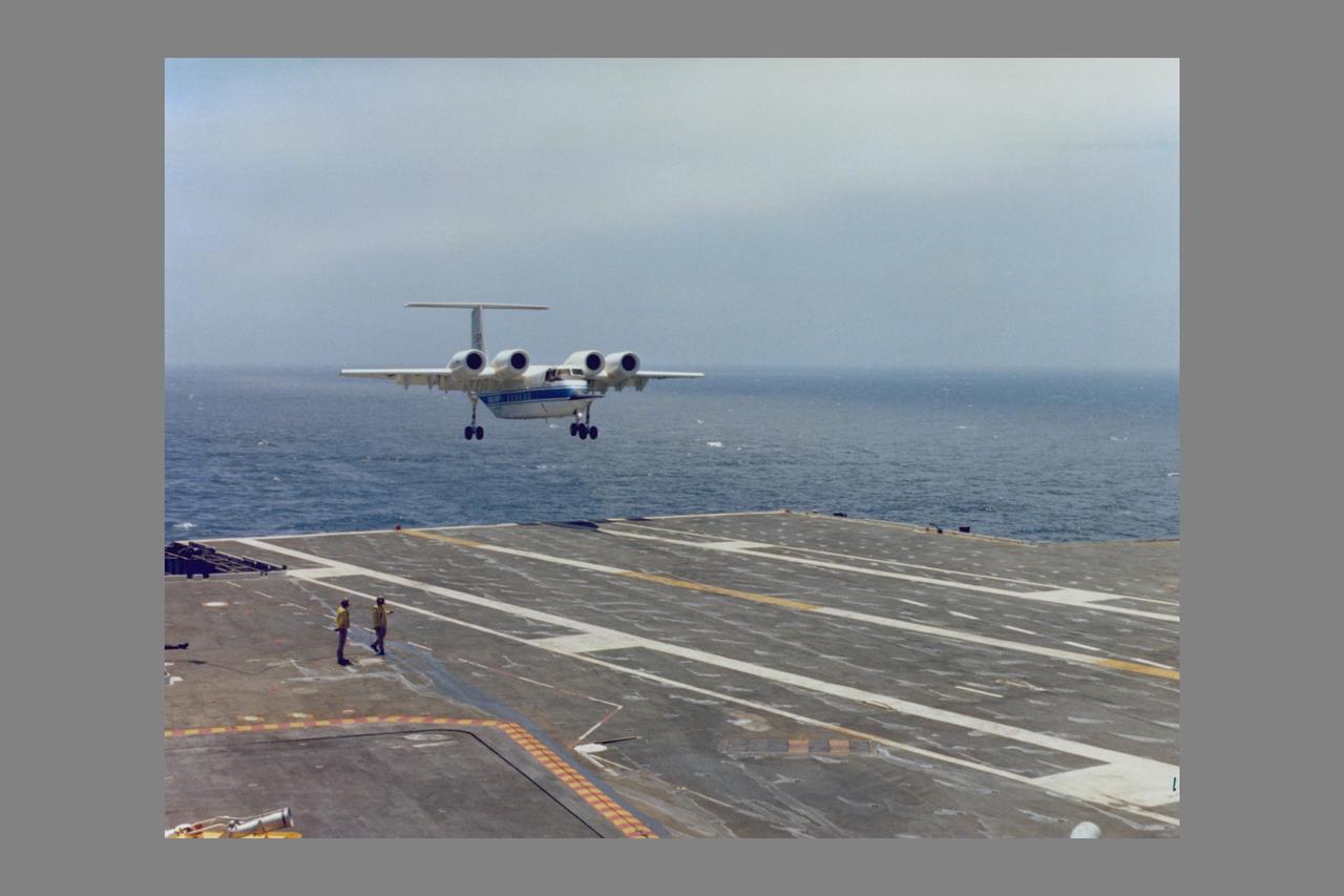
QSRA (NASA-715) takeoff and landing trials onboard the USS Kitty Hawk
KENNEDY SPACE CENTER, FLA. - Shuttle Orbiter Columbia move from OPF and mate to external tank in VAB.
Sikorsky Bearingless Main Rotor test in 40x80ft w.t.
KENNEDY SPACE CENTER, FLA. - The first Space Shuttle vehicle destined to fly in space moves toward Launch Complex 39A where it will be launched. The STS-1 vehicle, consisting of America’s first reusable space ship - the orbiter Columbia, an external propellant tank and two solid rocket boosters, was assembled on a Mobile Launcher Platform in the Vehicle Assembly Building. A six-million pound tractor, called the Crawler-Transporter, is used to carry the Space Shuttle from the VAB to the launch pad, some 3.5 miles away.
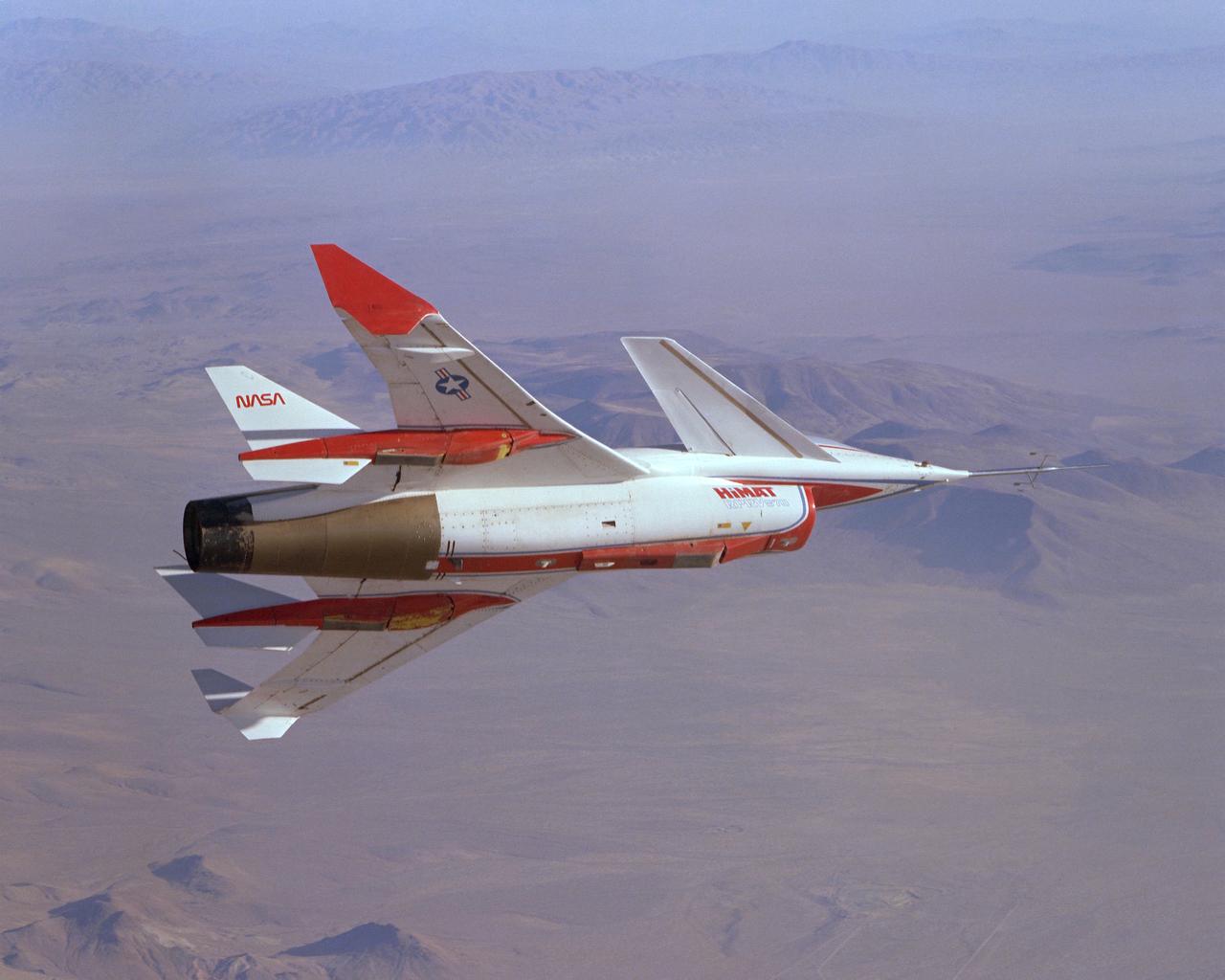
The HiMAT (Highly Maneuverable Aircraft Technology) subscale research vehicle, seen here during a research flight, was flown by the NASA Dryden Flight Research Center, Edwards, California, from mid 1979 to January 1983. The aircraft demonstrated advanced fighter technologies that have been used in the development of many modern high performance military aircraft.
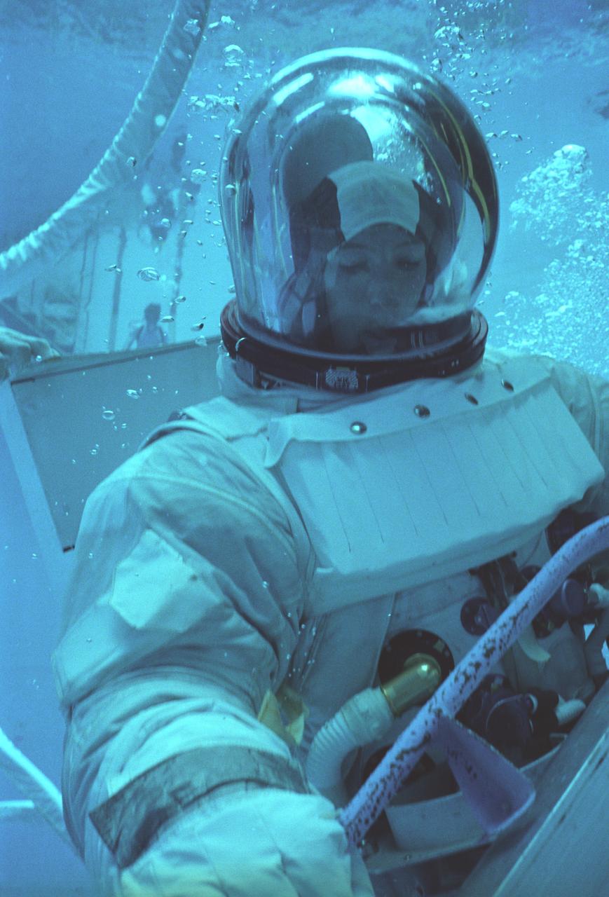
The Hubble Space Telescope (HST) is a cooperative program of the European Space Agency (ESA) and the National Aeronautical and Space Administration (NASA) to operate a long-lived space-based observatory. It was the flagship mission of NASA's Great Observatories program. The HST program began as an astronomical dream in the 1940s. During the 1970s and 1980s, the HST was finally designed and built becoming operational in the 1990s. The HST was deployed into a low-Earth orbit on April 25, 1990 from the cargo bay of the Space Shuttle Discovery (STS-31). The design of the HST took into consideration its length of service and the necessity of repairs and equipment replacement by making the body modular. In doing so, subsequent shuttle missions could recover the HST, replace faulty or obsolete parts and be re-released. Marshall Space Flight Center’s (MSFC's) Neutral Buoyancy Simulator (NBS) served as the test center for shuttle astronauts training for Hubble related missions. Shown is astronaut Anna Fisher training on a mock-up of a modular section of the HST for an axial scientific instrument change out.
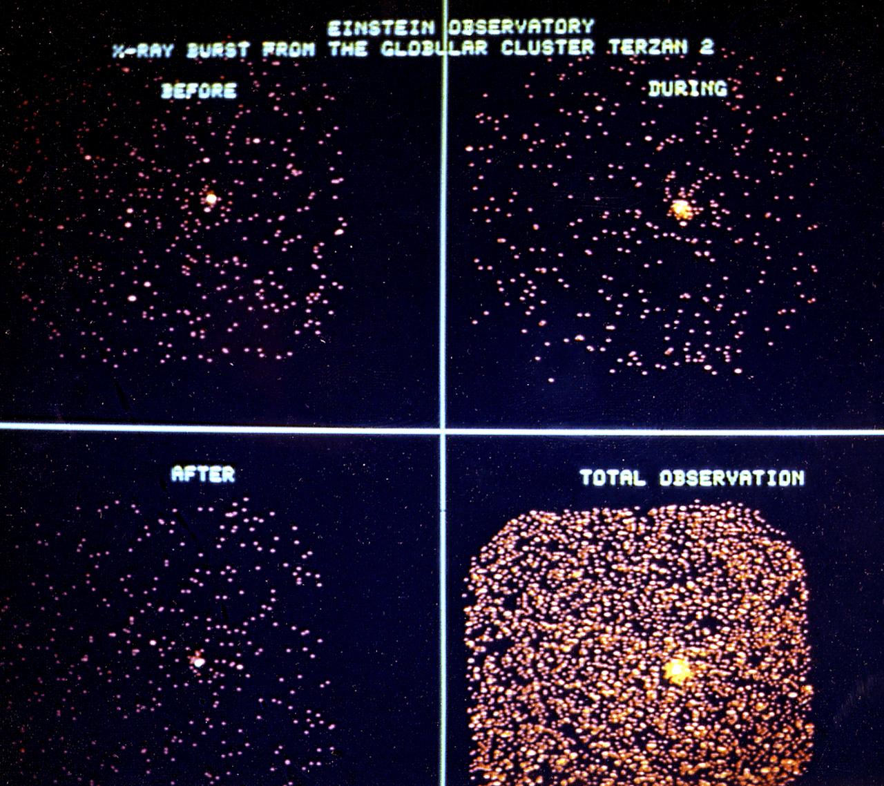
The dramatic change in x-ray emission from the Terzan 2 cluster is shown in this series of 2.5-minute exposures taken with the High Energy Astronomy Observatory (HEAO)-2/Einstein Observatory immediately before, during, and after the burst. Total exposure (20 minutes) of the object, including the outburst, is shown in the fourth photograph. These images represent the first observation of an x-ray burst in progress. The actual burst lasted 50 seconds. Among the rarest, and most bizarre, phenomena observed by x-ray astronomers are the so-called cosmic bursters (x-ray sources that suddenly and dramatically increase in intensity then subside). These sudden bursts of intense x-ray radiation apparently come from compact objects with a diameter smaller than 30 miles (48 kilometers). Yet, despite their minuscule size, a typical x-ray burster can release more x-ray energy in a single brief burst than our Sun does in an entire week. The HEAO-2, the first imaging and largest x-ray telescope built to date, was capable of producing actual photographs of x-ray objects. Shortly after launch, the HEAO-2 was nicknamed the Einstein Observatory by its scientific experimenters in honor of the centernial of the birth of Albert Einstein, whose concepts of relativity and gravitation have influenced much of modern astrophysics, particularly x-ray astronomy. The HEAO was designed and developed by TRW, Inc. under the project management of the Marshall Space Flight Center.
KENNEDY SPACE CENTER, FLA. - Shuttle Orbiter Columbia erection and mate in the Vehicle Assembly Building (VAB).
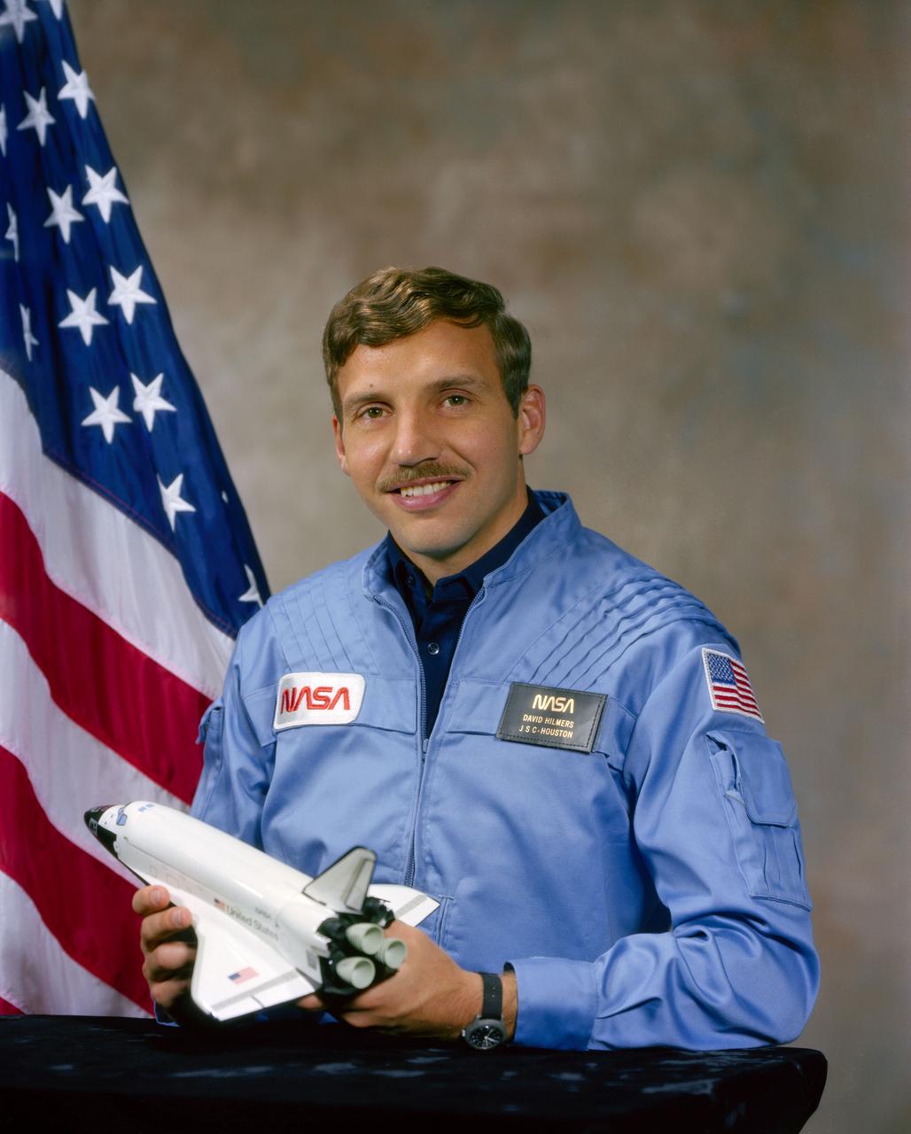
S80-42909 (December 1980) --- Astronaut David C. Hilmers
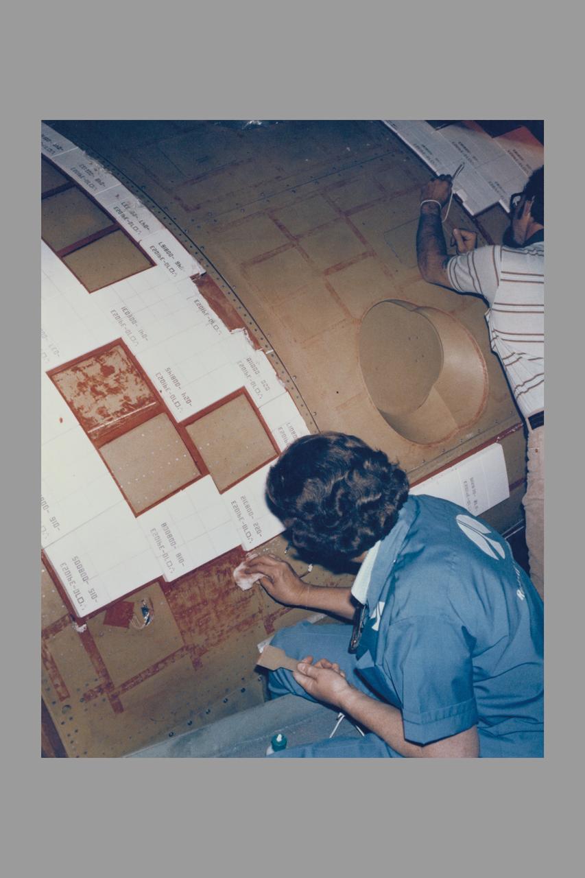
ROCKWELL INTERNATIONAL TECHNICIANS MOUNT SOME OF THE NEARLY 8,000 CERAMIC-COATED TILES THAT REMAIN TO BE INSTALLED ON THE EXTERNAL SURFACES OF THE SPACE SHUTTLE ORBITER COLUMBIA TO COMPLETE THE THERMAL PROTECTION SYSTEM THAT WILL ABSORB THE INTENSE HEAT OF REENTERING THE EARTH'S ATMOSPHERE AFTER A MISSION IN SPACE. TILE INSTALLATION IS DONE ON AN AROUND-THE-CLOCK BASIS IN THE ORBITER PROCESSING FACILITY WHERE COLUMBIA, THE FIRST IN A NEW BREED OF MANNED, REUSABLE SPACECRAFT, IS BEING READIED FOR THE FIRST LAUNCH OF THE SPACE SHUTTLE LATER THIS YEAR.
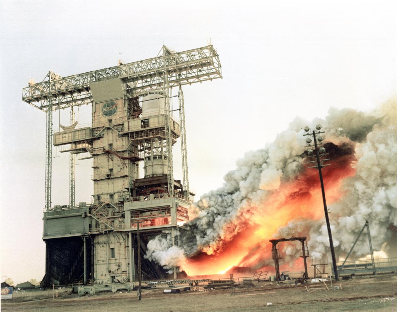
Pictured is a dual position Saturn I/IB test at the T-Stand at Marshall Space Flight Center. This stand was built to test two articles at the same time, thus providing engineers at MSFC with the opportunity to compare identical burns.

S80-38456 (13 Aug 1980) --- Claude Nicollier of Switzerland, one of two European scientists/Spacelab payload specialist candidates training in the United States along with 19 new NASA astronaut candidates, grabs onto the one-man life raft he is using during a water survival training school attended by several JSC personnel in mid-August. Six of the 19 candidates who had not had this type training before and the two Europeans were joined by a veteran astronaut, training personnel and two NASA physicians on the trip.
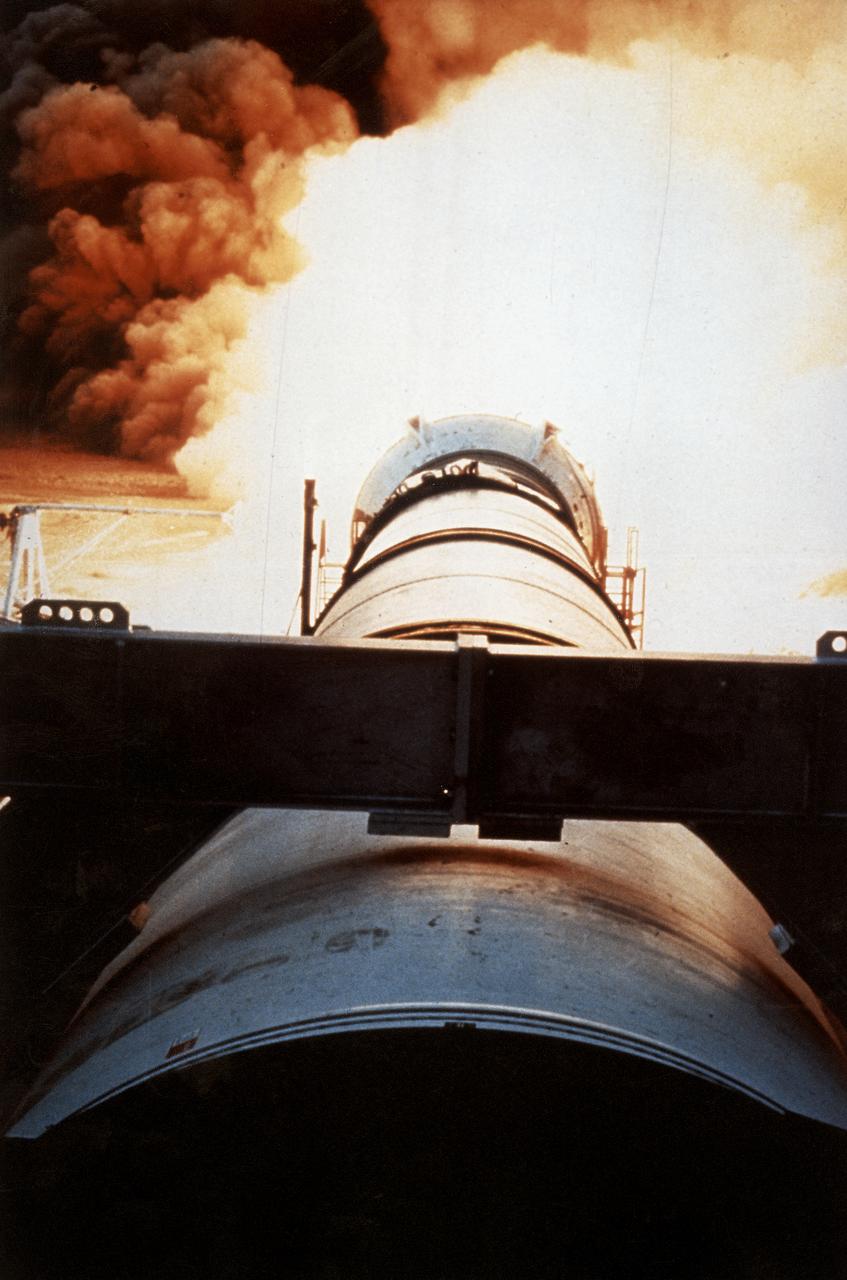
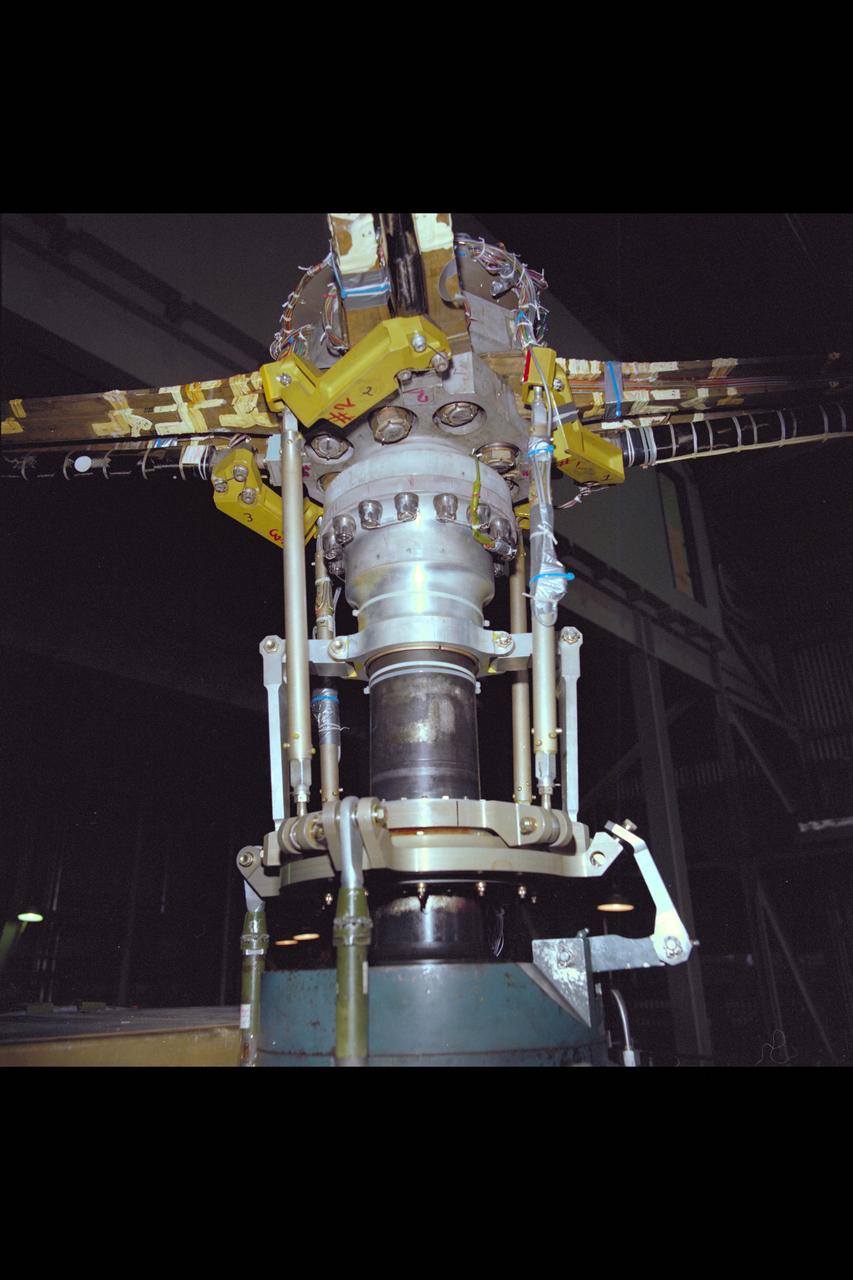
One of the key tests in the effort to return the Space Shuttle to flight following the Challenger accident was testing the development Motor-8 (DM-8). The 126-foot long, 1.2-million-pound motor, designated DM-8, underwent a full-duration horizontal test firing for two minutes at the Thiokol test facility in Utah. It was fitted with more than 500 instruments to measure such things as acceleration, pressure, deflection thrust, strain, temperature, and electrical properties.
KENNEDY SPACE CENTER, FLA. - Assembly of the first Space Shuttle vehicle, scheduled to make its first orbital test flight in March 1981, was completed today with the mating of the Orbiter Columbia to its external tank in the Vehicle Assembly Building's High Bay 3. Columbia, shown here still attached to its hoisting sling, was moved to the VAB on Nov. 24 having completed tests and tile installation in the adjacent Orbiter Processing Facility. The other Shuttle components, the twin solid rocket boosters and the external propellant tank, were stacked on the Mobile Launcher Platform in High Bay 3 in January and November of this year, respectively. The current schedule calls for the rollout of the assembled Space Shuttle to Pad A at Launch Complex 39 shortly after Christmas.
Bearingless Main Rotor
C-141 KAO: CAT experiement
S80-36889 (24 July 1980) --- Astronaut Bruce McCandless II uses a simulator at Martin Marietta?s space center near Denver to develop flight techniques for a backpack propulsion unit that will be used on Space Shuttle flights. The manned maneuvering unit (MMU) training simulator allows astronauts to "fly missions" against a full scale mockup of a portion of the orbiter vehicle. Controls of the simulator are like those of the actual MMU. Manipulating them allows the astronaut to move in three straight-line directions and in pitch, yaw and roll. One possible application of the MMU is for an extravehicular activity chore to repair damaged tiles on the vehicle. McCandless is wearing an extravehicular mobility unit (EMU).
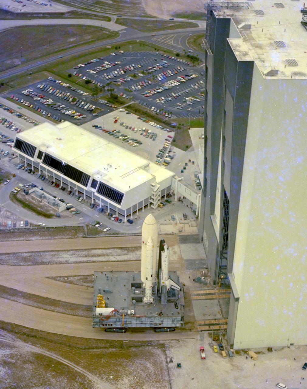
KENNEDY SPACE CENTER, FLA. - This aerial view of STS-1 shows the space vehicle for the first Space Shuttle mission shortly after it was moved out of the Vehicle Assembly Builidng's High Bay 3 for the 3.5-mile journey to Pad A at Launch Complex 39. In the center background is the Launch Control Center from which countdowns for Space Shuttle missions will be conducted. The rollout to the pad took place little more than a month after the Space Shuttle Orbiter Columbia was rolled from the Orbiter Processing Facility to the VAB for mating on a Mobile Launcher Platform with the STS-1 external tank and solid rocket boosters.
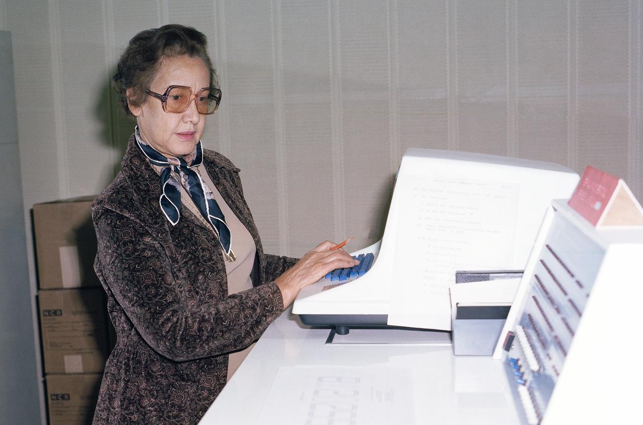
Mrs. Katherine G. Johnson at Work
Bearingless Main Rotor
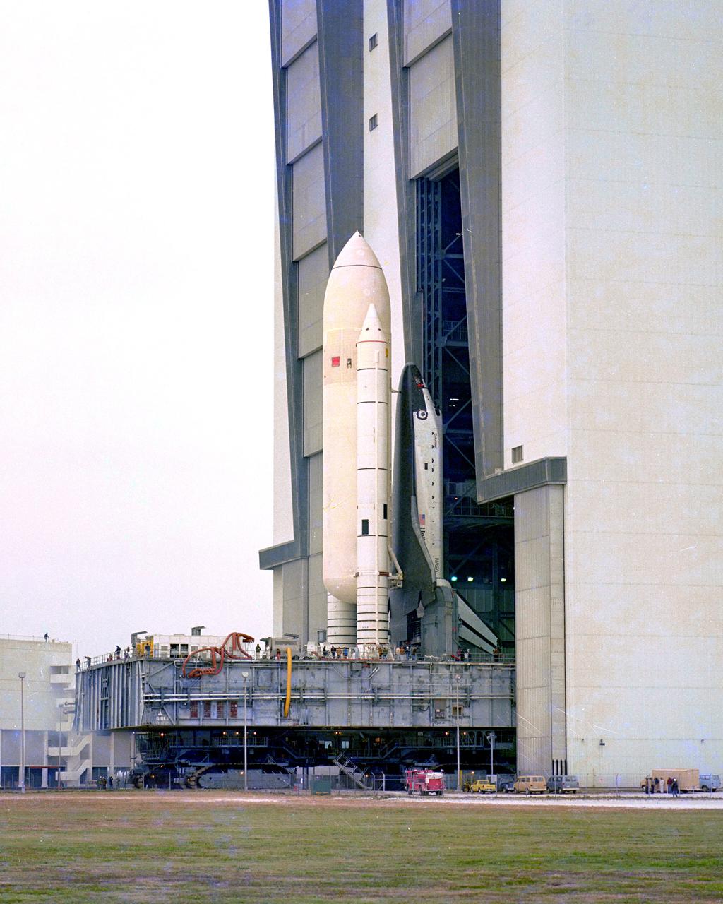
Space Shuttle Orbiter Enterprise, mated to a 15-story-tall external propellant tank and twin inert solid rocket boosters on top of a Mobile Launcher Platform, is rolled back to the Vehicle Assembly Building from Lauch Complex 39's Pad A July 23 at the completion of nearly three months of fit and function checks at the shuttle launch site as part of the exercise designed to help clear the way for the liftoff of its sister ship Columbia. The massive Crawler Transporter began moving its 11 million pound load the 3.5 miles from pad A to the VAB at 10:23 a.m. and reached the doorway to High Bay 1 at 3:48p.m. following serveral days of fit checks of modified extermiable platforms in the assembly bay, the nonlaunchable shuttle will be destacked. Enterprise will be returned to Rockwell International and stripped of parts for integration into orbiter destined for space, while the external tank and solid booster will be returned to their respective prime contractors and refurbished for use on a later shuttle mission.
Shuttle related interaction with the space telescope.
KENNEDY SPACE CENTER, FLA. - Assembly of the first Space Shuttle vehicle, scheduled to make its first orbital test flight in March 1981, was completed today with the mating of the Orbiter Columbia to its eternal tank in the Vehicle Assembly Building's High Bay 3. Columbia, shown here still attached to its hoisting sling, was moved to the VAB on Nov. 24 having completed tests and tile installation in the adjacent Orbiter Processing Facility. The other Shuttle components, the twin solid rocket boosters and the external propellant tank, were stacked on the Mobile launcher Platform in High Bay 3 in January and November of this year, respectively. The current schedule calls for the rollout of the assembled Space Shuttle to Pad A at Launch Complex 39 shortly after Christmas.
Sikorsky Bearingless Main Rotor test in 40x80ft w.t.
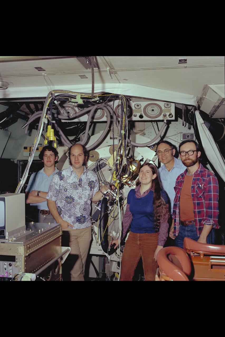
C-141 KAO: Dr Fred Witteborn and Ames Science Team onbaord for CAT experiment
The payload bay doors of the Space Shuttle Orbiter Columbia were opened for the first time today using the orbiter's onboard door operation system. The hinges of the payload bay doors are not designed to support the weight of the doors while open horizontally in the Earth's one 'g' environment and a counterweight zero 'g' device supports the weight of the doors while they are open for processing in the OPF.
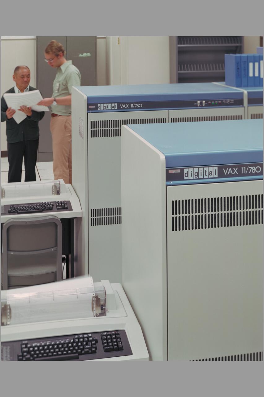
N-233 computer hardware - digital VAX-11/780
The HiMAT (Highly Maneuverable Aircraft Technology) subscale research vehicle, seen here during a research flight, was flown by the NASA Dryden Flight Research Center, Edwards, California, from mid 1979 to January 1983. The aircraft demonstrated advanced fighter technologies that have been used in the development of many modern high performance military aircraft.
SPACE SHUTTLE ORBITER ENTERPRISE STANDS ON KSC'S PAD 39A HIGHLIGHTED AGAINST THE DARKENED FLORIDA SKY DURING TESTING OF THE HIGH-INTENSITY LIGHTING SYSTMES. THE BANKS OF XENON LIGHTS ARE USED DURING LAUCH PREPARATIONS.
Sikorsky Bearingless Main Rotor test in 40x80ft w.t.
S80-36848 (24 July 1980) --- Photo of the Manned Maneuvering Unit (MMU) simulator at the Martin Marietta plant in Denver, Colorado. View of simulator with test subject strapped in to it.

This x-ray photograph of the Supernova remnant Cassiopeia A, taken with the High Energy Astronomy Observatory (HEAO) 2/Einstein Observatory, shows that the regions with fast moving knots of material in the expanding shell are bright and clear. A faint x-ray halo, just outside the bright shell, is interpreted as a shock wave moving ahead of the expanding debris. The HEAO-2, the first imaging and largest x-ray telescope built to date, was capable of producing actual photographs of x-ray objects. Shortly after launch, the HEAO-2 was nicknamed the Einstein Observatory by its scientific experimenters in honor of the centernial of the birth of Albert Einstein, whose concepts of relativity and gravitation have influenced much of modern astrophysics, particularly x-ray astronomy. The HEAO-2, designed and developed by TRW, Inc. under the project management of the Marshall Space Flight Center, was launched aboard an Atlas/Centaur launch vehicle on November 13, 1978.
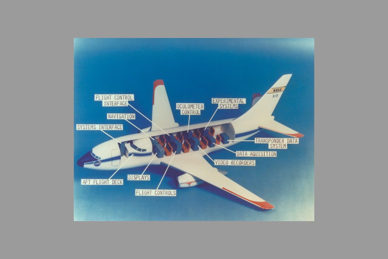
Boeing model 737 (TCV) Terminally configured vehicle cut away (ref: L80-8015)
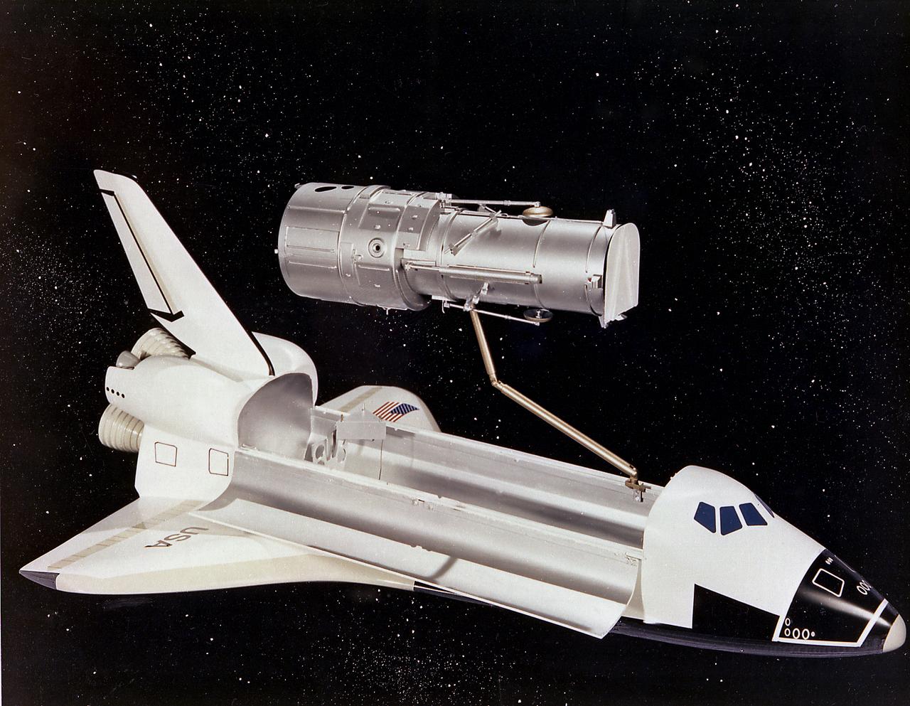
This artist's concept depicts the Hubble Space Telescope (HST) being positioned for release from the Space Shuttle orbiter by the Remote Manipulator System (RMS). The HST is the product of a partnership between NASA, European Space Agency Contractors, and the international community of astronomers. It is named after Edwin P. Hubble, an American Astronomer who discovered the expanding nature of the universe and was the first to realize the true nature of galaxies. The purpose of the HST, the most complex and sensitive optical telescope ever made, is to study the cosmos from a low-Earth orbit. By placing the telescope in space, astronomers are able to collect data that is free of the Earth's atmosphere. The HST detects objects 25 times fainter than the dimmest objects seen from Earth and provides astronomers with an observable universe 250 times larger than visible from ground-based telescopes, perhaps as far away as 14 billion light-years. The HST views galaxies, stars, planets, comets, possibly other solar systems, and even unusual phenomena such as quasars, with 10 times the clarity of ground-based telescopes. The major elements of the HST are the Optical Telescope Assembly (OTA), the Support System Module (SSM), and the Scientific Instruments (SI). The HST is 42.5-feet (13- meters) long and weighs about 25,000 pounds (11,600 kilograms). The HST was deployed from the Space Shuttle Discovery (STS-31 mission) into Earth orbit in April 1990. The Marshall Space Flight Center had responsibility for design, development, and construction of the HST. The Perkin-Elmer Corporation, in Danbury, Cornecticut, developed the optical system and guidance sensors. The Lockheed Missile and Space Company of Sunnyvale, California produced the protective outer shroud and spacecraft systems, and assembled and tested the finished telescope.

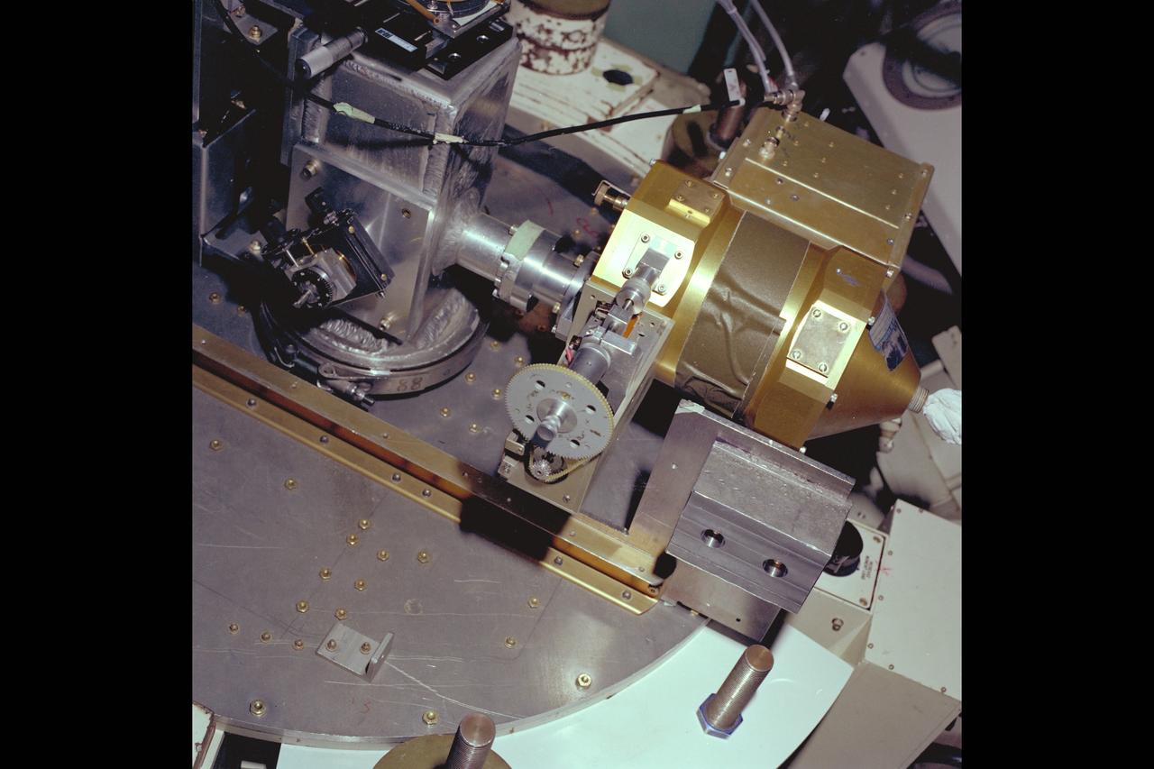
Bill Davis performing checkout at the Materials Experiment Assembly (MEA) Isothermal Furnace.

SPACE SHUTTLE ORBITER ENTERPRISE MATED TO AN EXTERNAL FUEL TANK AND TWO SOLID ROCKET BOOSTERS ON TOP OF A MOBIL LAUNCHER PLATFORM, UNDERGOES FIT AND FUNCTION CHECKS AT THE LAUNCH SITE FOR THE FIRST SPACE SHUTTLE AT LAUNCH COMPLEX 39'S PAD A. THE DUMMY SPACE SHUTTLE WAS ASSEMBLED IN THE VEHICLE ASSEMBLY BUILDING AND ROLLED OUT TO THE LAUNCH SITE ON MAY 1 AS PART OF AN EXERCISE TO MAKE CERTAIN SHUTTLE ELEMENTS ARE COMPATIBLE WITH THE SPACEPORT'S ASSEMBLY AND LAUNCH FACILITIES AND GROUND SUPPORT EQUIPMENT, AND HELP CLEAR THE WAY FOR THE LAUNCH OF THE SPACE SHUTTLE ORBITER COLUMBIA.
SPACE SHUTTLE ORBITER ENTERPRISE MATED TO AN EXTERNAL FUEL TANK AND TWO SOLID ROCKET BOOSTERS ON TOP OF A MOBIL LAUNCHER PLATFORM, UNDERGOES FIT AND FUNCTION CHECKS AT THE LAUNCH SITE FOR THE FIRST SPACE SHUTTLE AT LAUNCH COMPLEX 39'S PAD A. THE DUMMY SPACE SHUTTLE WAS ASSEMBLED IN THE VEHICLE ASSEMBLY BUILDING AND ROLLED OUT TO THE LAUNCH SITE ON MAY 1 AS PART OF AN EXERCISE TO MAKE CERTAIN SHUTTLE ELEMENTS ARE COMPATIBLE WITH THE SPACEPORT'S ASSEMBLY AND LAUNCH FACILITIES AND GROUND SUPPORT EQUIPMENT, AND HELP CLEAR THE WAY FOR THE LAUNCH OF THE SPACE SHUTTLE ORBITER COLUMBIA.
C-141 KAO: CAT experiment - compressor damage
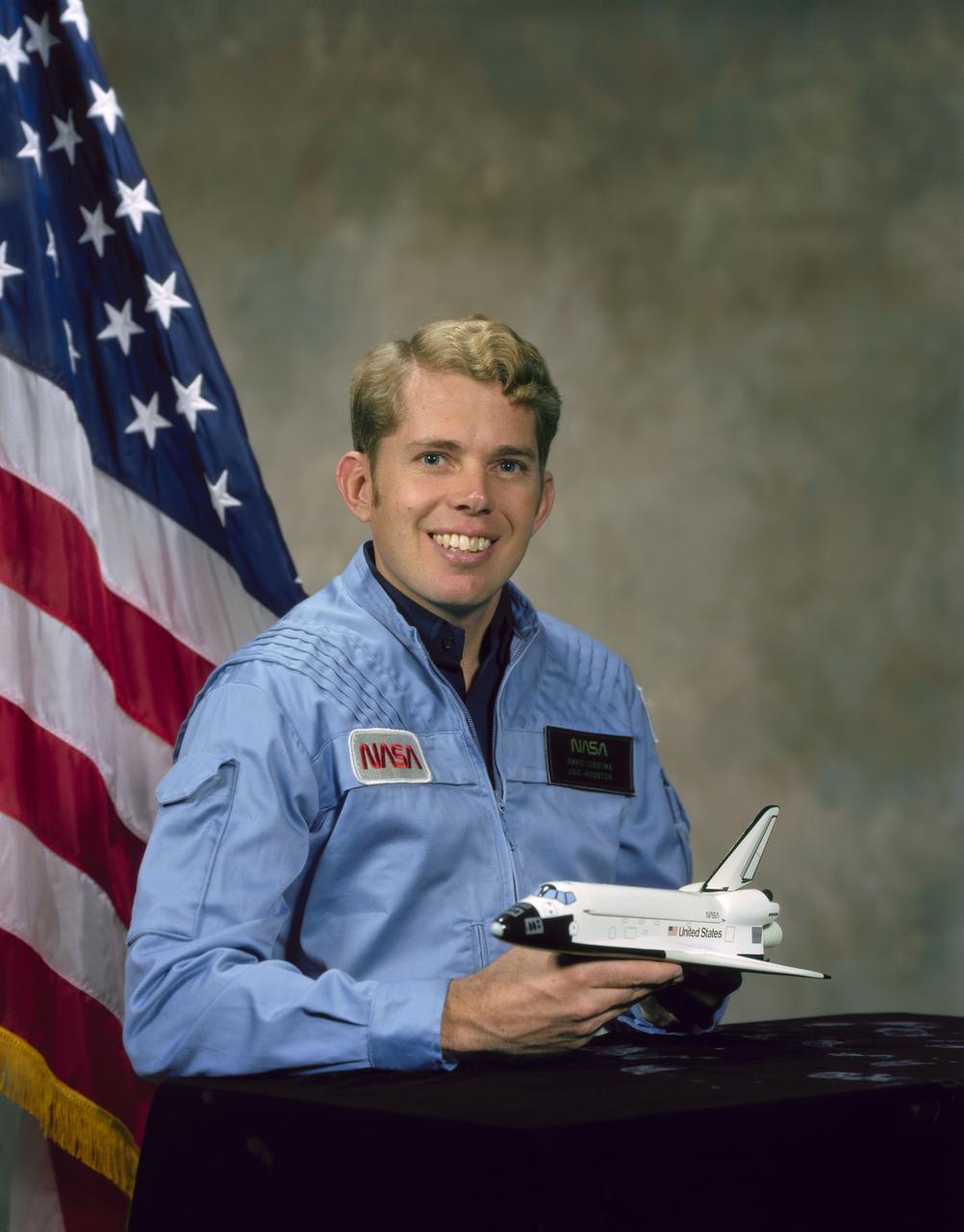
S80-42914 (Dec 1980) --- Astronaut David C. Leestma.
The Hubble Space Telescope (HST) is a cooperative program of the European Space Agency (ESA) and the National Aeronautical and Space Administration (NASA) to operate a long-lived space-based observatory. It was the flagship mission of NASA's Great Observatories program. The HST program began as an astronomical dream in the 1940s. During the 1970s and 1980s, the HST was finally designed and built becoming operational in the 1990s. The HST was deployed into a low-Earth orbit on April 25, 1990 from the cargo bay of the Space Shuttle Discovery (STS-31). The design of the HST took into consideration its length of service and the necessity of repairs and equipment replacement by making the body modular. In doing so, subsequent shuttle missions could recover the HST, replace faulty or obsolete parts and be re-released. Pictured is Marshall Space Flight Center's (MSFC's) Neutral Buoyancy Simulator (NBS) that served as the test center for shuttle astronauts training for Hubble related missions. Shown are astronauts Arna Fisher and Joe Kerwin training on a mock-up of a modular section of the HST for an axial scientific instrument changeout.
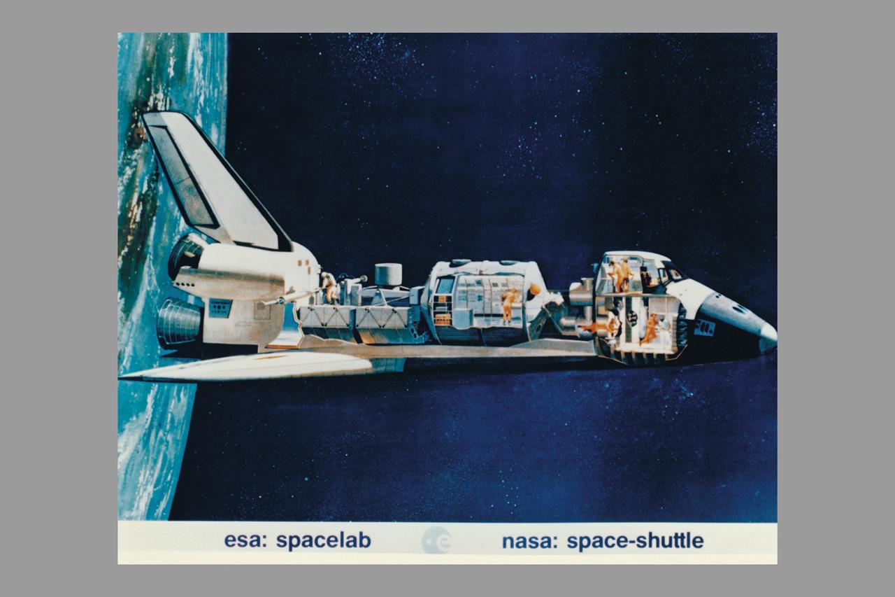
Space Shuttle cutaway showing astronauts working with ESA Spacelab
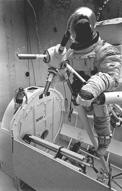
Once the United States' space program had progressed from Earth's orbit into outerspace, the prospect of building and maintaining a permanent presence in space was realized. To accomplish this feat, NASA launched a temporary workstation, Skylab, to discover the effects of low gravity and weightlessness on the human body, and also to develop tools and equipment that would be needed in the future to build and maintain a more permanent space station. The structures, techniques, and work schedules had to be carefully designed to fit this unique construction site. The components had to be lightweight for transport into orbit, yet durable. The station also had to be made with removable parts for easy servicing and repairs by astronauts. All of the tools necessary for service and repairs had to be designed for easy manipulation by a suited astronaut. Construction methods had to be efficient due to the limited time the astronauts could remain outside their controlled environment. In lieu of all the specific needs for this project, an environment on Earth had to be developed that could simulate a low gravity atmosphere. A Neutral Buoyancy Simulator (NBS) was constructed by NASA's Marshall Space Flight Center (MSFC) in 1968. Since then, NASA scientists have used this facility to understand how humans work best in low gravity and also provide information about the different kinds of structures that can be built. Pictured is a Massachusetts Institute of Technology (MIT) student working in a spacesuit on the Experimental Assembly of Structures in Extravehicular Activity (EASE) project which was developed as a joint effort between MFSC and MIT. The EASE experiment required that crew members assemble small components to form larger components, working from the payload bay of the space shuttle. The MIT student in this photo is assembling two six-beam tetrahedrons.
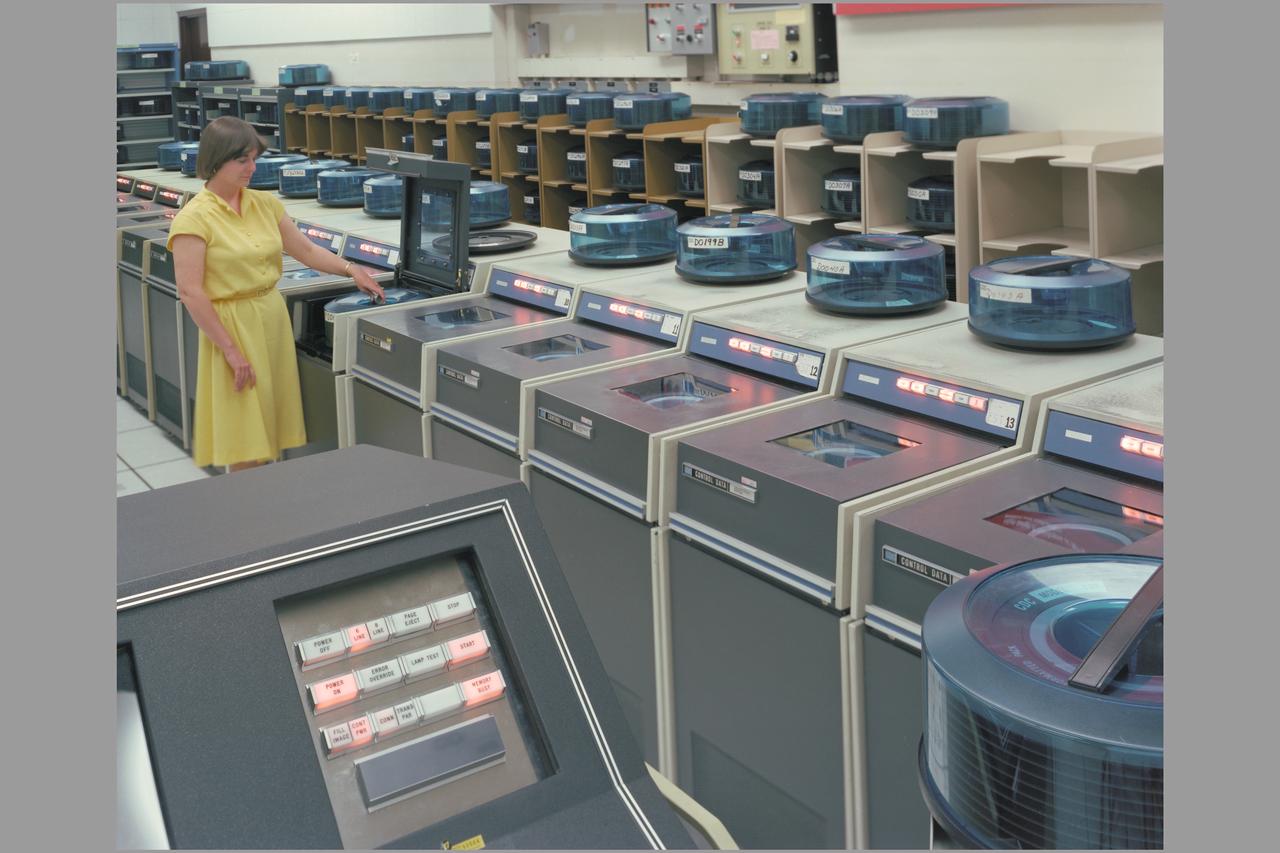
N-233 computer hardware Vax Control Data
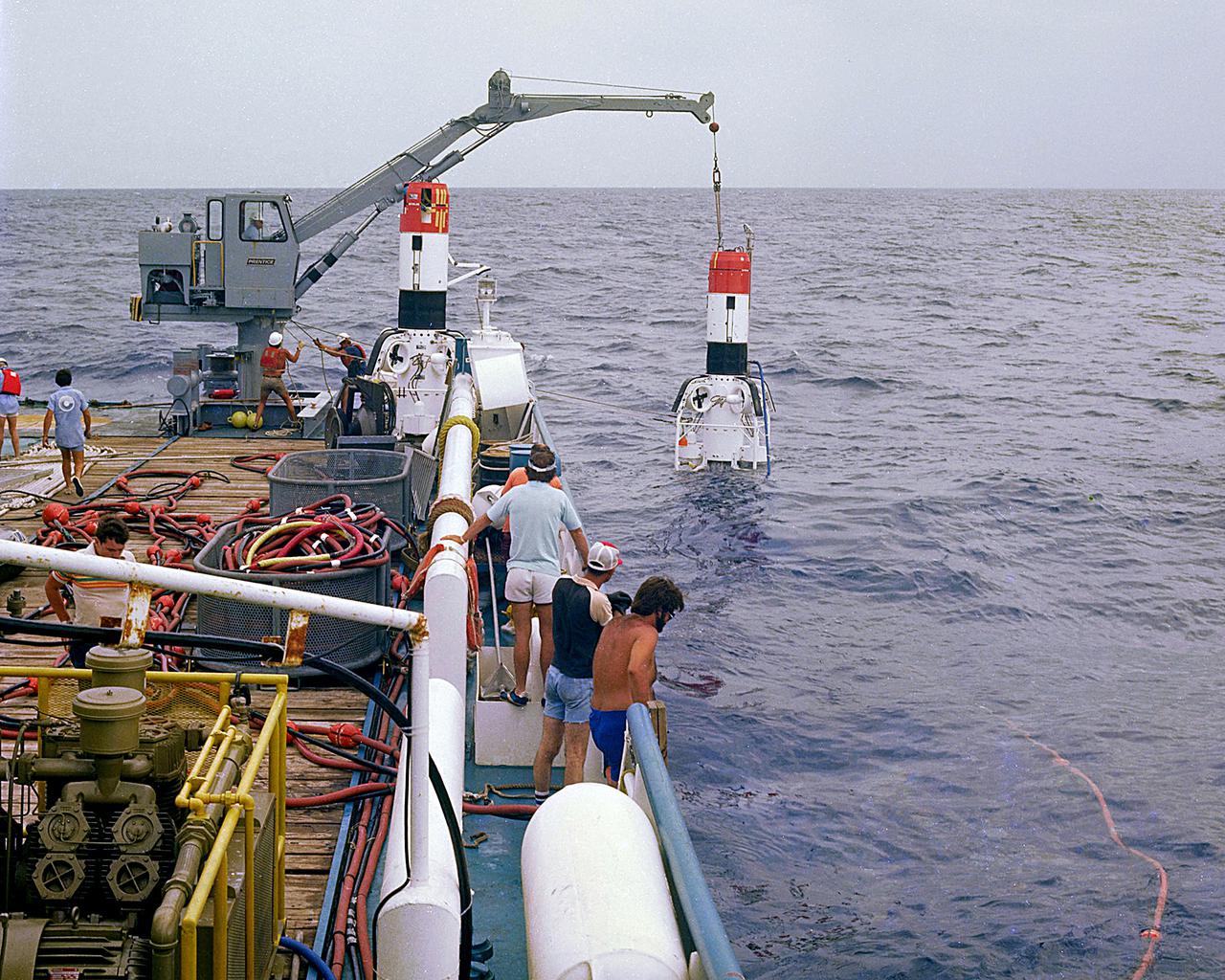
KENNEDY SPACE CENTER, FLA. - Shuttle SRB retrieval acceptance test at sea.
C-141 KAO: CAT experiment
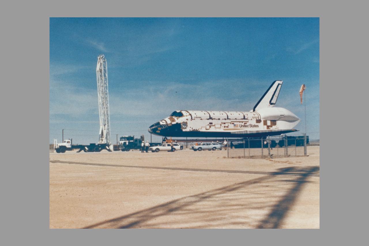
SPACE SHUTTLE ORBITER COLUMBIA 102 IS SHOWN BACKING OUT OF ITS MANUFACTURING FACILITY AT PALMDALE, CA THE ROCKWELL INTERNATIONAL SPACE DIVISION PLANT, ENROUTE TO DRYDEN FLIGHT RESEARCH CENTER. THIS ORBITER WILL BE THE FIRST SHUTTLE SPACECRAFT THAT WILL CARRY TWO ASTRONAUTS, JOHN YOUNG AND RICHARD CRIPPEN, INTO EARTH ORBITAL TEST FLIGHT IN LATE 1979.
KENNEDY SPACE CENTER, FLA. - Shuttle Orbiter Columbia lift and mate to external tank in the Vehicle Assembly Building (VAB).
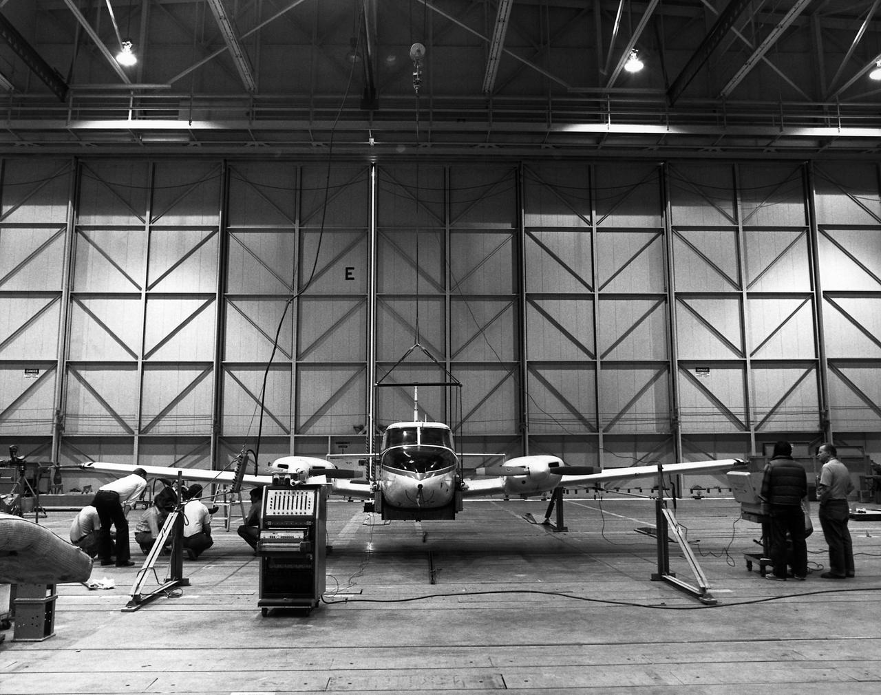
Technicians check instrumentation and systems on NASA 808, a PA-30 aircraft, prior to a research flight. The aircraft was used as the testbed in development of control systems for remotely piloted vehicles that were "flown" from the ground. The concept led to highly successful programs such as the HiMAT and the subscale F-15 remotely piloted vehicles. Over the years, NASA 808 has also been used for spin and stall research related to general aviation aircraft and also research to alleviate wake vortices behind large jetliners. This 1980 photograph taken inside a hangar shows technicians measuring moment of inertia.
KENNEDY SPACE CENTER, FLA. - Assembly of the first Space Shuttle vehicle, scheduled to make its first orbital test flight in March 1981, was completed today with the mating of the Orbiter Columbia to its eternal tank in the Vehicle Assembly Building's High Bay 3. Columbia, shown here still attached to its hoisting sling, was moved to the VAB on Nov. 24 having completed tests and tile installation in the adjacent Orbiter Processing Facility. The other Shuttle components, the twin solid rocket boosters and the external propellant tank, were stacked on the Mobile launcher Platform in High Bay 3 in January and November of this year, respectively. The current schedule calls for the rollout of the assembled Space Shuttle to Pad A at Launch Complex 39 shortly after Christmas.
SYKORSKY BEARINGLESS MAIN ROTOR TEST IN 40X80FT W.T.
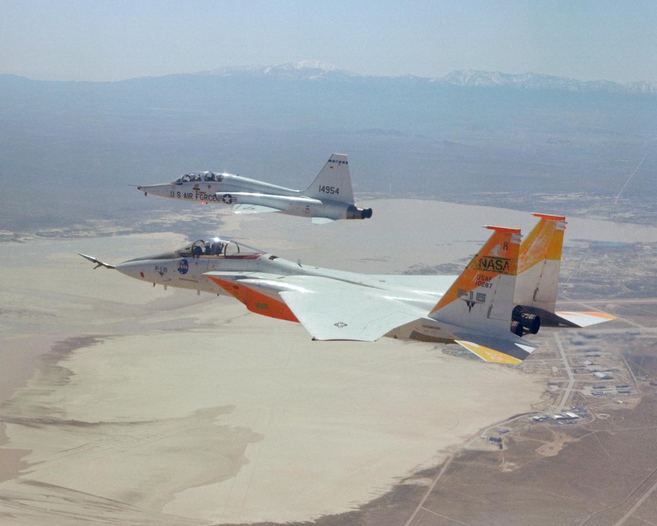
An in-flight photo of the NASA F-15A used to carry a 10 degree cone to collect aerodynamic data to calibrate the data from wind tunnels. Acting as chase for the flight was a NASA T-38 aircraft.
KENNEDY SPACE CENTER, FLA. - STS-1 arrived at Launch Complex 39A this afternoon at the end of a three-and-a-half mile journey from the Vehicle Assembly Building. The first Space Shuttle assembly will undergo an extensive series of pad validation tests and a dress rehearsal for launch - including a 20-second test firing of the orbiter’s three main engines - before being cleared for flight. The STS-1 mission, known as a shuttle systems test flight, will seek to demonstrate safe launch into orbit and safe return of the orbiter and crew and verify the combined performance of the entire shuttle vehicle -- orbiter, solid rocket boosters and external tank. STS-1 will be launched from Pad A at the Kennedy Space Center's Launch Complex 39 no earlier than March 1981.
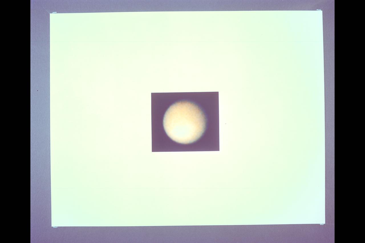
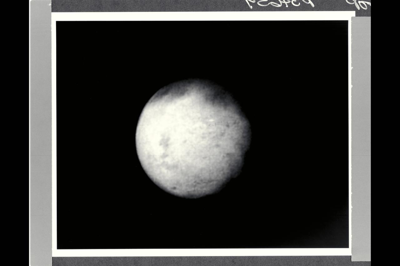
Range : 12 million km. ( 7.56 million miles) P-23057C & BW This Voyager 1 photograph of Titan, the largest of Saturn's 14 known satellites, shows little more than the upper layers of clouds covering the moon. The orange colored haze, is believed to be composed of photochemically produced hydrocarbons, hides Titan's solid surface from Voyager's camera. Some weak shadings in the clouds are becoming visible. However, note that the satellite's southern, lower, hemisphere is brighter than the northern. It is not known whether these subtle shadings are on the surface or are due to clouds below a high haze layer.
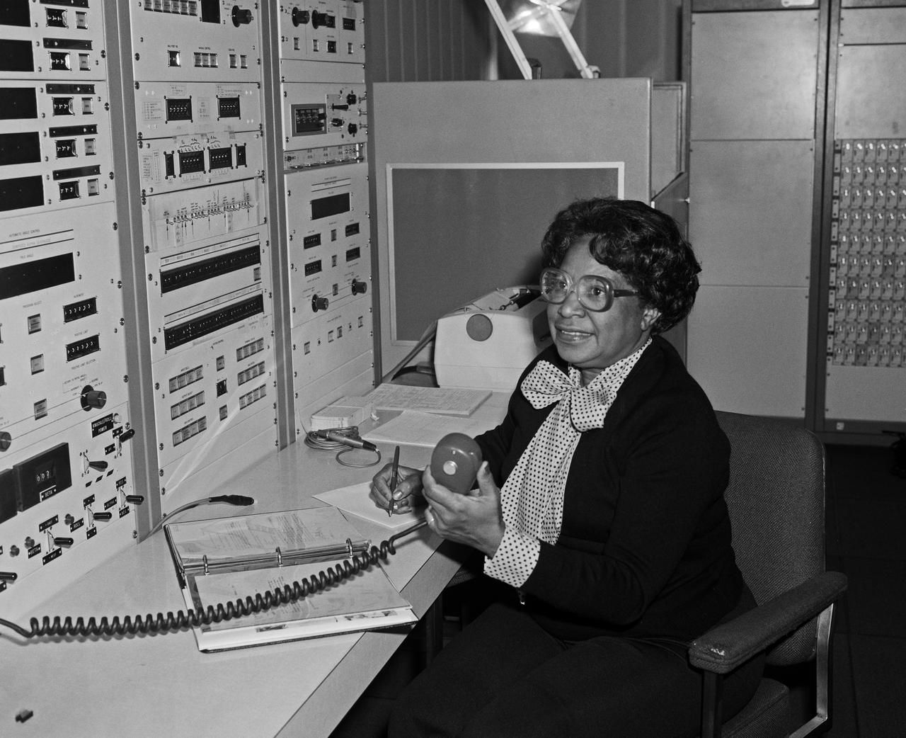
Mary Jackson at Work NASA Langley. In 1958 Mary Jackson became NASA's first black female engineer.
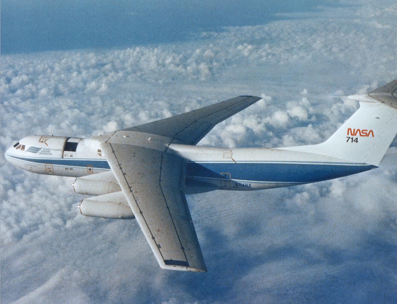
C-141 KAO in flight

S80-42916 (15 Dec. 1980) --- Astronaut Roy D. Bridges Jr., pilot.
The Hubble Space Telescope (HST) is a cooperative program of the European Space Agency (ESA) and the National Aeronautical and Space Administration (NASA) to operate a long-lived space-based observatory. It was the flagship mission of NASA's Great Observatories program. The HST program began as an astronomical dream in the 1940s. During the 1970s and 1980s, the HST was finally designed and built becoming operational in the 1990s. The HST was deployed into a low-Earth orbit on April 25, 1990 from the cargo bay of the Space Shuttle Discovery (STS-31). The design of the HST took into consideration its length of service and the necessity of repairs and equipment replacement by making the body modular. In doing so, subsequent shuttle missions could recover the HST, replace faulty or obsolete parts and be re-released. Pictured is Marshall Space Flight Center's (MSFC's) Neutral Buoyancy Simulator (NBS) that served as the test center for shuttle astronauts training for Hubble related missions. Shown are astronauts Arna Fisher and Joe Kerwin training on a mock-up of a modular section of the HST for an axial scientific instrument changeout.
KENNEDY SPACE CENTER, FLA. - STS-1 inches slowlly out of the Vehcile Assembly building shortly after 8 a.m. today to begin a 3.5-mile journey to Complex 39's Pad A. The first Space Shuttle assembly to be prepared for flight was on the hardstand at Pad A in mid-afternoon. Launch is scheduled for no earlier than March 1981.
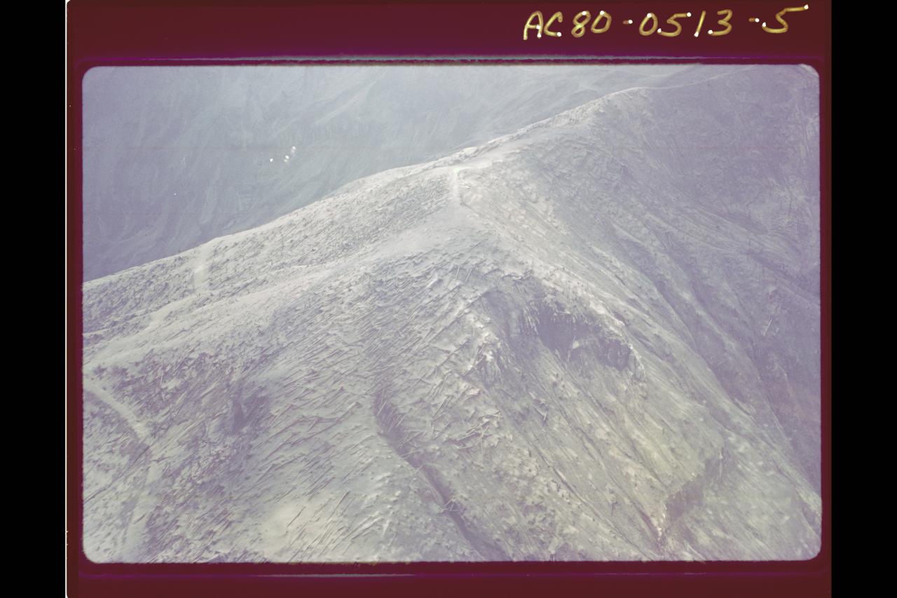
Mt. St. Helens Volcano - post eruption, forest damage
Range : 660,000 kilometers (400,000 miles) Time : 5:05 am PST This Voyager 1 picture of Mimas shows a large impact structure at 110 degrees W Long., located on that face of the moon which leads Mimas in its orbit. The feature, about 130 kilometers in diameter (80 miles), is more than 1/4 the diameter of the entire moon. This is a particularly interesting feature in view of its large diameter compared with the size of the satellite, and may have the largest crater diameter/satillite diameter ratio in the solar system. The crater has a raised rim and central peak, typical of large impact structures on terrestrial planets. Additional smaller craters, 15-45 kilometers in diameter, can be seen scattered across the surface, particularly alon the terminator. Mimas is one of the smaller Saturnian satellites with a low density implying its chief component is ice.
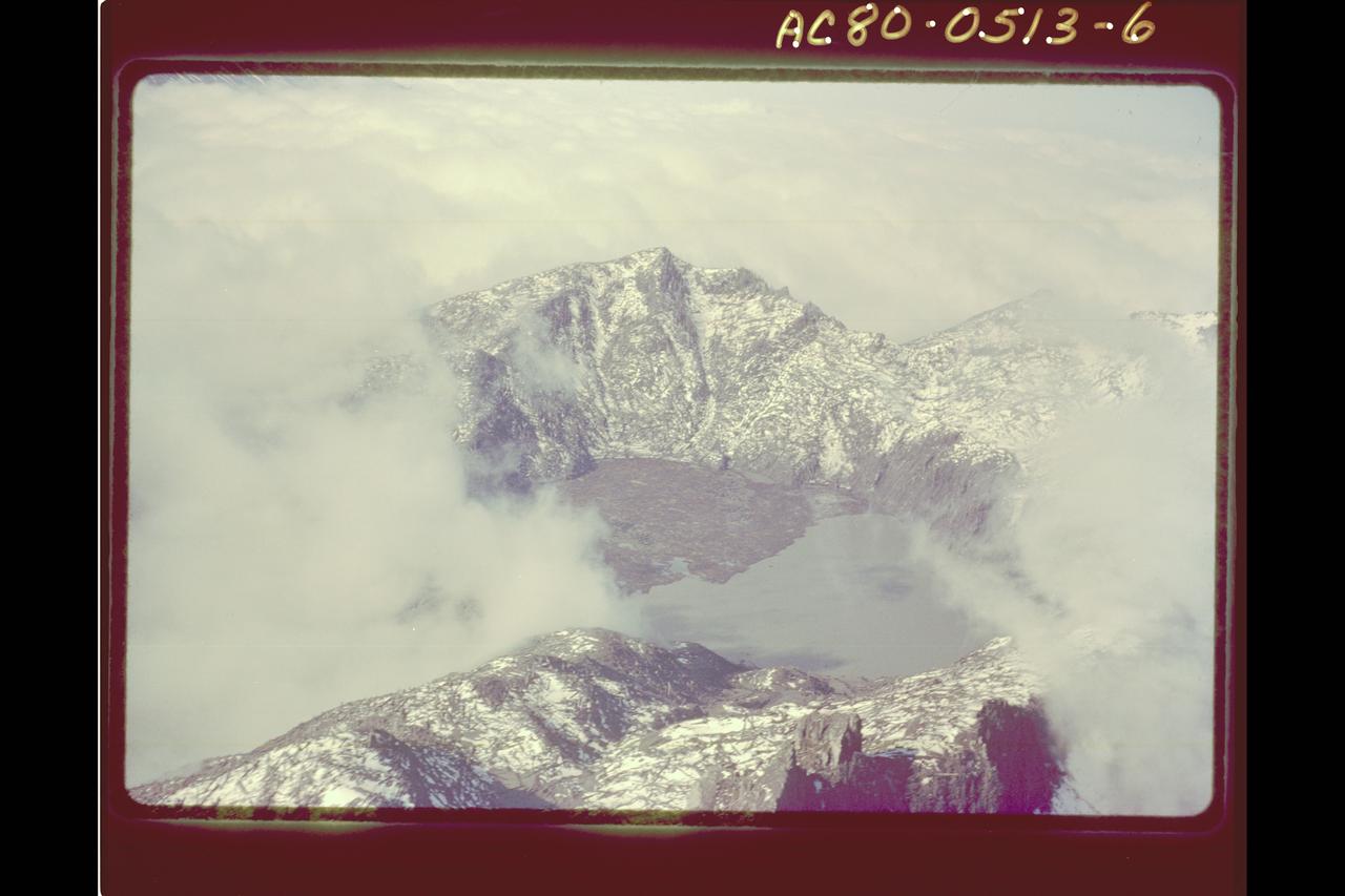
Mt. St. Helens Volcano - post eruption