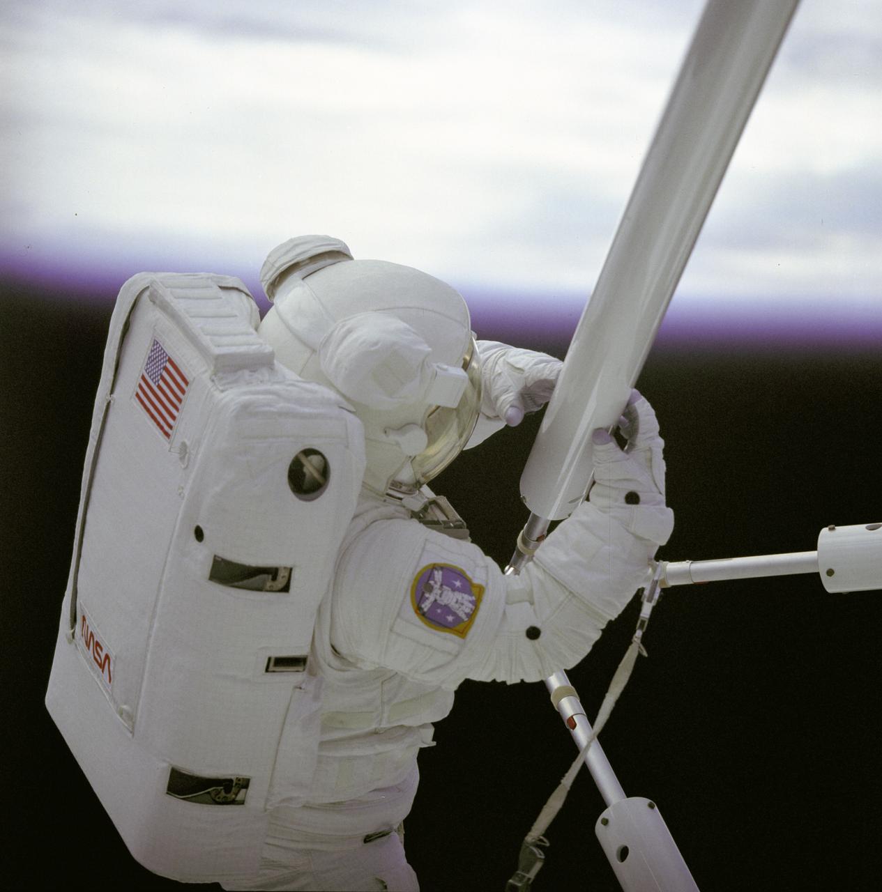
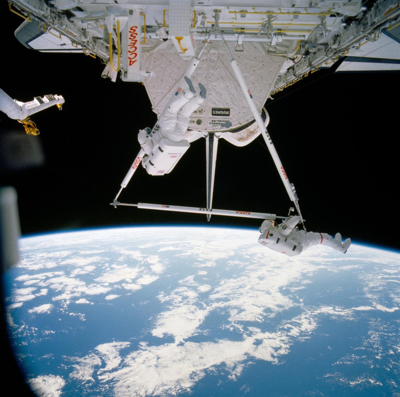
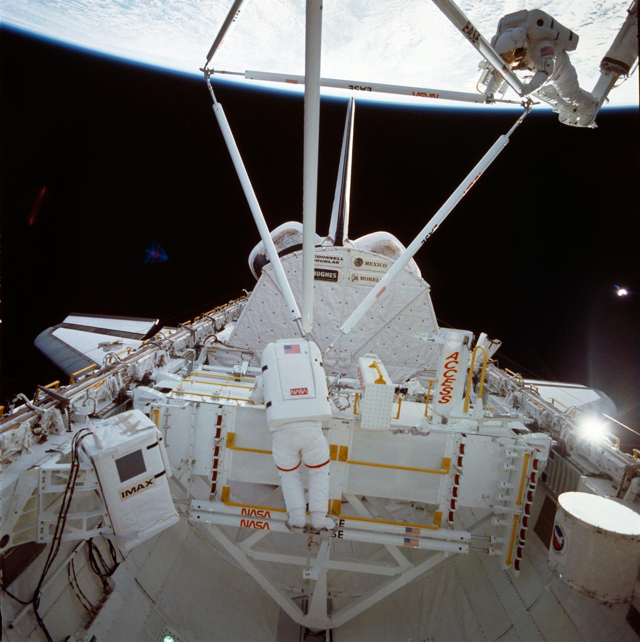
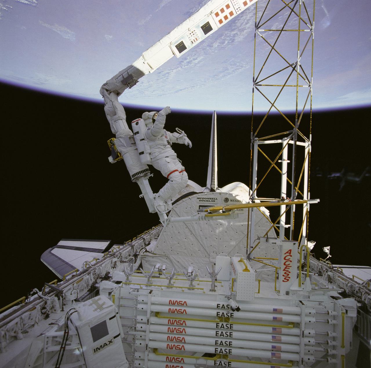
The crew assigned to the STS-61B mission included Bryan D. O’Conner, pilot; Brewster H. Shaw, commander; Charles D. Walker, payload specialist; mission specialists Jerry L. Ross, Mary L. Cleave, and Sherwood C. Spring; and Rodolpho Neri Vela, payload specialist. Launched aboard the Space Shuttle Atlantis November 28, 1985 at 7:29:00 pm (EST), the STS-61B mission’s primary payload included three communications satellites: MORELOS-B (Mexico); AUSSAT-2 (Australia); and SATCOM KU-2 (RCA Americom). Two experiments were conducted to test assembling erectable structures in space: EASE (Experimental Assembly of Structures in Extravehicular Activity), and ACCESS (Assembly Concept for Construction of Erectable Space Structure). In a joint venture between NASA/Langley Research Center in Hampton, Virginia, and the Marshall Space Flight Center (MSFC), the EASE and ACCESS were developed and demonstrated at MSFC's Neutral Buoyancy Simulator (NBS). In this STS-61B onboard photo, astronaut Spring was working on the EASE during an Extravehicular Activity (EVA). The primary objective of this experiment was to test the structural assembly concepts for suitability as the framework for larger space structures and to identify ways to improve the productivity of space construction.
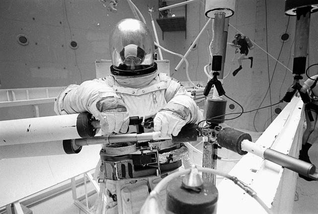
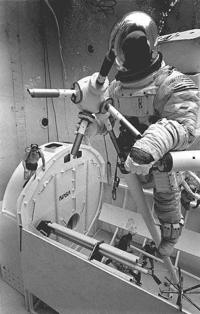
Once the United States' space program had progressed from Earth's orbit into outerspace, the prospect of building and maintaining a permanent presence in space was realized. To accomplish this feat, NASA launched a temporary workstation, Skylab, to discover the effects of low gravity and weightlessness on the human body, and also to develop tools and equipment that would be needed in the future to build and maintain a more permanent space station. The structures, techniques, and work schedules had to be carefully designed to fit this unique construction site. The components had to be lightweight for transport into orbit, yet durable. The station also had to be made with removable parts for easy servicing and repairs by astronauts. All of the tools necessary for service and repairs had to be designed for easy manipulation by a suited astronaut. Construction methods had to be efficient due to the limited time the astronauts could remain outside their controlled environment. In lieu of all the specific needs for this project, an environment on Earth had to be developed that could simulate a low gravity atmosphere. A Neutral Buoyancy Simulator (NBS) was constructed by NASA's Marshall Space Flight Center (MSFC) in 1968. Since then, NASA scientists have used this facility to understand how humans work best in low gravity and also provide information about the different kinds of structures that can be built. Pictured is a Massachusetts Institute of Technology (MIT) student working in a spacesuit on the Experimental Assembly of Structures in Extravehicular Activity (EASE) project which was developed as a joint effort between MFSC and MIT. The EASE experiment required that crew members assemble small components to form larger components, working from the payload bay of the space shuttle. The MIT student in this photo is assembling two six-beam tetrahedrons.
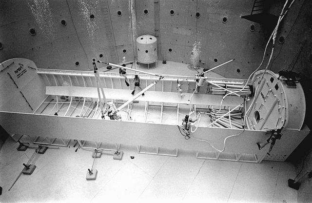
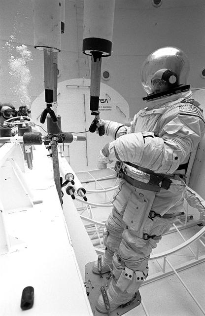
Once the United States' space program had progressed from Earth's orbit into outerspace, the prospect of building and maintaining a permanent presence in space was realized. To accomplish this feat, NASA launched a temporary workstation, Skylab, to discover the effects of low gravity and weightlessness on the human body, and also to develop tools and equipment that would be needed in the future to build and maintain a more permanent space station. The structures, techniques, and work schedules had to be carefully designed to fit this unique construction site. The components had to be lightweight for transport into orbit, yet durable. The station also had to be made with removable parts for easy servicing and repairs by astronauts. All of the tools necessary for service and repairs had to be designed for easy manipulation by a suited astronaut. Construction methods had to be efficient due to the limited time the astronauts could remain outside their controlled environment. In lieu of all the specific needs for this project, an environment on Earth had to be developed that could simulate a low gravity atmosphere. A Neutral Buoyancy Simulator (NBS) was constructed by NASA Marshall Space Flight Center (MSFC) in 1968. Since then, NASA scientists have used this facility to understand how humans work best in low gravity and also provide information about the different kinds of structures that can be built. As part of this experimentation, the Experimental Assembly of Structures in Extravehicular Activity (EASE) project was developed as a joint effort between MFSC and the Massachusetts Institute of Technology (MIT). The EASE experiment required that crew members assemble small components to form larger components, working from the payload bay of the space shuttle. Pictured is an entire unit that has been constructed and is sitting in the bottom of a mock-up shuttle cargo bay pallet.
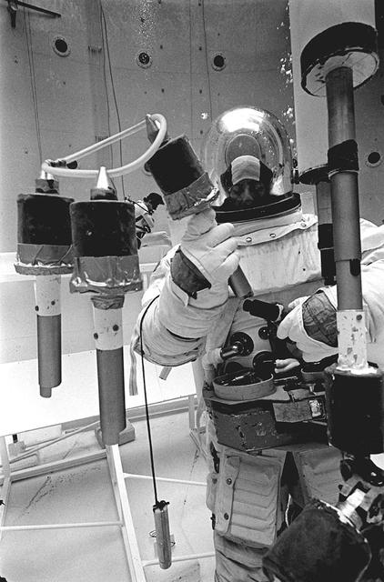
Once the United States' space program had progressed from Earth's orbit into outerspace, theprospect of building and maintaining a permanent presence in space was realized. To accomplish this feat, NASA launched a temporary workstation, Skylab, to discover the effects of low gravity and weightlessness on the human body, and also to develop tools and equipment that would be needed in the future to build and maintain a more permanent space station. The structures, techniques, and work schedules had to be carefully designed to fit this unique construction site. The components had to be lightweight for transport into orbit, yet durable. The station also had to be made with removable parts for easy servicing and repairs by astronauts. All of the tools necessary for service and repairs had to be designed for easy manipulation by a suited astronaut. Construction methods had to be efficient due to the limited time the astronauts could remain outside their controlled environment. In lieu of all the specific needs for this project, an environment on Earth had to be developed that could simulate a low gravity atmosphere. A Neutral Buoyancy Simulator (NBS) was constructed by NASA's Marshall Space Flight Center (MSFC) in 1968. Since then, NASA scientists have used this facility to understand how humans work best in low gravity and also provide information about the different kinds of structures that can be built. Pictured is a Massachusetts Institute of Technology (MIT) student working in a spacesuit on the Experimental Assembly of Structures in Extravehicular Activity (EASE) project which was developed as a joint effort between MFSC and MIT. The EASE experiment required that crew members assemble small components to form larger components, working from the payload bay of the space shuttle. The MIT student in this photo is assembling two six-beam tetrahedrons.
Once the United States' space program had progressed from Earth's orbit into outerspace, the prospect of building and maintaining a permanent presence in space was realized. To accomplish this feat, NASA launched a temporary workstation, Skylab, to discover the effects of low gravity and weightlessness on the human body, and also to develop tools and equipment that would be needed in the future to build and maintain a more permanent space station. The structures, techniques, and work schedules had to be carefully designed to fit this unique construction site. The components had to be lightweight for transport into orbit, yet durable. The station also had to be made with removable parts for easy servicing and repairs by astronauts. All of the tools necessary for service and repairs had to be designed for easy manipulation by a suited astronaut. Construction methods had to be efficient due to the limited time the astronauts could remain outside their controlled environment. In lieu of all the specific needs for this project, an environment on Earth had to be developed that could simulate a low gravity atmosphere. A Neutral Buoyancy Simulator (NBS) was constructed by NASA's Marshall Space Flight Center (MSFC) in 1968. Since then, NASA scientists have used this facility to understand how humans work best in low gravity and also provide information about the different kinds of structures that can be built. Pictured is a Massachusetts Institute of Technology (MIT) student working in a spacesuit on the Experimental Assembly of Structures in Extravehicular Activity (EASE) project which was developed as a joint effort between MFSC and MIT. The EASE experiment required that crew members assemble small components to form larger components, working from the payload bay of the space shuttle. The MIT student in this photo is assembling two six-beam tetrahedrons.
Once the United States' space program had progressed from Earth's orbit into outerspace, the prospect of building and maintaining a permanent presence in space was realized. To accomplish this feat, NASA launched a temporary workstation, Skylab, to discover the effects of low gravity and weightlessness on the human body, and also to develop tools and equipment that would be needed in the future to build and maintain a more permanent space station. The structures, techniques, and work schedules had to be carefully designed to fit this unique construction site. The components had to be lightweight for transport into orbit, yet durable. The station also had to be made with removable parts for easy servicing and repairs by astronauts. All of the tools necessary for service and repairs had to be designed for easy manipulation by a suited astronaut. Construction methods had to be efficient due to the limited time the astronauts could remain outside their controlled environment. In lieu of all the specific needs for this project, an environment on Earth had to be developed that could simulate a low gravity atmosphere. A Neutral Buoyancy Simulator (NBS) was constructed by NASA's Marshall Space Flight Center (MSFC) in 1968. Since then, NASA scientists have used this facility to understand how humans work best in low gravity and also provide information about the different kinds of structures that can be built. Pictured is a Massachusetts Institute of Technology (MIT) student working in a spacesuit on the Experimental Assembly of Structures in Extravehicular Activity (EASE) project which was developed as a joint effort between MFSC and MIT. The EASE experiment required that crew members assemble small components to form larger components, working from the payload bay of the space shuttle. The MIT student in this photo is assembling two six-beam tetrahedrons.

NASA Terra spacecraft shows the water flow after the U.S. Army Corps of Engineers opened the Morganza Spillway, a flood control structure along the western bank of the Mississippi River in Louisiana, to ease flooding along levee systems on May 14, 2011.
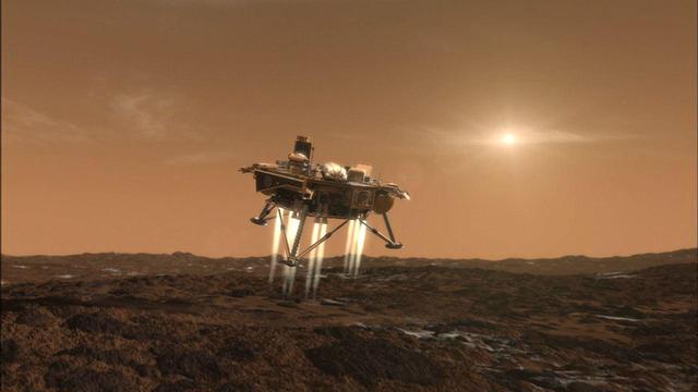
This artist conception depicts NASA Phoenix Mars Lander a moment before its touchdown on the arctic plains of Mars.
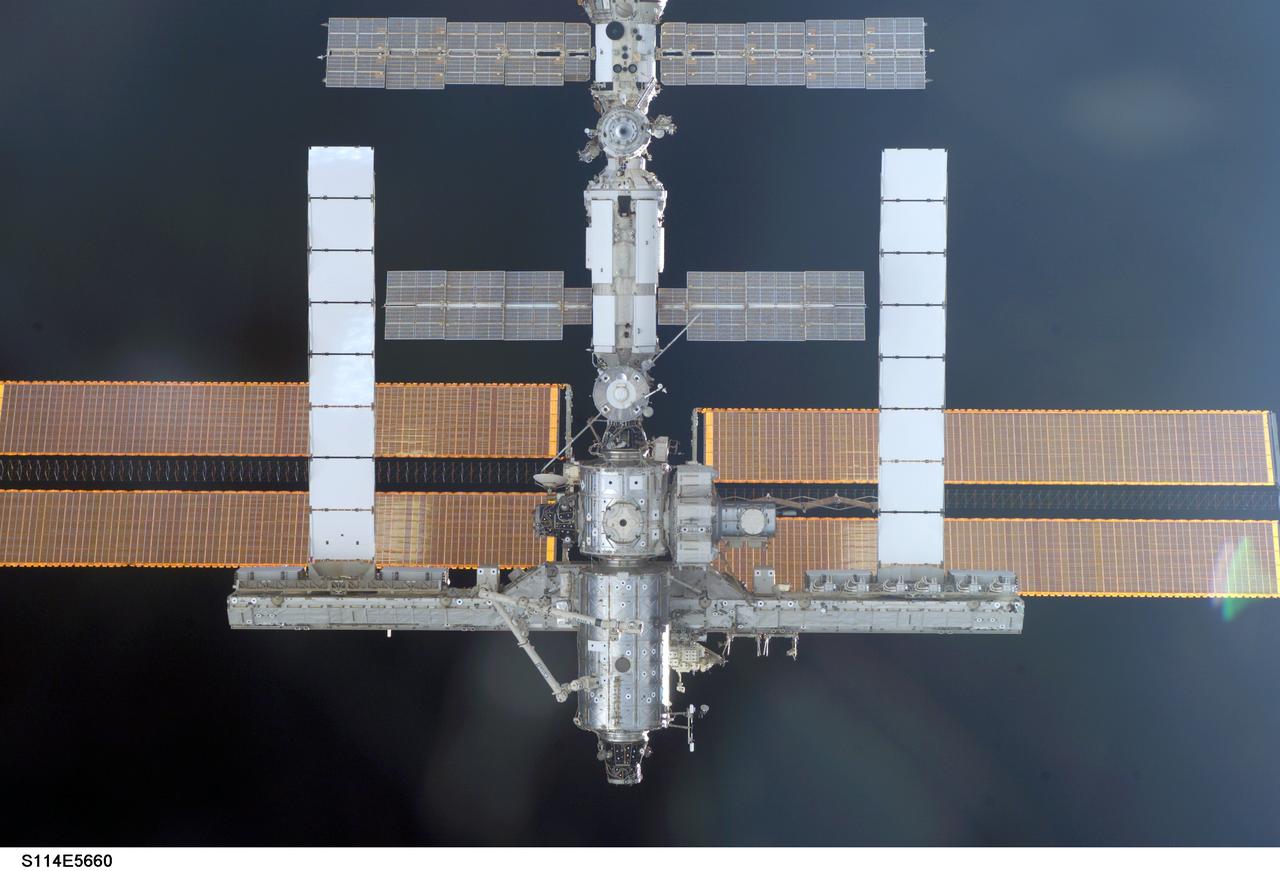
S114-E-5660 (28 July 2005) --- This image of the International Space Station easing toward the Space Shuttle Discovery was photographed by one of the STS-114 astronauts in the orbiter's crew cabin.
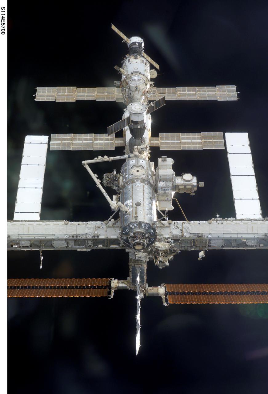
S114-E-5700 (28 July 2005) --- This image of the International Space Station easing toward the Space Shuttle Discovery was photographed by one of the STS-114 astronauts in the orbiter's crew cabin.

S114-E-5676 (28 July 2005) --- This image of the International Space Station easing toward the Space Shuttle Discovery was photographed by one of the STS-114 astronauts in the orbiter's crew cabin.
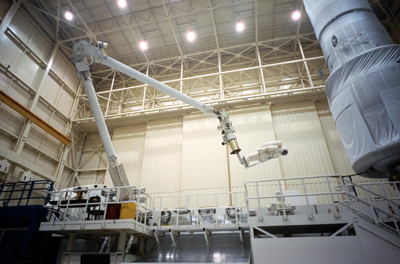
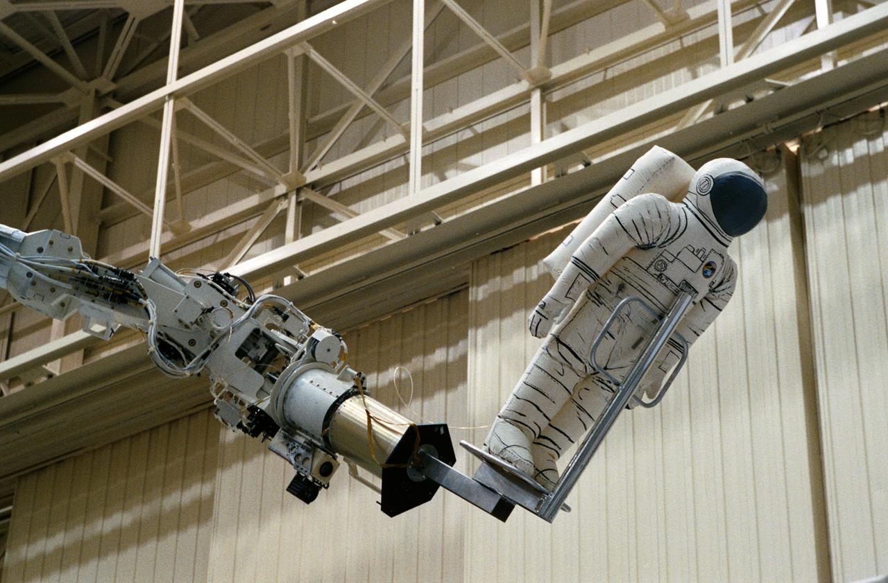
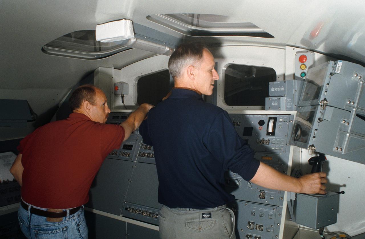
The Remote Manipulator System (RMS) eases a mannequin representing an astronaut into position for an STS-61 Hubble Space Telescope (HST) servicing task in the Space Shuttle mockup and integration laboratory at JSC (35699, 35703); Wide-angle view of the RMS easing a mannequin into position for work on the HST mock-up in bldg 9N (35700-1); Swiss scientist Claude Nicollier, mission specialist, works the control of the RMS during a training session in the manipulator development facility (MDF) in JSC's Shuttle mock-up and integration laboratory. Astronaut Kenneth D. Bowersox (left), pilot, is among the other crewmembers in training for the STS-61 HST servicing mission (35702).
The Remote Manipulator System (RMS) eases a mannequin representing an astronaut into position for an STS-61 Hubble Space Telescope (HST) servicing task in the Space Shuttle mockup and integration laboratory at JSC (35699, 35703); Wide-angle view of the RMS easing a mannequin into position for work on the HST mock-up in bldg 9N (35700-1); Swiss scientist Claude Nicollier, mission specialist, works the control of the RMS during a training session in the manipulator development facility (MDF) in JSC's Shuttle mock-up and integration laboratory. Astronaut Kenneth D. Bowersox (left), pilot, is among the other crewmembers in training for the STS-61 HST servicing mission (35702).
The Remote Manipulator System (RMS) eases a mannequin representing an astronaut into position for an STS-61 Hubble Space Telescope (HST) servicing task in the Space Shuttle mockup and integration laboratory at JSC (35699, 35703); Wide-angle view of the RMS easing a mannequin into position for work on the HST mock-up in bldg 9N (35700-1); Swiss scientist Claude Nicollier, mission specialist, works the control of the RMS during a training session in the manipulator development facility (MDF) in JSC's Shuttle mock-up and integration laboratory. Astronaut Kenneth D. Bowersox (left), pilot, is among the other crewmembers in training for the STS-61 HST servicing mission (35702).
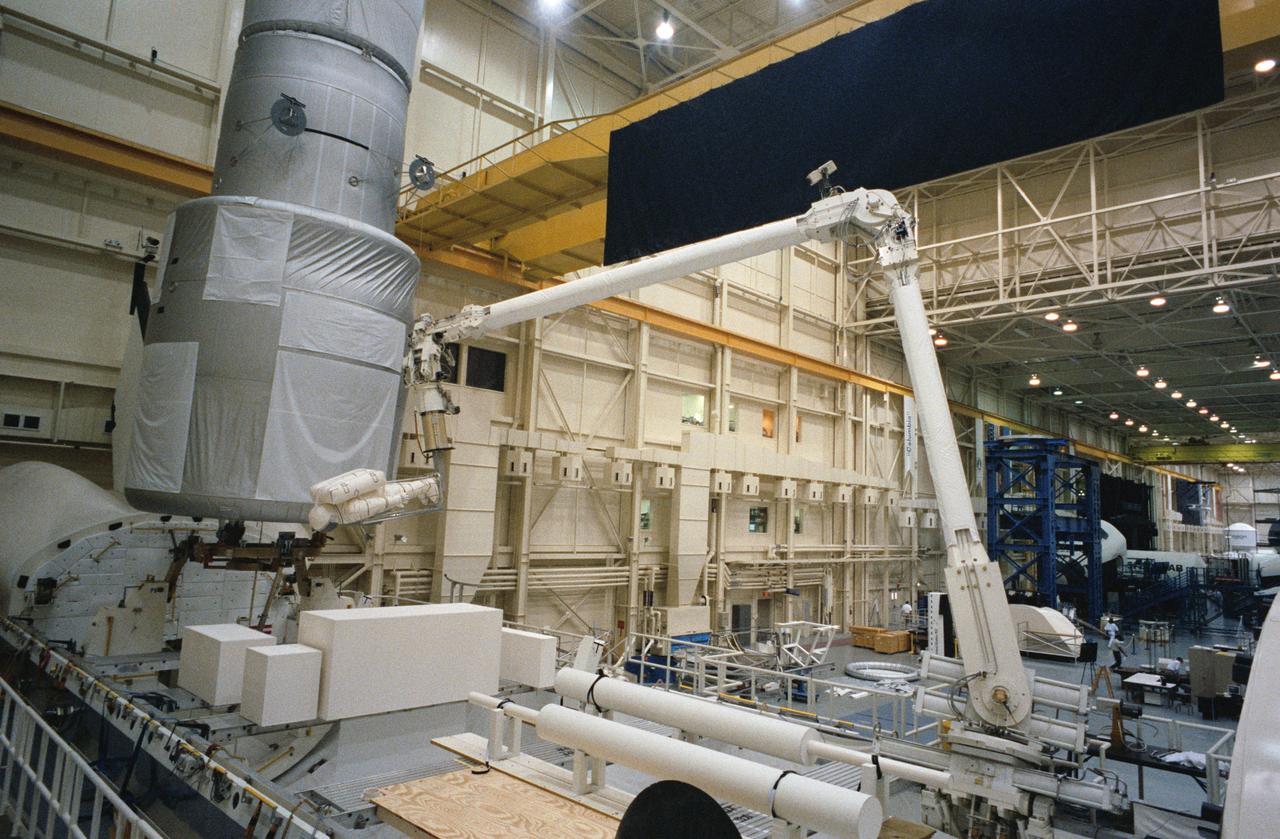
The Remote Manipulator System (RMS) eases a mannequin representing an astronaut into position for an STS-61 Hubble Space Telescope (HST) servicing task in the Space Shuttle mockup and integration laboratory at JSC (35699, 35703); Wide-angle view of the RMS easing a mannequin into position for work on the HST mock-up in bldg 9N (35700-1); Swiss scientist Claude Nicollier, mission specialist, works the control of the RMS during a training session in the manipulator development facility (MDF) in JSC's Shuttle mock-up and integration laboratory. Astronaut Kenneth D. Bowersox (left), pilot, is among the other crewmembers in training for the STS-61 HST servicing mission (35702).
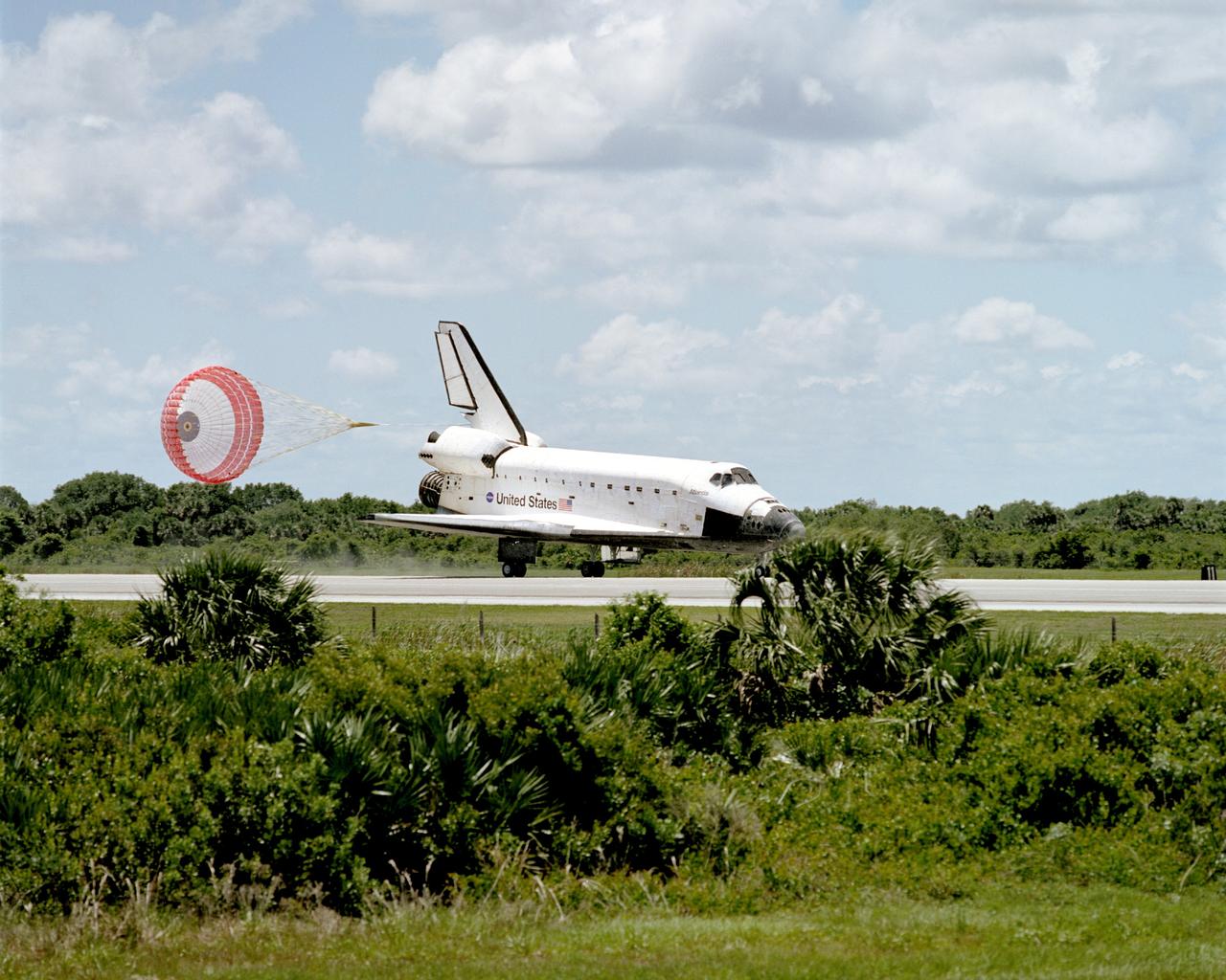
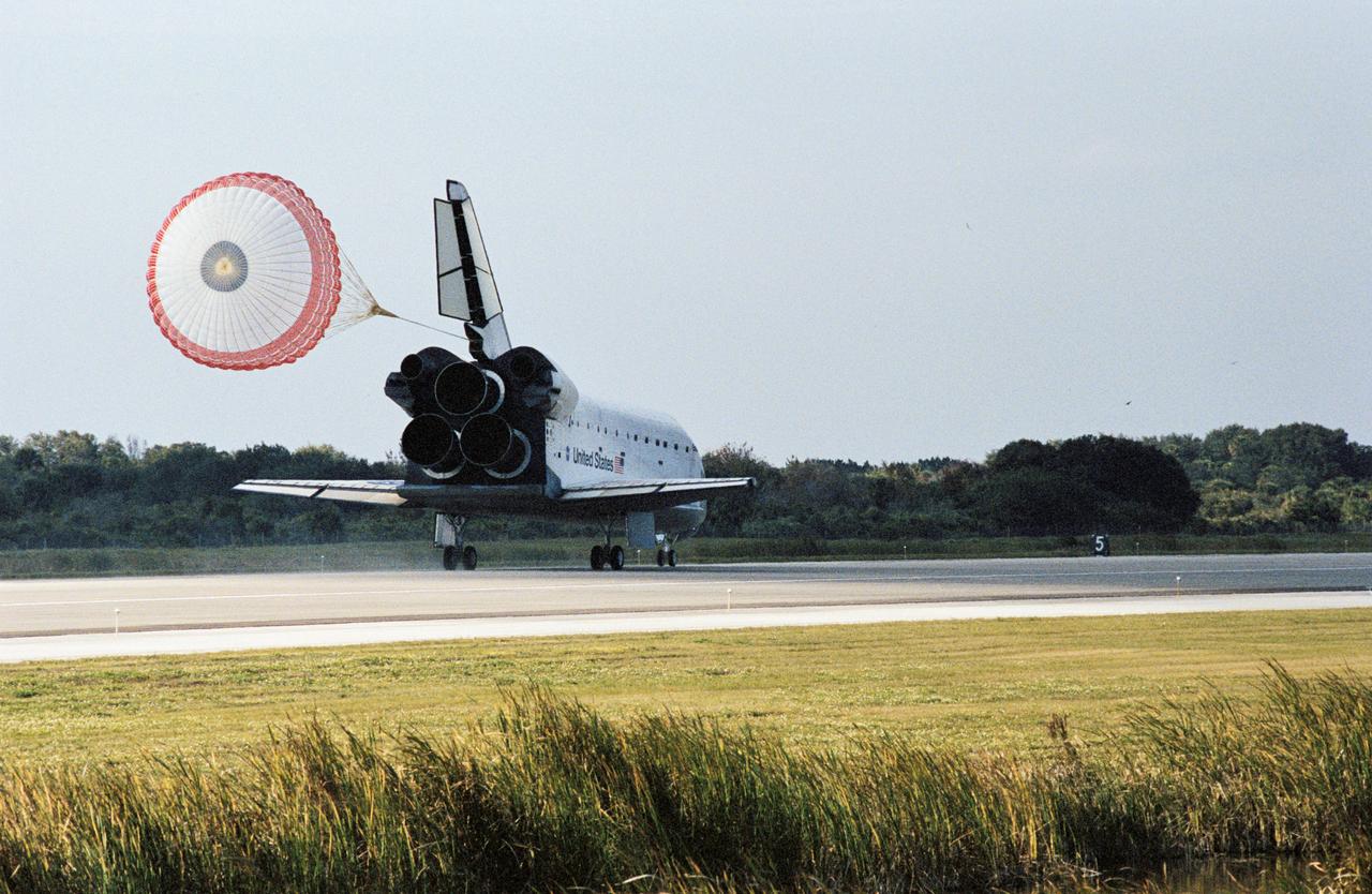
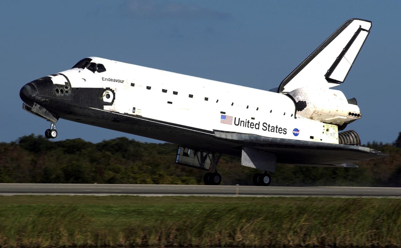
STS110-S-055 (19 April 2002) --- With its drag chute gear deployed, the Space Shuttle Atlantis eases to a stop on the runway at the KSC landing facility to complete the nearly 11-day STS-110 journey. Astronaut Michael J. Bloomfield, mission commander, eased Atlantis to a textbook landing on runway 3-3 at the Florida spaceport at 12:27 p.m. (EDT), April 19, 2002, under clear skies and light winds. The landing completed a 4.5-million-mile mission that saw successful delivery and installation of the centerpiece of the International Space Station?s main truss and the inaugural run of the first space railcar, the Mobile Transporter.
Astronauts Jerry L. Ross (left) and Sherwood C. (Woody) Spring are photographed as they assemble pieces of the Experimental Assembly of Structures in Extravehicular Activities (EASE) device in the open payload bay. The Canadian-built remote manipulator system (RMS) arm (partially obscured in the right portion of the frame) is in position to allow television cameras to record the activity.
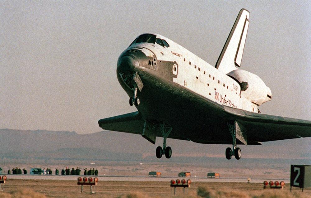
Space Shuttle Discovery STS-42) is just about to ease down its main gear on Runway 22 at Edwards Air Force Base in southern California. The successful landing completed an eight-day mission for five NASA astronauts and two payload specialists supporting the first International Microgravity Laboratory (IML-1) mission.
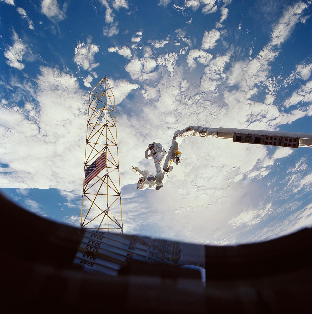
Astronauts Jerry L. Ross (right) and Sherwood C. (Woody) Spring (left) share a foot restraint as they survey the assembled ACCESS components after a lengthy extravehicular activity. Both men salute the American flag placed on the assembled ACCESS tower. Stowed EASE pieces are reflected in the window through which the photo was taken.
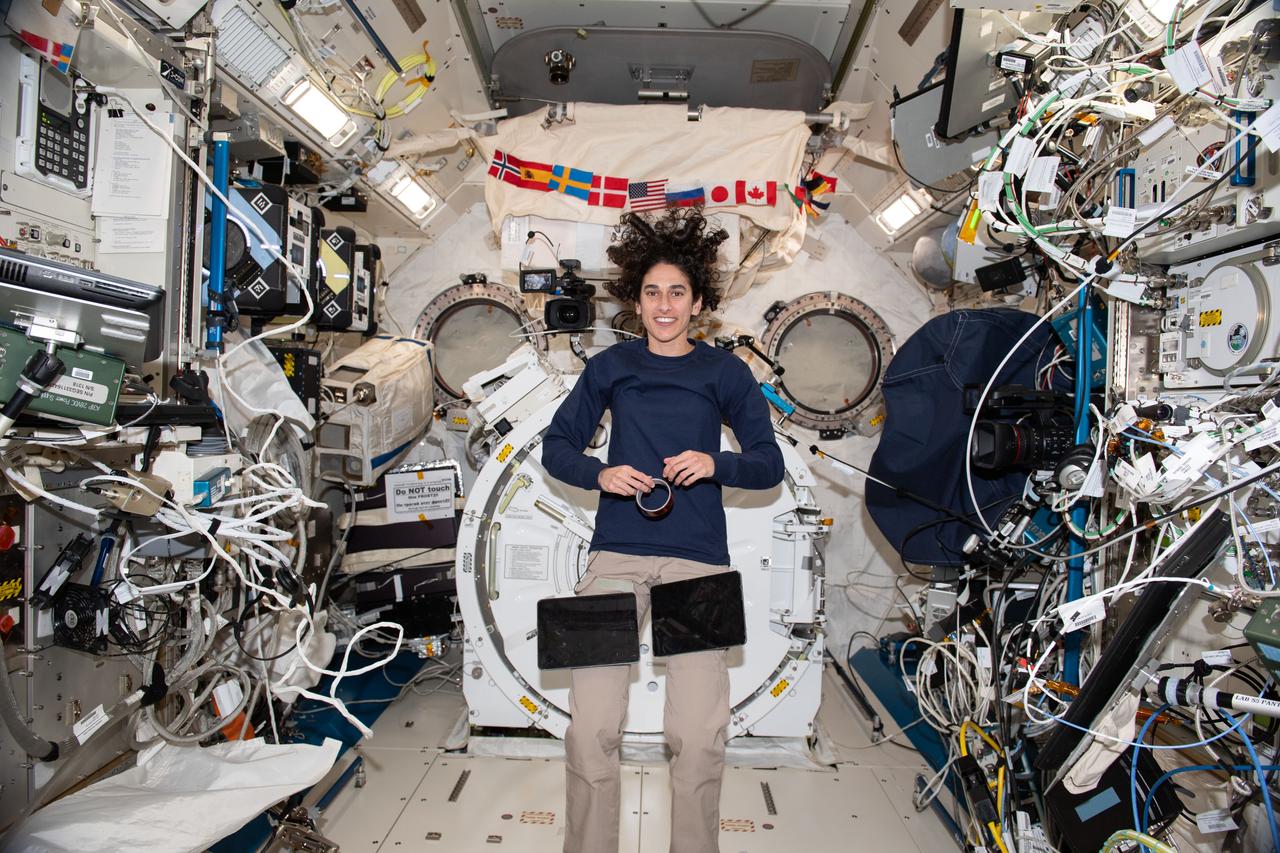
iss070e035105 (Nov. 30, 2023) --- NASA astronaut and Expedition 70 Flight Engineer Jasmin Moghbeli takes a break during operations and poses for a portrait inside the International Space Station's Kibo laboratory module. A pair of computer tablets are attached to velcro straps on Moghbeli's pants for ease of access when reviewing procedures and instructions.
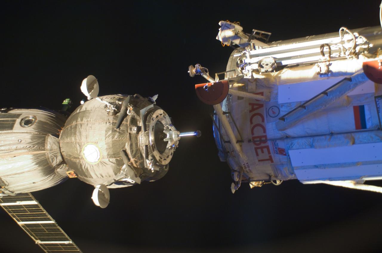
ISS030-E-015605 (23 Dec. 2011) --- With the three Expedition 30/31 crew members aboard, the Soyuz TMA-03M spacecraft (left) eases toward its docking with the Russian-built Mini-Research Module 1 (MRM-1), also known as Rassvet, Russian for "dawn." The docking, which once more enables six astronauts and cosmonauts to work together aboard the Earth-orbiting International Space Station, took place at 9:19 a.m. (CST) on Dec. 23, 2011.
jsc2020e008566 (12/31/2013) --- Lockheed Martin engineer Robert Benzio conducts a fit check with two Rodent Research modules at NASA's Ames Research Center in Moffett Field, California. The Rodent Research Facility provides rodent housing on board the International Space Station (ISS). Animal research is essential for understanding the impacts of spaceflight on the systems of the human body, and for development of potential therapies that will ease harmful responses to space flight. Credits: NASA/Dominic Hart
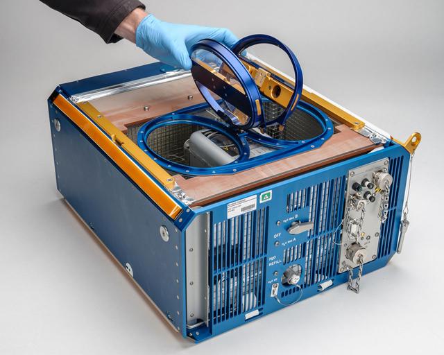
jsc2020e008565 (12/27/2013) --- NASA’s Rodent Habitat module with both access doors open. The Rodent Research Facility provides rodent housing on board the International Space Station (ISS). Animal research is essential for understanding the impacts of spaceflight on the systems of the human body, and for development of potential therapies that will ease harmful responses to space flight. Credits: NASA/Dominic Hart
61B-41-047 (1 Dec 1985) --- Astronauts Jerry L. Ross (left) and Sherwood C. (Woody) Spring are photographed by Astronaut Bryan D. O'Connor as they continue to assemble more pieces of the EASE (Experimental Assembly of Structures in Extravehicular Activities) device during the week-long STS 61-B mission. This frame is one of a series covering the structure's build-up.
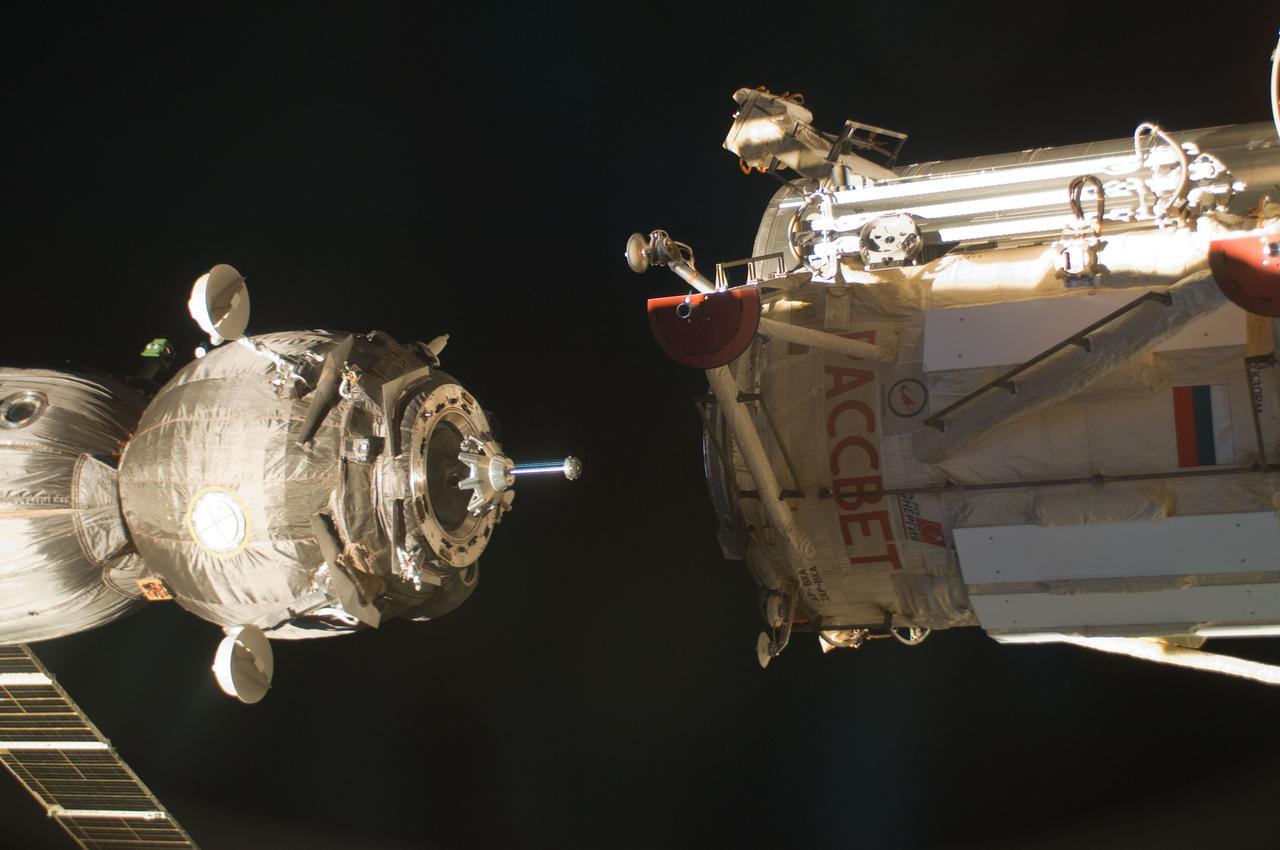
ISS030-E-015603 (23 Dec. 2011) --- With the three Expedition 30/31 crew members aboard, the Soyuz TMA-03M spacecraft (left) eases toward its docking with the Russian-built Mini-Research Module 1 (MRM-1), also known as Rassvet, Russian for "dawn." The docking, which once more enables six astronauts and cosmonauts to work together aboard the Earth-orbiting International Space Station, took place at 9:19 a.m. (CST) on Dec. 23, 2011.
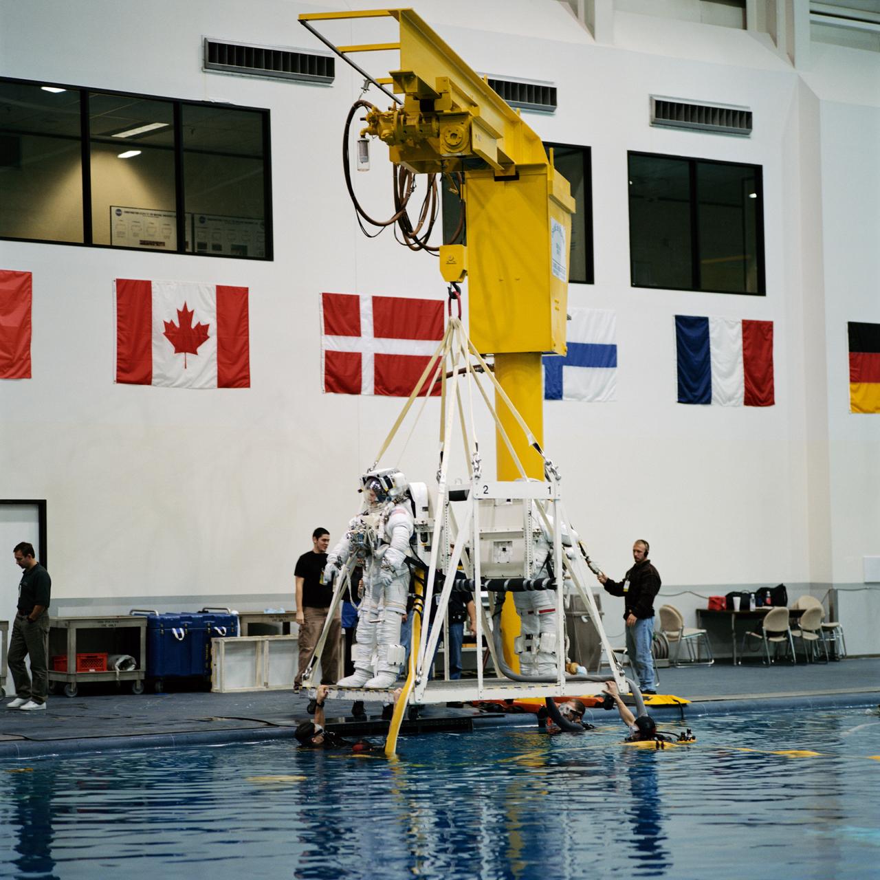
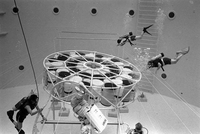
JSC2000-07400 (1 Dec. 2000) --- Both attired in training versions of the Extravehicular Mobility Unit (EMU) spacesuit, astronauts Scott E. Parazynski (left) and Chris A. Hadfield stand on a platform that will ease the two STS-100 mission specialists into a giant pool of water at the Neutral Buoyancy Laboratory (NBL). Minutes later, the two were in a neutrally buoyant state beneath the surface rehearsing spacewalk duties scheduled for next year's visit to the International Space Station (ISS). Hadfield represents the Canadian Space Agency (CSA).
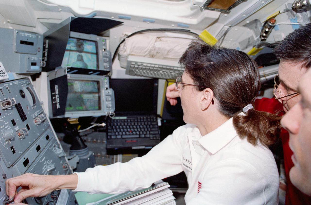
STS088-341-024 (4-15 Dec. 1998) --- Astronaut Nancy J. Currie, mission specialist, operates the controls of Endeavour's remote manipulator system (RMS) arm to ease the Russian-built Zarya module onto the U.S.-built Unity connecting module in the shuttle's cargo bay. At right are astronauts Robert D. Cabana, mission commander; and James H. Newman, mission specialist, partially out of frame.
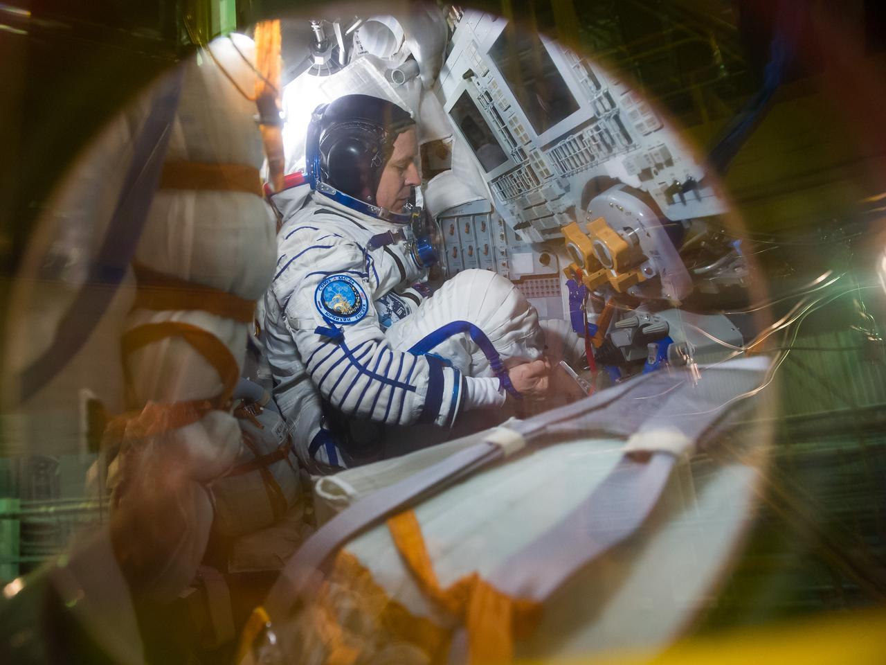
jsc2017e040290 (April 6, 2017) --- In the Integration Building at the Baikonur Cosmodrome in Kazakhstan, Expedition 51 crewmember Jack Fischer of NASA eases into his seat in the Soyuz MS-04 spacecraft April 6 as part of pre-launch training preparations. Fischer and Fyodor Yurchikhin of the Russian Federal Space Agency (Roscosmos) will launch April 20 on the Soyuz MS-04 spacecraft for a four and a half month mission on the International Space Station. NASA/Gagarin Cosmonaut Training Center/Andrey Shelepin
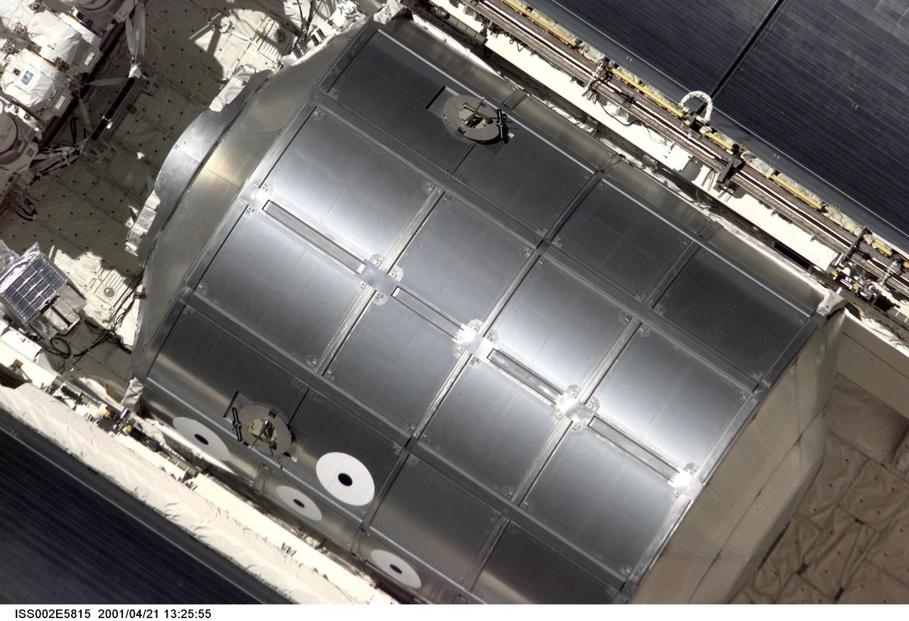
ISS002-E-5815 (21 April 2001) --- The Raffaello Multi-Purpose Logistics Module (MPLM), built by the Italian Space Agency (ASI), sits in its berthed position in the cargo bay of the Space Shuttle Endeavour as the STS-100 crew eases the vehicle close to the International Space Station (ISS) for docking. The image was recorded with a digital still camera by one of the Expedition Two crew members aboard the Station.

This view of deforestation in Rondonia, far western Brazil, (10.0S, 63.0W) is part of an agricultural resettlement project which ultimately covers an area about 80% the size of France. The patterns of deforestation in this part of the Amazon River Basin are usually aligned adjacent to highways, secondary roads, and streams for ease of access and transportation. Compare this view with the earlier 51G-37-062 for a comparison of deforestation in the region.
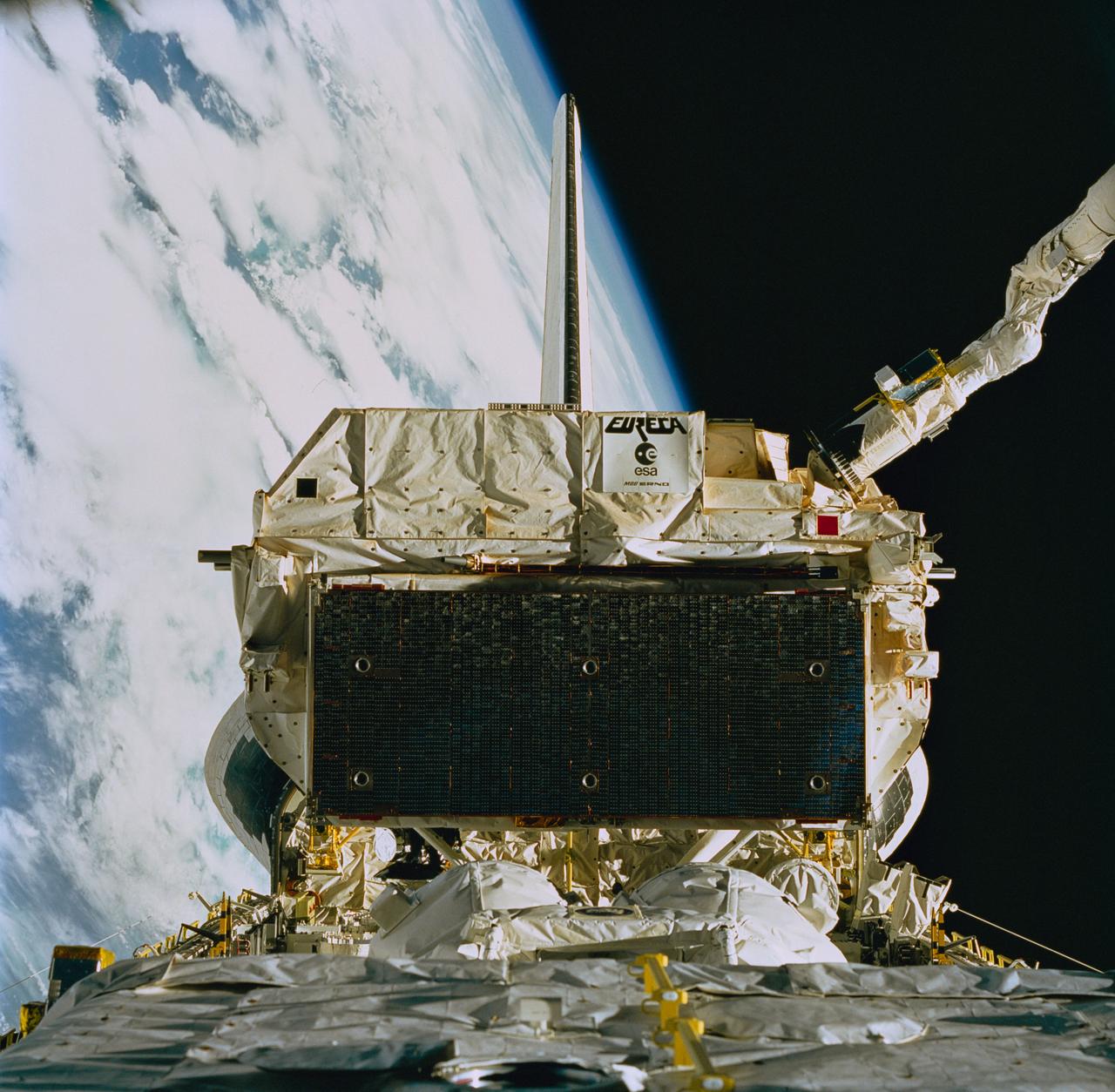
STS057-84-000AD (24 June 1993) --- The recently "captured" European Retrievable Carrier (EURECA) was recorded on 70mm film as it was berthed in the Space Shuttle Endeavour's aft cargo bay, assisted by the Canadian-built Remote Manipulator System (RMS), partially visible in upper right. Moments later the RMS eased EURECA into its stowage area between Endeavour's aft cargo bay firewall and the SpaceHab module (partially visible in foreground).
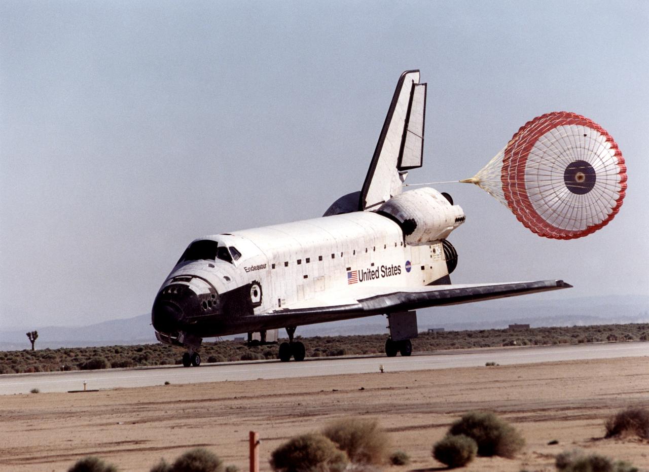
STS100-S-020 (1 May 2001) --- The drag chute on the space shuttle Endeavour helps to slow the vehicle down as it eases to the completion of the STS-100 mission on a desert runway at Edwards Air Force Base in California. Touchdown occurred at 9:11 a.m. (PDT), May 1, 2001. Onboard the shuttle were six NASA astronauts and a cosmonaut representing Rosaviakosmos. Photo credit: NASA
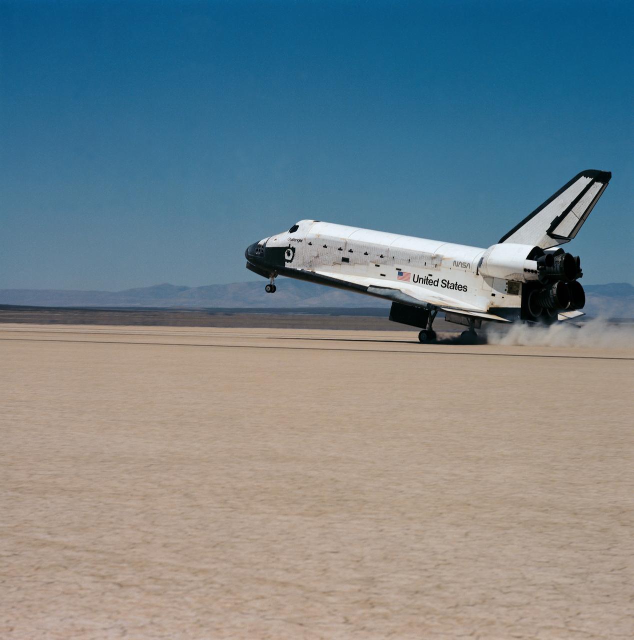
51F-S-161 (6 Aug 1985) --- The Space Shuttle Challenger, with its seven member crew and battery of scientific experiments aboard, eases its rear landing gear onto the dry lake bed at Edwards Air Force Base in California. Onboard for the eight-day mission were C. Gordon Fullerton, Roy D. Bridges Jr., F. Story Musgrave, Karl J. Henize, Anthony W. England, Loren W. Acton and John-David Bartoe.
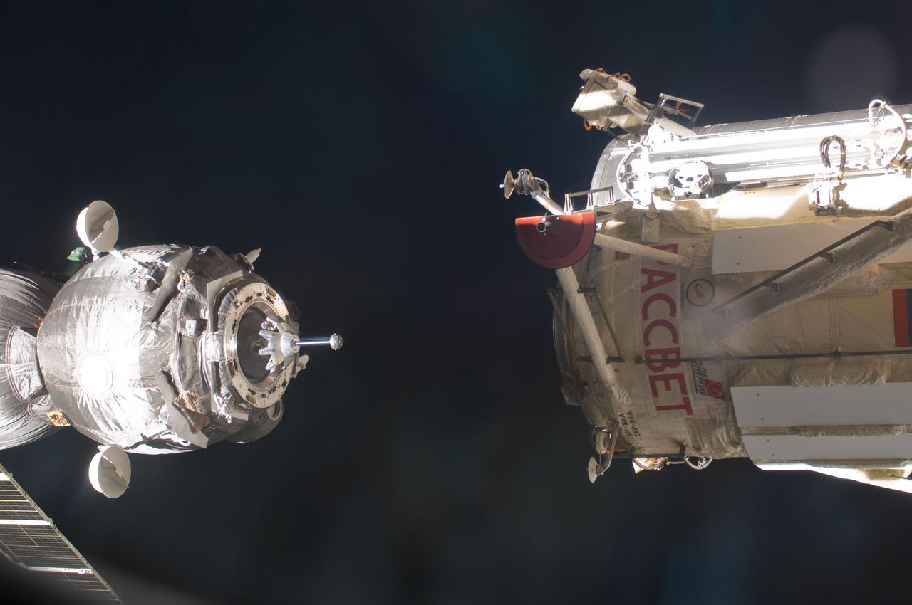
ISS030-E-015599 (23 Dec. 2011) --- With the three Expedition 30/31 crew members aboard, the Soyuz TMA-03M spacecraft (left) eases toward its docking with the Russian-built Mini-Research Module 1 (MRM-1), also known as Rassvet, Russian for "dawn." The docking, which once more enables six astronauts and cosmonauts to work together aboard the Earth-orbiting International Space Station, took place at 9:19 a.m. (CST) on Dec. 23, 2011.
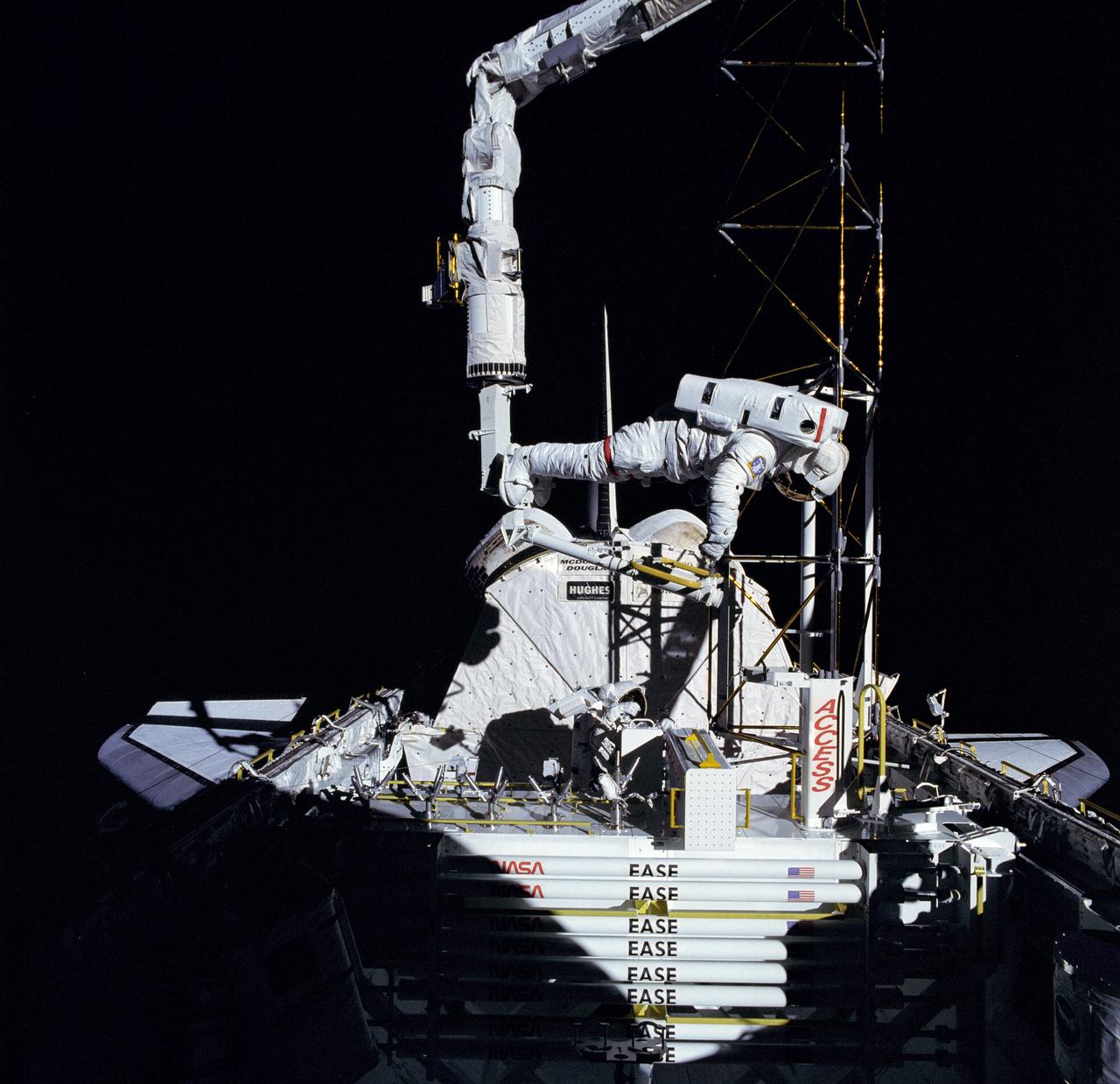
The crew assigned to the STS-61B mission included Bryan D. O’Conner, pilot; Brewster H. Shaw, commander; Charles D. Walker, payload specialist; mission specialists Jerry L. Ross, Mary L. Cleave, and Sherwood C. Spring; and Rodolpho Neri Vela, payload specialist. Launched aboard the Space Shuttle Atlantis November 28, 1985 at 7:29:00 pm (EST), the STS-61B mission’s primary payload included three communications satellites: MORELOS-B (Mexico); AUSSAT-2 (Australia); and SATCOM KU-2 (RCA Americom). Two experiments were conducted to test assembling erectable structures in space: EASE (Experimental Assembly of Structures in Extravehicular Activity), and ACCESS (Assembly Concept for Construction of Erectable Space Structure). In a joint venture between NASA/Langley Research Center in Hampton, Virginia and the Marshall Space Flight Center (MSFC), EASE and ACCESS were developed and demonstrated at MSFC's Neutral Buoyancy Simulator (NBS). The primary objective of this experiment was to test the structural assembly concepts for suitability as the framework for larger space structures and to identify ways to improve the productivity of space construction. In this STS-61B onboard photo, astronaut Ross was working on the ACCESS experiment during an Extravehicular Activity (EVA).
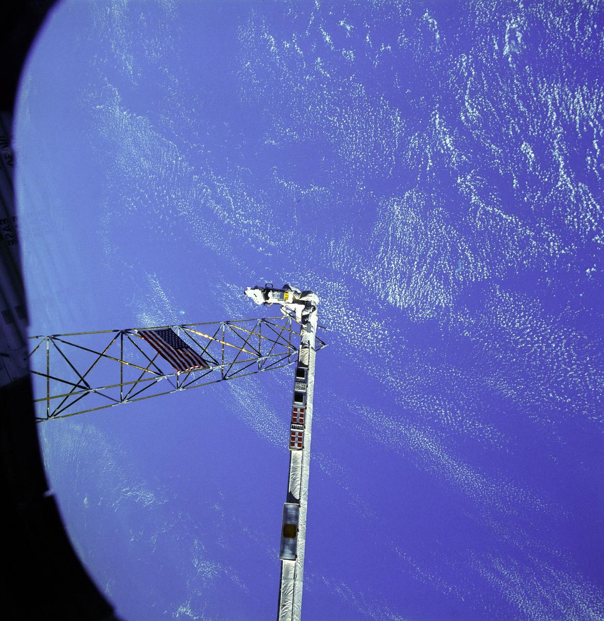
The crew assigned to the STS-61B mission included Bryan D. O’Conner, pilot; Brewster H. Shaw, commander; Charles D. Walker, payload specialist; mission specialists Jerry L. Ross, Mary L. Cleave, and Sherwood C. Spring; and Rodolpho Neri Vela, payload specialist. Launched aboard the Space Shuttle Atlantis November 28, 1985 at 7:29:00 pm (EST), the STS-61B mission’s primary payload included three communications satellites: MORELOS-B (Mexico); AUSSAT-2 (Australia); and SATCOM KU-2 (RCA Americom). Two experiments were conducted to test assembling erectable structures in space: EASE (Experimental Assembly of Structures in Extravehicular Activity), and ACCESS (Assembly Concept for Construction of Erectable Space Structure). In a joint venture between NASA/Langley Research Center in Hampton, Virginia, and the Marshall Space Flight Center (MSFC), EASE and ACCESS were developed and demonstrated at MSFC's Neutral Buoyancy Simulator (NBS). In this STS-61B onboard photo, astronaut Ross works on ACCESS high above the orbiter. The primary objective of these experiments was to test the structural assembly concepts for suitability as the framework for larger space structures and to identify ways to improve the productivity of space construction.
The crew assigned to the STS-61B mission included Bryan D. O’Conner, pilot; Brewster H. Shaw, commander; Charles D. Walker, payload specialist; mission specialists Jerry L. Ross, Mary L. Cleave, and Sherwood C. Spring; and Rodolpho Neri Vela, payload specialist. Launched aboard the Space Shuttle Atlantis November 28, 1985 at 7:29:00 pm (EST), the STS-61B mission’s primary payload included three communications satellites: MORELOS-B (Mexico); AUSSAT-2 (Australia); and SATCOM KU-2 (RCA Americom). Two experiments were conducted to test assembling erectable structures in space: EASE (Experimental Assembly of Structures in Extravehicular Activity), and ACCESS (Assembly Concept for Construction of Erectable Space Structure). In a joint venture between NASA/Langley Research Center in Hampton, Virginia and the Marshall Space Flight Center (MSFC), EASE and ACCESS were developed and demonstrated at MSFC's Neutral Buoyancy Simulator (NBS). In this STS-61B onboard photo astronaut Ross, located on the Manipulator Foot Restraint (MFR) over the cargo bay, erects ACCESS. The primary objective of this experiment was to test the structural assembly concepts for suitability as the framework for larger space structures and to identify ways to improve the productivity of space construction.
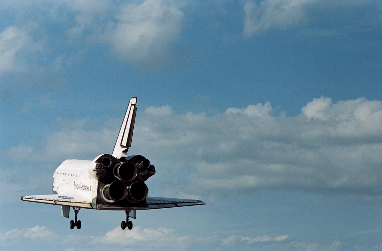
STS110-S-039 (19 April 2002) --- The Space Shuttle Atlantis heads for touchdown on the runway at the KSC landing facility to complete a nearly 11-day journey. Astronaut Michael J. Bloomfield, mission commander, eased Atlantis to a textbook landing on runway 3-3 at the Florida spaceport at 12:27 p.m. (EDT), April 19, 2002, under clear skies and light winds. The landing completed a 4.5-million-mile mission that saw successful delivery and installation of the centerpiece of the International Space Station’s main truss and the inaugural run of the first space railcar, the Mobile Transporter.
STS110-S-057 (19 April 2002) --- The Space Shuttle Atlantis heads for touchdown on the runway at the KSC landing facility to complete the nearly 11-day STS-110 journey. Astronaut Michael J. Bloomfield, mission commander, eased Atlantis to a textbook landing on runway 3-3 at the Florida spaceport at 12:27 p.m. (EDT), April 19, 2002, under clear skies and light winds. The landing completed a 4.5-million-mile mission that saw successful delivery and installation of the centerpiece of the International Space Station?s main truss and the inaugural run of the first space railcar, the Mobile Transporter.
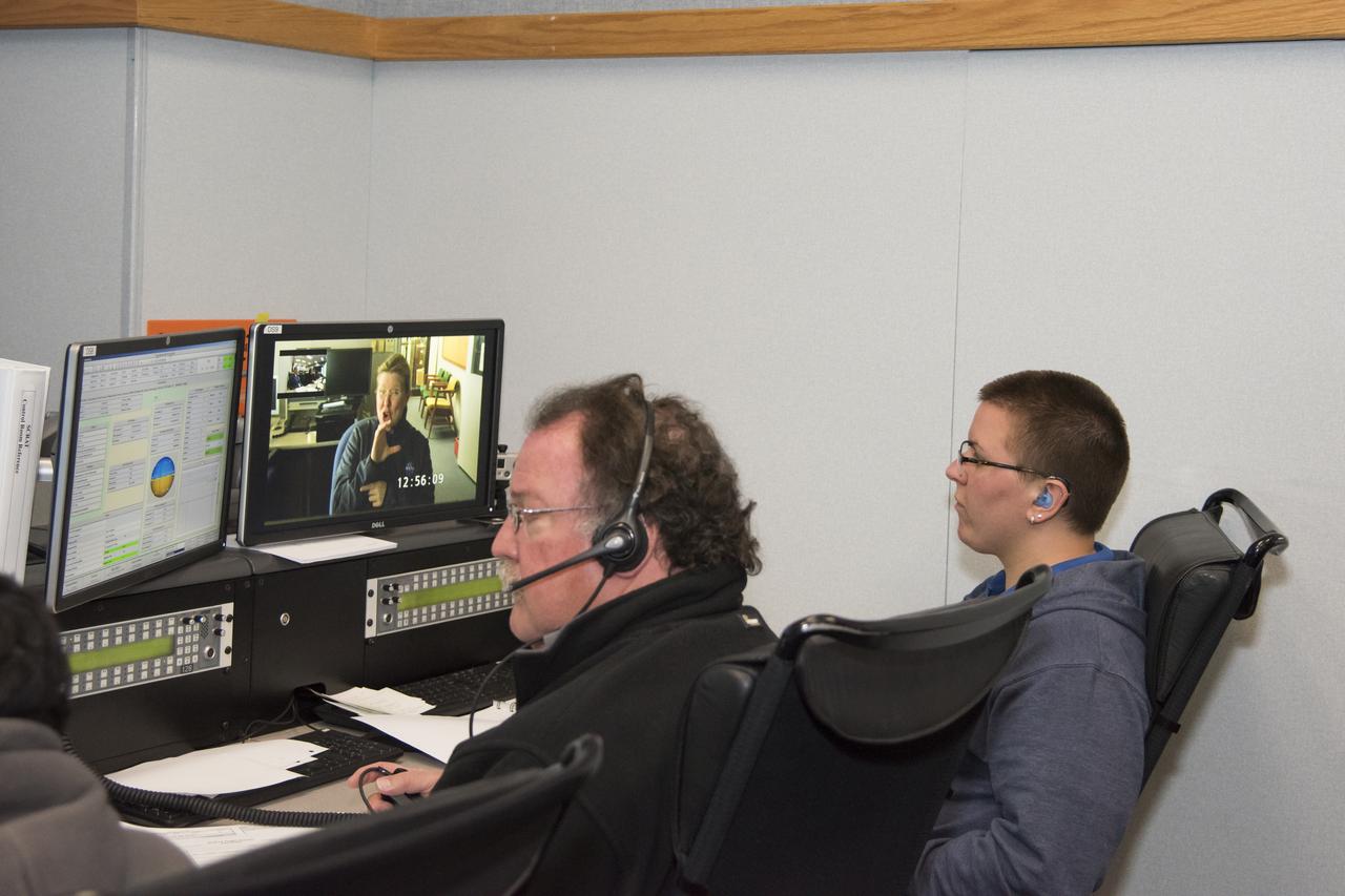
Johanna Lucht, observing data from the Mission Control Center at NASA’s Armstrong Flight Research Center in California, received flight communications from an interpreter, seen on Lucht’s monitor, through American Sign Language. Two-way visual communication was established between Lucht and the interpreter, located at NASA’s Langley Research Center in Virginia, for the flight. Interpreting technical terminology often requires cooperation to develop specific signs to ease communication. Using a familiar interpreter who is adept or practiced in the technical terminology of a NASA flight was beneficial, Lucht says.
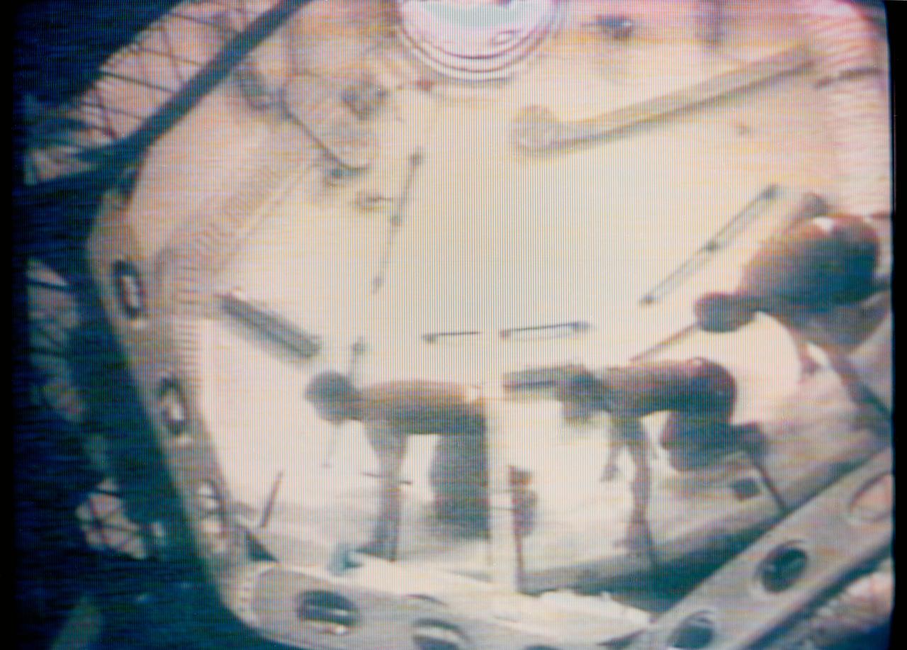
S73-27262 (1 June 1973) --- The three Skylab 2 crewmen give a demonstration on the effects of weightlessness in the Orbital Workshop of the Skylab 1 and 2 space station cluster in Earth orbit, as seen in this reproduction taken from a color television transmission made by a TV camera aboard the space station. Astronauts Charles Conrad Jr., Joseph P. Kerwin and Paul J. Weitz are crouched in a fast-start stance to race around the dome area of the OWS forward compartment. The astronauts had ease of motion and good maneuverability in the zero-gravity of space. Photo credit: NASA
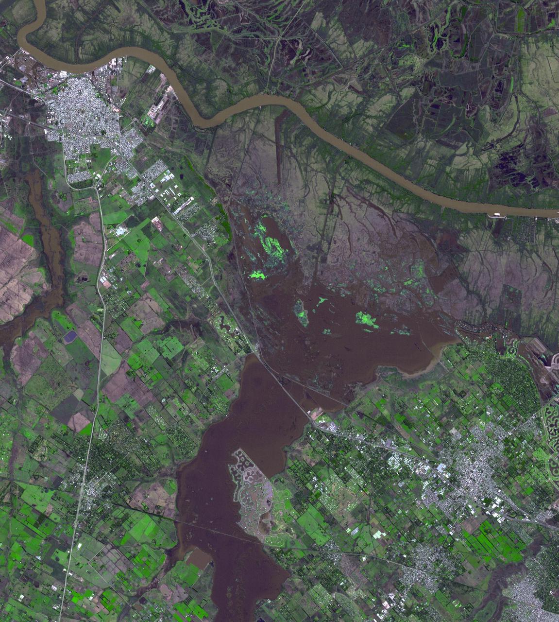
Northwest of Buenos Aires, Argentina, seven straight days of torrential rains of up to 16 inches 40 centimeters in August 2015 resulted in flooding between the cities of Escobar and Campana as seen by NASA Terra spacecraft. The flooding has since eased, allowing some evacuated residents of the 39 affected municipalities to return to their homes. The flooding was captured in this satellite image acquired Aug. 16, 2015, by the Advanced Spaceborne Thermal Emission and Reflection Radiometer (ASTER) instrument on NASA's Terra spacecraft. The image covers an area of 16.7 by 17.4 miles (26.9 by 28 kilometers), and is located at 34.2 degrees south, 58.6 degrees west. http://photojournal.jpl.nasa.gov/catalog/PIA19871
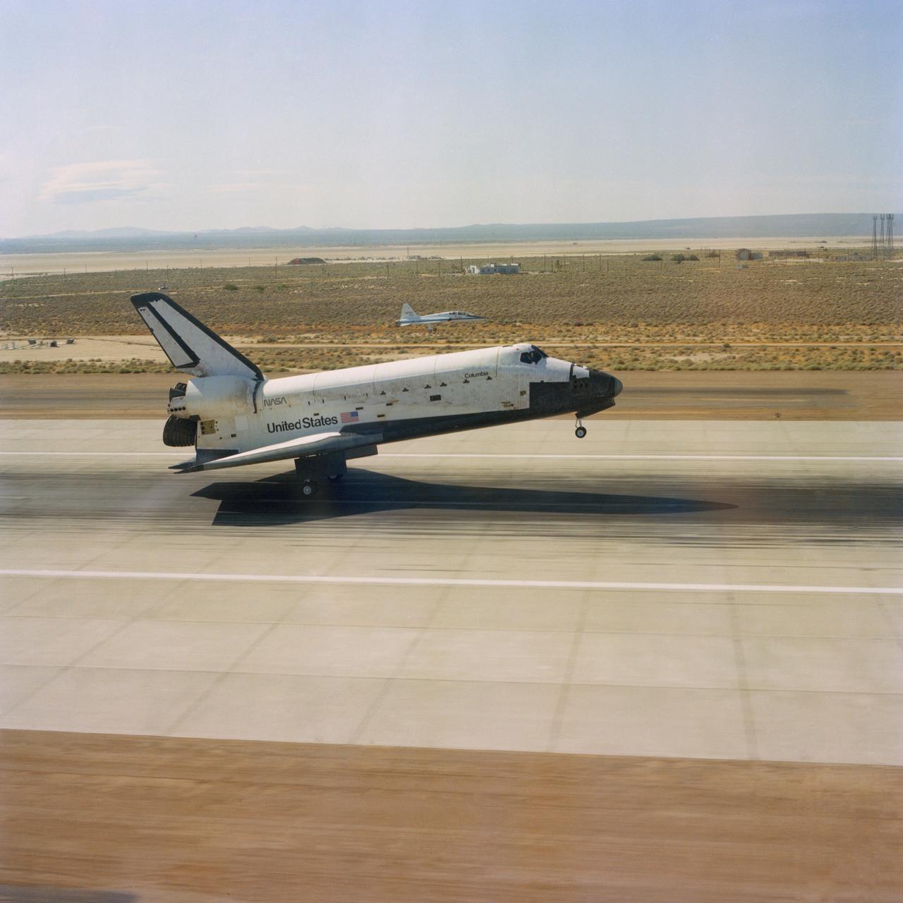
S82-33420 (4 July 1982) --- The aft wheels of the space shuttle Columbia ease down on the runway at Edwards Air Force Base (AFB) today to successfully complete a week-long spaceflight for astronauts Thomas K. Mattingly II, and Henry W. Hartsfield Jr. A T-38 aircraft serves as a chase plane (just above center of photo) in the background. Not long after this photograph was made and the crew had egressed their craft, President Ronald Reagan addressed a giant crowd on hand at Edwards AFB for a special kind of July 4 celebration. Photo credit: NASA
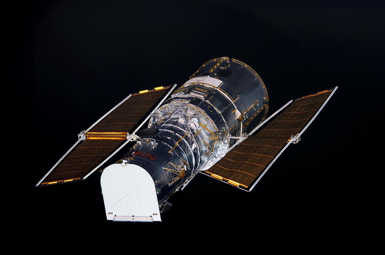
STS109-E-5014 (3 March 2002) --- The Hubble Space Telescope is backdropped against black space as the Space Shuttle Columbia, with a crew of seven astronauts on board, eases closer and closer in order to latch its 50-foot-long robotic arm onto a fixture on the giant telescope. As Columbia flew 350 miles above the Pacific Ocean Southwest of Mexico, with astronaut Nancy J. Currie, mission specialist, in control of the arm and astronaut Scott D. Altman, mission commander, at the controls of the shuttle, the crew went on to capture the Hubble. The image was one of a series recorded with a digital still camera.
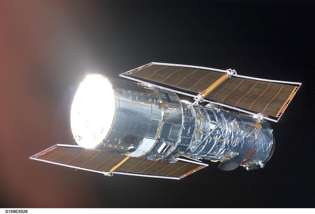
STS109-E-5026 (3 March 2002) --- The Hubble Space Telescope is backdropped against black space as the Space Shuttle Columbia, with a crew of seven astronauts on board, eases closer and closer in order to latch its 50-foot-long robotic arm onto a fixture on the giant telescope. As Columbia flew 350 miles above the Pacific Ocean Southwest of Mexico, with astronaut Nancy J. Currie, mission specialist, in control of the arm and astronaut Scott D. Altman, mission commander, at the controls of the shuttle, the crew went on to capture the Hubble. The image was one of a series recorded with a digital still camera.
STS113-S-041 (7 December 2002) --- The main landing gear of Space Shuttle Endeavour touches down on runway 33 at the KSC landing facility, completing the nearly 14-day STS-113 mission to the International Space Station (ISS). Astronaut James D. Wetherbee, mission commander, eased Endeavour to a textbook landing on runway 33 at the Florida spaceport at 2:37 p.m. (EST) on December 7, 2002. The landing completed a 5.74-million mile mission that saw successful delivery and installation of the Port One (P1) truss on the orbital outpost.
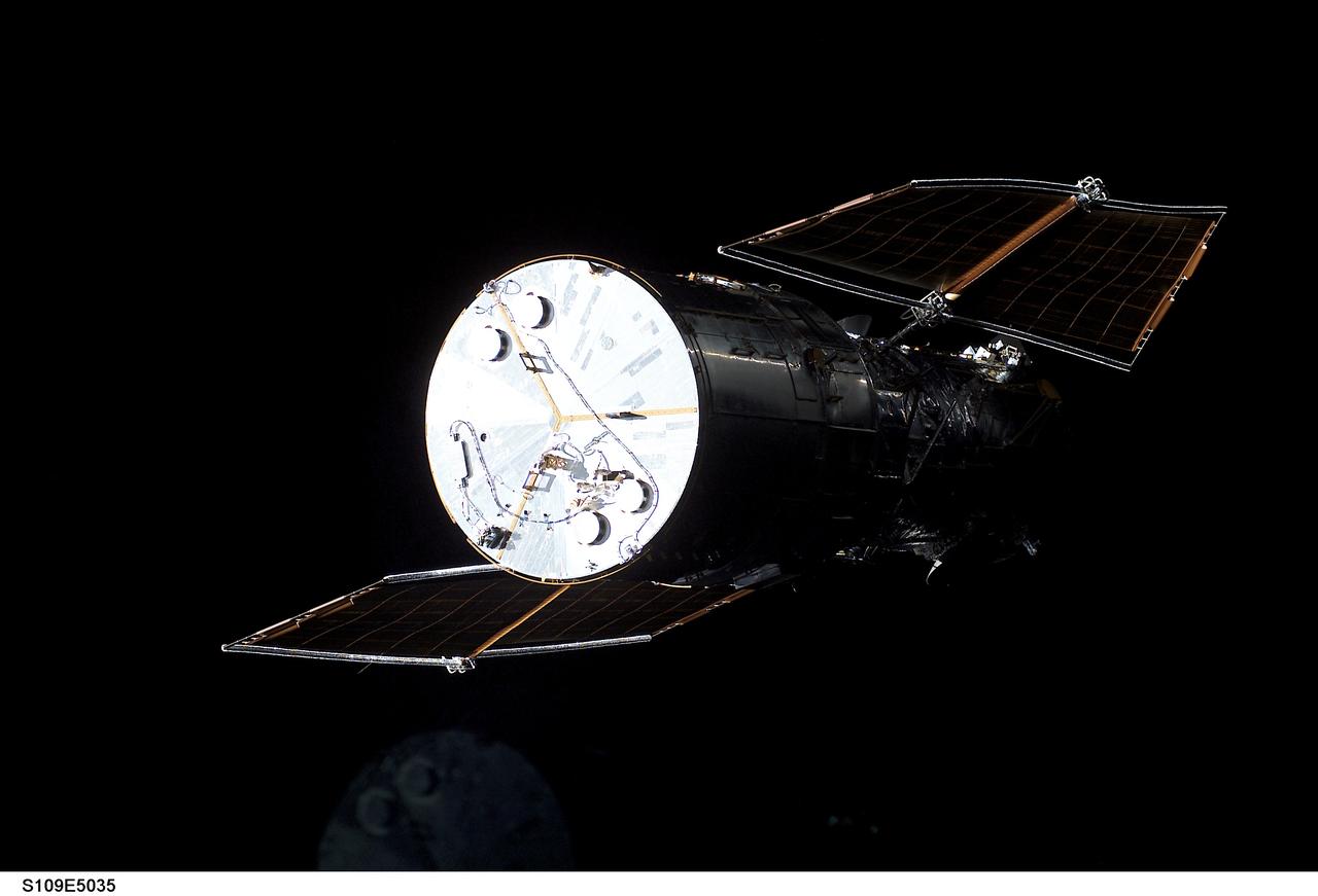
STS109-E-5035 (3 March 2002) --- The Hubble Space Telescope is visible against black space, primarily because its bright metallic disk-shaped base and the frame of its solar panels, as the Space Shuttle Columbia eases closer and closer in order to latch its 50-foot-long robotic arm onto a fixture on the giant telescope. As Columbia flew 350 miles above the Pacific Ocean Southwest of Mexico, with astronaut Nancy J. Currie, mission specialist, in control of the arm and astronaut Scott D. Altman, mission commander, at the controls of the shuttle, the seven-member crew went on to capture the Hubble. The image was one of a series recorded with a digital still camera.
STS113-S-043 (7 December 2002) --- The drag chute on the Space Shuttle Endeavour deploys to slow down the spacecraft during landing on runway 33 at the KSC landing facility, completing the nearly 14-day STS-113 mission to the International Space Station (ISS). Astronaut James D. Wetherbee, mission commander, eased Endeavour to a textbook landing on runway 33 at the Florida spaceport at 2:37 p.m. (EST) on December 7, 2002. The landing completed a 5.74-million mile mission that saw successful delivery and installation of the Port One (P1) truss on the orbital outpost.

STS110-S-039 (19 April 2002) --- The Space Shuttle Atlantis heads for touchdown on the runway at the KSC landing facility to complete a nearly 11-day journey. Astronaut Michael J. Bloomfield, mission commander, eased Atlantis to a textbook landing on runway 3-3 at the Florida spaceport at 12:27 p.m. (EDT), April 19, 2002, under clear skies and light winds. The landing completed a 4.5-million-mile mission that saw successful delivery and installation of the centerpiece of the International Space Station’s main truss and the inaugural run of the first space railcar, the Mobile Transporter.
STS113-S-044 (7 December 2002) --- The Space Shuttle Endeavour’s main landing gear is just about to touch down on runway 33 at the Shuttle Landing Facility at the Kennedy Space Center (KSC), completing the nearly 14-day STS-113 mission to the International Space Station (ISS). Astronaut James D. Wetherbee, mission commander, eased Endeavour to a textbook landing at 2:37 p.m. (EST) on December 7, 2002. The landing completed a 5.74-million mile mission that saw successful delivery and installation of the Port One (P1) truss on the orbital outpost.

During pre-pack and fit check, STS-92 Commander Brian Duffy tests his launch and entry suit for comfort and ease while sitting. This mission will be Duffy’s fourth Shuttle flight. He and the rest of the crew are at KSC for Terminal Countdown Demonstration Test activities. The TCDT provides emergency egress training, simulated countdown exercises and opportunities to inspect the mission payload. STS-92 is scheduled to launch Oct. 5 at 9:38 p.m. EDT from Launch Pad 39A on the fifth flight to the International Space Station. It will carry two elements of the Space Station, the Integrated Truss Structure Z1 and the third Pressurized Mating Adapter. The mission is also the 100th flight in the Shuttle program
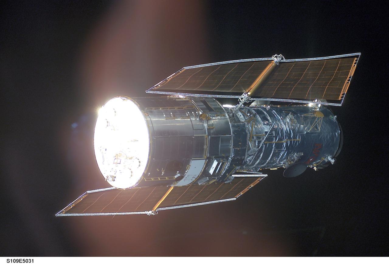
STS109-E-5031 (3 March 2002) --- The Hubble Space Telescope is backdropped against black space as the Space Shuttle Columbia, with a crew of seven astronauts on board, eases closer and closer in order to latch its 50-foot-long robotic arm onto a fixture on the giant telescope. As Columbia flew 350 miles above the Pacific Ocean Southwest of Mexico, with astronaut Nancy J. Currie, mission specialist, in control of the arm and astronaut Scott D. Altman, mission commander, at the controls of the shuttle, the crew went on to capture the Hubble. The image was one of a series recorded with a digital still camera.
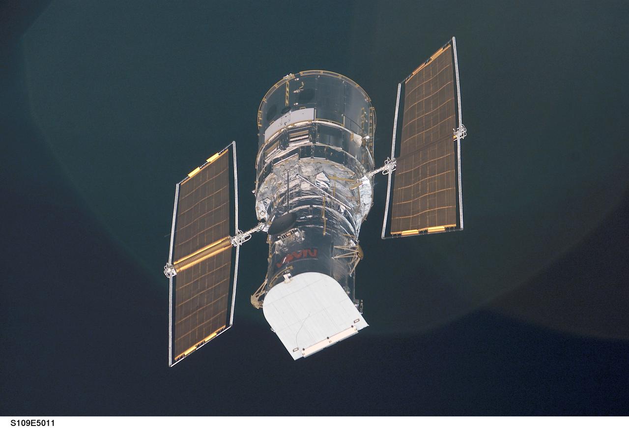
STS109-E-5011 (3 March 2002) --- The Hubble Space Telescope is backdropped against black space as the Space Shuttle Columbia, with a crew of seven astronauts on board, eases closer and closer in order to latch its 50-foot-long robotic arm onto a fixture on the giant telescope. As Columbia flew 350 miles above the Pacific Ocean Southwest of Mexico, with astronaut Nancy J. Currie, mission specialist, in control of the arm and astronaut Scott D. Altman, mission commander, at the controls of the shuttle, the crew went on to capture the Hubble. The image was one of a series recorded with a digital still camera.
STS113-S-021 (7 December 2002) --- The main landing gear of Space Shuttle Endeavour touches down on runway 33 at the KSC landing facility, completing the nearly 14-day STS-113 mission to the International Space Station (ISS). Astronaut James D. Wetherbee, mission commander, eased Endeavour to a textbook landing on runway 33 at the Florida spaceport at 2:37 p.m. (EST) on December 7, 2002. The landing completed a 5.74-million mile mission that saw successful delivery and installation of the Port One (P1) truss on the orbital outpost.
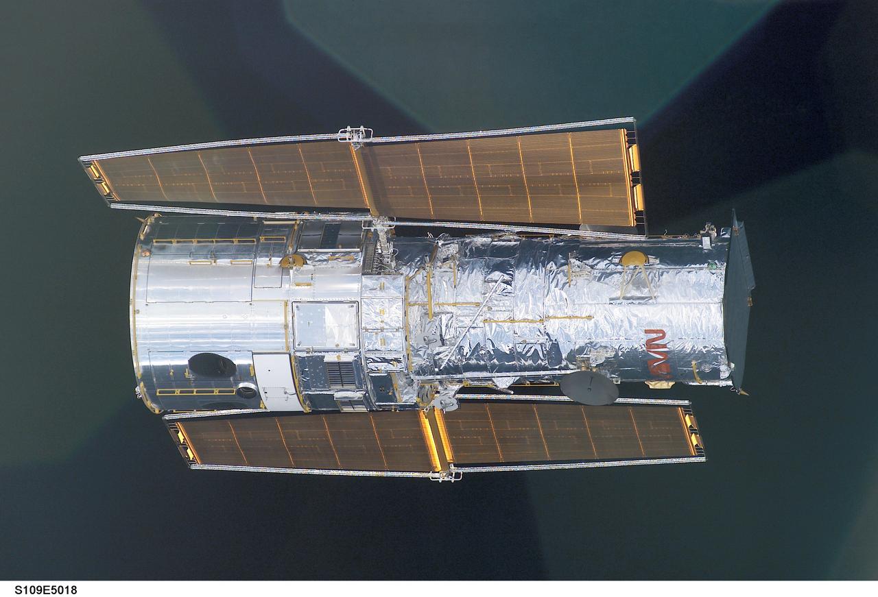
STS109-E-5018 (3 March 2002) --- The Hubble Space Telescope is backdropped against black space as the Space Shuttle Columbia, with a crew of seven stronauts on board, eases closer and closer in order to latch its 50-foot-long robotic arm onto a fixture on the giant telescope. As Columbia flew 350 miles above the Pacific Ocean Southwest of Mexico, with astronaut Nancy J. Currie, mission specialist, in control of the arm and astronaut Scott D. Altman, mission commander, at the controls of the shuttle, the crew went on to capture the Hubble. The image was one of a series recorded with a digital still camera.
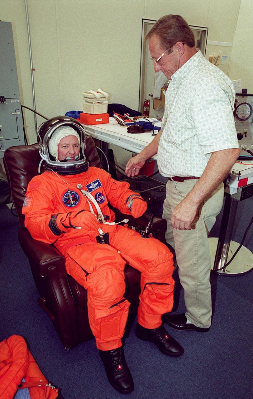
During pre-pack and fit check, STS-92 Commander Brian Duffy tests his launch and entry suit for comfort and ease while sitting. This mission will be Duffy’s fourth Shuttle flight. He and the rest of the crew are at KSC for Terminal Countdown Demonstration Test activities. The TCDT provides emergency egress training, simulated countdown exercises and opportunities to inspect the mission payload. STS-92 is scheduled to launch Oct. 5 at 9:38 p.m. EDT from Launch Pad 39A on the fifth flight to the International Space Station. It will carry two elements of the Space Station, the Integrated Truss Structure Z1 and the third Pressurized Mating Adapter. The mission is also the 100th flight in the Shuttle program
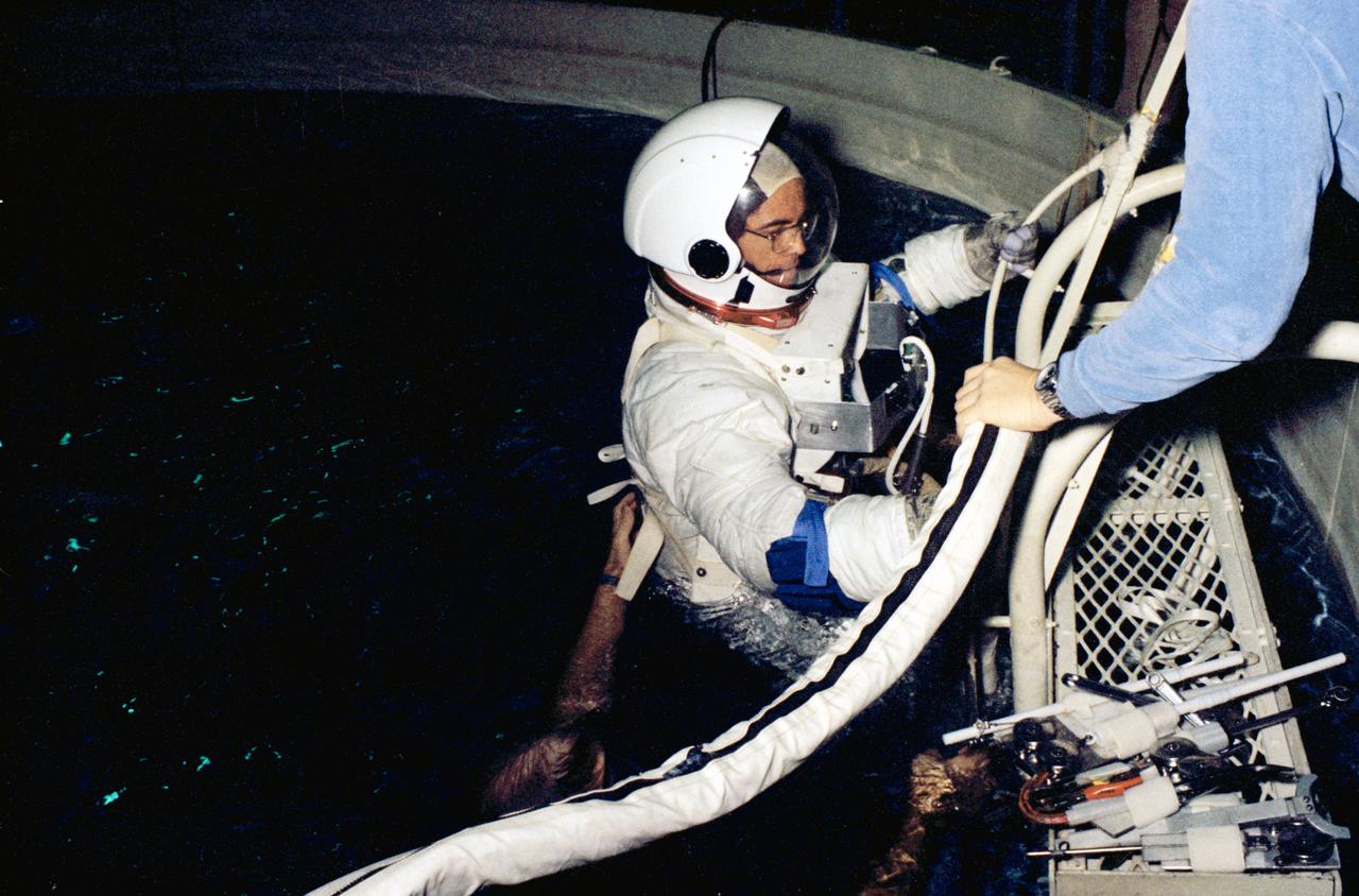
S79-25014 (13 Dec. 1978) --- Astronaut Robert L. Crippen, pilot of the first space shuttle orbital flight test (STS-1), eases into a water immersion facility (WIF) during a training session in the Johnson Space Center?s training and test facility (Bldg. 260). The WIF affords one of two ways to simulate the feeling of weightlessness experienced during space extravehicular activity (EVA), the other being inside aircraft flying a parabolic curve. Crippen will be joined by astronaut John W. Young, commander for the STS-1 flight. Photo credit: NASA
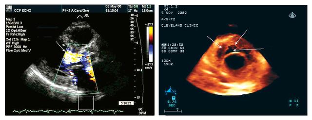
Echocardiography uses sound waves to image the heart and other organs. Developing a compact version of the latest technology improved the ease of monitoring crew member health, a critical task during long space flights. NASA researchers plan to adapt the three-dimensional (3-D) echocardiogram for space flight. The two-dimensional (2-D) echocardiogram utilized in orbit on the International Space Station (ISS) was effective, but difficult to use with precision. A heart image from a 2-D echocardiogram (left) is of a better quality than that from a 3-D device (right), but the 3-D imaging procedure is more user-friendly.
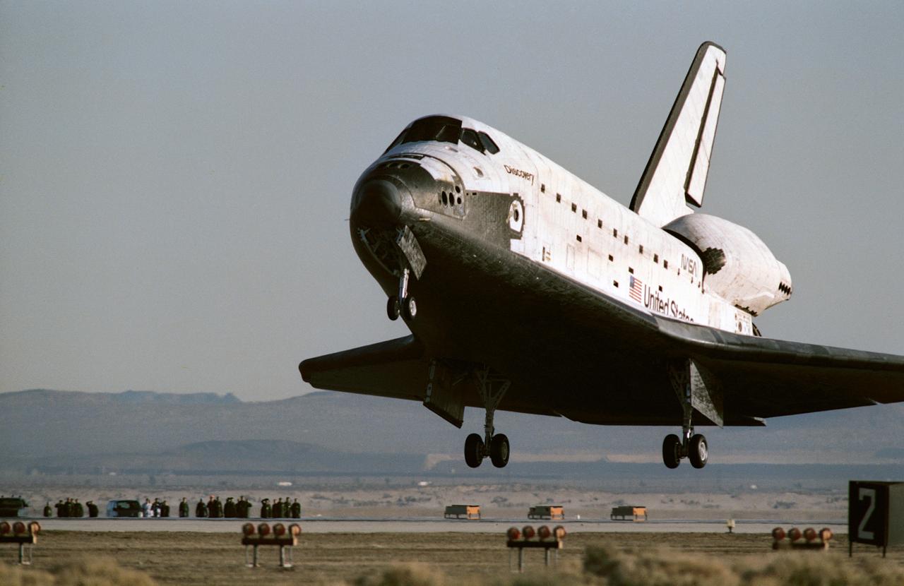
STS042-S-093 (30 Jan 1992) --- Space Shuttle Discovery is just about to ease down its main gear on Runway 22 at Edwards Air Force Base in southern California. Main gear touchdown occurred at 8:07:18 a.m. (PST), Jan. 30, 1992. The successful landing completed an eight-day mission for five NASA astronauts and two payload specialists supporting the first International Microgravity Laboratory (IML-1) mission. Onboard were astronauts Ronald J. Grabe, mission commander; Stephen S. Oswald, pilot; Norman E. Thagard, payload commander; David C. Hilmers and William F. Readdy, both mission specialists; and payload specialists Roberta L. Bondar of Canada and Ulf Merbold, representing the European Space Agency (ESA).
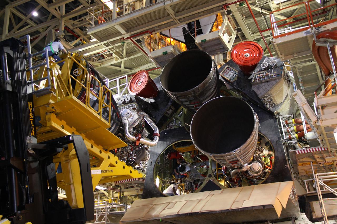
CAPE CANAVERAL, Fla. - In Orbiter Processing Facility Bay 3 at NASA's Kennedy Space Center in Florida, a United Space Alliance worker eases a space shuttle main engine toward shuttle Discovery during installation of the shuttle's engines to support the STS-131 mission to the International Space Station. The seven-member STS-131 crew will deliver a Multi-Purpose Logistics Module filled with resupply stowage platforms and racks to be transferred to locations around the station. Three spacewalks will include work to attach a spare ammonia tank assembly to the station's exterior and return a European experiment from outside the station's Columbus module. Discovery's launch, targeted for March 18, 2010, will initiate the 33rd shuttle mission to the station. For information on the STS-131 mission and crew, visit http://www.nasa.gov/mission_pages/shuttle/shuttlemissions/sts131/index.html. Photo credit: NASA/Jack Pfaller

The first stage of a Boeing Delta rocket is eased into a vertical position to be lifted up the gantry on Launch Pad 17-A, Cape Canaveral Air Force Station. The rocket will carry the 2001 Mars Odyssey Orbiter, scheduled for launch April 7, 2001. Mars Odyssey contains three science instruments: THEMIS, the Gamma Ray Spectrometer (GRS), and the Mars Radiation Environment Experiment (MARIE). THEMIS will map the mineralogy and morphology of the Martian surface using a high-resolution camera and a thermal infrared imaging spectrometer. The GRS will achieve global mapping of the elemental composition of the surface and determine the abundance of hydrogen in the shallow subsurface. The MARIE will characterize aspects of the near-space radiation environment with regards to the radiation-related risk to human explorers

STS040-211-019 (5-14 June 1991) --- Astride the bicycle ergometer, astronaut Rhea Seddon, mission specialist, breathes into the cardiovascular re-breathing unit during the exercise phase of an experiment. The investigation, In-flight Study of Cardiovascular Deconditioning (Experiment 066), was developed by Dr. Leon E. Farhi of the State University of New York in Buffalo. It focuses on the deconditioning of the heart and lungs and changes in cardiopulmonary function that occur upon return to Earth. By using non-invasive techniques of prolonged expiration and re-breathing, investigators can determine the amount of blood pumped out of the heart (cardiac output), the ease with which blood flows through all the vessels (total peripheral resistance), oxygen used and carbon dioxide released by the body, and lung function and volume changes. Measurements are made both while crew members are resting and while they pedal the exercise bicycle, as Dr. Seddon is doing here. This scene was photographed with a 35mm camera.
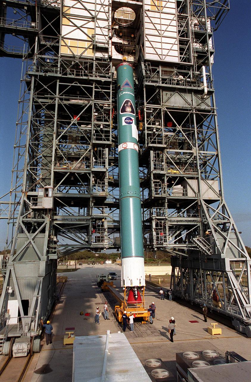
The first stage of a Boeing Delta rocket is eased into a vertical position to be lifted up the gantry on Launch Pad 17-A, Cape Canaveral Air Force Station. The rocket will carry the 2001 Mars Odyssey Orbiter, scheduled for launch April 7, 2001. Mars Odyssey contains three science instruments: THEMIS, the Gamma Ray Spectrometer (GRS), and the Mars Radiation Environment Experiment (MARIE). THEMIS will map the mineralogy and morphology of the Martian surface using a high-resolution camera and a thermal infrared imaging spectrometer. The GRS will achieve global mapping of the elemental composition of the surface and determine the abundance of hydrogen in the shallow subsurface. The MARIE will characterize aspects of the near-space radiation environment with regards to the radiation-related risk to human explorers
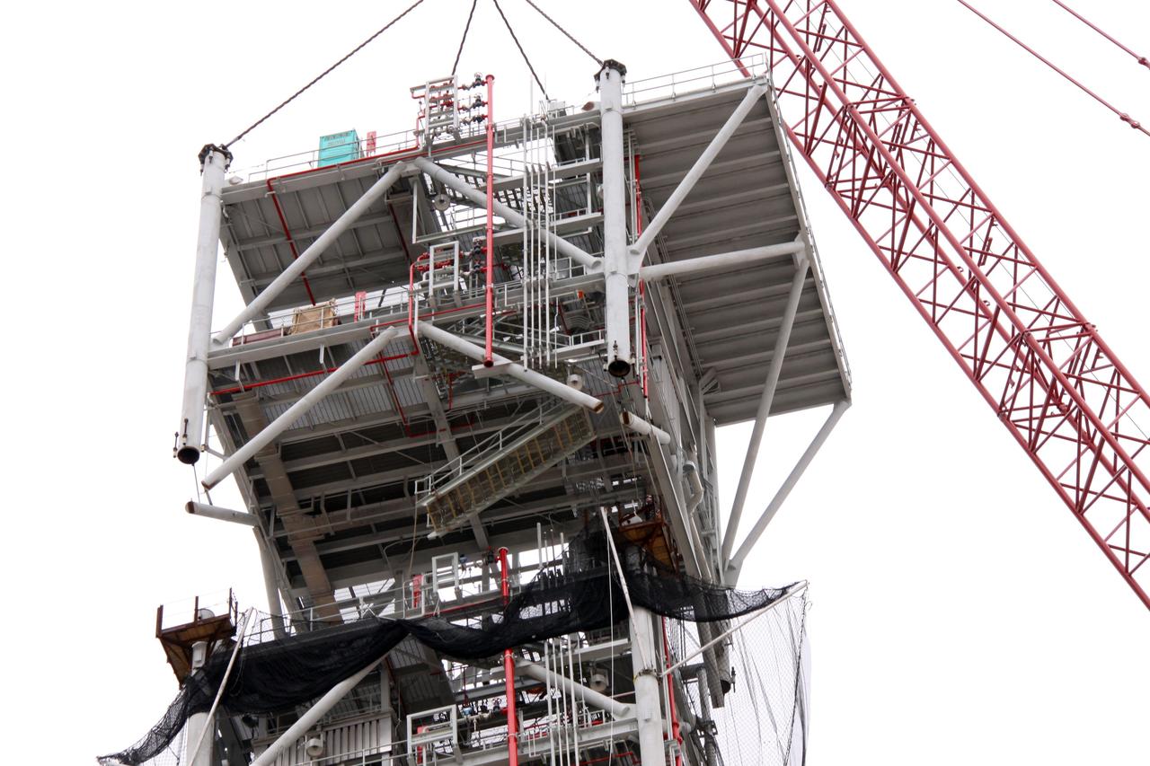
CAPE CANAVERAL, Fla. – At NASA's Kennedy Space Center in Florida, a crane slowly eases the eighth tower segment of a new mobile launcher, or ML, being constructed to support the Constellation Program, into position over the seven segments already secured to the launcher's surface. When completed, the tower will be approximately 345 feet tall and have multiple platforms for personnel access. The construction is under way at the mobile launcher park site area north of Kennedy's Vehicle Assembly Building. The launcher will provide a base to launch the Ares I rocket, designed to transport the Orion crew exploration vehicle, its crew and cargo to low Earth orbit. Its base is being made lighter than space shuttle mobile launcher platforms so the crawler-transporter can pick up the heavier load of the tower and taller rocket. For information on the Ares I, visit http://www.nasa.gov/ares. Photo credit: NASA/Jack Pfaller
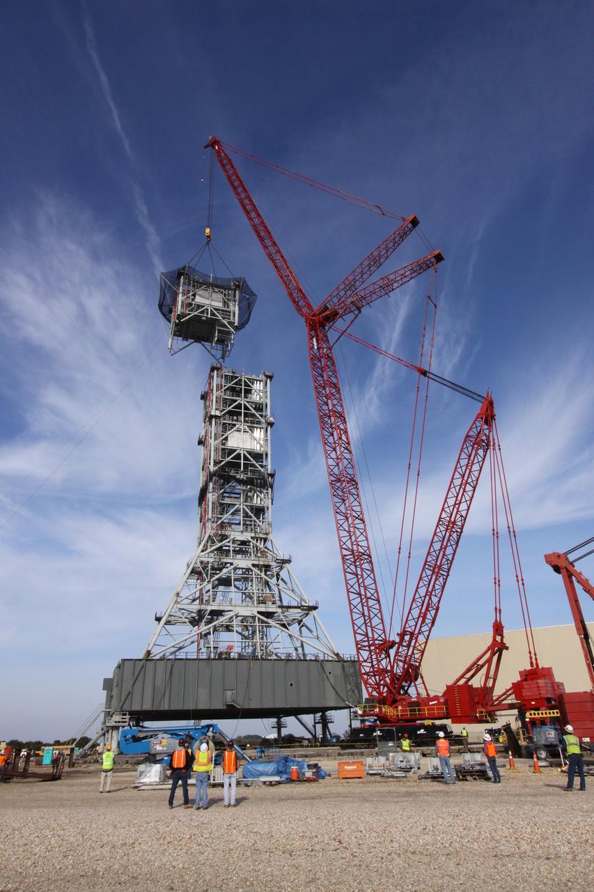
CAPE CANAVERAL, Fla. – At NASA's Kennedy Space Center in Florida, a crane slowly eases the seventh tower segment of a new mobile launcher, or ML, being constructed to support the Constellation Program, into position over the six segments already secured to the launcher's surface. When completed, the tower will be approximately 345 feet tall and have multiple platforms for personnel access. The construction is under way at the mobile launcher park site area north of Kennedy's Vehicle Assembly Building. The launcher will provide a base to launch the Ares I rocket, designed to transport the Orion crew exploration vehicle, its crew and cargo to low Earth orbit. Its base is being made lighter than space shuttle mobile launcher platforms so the crawler-transporter can pick up the heavier load of the tower and taller rocket. For information on the Ares I, visit http://www.nasa.gov/ares. Photo credit: NASA/Jack Pfaller
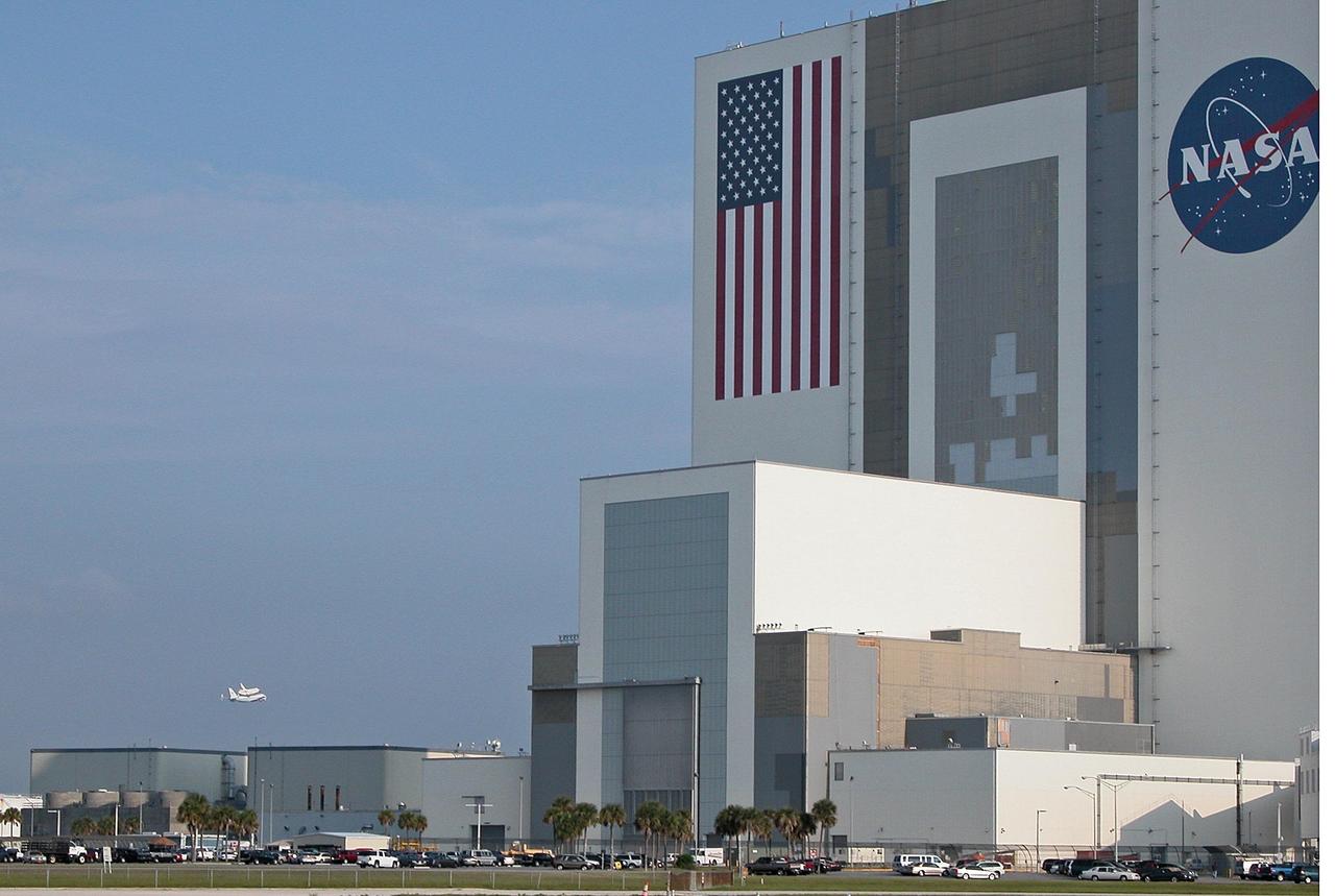
KENNEDY SPACE CENTER, FLA. -- Through broken clouds, the shuttle carrier aircraft, or SCA, and its passenger Atlantis ease their way past the Vehicle Assembly Building, at right, for a landing at the KSC Shuttle Landing Facility, known as the SLF. The aircraft is a modified Boeing 747 jetliner. Atlantis landed at Edwards Air Force Base in California to end mission STS-117. The return to KSC began July 1 and took three days after stops across the country for fuel. The last stop was at Ft. Campbell in Kentucky. Weather conditions over the last leg postponed the return trip until July 3. Touchdown was at 8:27 a.m. EDT. Atlantis will be removed from the back of the SCA via the mate/demate device at the SLF. It will then be towed to the Orbiter Processing Facility to begin processing for its next launch, mission STS-122 in December. Photo credit: NASA/Debbie Odom
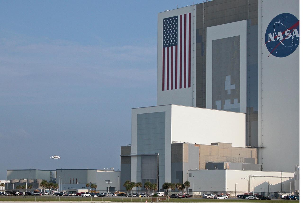
Through broken clouds, the shuttle carrier aircraft, or SCA, and its passenger Atlantis ease their way past the Vehicle Assembly Building, at right, for a landing at the KSC Shuttle Landing Facility, known as the SLF. The aircraft is a modified Boeing 747 jetliner. Atlantis landed at Edwards Air Force Base in California to end mission STS-117. The return to KSC began July 1 and took three days after stops across the country for fuel. The last stop was at Ft. Campbell in Kentucky. Weather conditions over the last leg postponed the return trip until July 3. Touchdown was at 8:27 a.m. EDT. Atlantis will be removed from the back of the SCA via the mate/demate device at the SLF. It will then be towed to the Orbiter Processing Facility to begin processing for its next launch, mission STS-122 in December.
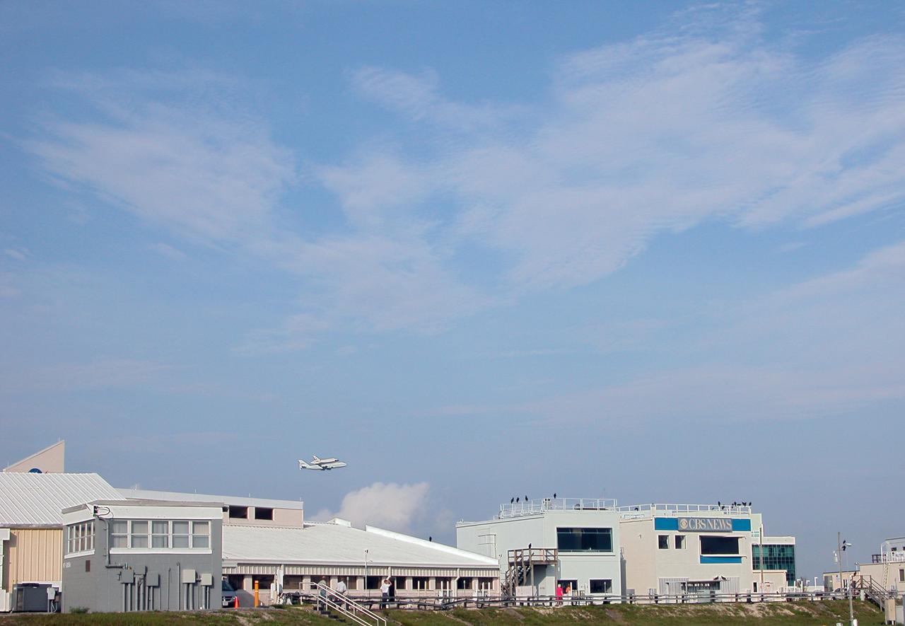
On a morning where broken clouds filled the sky of Central Florida, the shuttle carrier aircraft, or SCA, and its passenger Atlantis ease their way past the NASA News Center for a landing at the KSC Shuttle Landing Facility, known as the SLF. The aircraft is a modified Boeing 747 jetliner Atlantis landed at Edwards Air Force Base in California to end mission STS-117. The return to KSC began July 1 and took three days after stops across the country for fuel. The last stop was at Ft. Campbell in Kentucky. Weather conditions over the last leg postponed the return trip until July 3. Touchdown was at 8:27 a.m. EDT. Atlantis will be removed from the back of the SCA via the mate/demate device at the SLF. It will then be towed to the Orbiter Processing Facility to begin processing for its next launch, mission STS-122 in December.
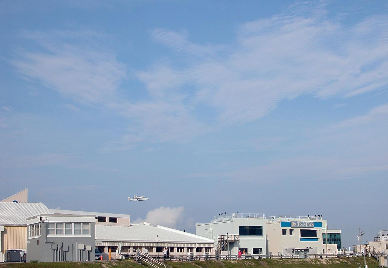
KENNEDY SPACE CENTER, FLA. -- On a morning where broken clouds filled the sky of Central Florida, the shuttle carrier aircraft, or SCA, and its passenger Atlantis ease their way past the NASA News Center for a landing at the KSC Shuttle Landing Facility, known as the SLF. The aircraft is a modified Boeing 747 jetliner Atlantis landed at Edwards Air Force Base in California to end mission STS-117. The return to KSC began July 1 and took three days after stops across the country for fuel. The last stop was at Ft. Campbell in Kentucky. Weather conditions over the last leg postponed the return trip until July 3. Touchdown was at 8:27 a.m. EDT. Atlantis will be removed from the back of the SCA via the mate/demate device at the SLF. It will then be towed to the Orbiter Processing Facility to begin processing for its next launch, mission STS-122 in December. Photo credit: NASA/Debbie Odom
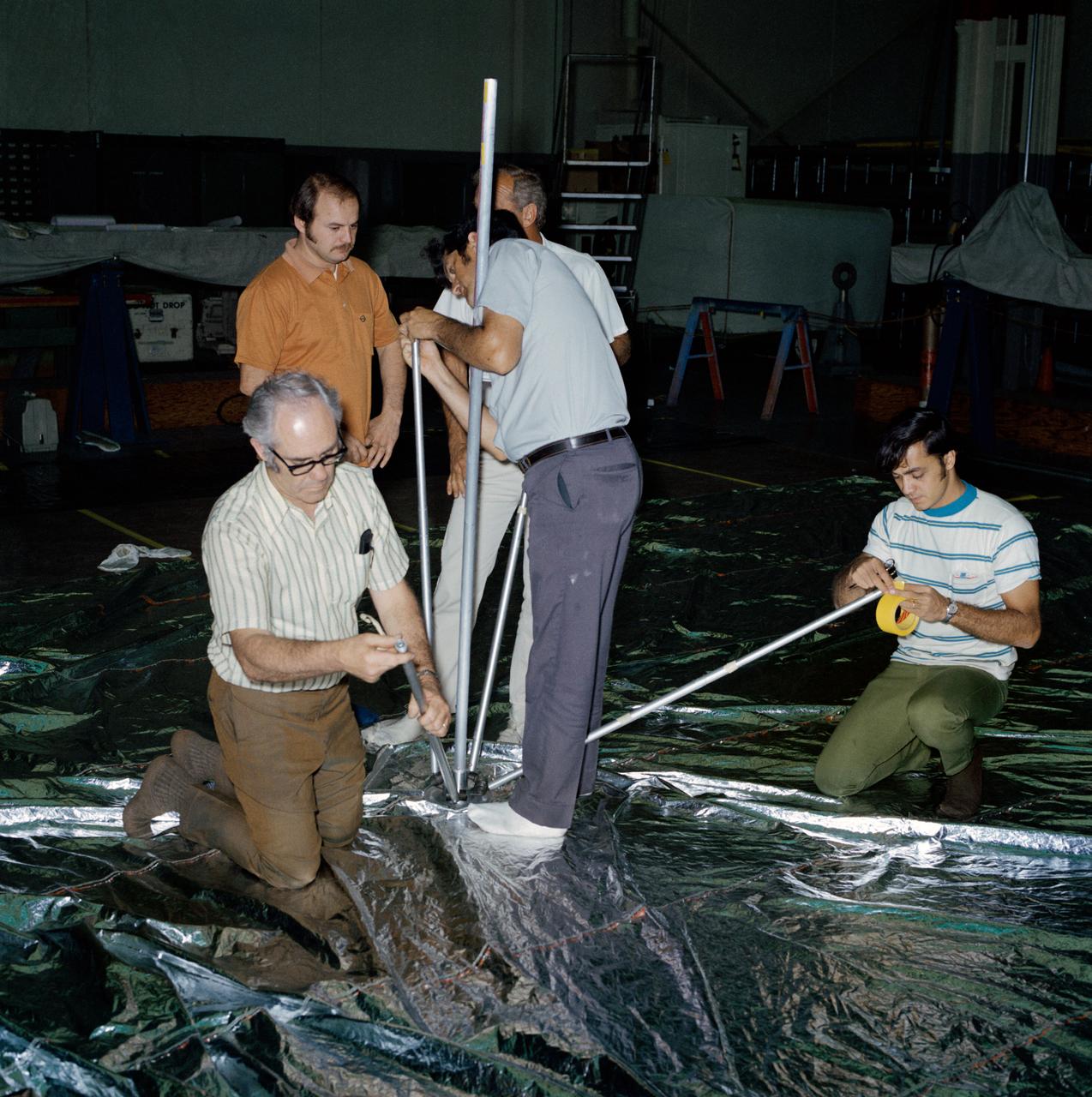
S73-26380 (23 May 1973) --- Technicians in the Technical Services shop in Building 10 work on the fabrication of the umbrella-like mechanical device called the “parasol” during Skylab 2 preflight preparations at NASA's Johnson Space Center. Here, they are attaching the telescoping extension rods to the canopy. The “parasol” is designed to fit into the TO27 experiment photometer canister. The canopy is 24 feet by 22 feet. The sunshade device will be deployed through the solar scientific airlock in the side of the OWS. The “parasol” solar shield is considered the prime possibility for use as the OWS sunshade because it will not require EVA by the Skylab 2 crewmen, because of the operational ease of using it, and because of the simplicity of the device which minimizes crew training. Photo credit: NASA
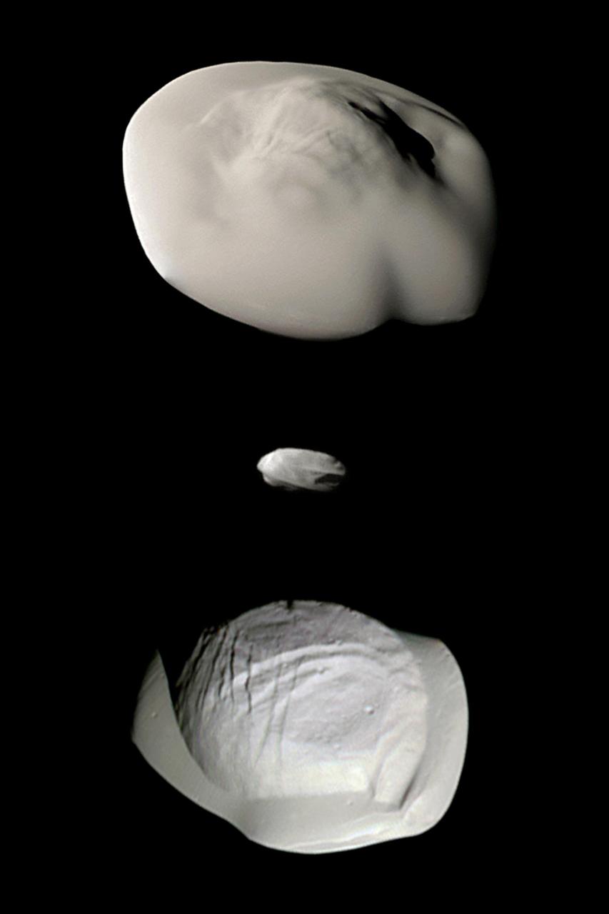
This montage of views from NASA's Cassini spacecraft shows three of Saturn's small ring moons: Atlas, Daphnis and Pan at the same scale for ease of comparison. Two differences between Atlas and Pan are obvious in this montage. Pan's equatorial band is much thinner and more sharply defined, and the central mass of Atlas (the part underneath the smooth equatorial band) appears to be smaller than that of Pan. Images of Atlas and Pan taken using infrared, green and ultraviolet spectral filters were combined to create enhanced-color views, which highlight subtle color differences across the moons' surfaces at wavelengths not visible to human eyes. (The Daphnis image was colored using the same green filter image for all three color channels, adjusted to have a realistic appearance next to the other two moons.) All of these images were taken using the Cassini spacecraft narrow-angle camera. The images of Atlas were acquired on April 12, 2017, at a distance of 10,000 miles (16,000 kilometers) and at a sun-moon-spacecraft angle (or phase angle) of 37 degrees. The images of Pan were taken on March 7, 2017, at a distance of 16,000 miles (26,000 kilometers) and a phase angle of 21 degrees. The Daphnis image was obtained on Jan. 16, 2017, at a distance of 17,000 miles (28,000 kilometers) and at a phase angle of 71 degrees. All images are oriented so that north is up. A monochrome version is available at https://photojournal.jpl.nasa.gov/catalog/PIA21449
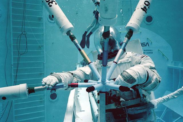
Once the United States' space program had progressed from Earth's orbit into outerspace, the prospect of building and maintaining a permanent presence in space was realized. To accomplish this feat, NASA launched a temporary workstation, Skylab, to discover the effects of low gravity and weightlessness on the human body, and also to develop tools and equipment that would be needed in the future to build and maintain a more permanent space station. The structures, techniques, and work schedules had to be carefully designed to fit this unique construction site. The components had to be lightweight for transport into orbit, yet durable. The station also had to be made with removable parts for easy servicing and repairs by astronauts. All of the tools necessary for service and repairs had to be designed for easy manipulation by a suited astronaut. And construction methods had to be efficient due to limited time the astronauts could remain outside their controlled environment. In lieu of all the specific needs for this project, an environment on Earth had to be developed that could simulate a low gravity atmosphere. A Neutral Buoyancy Simulator (NBS) was constructed by NASA Marshall Space Flight Center (MSFC) in 1968. Since then, NASA scientists have used this facility to understand how humans work best in low gravity and also provide information about the different kinds of structures that can be built. Pictured is a Massachusetts Institute of Technology (MIT) student working in a spacesuit on the Experimental Assembly of Structures in Extravehicular Activity (EASE) project which was developed as a joint effort between MFSC and MIT. The EASE experiment required that crew members assemble small components to form larger components, working from the payload bay of the space shuttle.

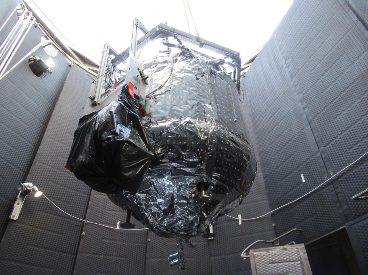
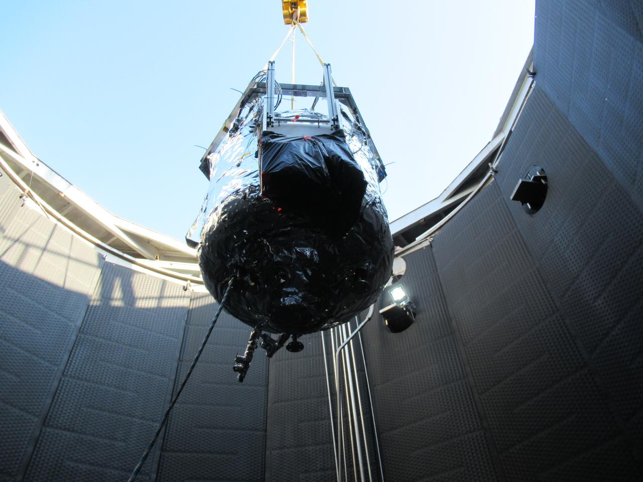
These photos show how teams at NASA’s Marshall Space Flight Center in Huntsville, Alabama, are testing an innovative approach to achieve zero boiloff storage of liquid hydrogen using two stages of active cooling, which could prevent the loss of valuable propellant during future long-duration spaceflight missions. Test teams installed the propellant tank in Test Stand 300 at NASA Marshall in early June, and the 90-day test campaign is scheduled to conclude in September. The tank is wrapped in a multi-layer insulation blanket that includes a thin aluminum heat shield fitted between layers. A second set of tubes, carrying helium at about minus 298 Fahrenheit, is integrated into the shield. This intermediate cooling layer intercepts and rejects incoming heat before it reaching the tank, easing the heat load on the tube-on-tank system. The Cryogenic Fluid Management Portfolio Project is a cross-agency team based at NASA Marshall and the agency’s Glenn Research Center in Cleveland. The cryogenic portfolio’s work is under NASA’s Technology Demonstration Missions Program, part of NASA’s Space Technology Mission Directorate, and is comprised of more than 20 individual technology development activities. For more information, contact NASA Marshall’s Office of Communications at 256-544-0034.
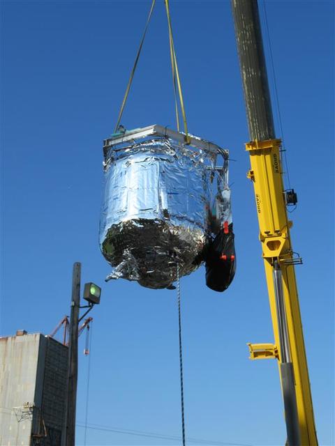
These photos show how teams at NASA’s Marshall Space Flight Center in Huntsville, Alabama, are testing an innovative approach to achieve zero boiloff storage of liquid hydrogen using two stages of active cooling, which could prevent the loss of valuable propellant during future long-duration spaceflight missions. Test teams installed the propellant tank in Test Stand 300 at NASA Marshall in early June, and the 90-day test campaign is scheduled to conclude in September. The tank is wrapped in a multi-layer insulation blanket that includes a thin aluminum heat shield fitted between layers. A second set of tubes, carrying helium at about minus 298 Fahrenheit, is integrated into the shield. This intermediate cooling layer intercepts and rejects incoming heat before it reaching the tank, easing the heat load on the tube-on-tank system. The Cryogenic Fluid Management Portfolio Project is a cross-agency team based at NASA Marshall and the agency’s Glenn Research Center in Cleveland. The cryogenic portfolio’s work is under NASA’s Technology Demonstration Missions Program, part of NASA’s Space Technology Mission Directorate, and is comprised of more than 20 individual technology development activities. For more information, contact NASA Marshall’s Office of Communications at 256-544-0034.
These photos show how teams at NASA’s Marshall Space Flight Center in Huntsville, Alabama, are testing an innovative approach to achieve zero boiloff storage of liquid hydrogen using two stages of active cooling, which could prevent the loss of valuable propellant during future long-duration spaceflight missions. Test teams installed the propellant tank in Test Stand 300 at NASA Marshall in early June, and the 90-day test campaign is scheduled to conclude in September. The tank is wrapped in a multi-layer insulation blanket that includes a thin aluminum heat shield fitted between layers. A second set of tubes, carrying helium at about minus 298 Fahrenheit, is integrated into the shield. This intermediate cooling layer intercepts and rejects incoming heat before it reaching the tank, easing the heat load on the tube-on-tank system. The Cryogenic Fluid Management Portfolio Project is a cross-agency team based at NASA Marshall and the agency’s Glenn Research Center in Cleveland. The cryogenic portfolio’s work is under NASA’s Technology Demonstration Missions Program, part of NASA’s Space Technology Mission Directorate, and is comprised of more than 20 individual technology development activities. For more information, contact NASA Marshall’s Office of Communications at 256-544-0034.
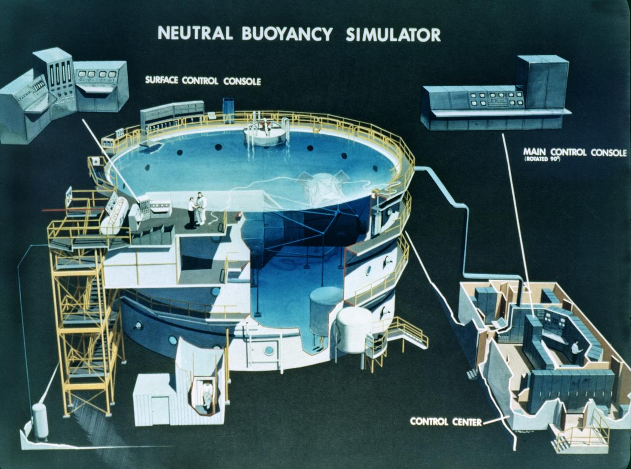
This is a cutaway illustration of the Neutral Buoyancy Simulator (NBS) at the Marshall Space Flight Center (MSFC ). The MSFC NBS provided an excellent environment for testing hardware to examine how it would operate in space and for evaluating techniques for space construction and spacecraft servicing. Here, engineers, designers, and astronauts performed various tests to develop basic concepts, preliminary designs, final designs, and crew procedures. The NBS was constructed of welded steel with polyester-resin coating. The water tank was 75-feet (22.9- meters) in diameter, 40-feet (12.2-meters) deep, and held 1.32 million gallons of water. Since it opened for operation in 1968, the NBS had supported a number of successful space missions, such as the Skylab, Solar Maximum Mission Satellite, Marned Maneuvering Unit, Experimental Assembly of Structures in Extravehicular Activity/Assembly Concept for Construction of Erectable Space Structures (EASE/ACCESS), the Hubble Space Telescope, and the Space Station. The function of the MSFC NBS was moved to the larger simulator at the Johnson Space Center and is no longer operational.
![This white, purple, and pink surface is located on the floor of an impact crater on the southeast rim of the larger Vinogradov Crater in southern Margaritifer Terra. The surface consists of what is left of a series of thin layers that subsequently eroded to create a "bullseye" pattern. The rough, etched appearance of the surface is similar-looking to deposits in other craters in the region and that are often associated with alluvial fans. The apparent ease and manner in which the materials are eroded relative to nearby fans and crater materials suggests they are fine-grained and the dominant agent of erosion is the wind. Although the origin of the deposits remains speculative, their physical character and common association with alluvial fans suggests they may be the result of deposition into a shallow lake or playa enabled by water flowing off the adjacent fan surfaces. The map is projected here at a scale of 25 centimeters (9.8 inches) per pixel. [The original image scale is 26 centimeters (10.2 inches) per pixel (with 1 x 1 binning); objects on the order of 78 centimeters (30.7 inches) across are resolved.] North is up. http://photojournal.jpl.nasa.gov/catalog/PIA21560](https://images-assets.nasa.gov/image/PIA21560/PIA21560~medium.jpg)
This white, purple, and pink surface is located on the floor of an impact crater on the southeast rim of the larger Vinogradov Crater in southern Margaritifer Terra. The surface consists of what is left of a series of thin layers that subsequently eroded to create a "bullseye" pattern. The rough, etched appearance of the surface is similar-looking to deposits in other craters in the region and that are often associated with alluvial fans. The apparent ease and manner in which the materials are eroded relative to nearby fans and crater materials suggests they are fine-grained and the dominant agent of erosion is the wind. Although the origin of the deposits remains speculative, their physical character and common association with alluvial fans suggests they may be the result of deposition into a shallow lake or playa enabled by water flowing off the adjacent fan surfaces. The map is projected here at a scale of 25 centimeters (9.8 inches) per pixel. [The original image scale is 26 centimeters (10.2 inches) per pixel (with 1 x 1 binning); objects on the order of 78 centimeters (30.7 inches) across are resolved.] North is up. http://photojournal.jpl.nasa.gov/catalog/PIA21560
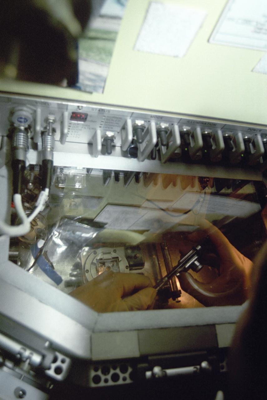
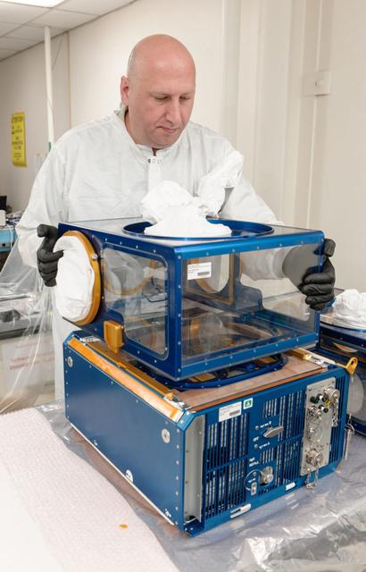
The first United States Microgravity Laboratory (USML-1) provided scientific research in materials science, fluid dynamics, biotechnology, and combustion science in a weightless environment inside the Spacelab module. This photograph is a close-up view of the Glovebox in operation during the mission. The Spacelab Glovebox, provided by the European Space Agency, offers experimenters new capabilities to test and develop science procedures and technologies in microgravity. It enables crewmembers to handle, transfer, and otherwise manipulate materials in ways that are impractical in the open Spacelab. The facility is equipped with three doors: a central port through which experiments are placed in the Glovebox and two glovedoors on both sides with an attachment for gloves or adjustable cuffs and adapters for cameras. The Glovebox has an enclosed compartment that offers a clean working space and minimizes the contamination risks to both Spacelab and experiment samples. Although fluid containment and ease of cleanup are major benefits provided by the facility, it can also contain powders and bioparticles; toxic, irritating, or potentially infectious materials; and other debris produced during experiment operations. The facility is equipped with photographic/video capabilities and permits mounting a microscope. For the USML-1 mission, the Glovebox experiments fell into four basic categories: fluid dynamics, combustion science, crystal growth, and technology demonstration. The USML-1 flew aboard the STS-50 mission in June 1992.
These photos show how teams at NASA’s Marshall Space Flight Center in Huntsville, Alabama, are testing an innovative approach to achieve zero boiloff storage of liquid hydrogen using two stages of active cooling, which could prevent the loss of valuable propellant during future long-duration spaceflight missions. Test teams installed the propellant tank in Test Stand 300 at NASA Marshall in early June, and the 90-day test campaign is scheduled to conclude in September. The tank is wrapped in a multi-layer insulation blanket that includes a thin aluminum heat shield fitted between layers. A second set of tubes, carrying helium at about minus 298 Fahrenheit, is integrated into the shield. This intermediate cooling layer intercepts and rejects incoming heat before it reaching the tank, easing the heat load on the tube-on-tank system. The Cryogenic Fluid Management Portfolio Project is a cross-agency team based at NASA Marshall and the agency’s Glenn Research Center in Cleveland. The cryogenic portfolio’s work is under NASA’s Technology Demonstration Missions Program, part of NASA’s Space Technology Mission Directorate, and is comprised of more than 20 individual technology development activities. For more information, contact NASA Marshall’s Office of Communications at 256-544-0034.
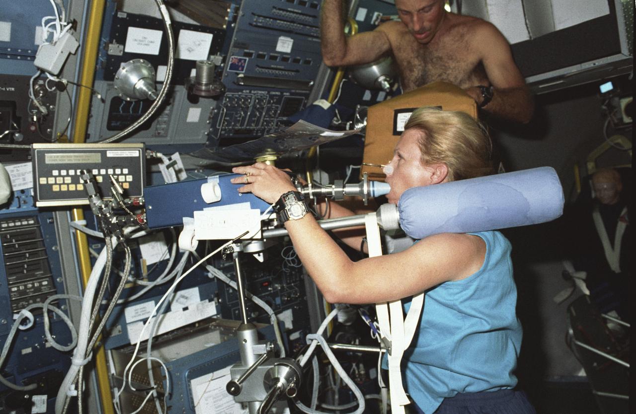
Spacelab Life Science -1 (SLS-1) was the first Spacelab mission dedicated solely to life sciences. The main purpose of the SLS-1 mission was to study the mechanisms, magnitudes, and time courses of certain physiological changes that occur during space flight, to investigate the consequences of the body's adaptation to microgravity and readjustment to Earth's gravity, and bring the benefits back home to Earth. The mission was designed to explore the responses of the heart, lungs, blood vessels, kidneys, and hormone-secreting glands to microgravity and related body fluid shifts; examine the causes of space motion sickness; and study changes in the muscles, bones, and cells. This photograph shows astronaut Rhea Seddon conducting an inflight study of the Cardiovascular Deconditioning experiment by breathing into the cardiovascular rebreathing unit. This experiment focused on the deconditioning of the heart and lungs and changes in cardiopulmonary function that occur upon return to Earth. By using noninvasive techniques of prolonged expiration and rebreathing, investigators can determine the amount of blood pumped out of the heart (cardiac output), the ease with which blood flows through all the vessels (total peripheral resistance), oxygen used and carbon dioxide released by the body, and lung function and volume changes. SLS-1 was launched aboard the Space Shuttle Orbiter Columbia (STS-40) on June 5, 1995.
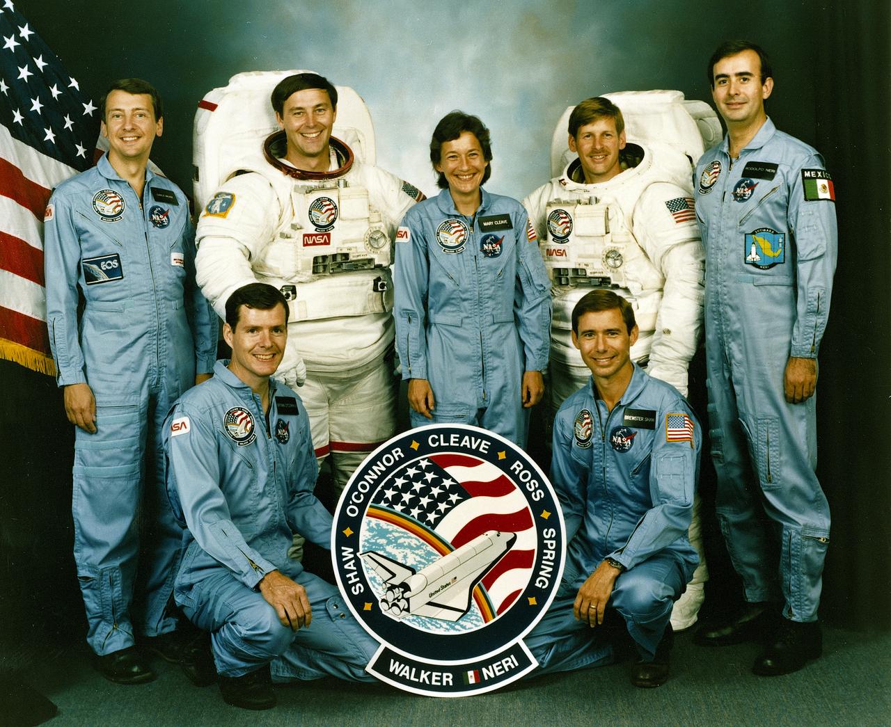
The crew assigned to the STS-61B mission included (kneeling left to right) Bryan D. O’conner, pilot; and Brewster H. Shaw, commander. On the back row, left to right, are Charles D. Walker, payload specialist; mission specialists Jerry L. Ross, Mary L. Cleave, and Sherwood C. Spring; and Rodolpho Neri Vela, payload specialist. Launched aboard the Space Shuttle Atlantis November 28, 1985 at 7:29:00 pm (EST), the STS-61B mission’s primary payload included three communications satellites: MORELOS-B (Mexico); AUSSAT-2 (Autralia); and SATCOM KU-2 (RCA Americom. Two experiments were conducted to test assembling erectable structures in space: EASE (Experimental Assembly of Structures in Extravehicular Activity), and ACCESS (Assembly Concept for Construction of Erectable Space Structure). In a joint venture between NASA/Langley Research Center in Hampton, VA and Marshall Space Flight Center (MSFC), the Assembly Concept for Construction of Erectable Space Structures (ACCESS) was developed and demonstrated at MSFC's Neutral Buoyancy Simulator (NBS). The primary objective of this experiment was to test the ACCESS structural assembly concept for suitability as the framework for larger space structures and to identify ways to improve the productivity of space construction.
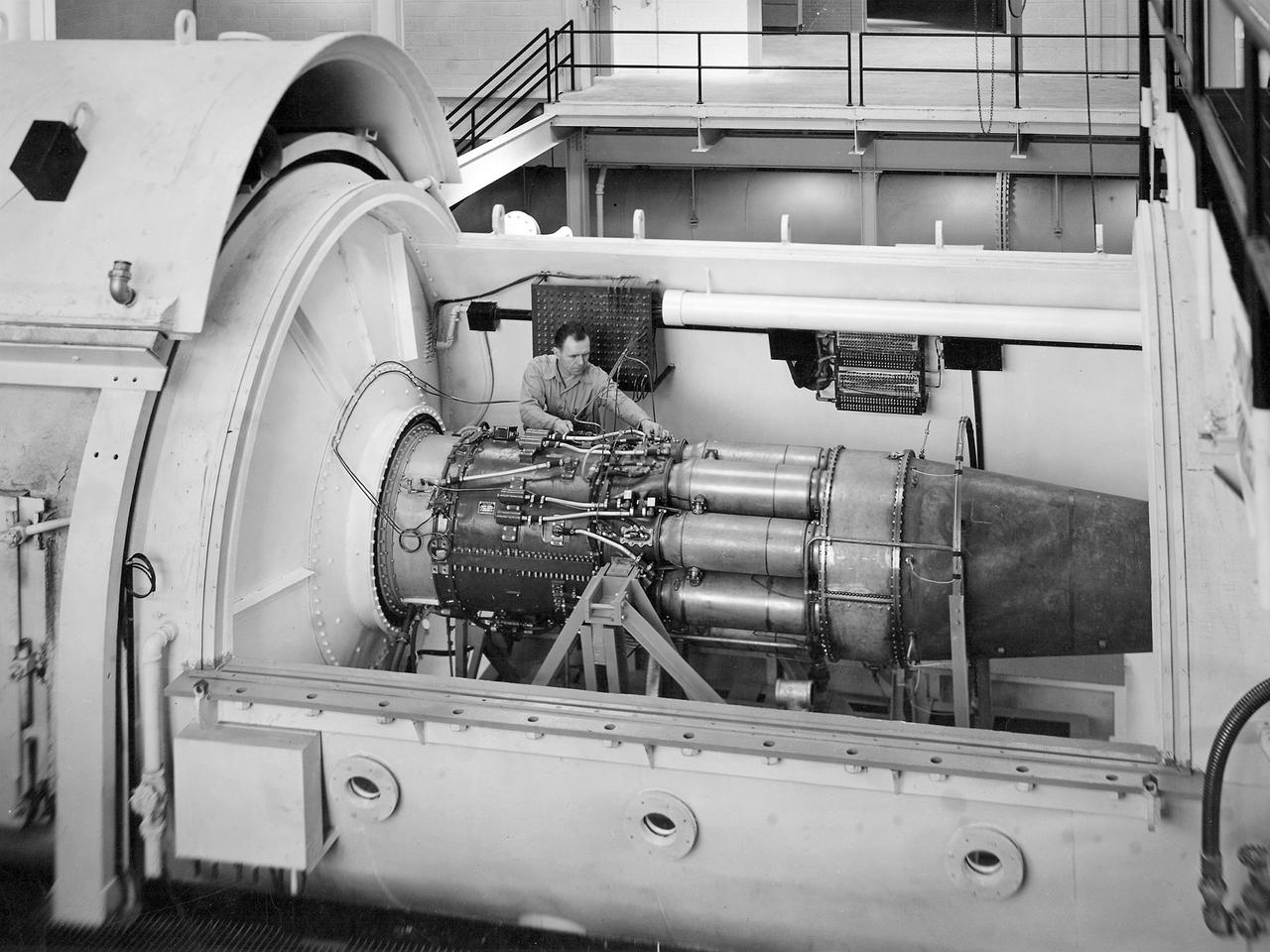
One of the two altitude simulating-test chambers in Engine Research Building at the National Advisory Committee for Aeronautics (NACA) Lewis Flight Propulsion Laboratory. The two chambers were collectively referred to as the Four Burner Area. NACA Lewis’ Altitude Wind Tunnel was the nation’s first major facility used for testing full-scale engines in conditions that realistically simulated actual flight. The wind tunnel was such a success in the mid-1940s that there was a backlog of engines waiting to be tested. The Four Burner chambers were quickly built in 1946 and 1947 to ease the Altitude Wind Tunnel’s congested schedule. The Four Burner Area was located in the southwest wing of the massive Engine Research Building, across the road from the Altitude Wind Tunnel. The two chambers were 10 feet in diameter and 60 feet long. The refrigeration equipment produced the temperatures and the exhauster equipment created the low pressures present at altitudes up to 60,000 feet. In 1947 the Rolls Royce Nene was the first engine tested in the new facility. The mechanic in this photograph is installing a General Electric J-35 engine. Over the next ten years, a variety of studies were conducted using the General Electric J-47 and Wright Aeronautical J-65 turbojets. The two test cells were occasionally used for rocket engines between 1957 and 1959, but other facilities were better suited to the rocket engine testing. The Four Burner Area was shutdown in 1959. After years of inactivity, the facility was removed from the Engine Research Building in late 1973 in order to create the High Temperature and Pressure Combustor Test Facility.
Once the United States' space program had progressed from Earth's orbit into outerspace, the prospect of building and maintaining a permanent presence in space was realized. To accomplish this feat, NASA launched a temporary workstation, Skylab, to discover the effects of low gravity and weightlessness on the human body, and also to develop tools and equipment that would be needed in the future to build and maintain a more permanent space station. The structures, techniques, and work schedules had to be carefully designed to fit this unique construction site. The components had to be lightweight for transport into orbit, yet durable. The station also had to be made with removable parts for easy servicing and repairs by astronauts. All of the tools necessary for service and repairs had to be designed for easy manipulation by a suited astronaut. And construction methods had to be efficient due to limited time the astronauts could remain outside their controlled environment. In lieu of all the specific needs for this project, an environment on Earth had to be developed that could simulate a low gravity atmosphere. A Neutral Buoyancy Simulator (NBS) was constructed by NASA Marshall Space Flight Center (MSFC) in 1968. Since then, NASA scientists have used this facility to understand how humans work best in low gravity and also provide information about the different kinds of structures that can be built.Pictured is an experiment where the astronaut is required to move a large object which weighed 19,000 pounds. It was moved with realitive ease once the astronaut became familiar with his environment and his near weightless condition. Experiments of this nature provided scientists with the information needed regarding weight and mass allowances astronauts could manage in preparation for building a permanent space station in the future.
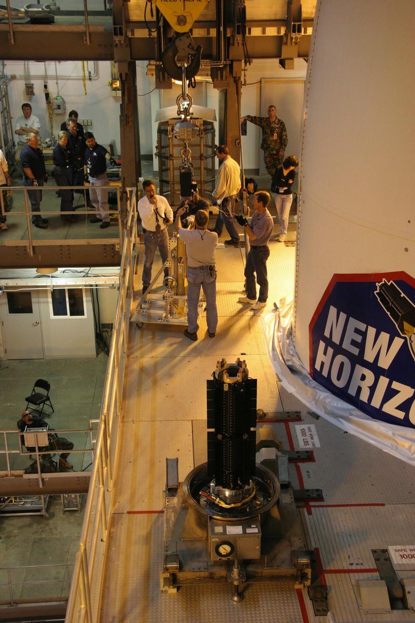
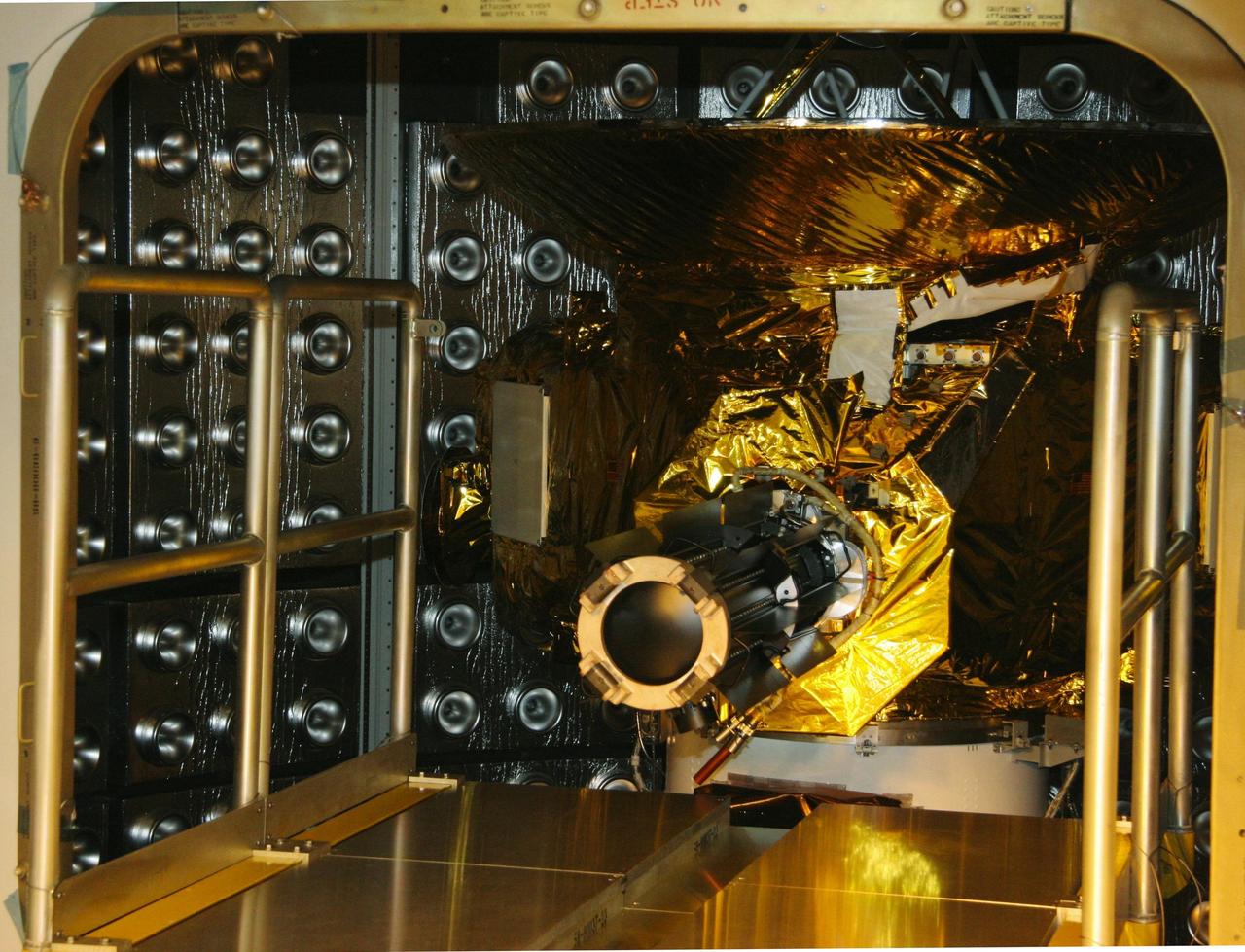
KENNEDY SPACE CENTER, FLA. — On Complex 41 at Cape Canaveral Air Force Station in Florida, the radioisotope thermoelectric generator (RTG) in the foreground has been removed from its caged enclosure. The RTG will be installed on the New Horizons spacecraft encapsulated inside the fairing, at right. Designed and integrated at the Johns Hopkins University Applied Physics Laboratory (APL) in Laurel, Md., New Horizons will launch on a nine-and-a-half-year voyage to Pluto. Typical of RTG-based systems, as on past outer-planet missions, New Horizons does not have a battery for storing power. At the start of the mission, the RTG, which provides power through the natural radioactive decay of plutonium dioxide fuel, will supply approximately 240 watts (at 30 volts of direct current) - the spacecraft’s shunt regulator unit maintains a steady input from the RTG and dissipates power the spacecraft cannot use at a given time. By July 2015 (the earliest Pluto encounter date) that supply decreases to 200 watts at the same voltage, so New Horizons will ease the strain on its limited power source by cycling science instruments during planetary encounters. On Complex 41 at Cape Canaveral Air Force Station in Florida, workers on the ground oversee the radioisotope thermoelectric generator (RTG) being lifted into the Vertical Integration Facility. The RTG will be installed on the New Horizons spacecraft within the fairing at the top of the Atlas V launch vehicle. Designed and integrated at the Johns Hopkins University Applied Physics Laboratory (APL) in Laurel, Md., New Horizons will launch on a nine-and-a-half-year voyage to Pluto. Typical of RTG-based systems, as on past outer-planet missions, New Horizons does not have a battery for storing power. At the start of the mission, the RTG, which provides power through the natural radioactive decay of plutonium dioxide fuel, will supply approximately 240 watts (at 30 volts of direct current) - the spacecraft’s shunt regulato
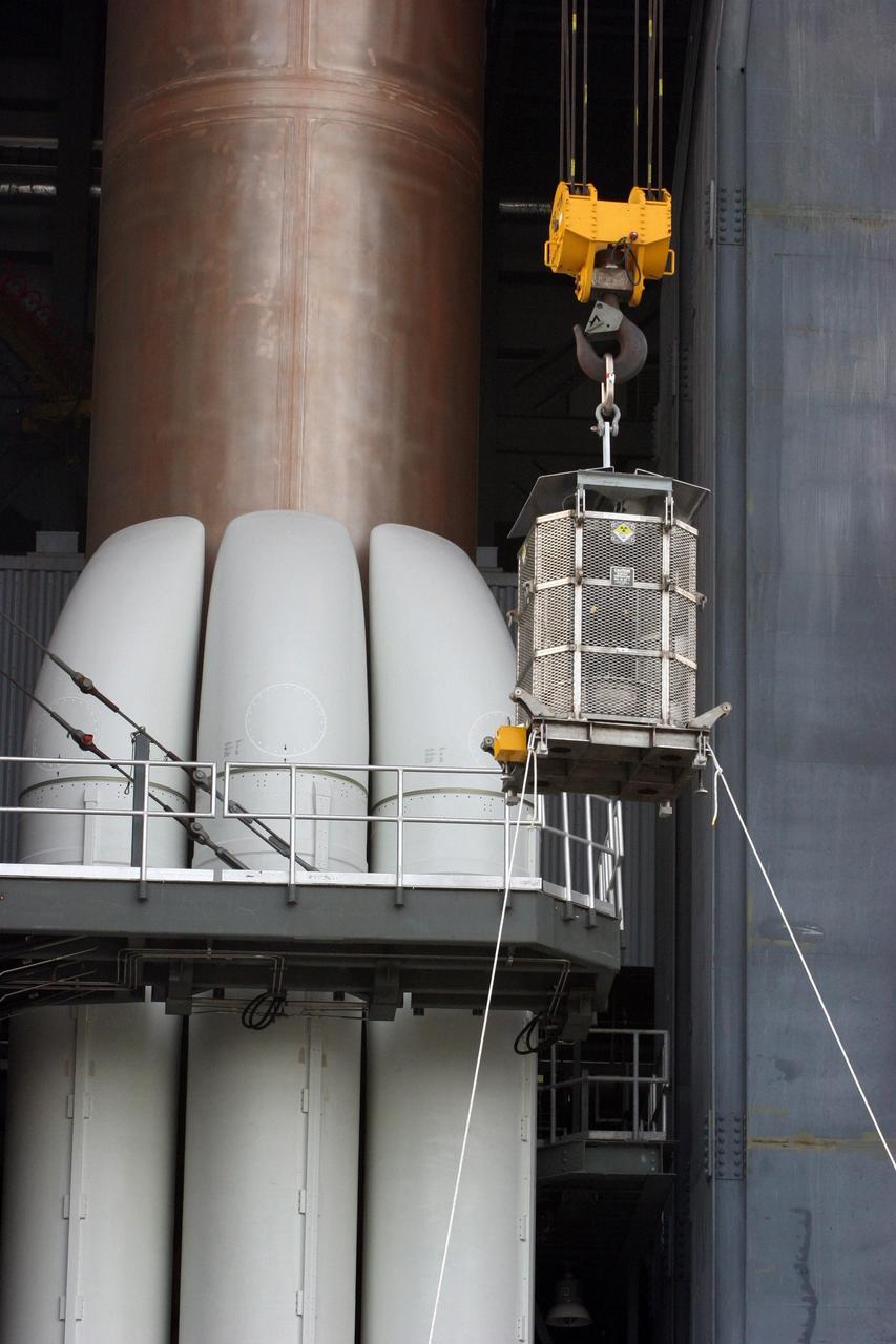
KENNEDY SPACE CENTER, FLA. — On Complex 41 at Cape Canaveral Air Force Station in Florida, the radioisotope thermoelectric generator (RTG) is being lifted into the Vertical Integration Facility. The RTG will be installed on the New Horizons spacecraft within the fairing at the top of the Atlas V launch vehicle. Designed and integrated at the Johns Hopkins University Applied Physics Laboratory (APL) in Laurel, Md., New Horizons will launch on a nine-and-a-half-year voyage to Pluto. Typical of RTG-based systems, as on past outer-planet missions, New Horizons does not have a battery for storing power. At the start of the mission, the RTG, which provides power through the natural radioactive decay of plutonium dioxide fuel, will supply approximately 240 watts (at 30 volts of direct current) - the spacecraft’s shunt regulator unit maintains a steady input from the RTG and dissipates power the spacecraft cannot use at a given time. By July 2015 (the earliest Pluto encounter date) that supply decreases to 200 watts at the same voltage, so New Horizons will ease the strain on its limited power source by cycling science instruments during planetary encounters. On Complex 41 at Cape Canaveral Air Force Station in Florida, workers on the ground oversee the radioisotope thermoelectric generator (RTG) being lifted into the Vertical Integration Facility. The RTG will be installed on the New Horizons spacecraft within the fairing at the top of the Atlas V launch vehicle. Designed and integrated at the Johns Hopkins University Applied Physics Laboratory (APL) in Laurel, Md., New Horizons will launch on a nine-and-a-half-year voyage to Pluto. Typical of RTG-based systems, as on past outer-planet missions, New Horizons does not have a battery for storing power. At the start of the mission, the RTG, which provides power through the natural radioactive decay of plutonium dioxide fuel, will supply approximately 240 watts (at 30 volts of direct current) - the spacecraft’s shu
KENNEDY SPACE CENTER, FLA. — On Complex 41 at Cape Canaveral Air Force Station in Florida, the radioisotope thermoelectric generator (RTG) is attached to the New Horizons spacecraft inside the fairing. Designed and integrated at the Johns Hopkins University Applied Physics Laboratory (APL) in Laurel, Md., New Horizons will launch on a nine-and-a-half-year voyage to Pluto. Typical of RTG-based systems, as on past outer-planet missions, New Horizons does not have a battery for storing power. At the start of the mission, the RTG, which provides power through the natural radioactive decay of plutonium dioxide fuel, will supply approximately 240 watts (at 30 volts of direct current) - the spacecraft’s shunt regulator unit maintains a steady input from the RTG and dissipates power the spacecraft cannot use at a given time. By July 2015 (the earliest Pluto encounter date) that supply decreases to 200 watts at the same voltage, so New Horizons will ease the strain on its limited power source by cycling science instruments during planetary encounters. On Complex 41 at Cape Canaveral Air Force Station in Florida, workers on the ground oversee the radioisotope thermoelectric generator (RTG) being lifted into the Vertical Integration Facility. The RTG will be installed on the New Horizons spacecraft within the fairing at the top of the Atlas V launch vehicle. Designed and integrated at the Johns Hopkins University Applied Physics Laboratory (APL) in Laurel, Md., New Horizons will launch on a nine-and-a-half-year voyage to Pluto. Typical of RTG-based systems, as on past outer-planet missions, New Horizons does not have a battery for storing power. At the start of the mission, the RTG, which provides power through the natural radioactive decay of plutonium dioxide fuel, will supply approximately 240 watts (at 30 volts of direct current) - the spacecraft’s shunt regulator unit maintains a steady input from the RTG and dissipates power the spacecraft cannot use at a give

For almost 2,000 years, the River Thames has served as the life force of London, capital of the United Kingdom and one of the world's most famous cities. In AD 43 the Romans established the trading settlement of Londinium at a favorable crossing point on the river. The Romans remained until the 5th century, when the city came under Saxon control. The early 17th century saw enormous growth, but the deadly plague of 1664 and 1665 ravaged the population, and in the following year the Great Fire, which burned for four days, destroyed most of the city. A public transportation system and other city services in the early 19th century eased many of the increasing urban problems of the burgeoning capital of the wealthy British Empire. After coping with the devastating effects of bombing during World War II and the gradual dismantling of the empire, London today thrives as a vital modern metropolis. London is one of 100 cities being studied using ASTER data to map and monitor urban use patterns and growth. This image was acquired on October 12, 2001 by the Advanced Spaceborne Thermal Emission and Reflection Radiometer (ASTER) on NASA's Terra satellite. With its 14 spectral bands from the visible to the thermal infrared wavelength region, and its high spatial resolution of 15 to 90 meters (about 50 to 300 feet), ASTER images Earth to map and monitor the changing surface of our planet. http://photojournal.jpl.nasa.gov/catalog/PIA04301
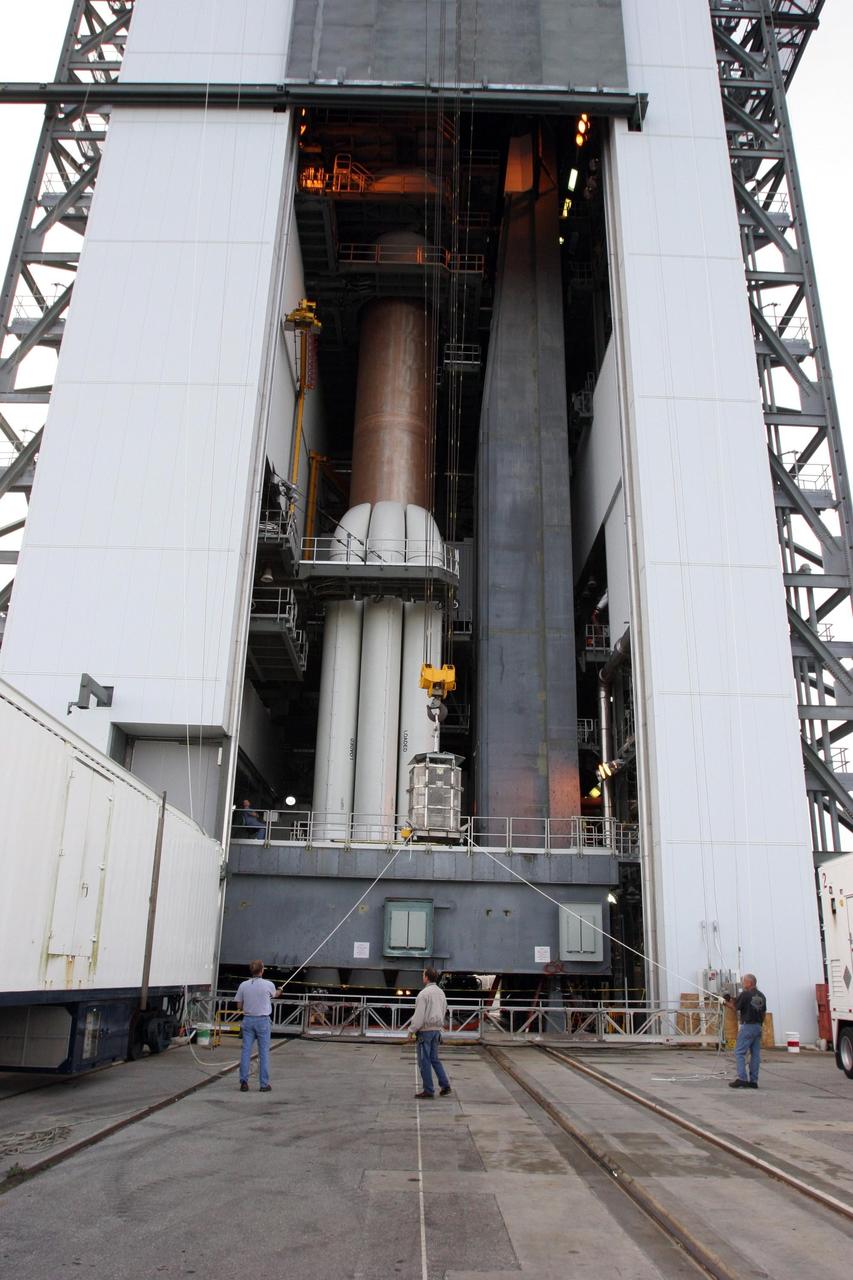
KENNEDY SPACE CENTER, FLA. — On Complex 41 at Cape Canaveral Air Force Station in Florida, workers on the ground oversee the radioisotope thermoelectric generator (RTG) being lifted into the Vertical Integration Facility. The RTG will be installed on the New Horizons spacecraft within the fairing at the top of the Atlas V launch vehicle. Designed and integrated at the Johns Hopkins University Applied Physics Laboratory (APL) in Laurel, Md., New Horizons will launch on a nine-and-a-half-year voyage to Pluto. Typical of RTG-based systems, as on past outer-planet missions, New Horizons does not have a battery for storing power. At the start of the mission, the RTG, which provides power through the natural radioactive decay of plutonium dioxide fuel, will supply approximately 240 watts (at 30 volts of direct current) - the spacecraft’s shunt regulator unit maintains a steady input from the RTG and dissipates power the spacecraft cannot use at a given time. By July 2015 (the earliest Pluto encounter date) that supply decreases to 200 watts at the same voltage, so New Horizons will ease the strain on its limited power source by cycling science instruments during planetary encounters. On Complex 41 at Cape Canaveral Air Force Station in Florida, workers on the ground oversee the radioisotope thermoelectric generator (RTG) being lifted into the Vertical Integration Facility. The RTG will be installed on the New Horizons spacecraft within the fairing at the top of the Atlas V launch vehicle. Designed and integrated at the Johns Hopkins University Applied Physics Laboratory (APL) in Laurel, Md., New Horizons will launch on a nine-and-a-half-year voyage to Pluto. Typical of RTG-based systems, as on past outer-planet missions, New Horizons does not have a battery for storing power. At the start of the mission, the RTG, which provides power through the natural radioactive decay of plutonium dioxide fuel, will supply approximately 240 watts (at 30 volts of direct curren
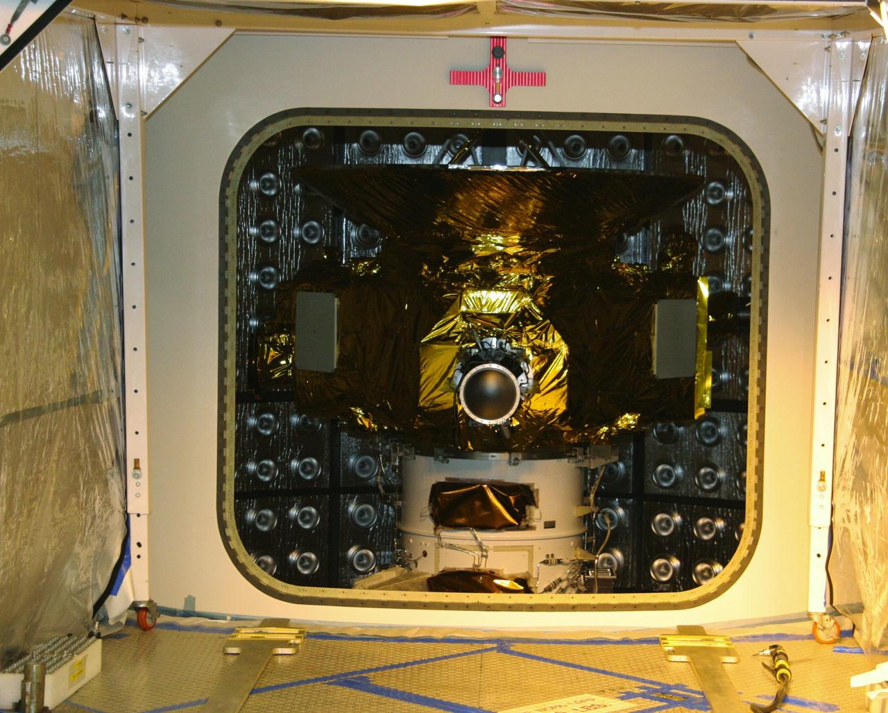
KENNEDY SPACE CENTER, FLA. — On Complex 41 at Cape Canaveral Air Force Station in Florida, the radioisotope thermoelectric generator (RTG) is attached to the New Horizons spacecraft inside the fairing. Designed and integrated at the Johns Hopkins University Applied Physics Laboratory (APL) in Laurel, Md., New Horizons will launch on a nine-and-a-half-year voyage to Pluto. Typical of RTG-based systems, as on past outer-planet missions, New Horizons does not have a battery for storing power. At the start of the mission, the RTG, which provides power through the natural radioactive decay of plutonium dioxide fuel, will supply approximately 240 watts (at 30 volts of direct current) - the spacecraft’s shunt regulator unit maintains a steady input from the RTG and dissipates power the spacecraft cannot use at a given time. By July 2015 (the earliest Pluto encounter date) that supply decreases to 200 watts at the same voltage, so New Horizons will ease the strain on its limited power source by cycling science instruments during planetary encounters. On Complex 41 at Cape Canaveral Air Force Station in Florida, workers on the ground oversee the radioisotope thermoelectric generator (RTG) being lifted into the Vertical Integration Facility. The RTG will be installed on the New Horizons spacecraft within the fairing at the top of the Atlas V launch vehicle. Designed and integrated at the Johns Hopkins University Applied Physics Laboratory (APL) in Laurel, Md., New Horizons will launch on a nine-and-a-half-year voyage to Pluto. Typical of RTG-based systems, as on past outer-planet missions, New Horizons does not have a battery for storing power. At the start of the mission, the RTG, which provides power through the natural radioactive decay of plutonium dioxide fuel, will supply approximately 240 watts (at 30 volts of direct current) - the spacecraft’s shunt regulator unit maintains a steady input from the RTG and dissipates power the spacecraft cannot use at a give
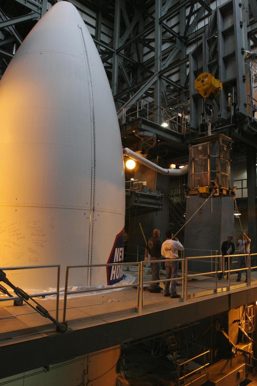
KENNEDY SPACE CENTER, FLA. — On Complex 41 at Cape Canaveral Air Force Station in Florida, the radioisotope thermoelectric generator (RTG) arrives at the upper level of the Vertical Integration Facility. The RTG will be installed on the New Horizons spacecraft encapsulated inside the fairing, at left. Designed and integrated at the Johns Hopkins University Applied Physics Laboratory (APL) in Laurel, Md., New Horizons will launch on a nine-and-a-half-year voyage to Pluto. Typical of RTG-based systems, as on past outer-planet missions, New Horizons does not have a battery for storing power. At the start of the mission, the RTG, which provides power through the natural radioactive decay of plutonium dioxide fuel, will supply approximately 240 watts (at 30 volts of direct current) - the spacecraft’s shunt regulator unit maintains a steady input from the RTG and dissipates power the spacecraft cannot use at a given time. By July 2015 (the earliest Pluto encounter date) that supply decreases to 200 watts at the same voltage, so New Horizons will ease the strain on its limited power source by cycling science instruments during planetary encounters. On Complex 41 at Cape Canaveral Air Force Station in Florida, workers on the ground oversee the radioisotope thermoelectric generator (RTG) being lifted into the Vertical Integration Facility. The RTG will be installed on the New Horizons spacecraft within the fairing at the top of the Atlas V launch vehicle. Designed and integrated at the Johns Hopkins University Applied Physics Laboratory (APL) in Laurel, Md., New Horizons will launch on a nine-and-a-half-year voyage to Pluto. Typical of RTG-based systems, as on past outer-planet missions, New Horizons does not have a battery for storing power. At the start of the mission, the RTG, which provides power through the natural radioactive decay of plutonium dioxide fuel, will supply approximately 240 watts (at 30 volts of direct current) - the spacecraft’s shunt reg
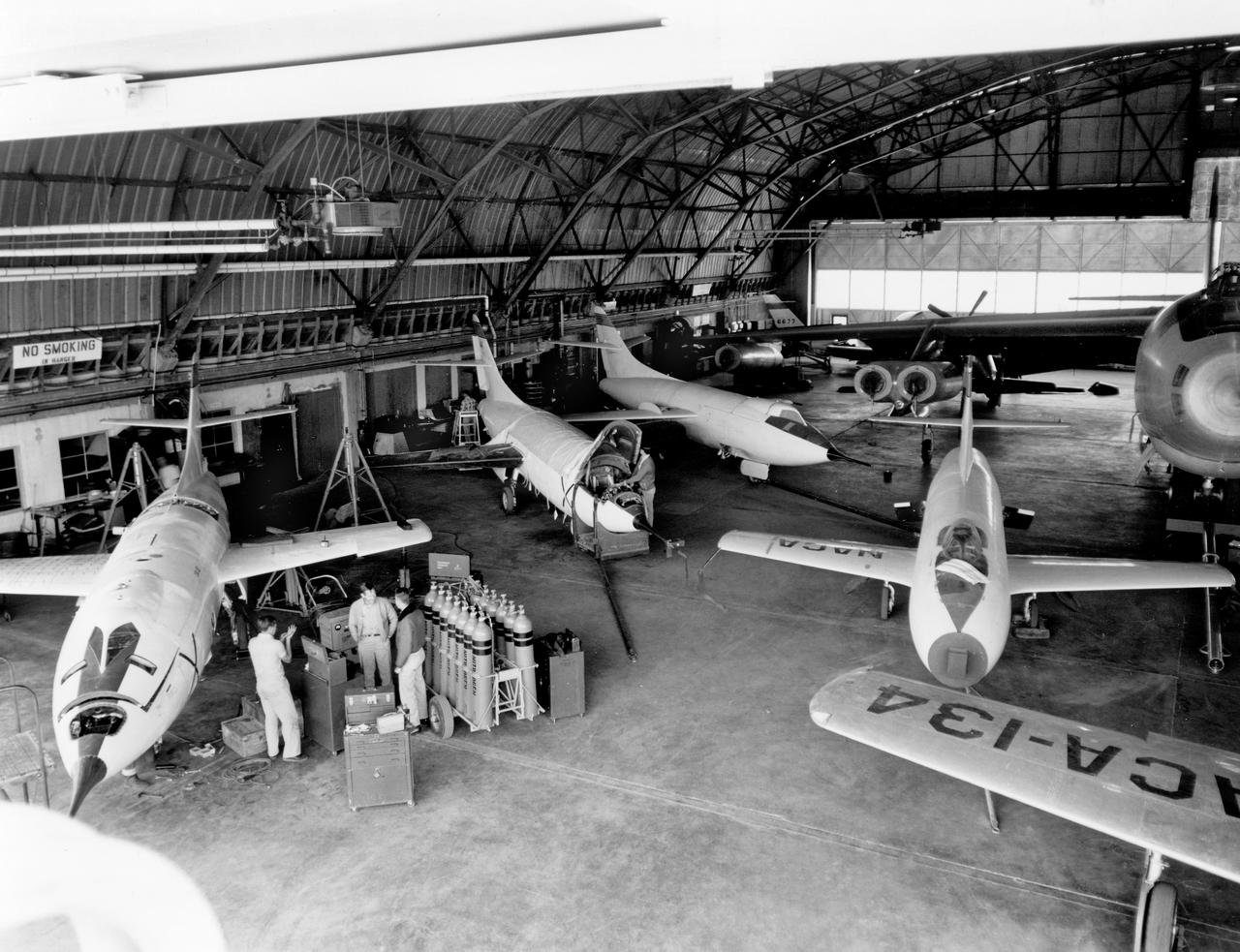
The aircraft in this 1953 photo of the National Advisory Committee for Aeronautics (NACA) hangar at South Base of Edwards Air Force Base showed the wide range of research activities being undertaken. On the left side of the hangar are the three D-558-2 research aircraft. These were designed to test swept wings at supersonic speeds approaching Mach 2. The front D-558-2 is the third built (NACA 145/Navy 37975). It has been modified with a leading-edge chord extension. This was one of a number of wing modifications, using different configurations of slats and/or wing fences, to ease the airplane's tendency to pitch-up. NACA 145 had both a jet and a rocket engine. The middle aircraft is NACA 144 (Navy 37974), the second built. It was all-rocket powered, and Scott Crossfield made the first Mach 2 flight in this aircraft on November 20, 1953. The aircraft in the back is D-558-2 number 1. NACA 143 (Navy 37973) was also carried both a jet and a rocket engine in 1953. It had been used for the Douglas contractor flights, then was turned over to the NACA. The aircraft was not converted to all-rocket power until June 1954. It made only a single NACA flight before NACA's D-558-2 program ended in 1956. Beside the three D-558-2s is the third D-558-1. Unlike the supersonic D-558-2s, it was designed for flight research at transonic speeds, up to Mach 1. The D-558-1 was jet-powered, and took off from the ground. The D-558-1's handling was poor as it approached Mach 1. Given the designation NACA 142 (Navy 37972), it made a total of 78 research flights, with the last in June 1953. In the back of the hangar is the X-4 (Air Force 46-677). This was a Northrop-built research aircraft which tested a swept wing design without horizontal stabilizers. The aircraft proved unstable in flight at speeds above Mach 0.88. The aircraft showed combined pitching, rolling, and yawing motions, and the design was considered unsuitable. The aircraft, the second X-4 built, was then used as a pilot traine
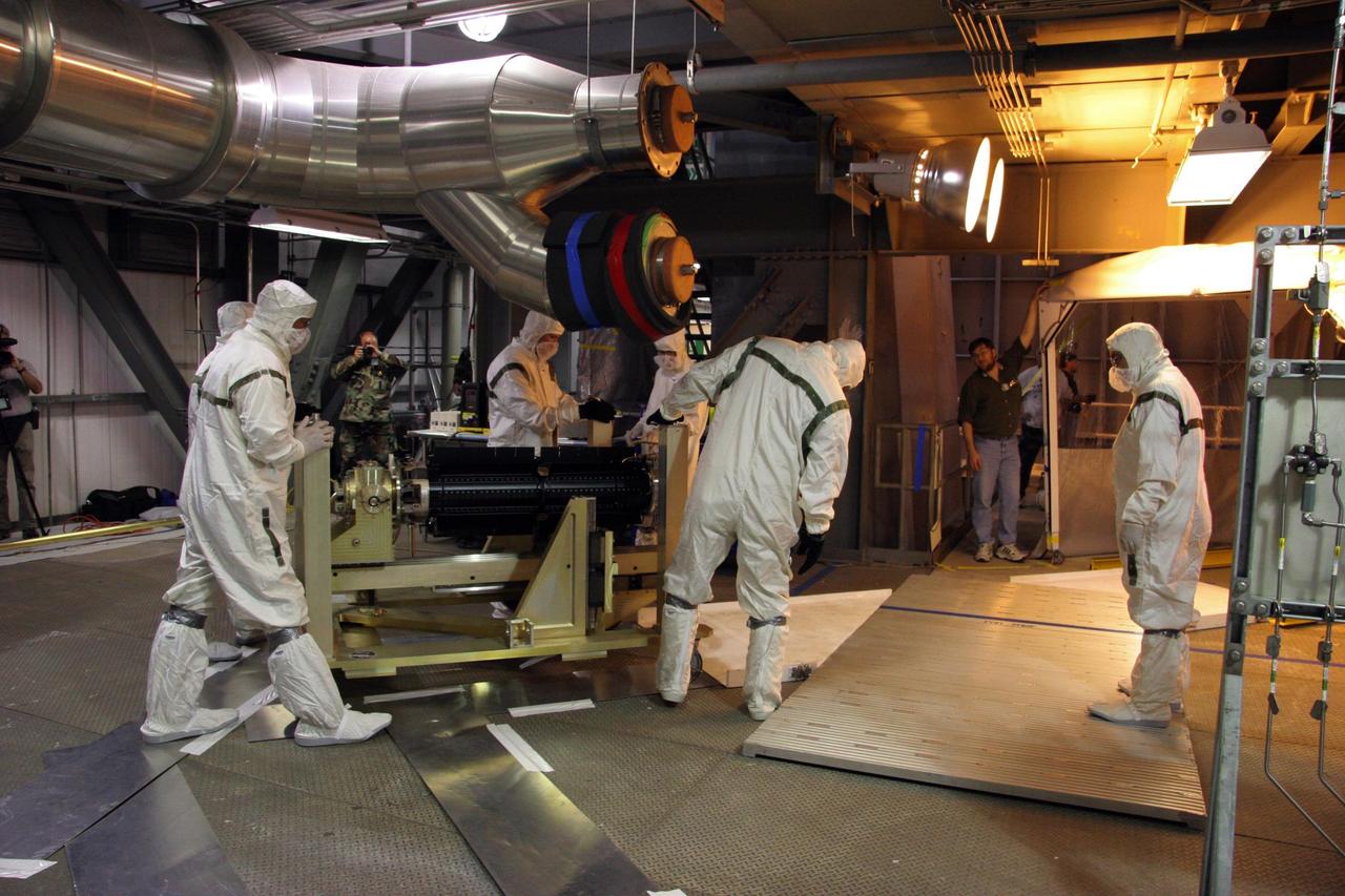
KENNEDY SPACE CENTER, FLA. — On Complex 41 at Cape Canaveral Air Force Station in Florida, workers move the radioisotope thermoelectric generator (RTG). The generator will be installed on the New Horizons spacecraft encapsulated inside the fairing. Designed and integrated at the Johns Hopkins University Applied Physics Laboratory (APL) in Laurel, Md., New Horizons will launch on a nine-and-a-half-year voyage to Pluto. Typical of RTG-based systems, as on past outer-planet missions, New Horizons does not have a battery for storing power. At the start of the mission, the RTG, which provides power through the natural radioactive decay of plutonium dioxide fuel, will supply approximately 240 watts (at 30 volts of direct current) - the spacecraft’s shunt regulator unit maintains a steady input from the RTG and dissipates power the spacecraft cannot use at a given time. By July 2015 (the earliest Pluto encounter date) that supply decreases to 200 watts at the same voltage, so New Horizons will ease the strain on its limited power source by cycling science instruments during planetary encounters. On Complex 41 at Cape Canaveral Air Force Station in Florida, workers on the ground oversee the radioisotope thermoelectric generator (RTG) being lifted into the Vertical Integration Facility. The RTG will be installed on the New Horizons spacecraft within the fairing at the top of the Atlas V launch vehicle. Designed and integrated at the Johns Hopkins University Applied Physics Laboratory (APL) in Laurel, Md., New Horizons will launch on a nine-and-a-half-year voyage to Pluto. Typical of RTG-based systems, as on past outer-planet missions, New Horizons does not have a battery for storing power. At the start of the mission, the RTG, which provides power through the natural radioactive decay of plutonium dioxide fuel, will supply approximately 240 watts (at 30 volts of direct current) - the spacecraft’s shunt regulator unit maintains a steady input from the RTG and diss
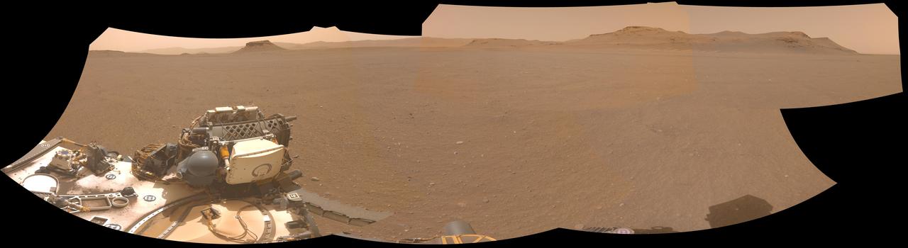
NASA's Perseverance Mars rover used one of its navigation cameras to take this panorama of a proposed landing site for the Mars Sample Return lander. The lander would collect rock and sediment samples that Perseverance has taken and would also serve as the launch platform for a Mars Ascent Vehicle that would blast off from Mars, delivering the samples to an orbiter as part of their journey to Earth for intensive study. Choosing an area that lacks large rocks (especially those over 7 1/2 inches, or 19 centimeters, in diameter), sand dunes, and steeply angled terrain would go a long way toward easing the path for an MSR recovery vehicle to efficiently grab tubes before heading to the lander. This panorama is made up of five images taken on April 14, 2022 (the 409th Martian day, or sol, of the mission) and stitched together back on Earth. The color has been adjusted to match the lighting conditions as the human eye would perceive them on Earth. A key objective for Perseverance's mission on Mars is astrobiology, including the search for signs of ancient microbial life. The rover will characterize the planet's geology and past climate, pave the way for human exploration of the Red Planet, and be the first mission to collect and cache Martian rock and regolith (broken rock and dust). Subsequent NASA missions, in cooperation with ESA (European Space Agency), would send spacecraft to Mars to collect these sealed samples from the surface and return them to Earth for in-depth analysis. The Mars 2020 Perseverance mission is part of NASA's Moon to Mars exploration approach, which includes Artemis missions to the Moon that will help prepare for human exploration of the Red Planet. https://photojournal.jpl.nasa.gov/catalog/PIA25406
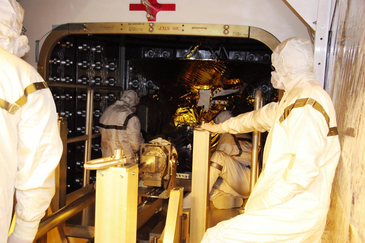
KENNEDY SPACE CENTER, FLA. — On Complex 41 at Cape Canaveral Air Force Station in Florida, workers move the radioisotope thermoelectric generator (RTG) into an area of the fairing containing the New Horizons spacecraft, to which it will be attached. Designed and integrated at the Johns Hopkins University Applied Physics Laboratory (APL) in Laurel, Md., New Horizons will launch on a nine-and-a-half-year voyage to Pluto. Typical of RTG-based systems, as on past outer-planet missions, New Horizons does not have a battery for storing power. At the start of the mission, the RTG, which provides power through the natural radioactive decay of plutonium dioxide fuel, will supply approximately 240 watts (at 30 volts of direct current) - the spacecraft’s shunt regulator unit maintains a steady input from the RTG and dissipates power the spacecraft cannot use at a given time. By July 2015 (the earliest Pluto encounter date) that supply decreases to 200 watts at the same voltage, so New Horizons will ease the strain on its limited power source by cycling science instruments during planetary encounters. On Complex 41 at Cape Canaveral Air Force Station in Florida, workers on the ground oversee the radioisotope thermoelectric generator (RTG) being lifted into the Vertical Integration Facility. The RTG will be installed on the New Horizons spacecraft within the fairing at the top of the Atlas V launch vehicle. Designed and integrated at the Johns Hopkins University Applied Physics Laboratory (APL) in Laurel, Md., New Horizons will launch on a nine-and-a-half-year voyage to Pluto. Typical of RTG-based systems, as on past outer-planet missions, New Horizons does not have a battery for storing power. At the start of the mission, the RTG, which provides power through the natural radioactive decay of plutonium dioxide fuel, will supply approximately 240 watts (at 30 volts of direct current) - the spacecraft’s shunt regulator unit maintains a steady input from the RTG and diss
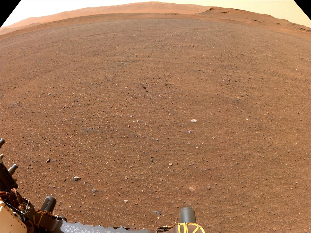
NASA's Perseverance Mars rover used one of its navigation cameras to take this image of flat terrain in Jezero Crater. This is one possible site that NASA may consider for a Mars Sample Return lander that would collect Perseverance's samples of Mars rock and sediment in the future. The lander would serve as the launch platform for a Mars Ascent Vehicle that would blast off from Mars, delivering the samples to an orbiter as part of their journey to Earth for intensive study. Choosing an area that lacks large rocks (especially those over 7 1/2 inches, or 19 centimeters, in diameter), sand dunes, and steeply angled terrain would go a long way toward easing the path for an MSR recovery vehicle to efficiently grab tubes before heading to the lander. A key objective for Perseverance's mission on Mars is astrobiology, including the search for signs of ancient microbial life. The rover will characterize the planet's geology and past climate, pave the way for human exploration of the Red Planet, and be the first mission to collect and cache Martian rock and regolith (broken rock and dust). Subsequent NASA missions, in cooperation with ESA (European Space Agency), would send spacecraft to Mars to collect these sealed samples from the surface and return them to Earth for in-depth analysis. The Mars 2020 Perseverance mission is part of NASA's Moon to Mars exploration approach, which includes Artemis missions to the Moon that will help prepare for human exploration of the Red Planet. https://photojournal.jpl.nasa.gov/catalog/PIA25370

Climbing "Vera Rubin Ridge" provided NASA's Curiosity Mars rover this sweeping vista of the interior and rim of Gale Crater, including much of the rover's route during its first five-and-a-half years on Mars and features up to about 50 miles (85 kilometers) away. The scene spans from southwest on the left to northeast on the right, combining 16 side-by-side images taken by the left-eye, wider-angle-lens camera of Curiosity's Mast Camera (Mastcam). It has been white-balanced so the colors of the rock materials resemble how they would appear under daytime lighting conditions on Earth. The component images were taken on Oct. 25, 2017, during the 1,856th Martian day, or sol, of the rover's work on Mars. At that point, Curiosity had gained 1,073 feet (327 meters) in elevation and driven 10.95 miles (17.63 kilometers) from its landing site. Mount Sharp stands about 3 miles (5 kilometers) high in the middle of Gale Crater, which spans 96 miles (154 kilometers) in diameter. Vera Rubin Ridge is on the northwestern flank of lower Mount Sharp. The foreground of this panorama shows portions of lower Mount Sharp. The middle distance shows the floor of Gale Crater. Most of the horizon is formed by the crater's rim. The top of the rim is about 1.2 miles (2 kilometers) higher than the rover's position. On the horizon near the center of the image is a glimpse outside of Gale Crater, to a peak about 50 miles (85 kilometers) from the rover. An annotated version, Figure 1, indicates the rover's approximate path since its 2012 landing, identifies some of the sites it has investigated along the way, such as "Yellowknife Bay," "The Kimberley," "Namib Dune" and "Murray Buttes"; and points out other geological features visible in the scene, such as the channel of Peace Vallis, an ancient streambed descending from the crater rim. The relative positions of the labeled features are also mapped on an accompanying orbital view in PIA22208, with two areas color-coded for ease of matching them in the annotated panorama and the orbital view. Figure 2 is a version with a white-line box indicating the smaller area covered in a more-detailed vista (see PIA22209) taken from this same rover location by Mastcam's right-eye, telephoto-lens camera. It also includes three scale bars: of 50 meters (164 feet) at a distance of 1,170 meters (1,280 yards) near the base of Mount Sharp; of 1,000 meters (1,094 yards) at a distance of about 23.4 kilometers (14.5 miles) near the base of the crater wall; and of 2 kilometers (1.2 miles) at a distance of about 31.5 kilometers (19.6 miles) at the crest of the rim. Annotated images are available at https://photojournal.jpl.nasa.gov/catalog/PIA22210

It drains a watershed that spans eight countries and nearly 1.6 million square kilometers 600,000 square miles. The Zambezi also Zambeze is the fourth largest river in Africa, and the largest east-flowing waterway. The Operational Land Imager on the Landsat 8 satellite acquired this natural-color image of the Zambezi Delta on August 29, 2013. Sandbars and barrier spits stretch across the mouths of the delta, and suspended sediment extends tens of kilometers out into the sea. The sandy outflow turns the coastal waters to a milky blue-green compared to the deep blue of open water in the Indian Ocean. The Zambezi Delta includes 230 kilometers of coastline fronting 18,000 square kilometers (7,00 square miles) of swamps, floodplains, and even savannahs (inland). The area has long been prized by subsistence fishermen and farmers, who find fertile ground for crops like sugar and fertile waters for prawns and fish. Two species of endangered cranes and one of the largest concentration of buffalo in Africa -- among many other species of wildlife -- have found a haven in this internationally recognized wetland. However, the past six decades have brought great changes to the Zambezi Delta, which used to pour more water and sediment off of the continent. Hydropower dams upstream-most prominently, the Kariba and the Cahora Bassa-greatly reduce river flows during the wet season; they also trap sediments that would otherwise flow downstream. The result has been less water reaching the delta and the floodplains, which rely on pulses of nutrients and sediments from annual (and mostly benign) natural flooding. The change in the flow of the river affects freshwater availability and quality in the delta. Strong flows push fresh water further out into the sea and naturally keep most of a delta full of fresh (or mostly fresh) water. When that fresh flow eases, the wetlands become drier and more prone to fire. Salt water from the Indian Ocean also can penetrate further into the marsh, upsetting the ecological balance for aquatic plant and animal species. Researchers have found that the freshwater table in the delta has dropped as much as five meters in the 50 years since dams were placed on the river. Less river flow also affects the shape and extent of the delta. Today there is less sediment replenishing the marshes and beaches as they are scoured by ocean waves and tides. "What strikes me in this image is the suspended sediment offshore," said Liviu Giosan, a delta geologist at the Woods Hole Oceanographic Institution. "Sediment appears to be transferred from the delta offshore in plumes that not only originate in active river mouths but also from deactivated former mouths, now tidal channels. This shows the power of tidal scouring contributing to the slow but relentless erosion of the delta." http://photojournal.jpl.nasa.gov/catalog/PIA18155
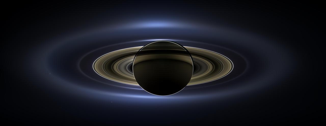
On July 19, 2013, in an event celebrated the world over, NASA's Cassini spacecraft slipped into Saturn's shadow and turned to image the planet, seven of its moons, its inner rings -- and, in the background, our home planet, Earth. With the sun's powerful and potentially damaging rays eclipsed by Saturn itself, Cassini's onboard cameras were able to take advantage of this unique viewing geometry. They acquired a panoramic mosaic of the Saturn system that allows scientists to see details in the rings and throughout the system as they are backlit by the sun. This mosaic is special as it marks the third time our home planet was imaged from the outer solar system; the second time it was imaged by Cassini from Saturn's orbit; and the first time ever that inhabitants of Earth were made aware in advance that their photo would be taken from such a great distance. With both Cassini's wide-angle and narrow-angle cameras aimed at Saturn, Cassini was able to capture 323 images in just over four hours. This final mosaic uses 141 of those wide-angle images. Images taken using the red, green and blue spectral filters of the wide-angle camera were combined and mosaicked together to create this natural-color view. A brightened version with contrast and color enhanced (Figure 1), a version with just the planets annotated (Figure 2), and an annotated version (Figure 3) are shown above. This image spans about 404,880 miles (651,591 kilometers) across. The outermost ring shown here is Saturn's E ring, the core of which is situated about 149,000 miles (240,000 kilometers) from Saturn. The geysers erupting from the south polar terrain of the moon Enceladus supply the fine icy particles that comprise the E ring; diffraction by sunlight gives the ring its blue color. Enceladus (313 miles, or 504 kilometers, across) and the extended plume formed by its jets are visible, embedded in the E ring on the left side of the mosaic. At the 12 o'clock position and a bit inward from the E ring lies the barely discernible ring created by the tiny, Cassini-discovered moon, Pallene (3 miles, or 4 kilometers, across). (For more on structures like Pallene's ring, see PIA08328). The next narrow and easily seen ring inward is the G ring. Interior to the G ring, near the 11 o'clock position, one can barely see the more diffuse ring created by the co-orbital moons, Janus (111 miles, or 179 kilometers, across) and Epimetheus (70 miles, or 113 kilometers, across). Farther inward, we see the very bright F ring closely encircling the main rings of Saturn. Following the outermost E ring counter-clockwise from Enceladus, the moon Tethys (662 miles, or 1,066 kilometers, across) appears as a large yellow orb just outside of the E ring. Tethys is positioned on the illuminated side of Saturn; its icy surface is shining brightly from yellow sunlight reflected by Saturn. Continuing to about the 2 o'clock position is a dark pixel just outside of the G ring; this dark pixel is Saturn's Death Star moon, Mimas (246 miles, or 396 kilometers, across). Mimas appears, upon close inspection, as a very thin crescent because Cassini is looking mostly at its non-illuminated face. The moons Prometheus, Pandora, Janus and Epimetheus are also visible in the mosaic near Saturn's bright narrow F ring. Prometheus (53 miles, or 86 kilometers, across) is visible as a faint black dot just inside the F ring and at the 9 o'clock position. On the opposite side of the rings, just outside the F ring, Pandora (50 miles, or 81 kilometers, across) can be seen as a bright white dot. Pandora and Prometheus are shepherd moons and gravitational interactions between the ring and the moons keep the F ring narrowly confined. At the 11 o'clock position in between the F ring and the G ring, Janus (111 miles, or 179 kilometers, across) appears as a faint black dot. Janus and Prometheus are dark for the same reason Mimas is mostly dark: we are looking at their non-illuminated sides in this mosaic. Midway between the F ring and the G ring, at about the 8 o'clock position, is a single bright pixel, Epimetheus. Looking more closely at Enceladus, Mimas and Tethys, especially in the brightened version of the mosaic, one can see these moons casting shadows through the E ring like a telephone pole might cast a shadow through a fog. In the non-brightened version of the mosaic, one can see bright clumps of ring material orbiting within the Encke gap near the outer edge of the main rings and immediately to the lower left of the globe of Saturn. Also, in the dark B ring within the main rings, at the 9 o'clock position, one can see the faint outlines of two spoke features, first sighted by NASA's Voyager spacecraft in the early 1980s and extensively studied by Cassini. Finally, in the lower right of the mosaic, in between the bright blue E ring and the faint but defined G ring, is the pale blue dot of our planet, Earth. Look closely and you can see the moon protruding from the Earth's lower right. (For a higher resolution view of the Earth and moon taken during this campaign, see PIA14949.) Earth's twin, Venus, appears as a bright white dot in the upper left quadrant of the mosaic, also between the G and E rings. Mars also appears as a faint red dot embedded in the outer edge of the E ring, above and to the left of Venus. For ease of visibility, Earth, Venus, Mars, Enceladus, Epimetheus and Pandora were all brightened by a factor of eight and a half relative to Saturn. Tethys was brightened by a factor of four. In total, 809 background stars are visible and were brightened by a factor ranging from six, for the brightest stars, to 16, for the faintest. The faint outer rings (from the G ring to the E ring) were also brightened relative to the already bright main rings by factors ranging from two to eight, with the lower-phase-angle (and therefore fainter) regions of these rings brightened the most. The brightened version of the mosaic was further brightened and contrast-enhanced all over to accommodate print applications and a wide range of computer-screen viewing conditions. Some ring features -- such as full rings traced out by tiny moons -- do not appear in this version of the mosaic because they require extreme computer enhancement, which would adversely affect the rest of the mosaic. This version was processed for balance and beauty. This view looks toward the unlit side of the rings from about 17 degrees below the ring plane. Cassini was approximately 746,000 miles (1.2 million kilometers) from Saturn when the images in this mosaic were taken. Image scale on Saturn is about 45 miles (72 kilometers) per pixel. This mosaic was made from pictures taken over a span of more than four hours while the planets, moons and stars were all moving relative to Cassini. Thus, due to spacecraft motion, these objects in the locations shown here were not in these specific places over the entire duration of the imaging campaign. Note also that Venus appears far from Earth, as does Mars, because they were on the opposite side of the sun from Earth. http://photojournal.jpl.nasa.gov/catalog/PIA17172