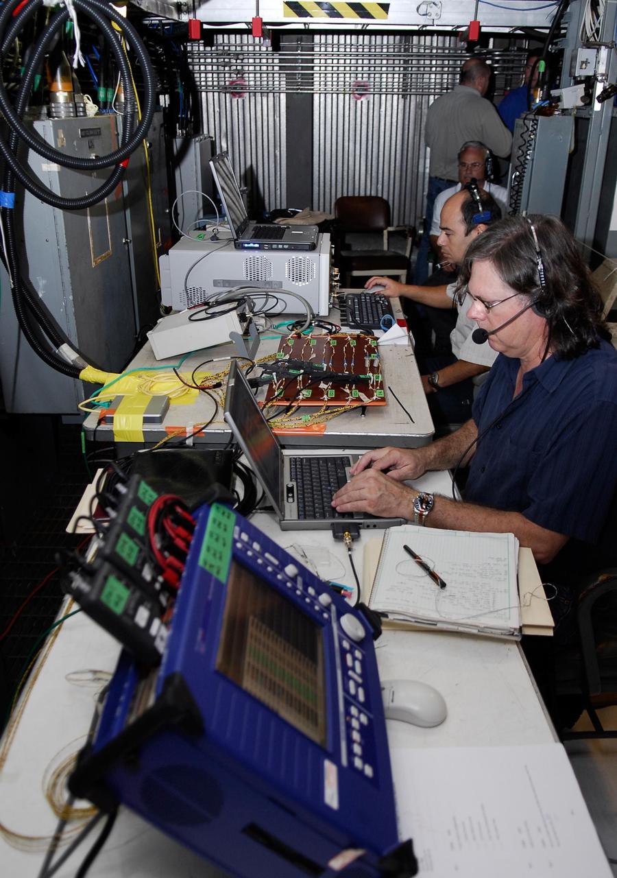
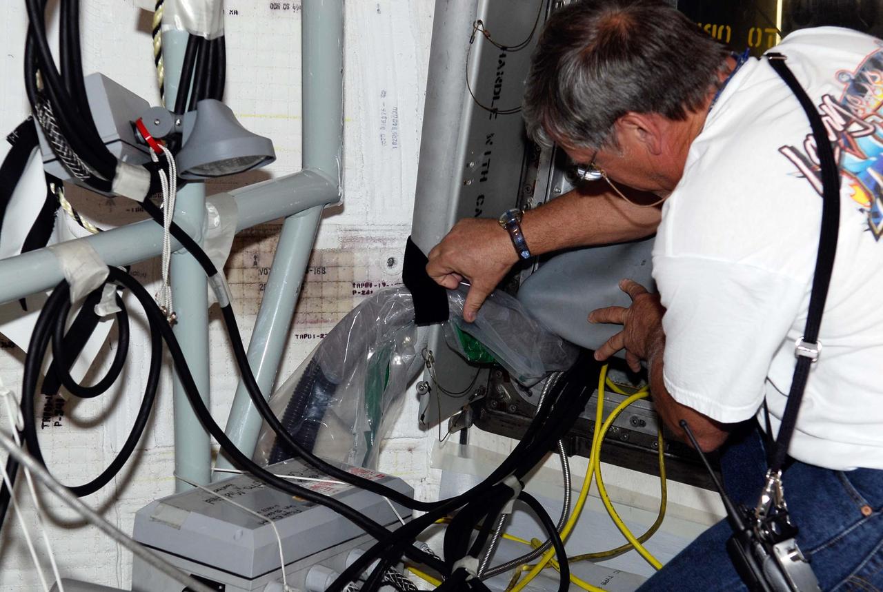
KENNEDY SPACE CENTER, FLA. -- On Launch Pad 39A at NASA's Kennedy Space Center, the wiring is checked and validated before the tanking test on space shuttle Atlantis' external tank set for Dec. 18. The test wiring has been spliced into an electrical harness in the aft main engine compartment connected with the engine cut-off, or ECO, sensor system. The attached wiring leads to the interior of the mobile launcher platform where the time domain reflectometry, or TDR, test equipment is located. Photo credit: NASA/Kim Shiflett
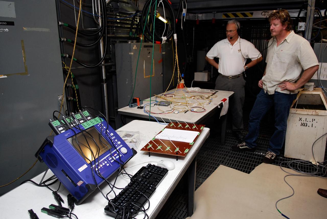
KENNEDY SPACE CENTER, FLA. -- On Launch Pad 39A, technicians overlook wires and monitoring equipment that will be used to validate the circuit on the test wiring from the electrical harness in space shuttle Atlantis' aft main engine compartment connected with the engine cut-off system. The test wiring leads from the tail mast on the mobile launcher platform to the interior where the Time Domain Reflectometry, or TDR, test equipment will be located to test the sensor system. Photo credit: NASA/Kim Shiflett
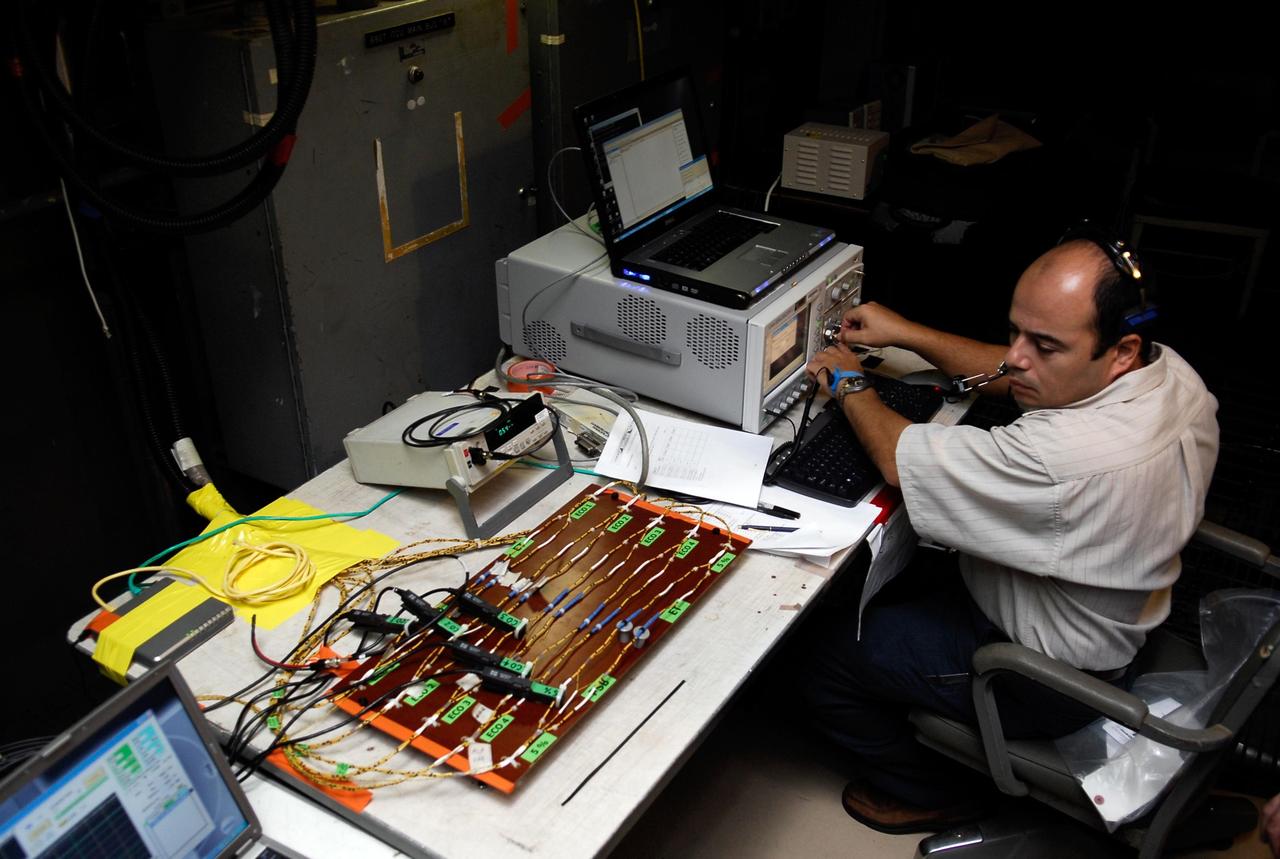
KENNEDY SPACE CENTER, FLA. -- On Launch Pad 39A at NASA's Kennedy Space Center, the wiring is checked and validated before the tanking test on space shuttle Atlantis' external tank set for Dec. 18. The test wiring has been spliced into an electrical harness in the aft main engine compartment connected with the engine cut-off, or ECO, sensor system. The attached wiring leads to the interior of the mobile launcher platform where the time domain reflectometry, or TDR, test equipment is located. Photo credit: NASA/Kim Shiflett

KENNEDY SPACE CENTER, FLA. -- On Launch Pad 39A at NASA's Kennedy Space Center, the wiring is checked and validated before the tanking test on space shuttle Atlantis' external tank set for Dec. 18. The test wiring has been spliced into an electrical harness in the aft main engine compartment connected with the engine cut-off, or ECO, sensor system. The attached wiring leads to the interior of the mobile launcher platform where the time domain reflectometry, or TDR, test equipment is located. Photo credit: NASA/Kim Shiflett
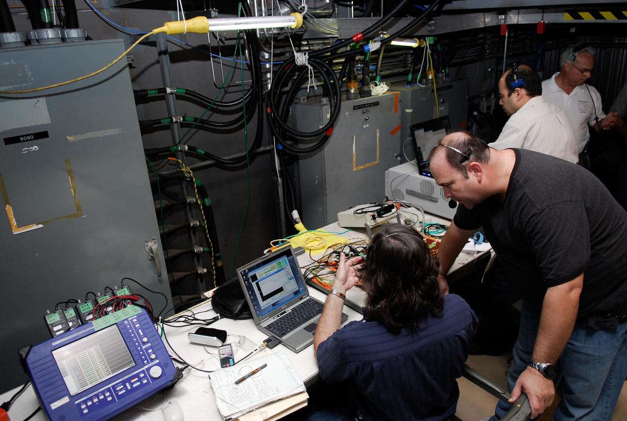
KENNEDY SPACE CENTER, FLA. -- On Launch Pad 39A at NASA's Kennedy Space Center, the wiring is checked and validated before the tanking test on space shuttle Atlantis' external tank set for Dec. 18. The test wiring has been spliced into an electrical harness in the aft main engine compartment connected with the engine cut-off, or ECO, sensor system. The attached wiring leads to the interior of the mobile launcher platform where the time domain reflectometry, or TDR, test equipment is located. Photo credit: NASA/Kim Shiflett
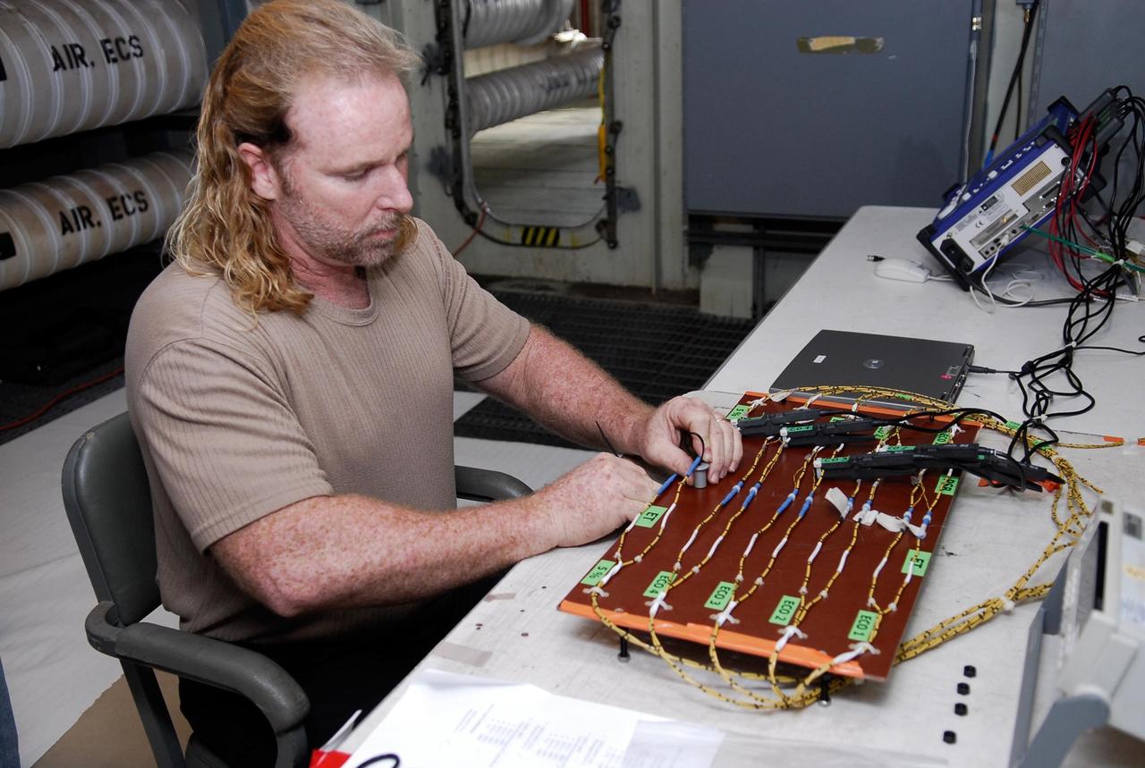
KENNEDY SPACE CENTER, FLA. -- On Launch Pad 39A at NASA's Kennedy Space Center, a technician sets up wiring for the tanking test on space shuttle Atlantis' external tank set for Dec. 18. The test wiring has been spliced into an electrical harness in the aft main engine compartment connected with the engine cut-off, or ECO, sensor system. The attached wiring leads to the interior of the mobile launcher platform where the time domain reflectometry, or TDR, test equipment is located. Photo credit: NASA/Kim Shiflett
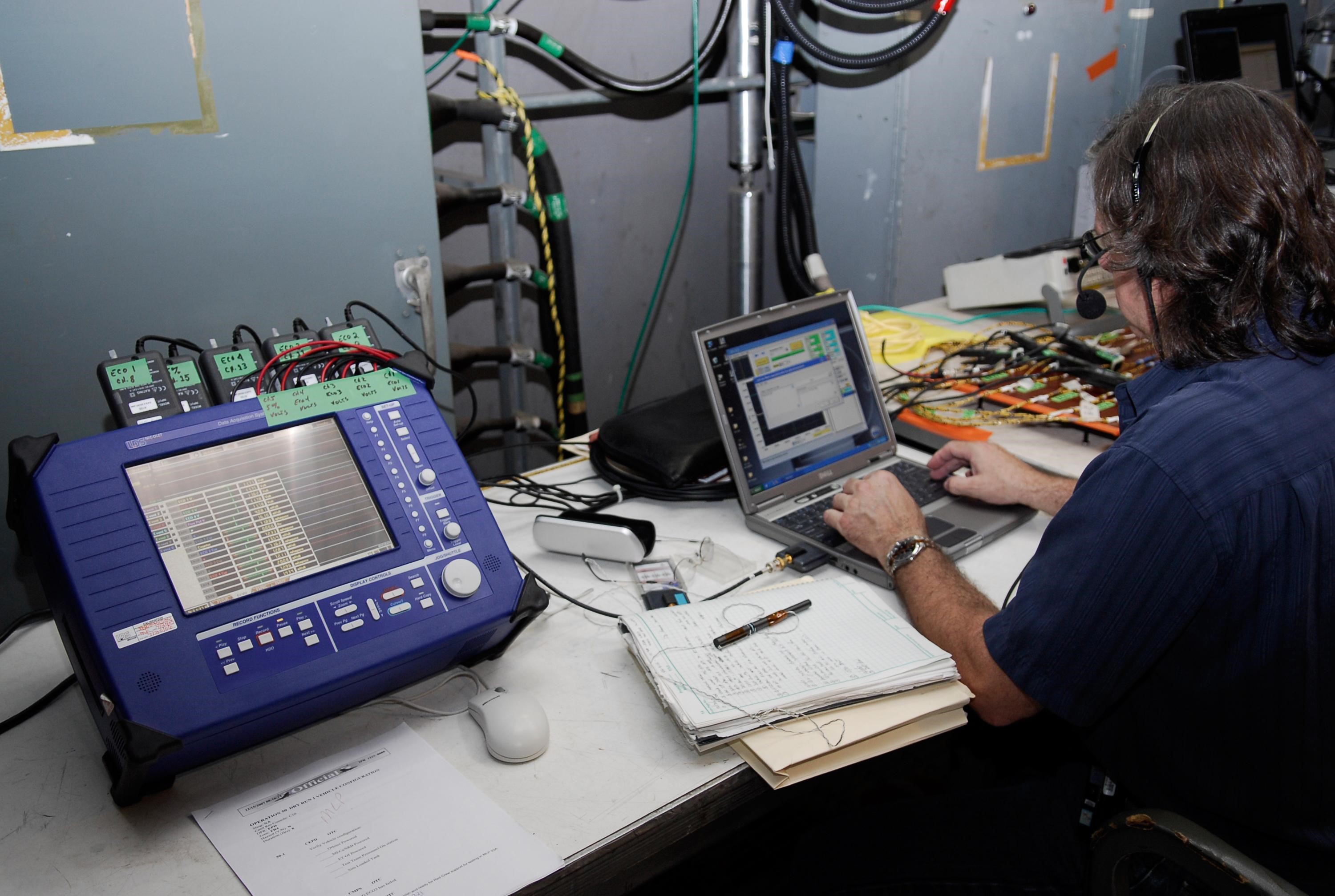
KENNEDY SPACE CENTER, FLA. -- On Launch Pad 39A at NASA's Kennedy Space Center, the wiring is checked and validated before the tanking test on space shuttle Atlantis' external tank set for Dec. 18. The test wiring has been spliced into an electrical harness in the aft main engine compartment connected with the engine cut-off, or ECO, sensor system. The attached wiring leads to the interior of the mobile launcher platform where the time domain reflectometry, or TDR, test equipment is located. Photo credit: NASA/Kim Shiflett
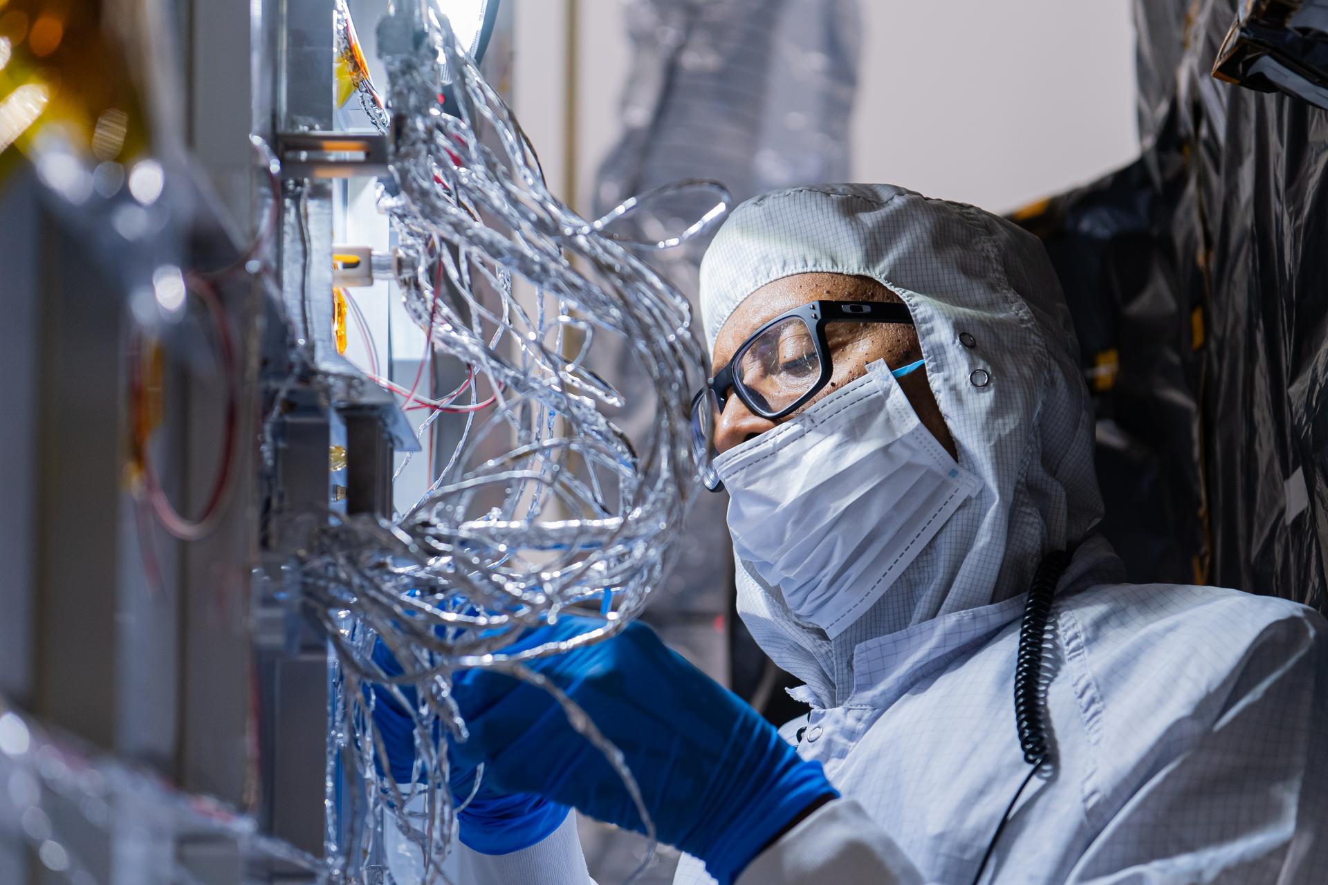
OSAM-1 Electrical Engineer Gregory Griffin tapes hardware on the underside of the OSAM-1 Servicing Payload inside cleanroom at Goddard Space Flight Center, Greenbelt Md., Aug 19, 2024. This photo has been reviewed by the Export Control Office, project Management, and Maxar release authority and is released for public view. NASA/Mike Guinto
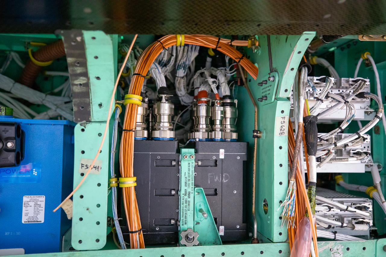
This is a closeup view of the inner workings of the X-59 aircraft. Visible are one the plane’s three lithium-ion batteries (blue box), electrical power system and other wiring components including the vehicle management systems computers (two black boxes) and the white wirings which assist in providing the power that is needed for the aircraft to function in flight. All of these components are essential to maintaining and monitoring the X-59 once it takes to the skies. The X-59 is the centerpiece of the Quesst mission which plans to help enable commercial supersonic air travel over land.
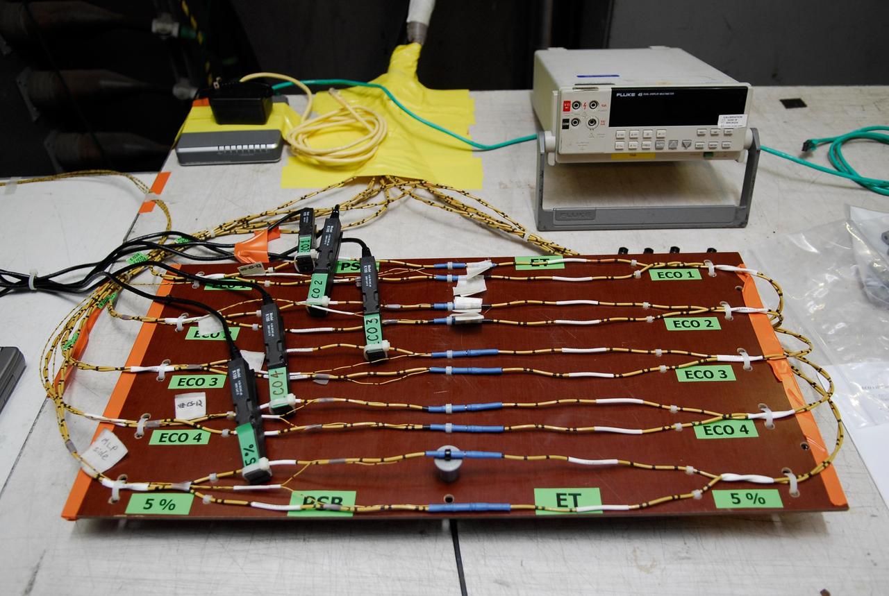
KENNEDY SPACE CENTER, FLA. -- On Launch Pad 39A at NASA's Kennedy Space Center, a wiring board has been set up for the tanking test on space shuttle Atlantis' external tank set for Dec. 18. The test wiring has been spliced into an electrical harness in the aft main engine compartment connected with the engine cut-off, or ECO, sensor system. The attached wiring leads to the interior of the mobile launcher platform where the time domain reflectometry, or TDR, test equipment is located. Photo credit: NASA/Kim Shiflett
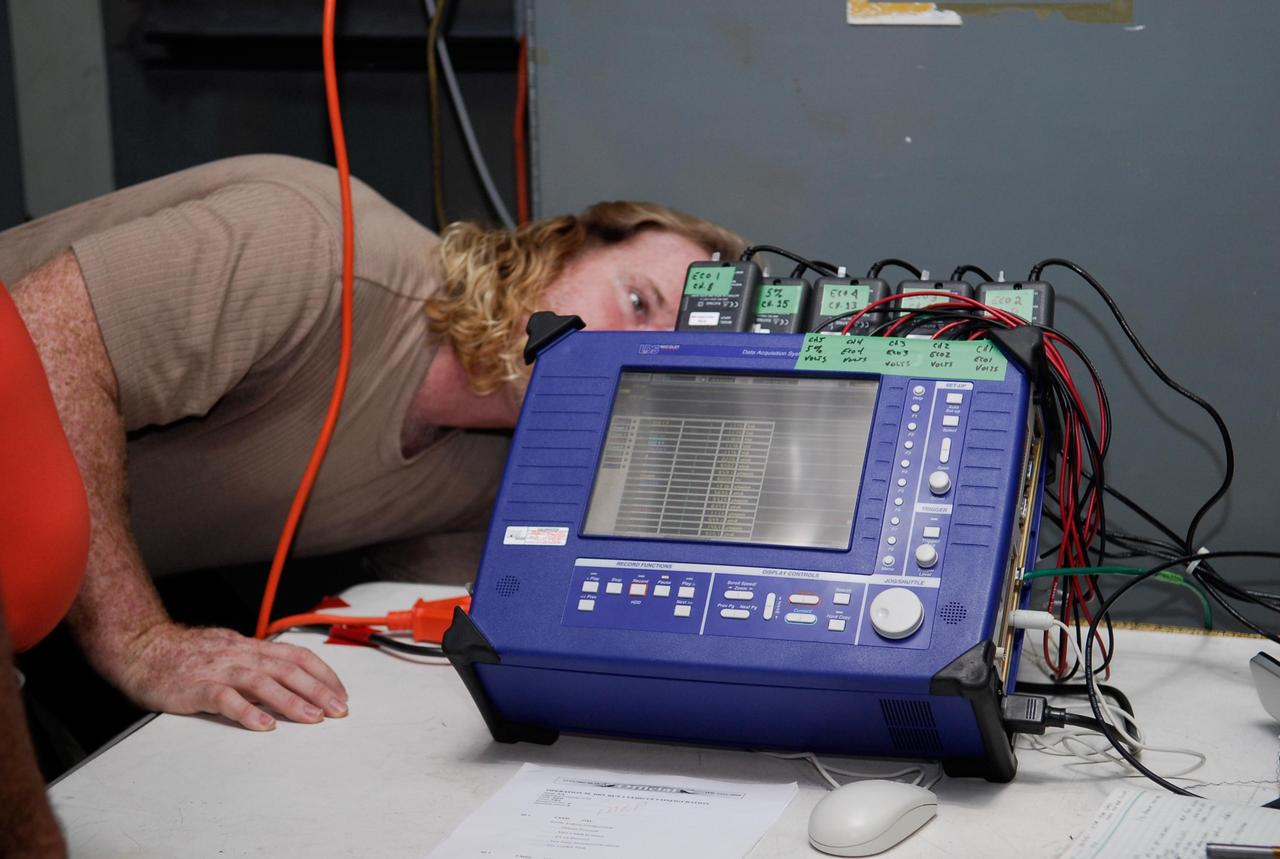
KENNEDY SPACE CENTER, FLA. -- On Launch Pad 39A at NASA's Kennedy Space Center, a technician checks the blue monitor that will be used to validate the circuit on test wiring during the tanking test on space shuttle Atlantis' external tank. The test wiring has been spliced into an electrical harness in the aft main engine compartment connected with the engine cut-off, or ECO, sensor system. The attached wiring leads to the interior of the mobile launcher platform where the time domain reflectometry, or TDR, test equipment is located. Photo credit: NASA/Kim Shiflett
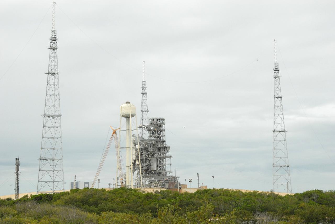
CAPE CANAVERAL, Fla. – On Launch Pad 39B at NASA's Kennedy Space Center in Florida, catenary wires are being suspended from the lighting masts on the lightning towers. The catenary wire system under development for the Constellation Program’s next-generation vehicles will significantly increase the shielding level, providing better protection, and further separate the electrical current from vital launch hardware. The system will help avoid delays to the launch schedule by collecting more information on the strike for analysis by launch managers. Photo credit: NASA/Jack Pfaller
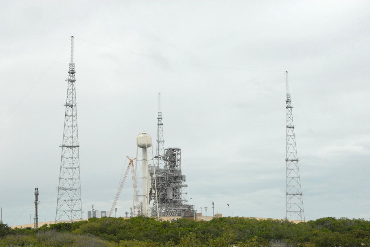
CAPE CANAVERAL, Fla. – On Launch Pad 39B at NASA's Kennedy Space Center in Florida, catenary wires are being suspended from the lighting masts on the lightning towers. The catenary wire system under development for the Constellation Program’s next-generation vehicles will significantly increase the shielding level, providing better protection, and further separate the electrical current from vital launch hardware. The system will help avoid delays to the launch schedule by collecting more information on the strike for analysis by launch managers. Photo credit: NASA/Jack Pfaller
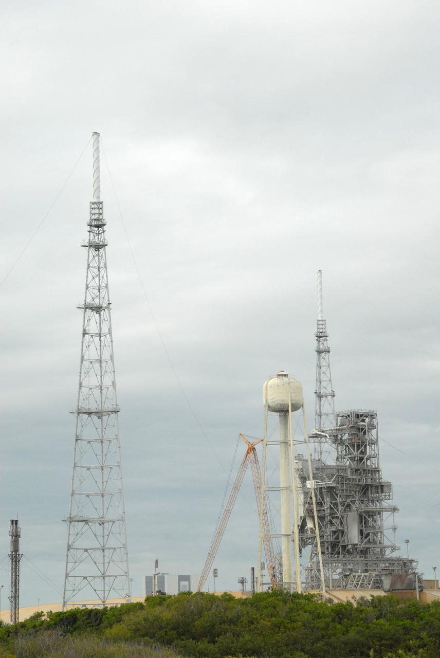
CAPE CANAVERAL, Fla. – On Launch Pad 39B at NASA's Kennedy Space Center in Florida, catenary wires are being suspended from the lighting masts on the lightning towers. The catenary wire system under development for the Constellation Program’s next-generation vehicles will significantly increase the shielding level, providing better protection, and further separate the electrical current from vital launch hardware. The system will help avoid delays to the launch schedule by collecting more information on the strike for analysis by launch managers. Photo credit: NASA/Jack Pfaller
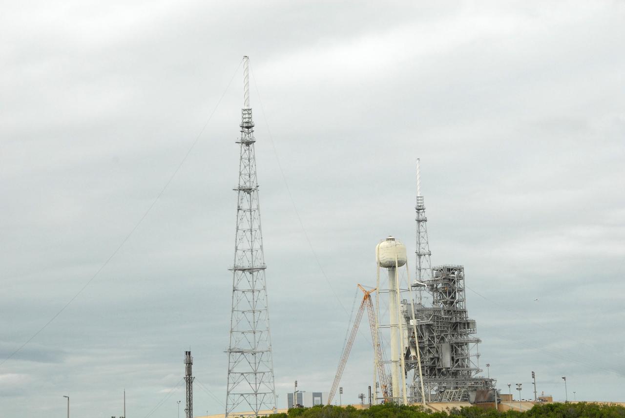
CAPE CANAVERAL, Fla. – On Launch Pad 39B at NASA's Kennedy Space Center in Florida, catenary wires are being suspended from the lighting masts on the lightning towers. The catenary wire system under development for the Constellation Program’s next-generation vehicles will significantly increase the shielding level, providing better protection, and further separate the electrical current from vital launch hardware. The system will help avoid delays to the launch schedule by collecting more information on the strike for analysis by launch managers. Photo credit: NASA/Jack Pfaller
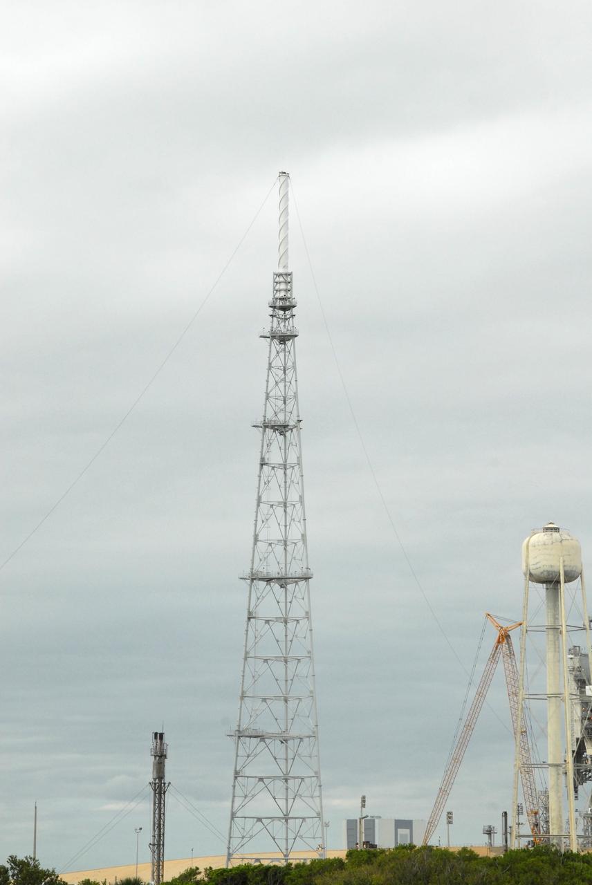
CAPE CANAVERAL, Fla. – On Launch Pad 39B at NASA's Kennedy Space Center in Florida, catenary wires are being suspended from the lighting masts on the lightning towers. The catenary wire system under development for the Constellation Program’s next-generation vehicles will significantly increase the shielding level, providing better protection, and further separate the electrical current from vital launch hardware. The system will help avoid delays to the launch schedule by collecting more information on the strike for analysis by launch managers. Photo credit: NASA/Jack Pfaller

KENNEDY SPACE CENTER, FLA. -- Danny Wyatt, with NASA Quality, inspects wiring, using a flashlight and magnifying glass, in the aft compartment of Discovery before launch. Electrical wire inspections and repairs in the orbiter's payload bay, external tank umbilical and engine compartment have been ongoing for more than a month and are near completion. Launch of Space Shuttle Discovery on mission STS-103 is scheduled for Dec. 11 at 11:42 p.m. from Launch Pad 39B. STS-103 is the third servicing mission for the Hubble Space Telescope
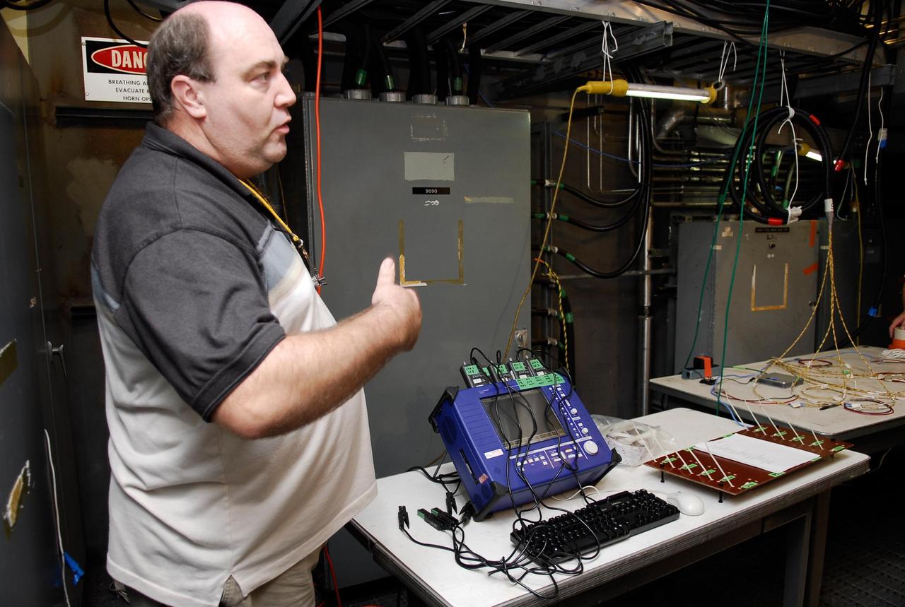
KENNEDY SPACE CENTER, FLA. -- On Launch Pad 39A, a technician explains how test equipment -- the blue monitor -- will be used to validate the circuit on test wiring from the electrical harness in space shuttle Atlantis' aft main engine compartment connected with the engine cut-off system. The test wiring leads from the tail mast on the mobile launcher platform to the interior where the Time Domain Reflectometry, or TDR, test equipment will be located to test the sensor system. Photo credit: NASA/Kim Shiflett
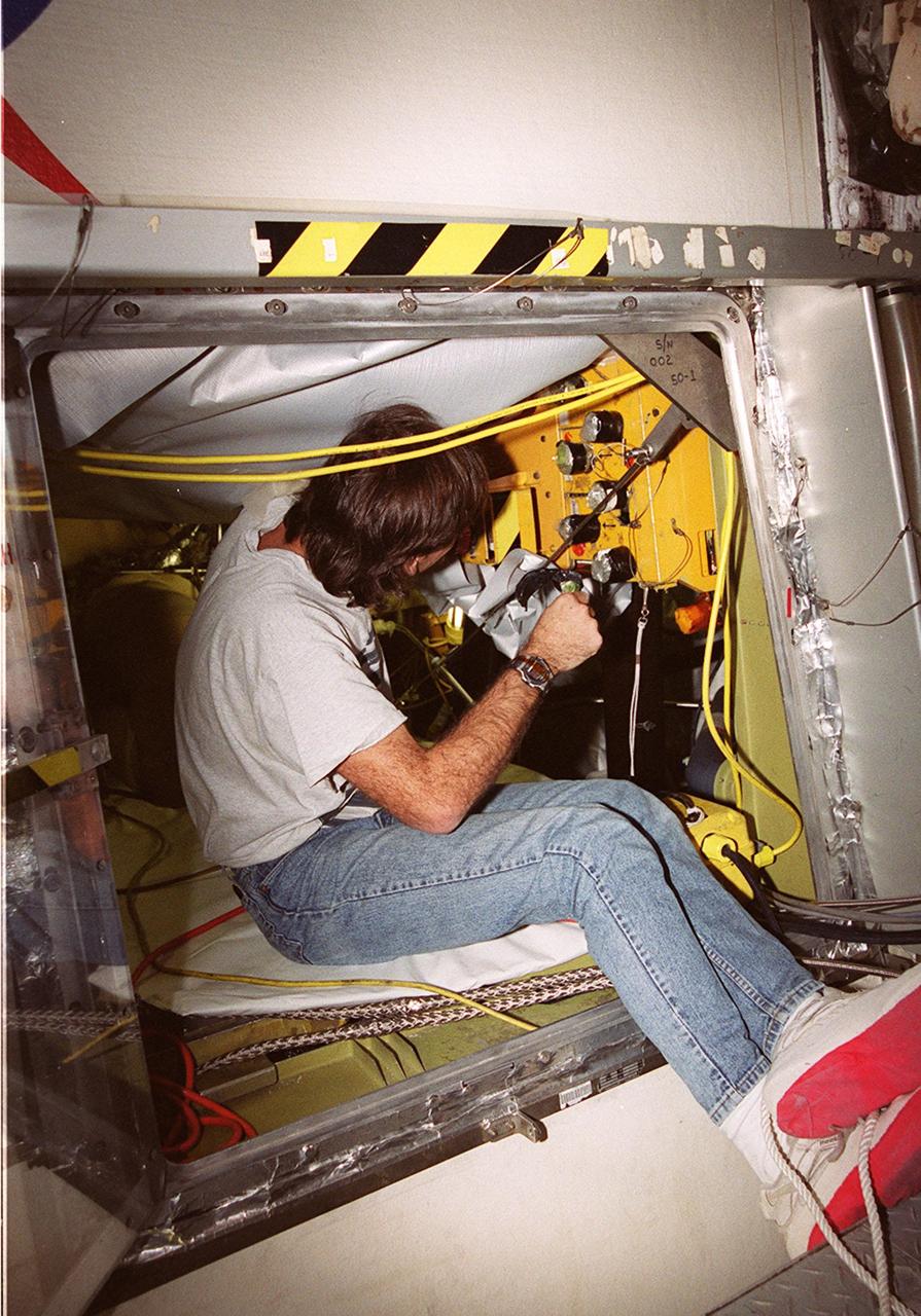
KENNEDY SPACE CENTER, FLA. -- Todd Biddle, with United Space Alliance, inspects wiring in the aft compartment of Discovery before launch. Electrical wire inspections and repairs in the orbiter's payload bay, external tank umbilical and engine compartment have been ongoing for more than a month and are near completion. Launch of Space Shuttle Discovery on mission STS-103 is scheduled for Dec. 11 at 11:42 p.m. from Launch Pad 39B. STS-103 is the third servicing mission for the Hubble Space Telescope
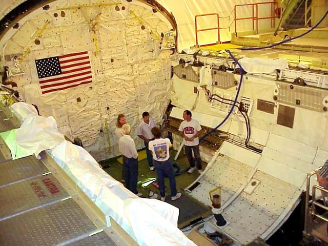
KENNEDY SPACE CENTER, FLA. -- KSC workers stand inside the payload bay of the orbiter Columbia following completion of electrical wiring inspections. At right, behind and below them is the cable tray with the wiring. During launch of Columbia on mission STS-93, a damaged wire caused a short circuit in two separate main engine controllers. As a result of the findings, Shuttle program managers decided to conduct inspections of the wiring in Endeavour's payload bay before its next mission, STS-99. The inspection and possible repair work will lead to a delayed launch date no earlier than Oct.7. The primary payload of the mission is the Shuttle Radar Topography Mission, a specially modified radar system that will gather data for the most accurate and complete topographic map of the Earth's surface that has ever been assembled
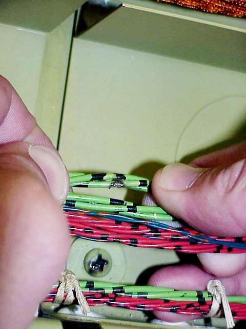
KENNEDY SPACE CENTER, FLA. -- A wire damaged by abrasion from the head of a screw (seen below the bundle) was found during electrical wiring inspections in Columbia's payload bay. During launch of Columbia on mission STS-93, a damaged wire caused a short circuit in two separate main engine controllers. As a result of the findings, Shuttle program managers have decided to conduct inspections of the wiring in Endeavour's payload bay before its next mission, STS-99. The inspection and possible repair work will lead to a delayed launch date no earlier than Oct.7. The primary payload of the mission is the Shuttle Radar Topography Mission, a specially modified radar system that will gather data for the most accurate and complete topographic map of the Earth's surface that has ever been assembled

Here is an image of the X-59’s 13-foot General Electric F414 engine as the team prepares for a fit check. Making sure components, like the aircraft’s hydraulic lines, which help control functions like brakes or landing gear, and wiring of the engine, fit properly is essential to the aircraft’s safety. Once complete, the X-59 aircraft will demonstrate the ability to fly supersonic while reducing the loud sonic boom to a quiet sonic thump and help enable commercial supersonic air travel over land.
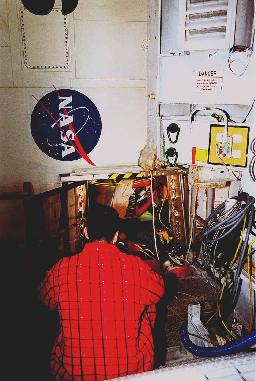
KENNEDY SPACE CENTER, FLA. -- Chris Kidd, with United Space Alliance (USA) stands by outside the aft compartment of Discovery while Todd Biddle (USA) inspects wiring inside. Electrical wire inspections and repairs in the orbiter's payload bay, external tank umbilical and engine compartment have been ongoing for more than a month and are near completion. Launch of Space Shuttle Discovery on mission STS-103 is scheduled for Dec. 11 at 11:42 p.m. from Launch Pad 39B. STS-103 is the third servicing mission for the Hubble Space Telescope
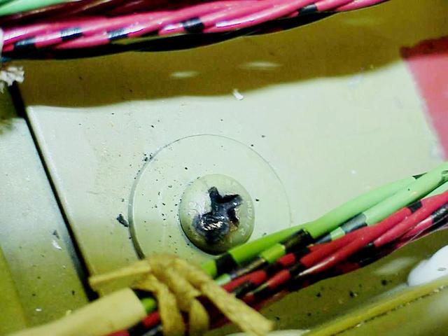
KENNEDY SPACE CENTER, FLA. -- In the orbiter Columbia's payload bay, the head of a screw (shown here) is identified as the probable cause of damage to a wire that caused a short circuit in two separate main engine controllers during launch of mission STS-93. As a result of the findings of electrical wiring inspections, Shuttle program managers have decided to inspect the wiring in Endeavour's payload bay before its next mission, STS-99. The inspection and possible repair work will lead to a delayed launch date no earlier than Oct.7. The primary payload of the mission is the Shuttle Radar Topography Mission, a specially modified radar system that will gather data for the most accurate and complete topographic map of the Earth's surface that has ever been assembled

KENNEDY SPACE CENTER, FLA. -- At Launch Pad 39A, a United Space Alliance technician carefully cuts away the foam insulation surrounding the covers over the feed-through connector box on the external tank for space shuttle Atlantis' STS-122 mission. The covers will be removed for access to the feed-through connectors. Following the failure of some of the tank's engine cutoff sensors, or ECO sensors, during propellant tanking for launch attempts on Dec. 6 and Dec. 9, a tanking test was conducted on Dec. 18 to aid in troubleshooting the cause. Technicians spliced test wiring into the ECO sensor electrical system and used time domain reflectometry equipment to help locate the electrical anomaly. Results of the tanking test pointed to an open circuit in the feed-through connector wiring, which is located at the base of the tank. The feed-through connector passes the wires from the inside of the tank to the outside. During the holiday period, workers from Lockheed Martin will begin inspecting and testing the connector. Shuttle program managers will meet on Dec. 27 to review the test and analysis, and decide on a forward plan. Photo credit: NASA/Kim Shiflett
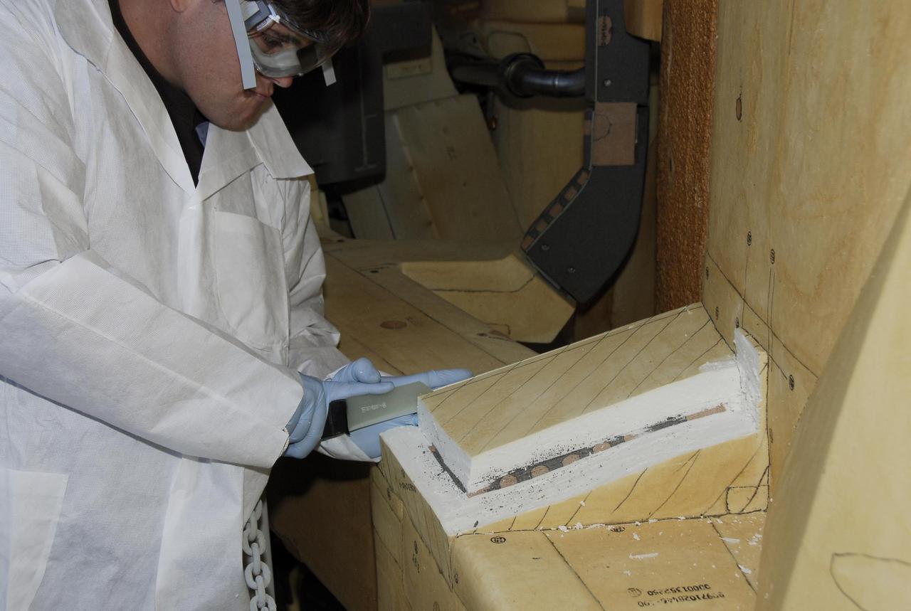
KENNEDY SPACE CENTER, FLA. -- At Launch Pad 39A, a United Space Alliance technician carefully cuts away the foam insulation surrounding the covers over the feed-through connector box on the external tank for space shuttle Atlantis' STS-122 mission, revealing the fastener holes on the covers. The covers will be removed for access to the feed-through connectors. Following the failure of some of the tank's engine cutoff sensors, or ECO sensors, during propellant tanking for launch attempts on Dec. 6 and Dec. 9, a tanking test was conducted on Dec. 18 to aid in troubleshooting the cause. Technicians spliced test wiring into the ECO sensor electrical system and used time domain reflectometry equipment to help locate the electrical anomaly. Results of the tanking test pointed to an open circuit in the feed-through connector wiring, which is located at the base of the tank. The feed-through connector passes the wires from the inside of the tank to the outside. During the holiday period, workers from Lockheed Martin will begin inspecting and testing the connector. Shuttle program managers will meet on Dec. 27 to review the test and analysis, and decide on a forward plan. Photo credit: NASA/Kim Shiflett
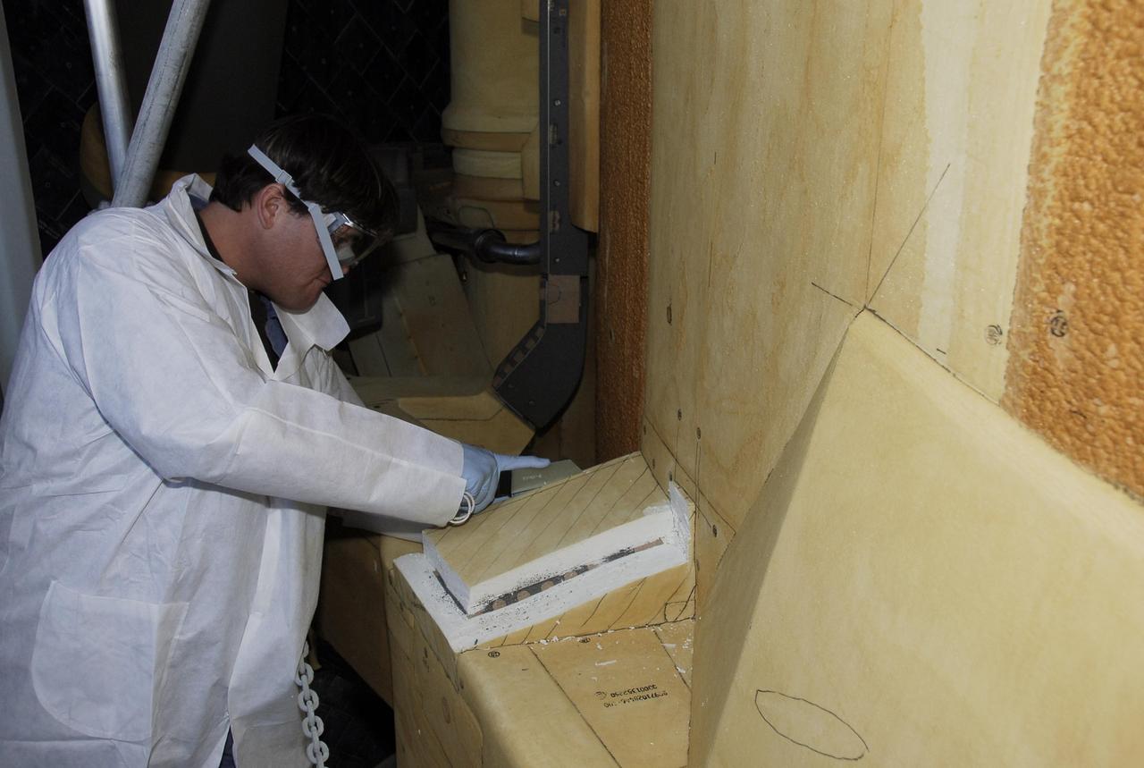
KENNEDY SPACE CENTER, FLA. -- At Launch Pad 39A, a United Space Alliance technician carefully cuts away the foam insulation surrounding the covers over the feed-through connector box on the external tank for space shuttle Atlantis' STS-122 mission, revealing the fastener holes on the covers. The covers will be removed for access to the feed-through connectors. Following the failure of some of the tank's engine cutoff sensors, or ECO sensors, during propellant tanking for launch attempts on Dec. 6 and Dec. 9, a tanking test was conducted on Dec. 18 to aid in troubleshooting the cause. Technicians spliced test wiring into the ECO sensor electrical system and used time domain reflectometry equipment to help locate the electrical anomaly. Results of the tanking test pointed to an open circuit in the feed-through connector wiring, which is located at the base of the tank. The feed-through connector passes the wires from the inside of the tank to the outside. During the holiday period, workers from Lockheed Martin will begin inspecting and testing the connector. Shuttle program managers will meet on Dec. 27 to review the test and analysis, and decide on a forward plan. Photo credit: NASA/Kim Shiflett

KENNEDY SPACE CENTER, FLA. -- At Launch Pad 39A, a United Space Alliance technician removes foam insulation revealing the fastener holes on the covers over the feed-through connector box on the external tank for space shuttle Atlantis' STS-122 mission. The covers will be removed for access to the feed-through connectors. Following the failure of some of the tank's engine cutoff sensors, or ECO sensors, during propellant tanking for launch attempts on Dec. 6 and Dec. 9, a tanking test was conducted on Dec. 18 to aid in troubleshooting the cause. Technicians spliced test wiring into the ECO sensor electrical system and used time domain reflectometry equipment to help locate the electrical anomaly. Results of the tanking test pointed to an open circuit in the feed-through connector wiring, which is located at the base of the tank. The feed-through connector passes the wires from the inside of the tank to the outside. During the holiday period, workers from Lockheed Martin will begin inspecting and testing the connector. Shuttle program managers will meet on Dec. 27 to review the test and analysis, and decide on a forward plan. Photo credit: NASA/Kim Shiflett
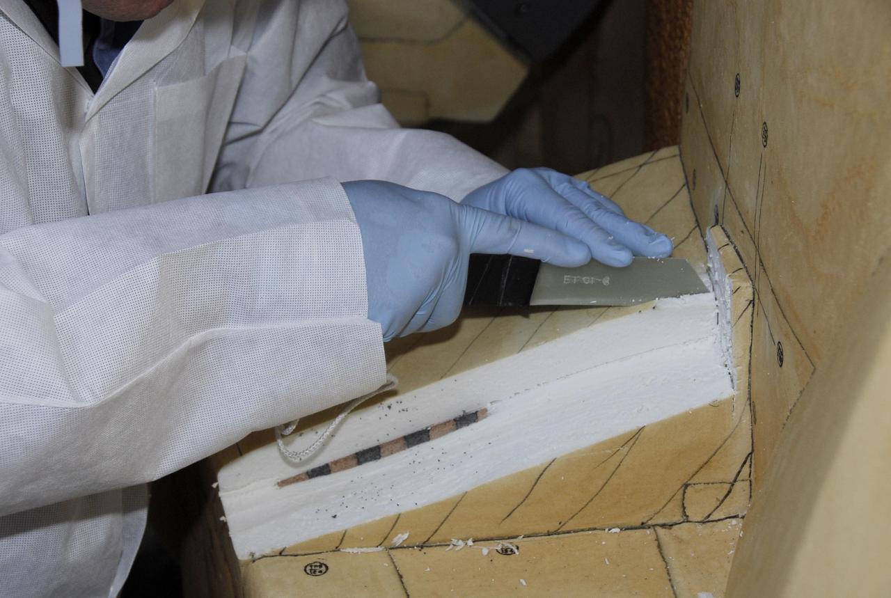
KENNEDY SPACE CENTER, FLA. -- At Launch Pad 39A, the foam insulation surrounding the covers over the feed-through connector box on the external tank for space shuttle Atlantis' STS-122 mission is carefully cut away by a United Space Alliance technician. The covers will be removed for access to the feed-through connectors. Following the failure of some of the tank's engine cutoff sensors, or ECO sensors, during propellant tanking for launch attempts on Dec. 6 and Dec. 9, a tanking test was conducted on Dec. 18 to aid in troubleshooting the cause. Technicians spliced test wiring into the ECO sensor electrical system and used time domain reflectometry equipment to help locate the electrical anomaly. Results of the tanking test pointed to an open circuit in the feed-through connector wiring, which is located at the base of the tank. The feed-through connector passes the wires from the inside of the tank to the outside. During the holiday period, workers from Lockheed Martin will begin inspecting and testing the connector. Shuttle program managers will meet on Dec. 27 to review the test and analysis, and decide on a forward plan. Photo credit: NASA/Kim Shiflett
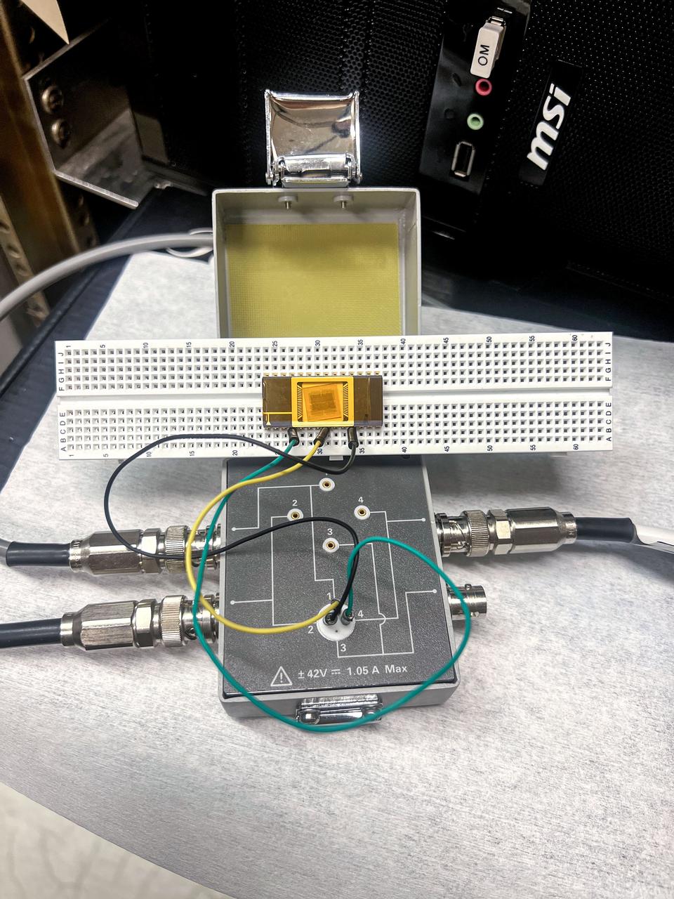
jsc2025e015683 (3/6/2025) --- The chip carrier setup shows the GaN devices are wire bonded to perform electrical measurement as part of the High Performance Radiation Hardened GaN High Electron Mobility Transistors for Space Applications (Radiation Harden GaN) investigation which studies how radiation affects a type of transistor used in the semiconductor industry. Researchers measure the performance of the devices before, during, and after flight to determine whether performance degrades. This could help determine how well the transistors can tolerate radiation in space. Image courtesy of Department of Electrical and Computer Engineering, University of Delaware.
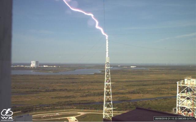
A lightning strike is recorded at Launch Complex 39B at NASA’s Kennedy Space Center in Florida in August 2019. The event was captured by high-speed cameras stationed at the pad and mobile launcher using a special filter called a “clear day frame,” which provides an overlay of the raw frame on a reference image. At pad 39B, there are three, 600-foot-tall masts with overhead wires used to transmit electrical energy around the perimeter of the pad to provide lightning protection for launch vehicles as they are processed and launched from the pad.
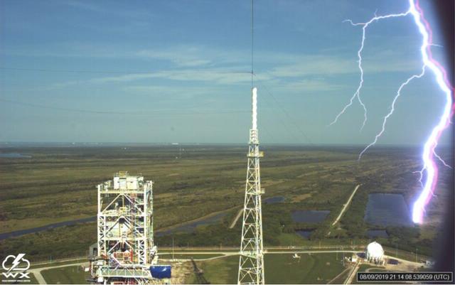
A lightning strike is recorded at Launch Complex 39B at NASA’s Kennedy Space Center in Florida in August 2019. The event was captured by high-speed cameras stationed at the pad and mobile launcher using a special filter called a “clear day frame,” which provides an overlay of the raw frame on a reference image. At pad 39B, there are three, 600-foot-tall masts with overhead wires used to transmit electrical energy around the perimeter of the pad to provide lightning protection for launch vehicles as they are processed and launched from the pad.
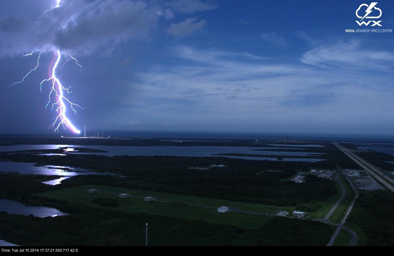
A lightning strike is recorded at Launch Complex 39B at NASA’s Kennedy Space Center in Florida in July 2014. The event was captured by high-speed camera from the iconic Vehicle Assembly Building. At pad 39B, there are three, 600-foot-tall masts with overhead wires used to transmit electrical energy around the perimeter of the pad to provide lightning protection for launch vehicles as they are processed and launched from the pad.
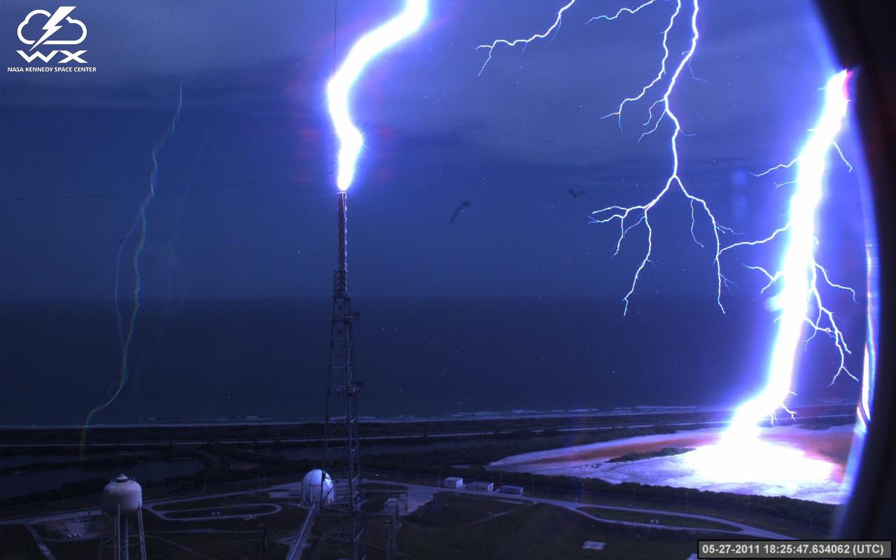
A lightning strike is recorded at Launch Complex 39B at NASA’s Kennedy Space Center in Florida in May 2011. The event was captured by high-speed cameras stationed at the pad and mobile launcher. At pad 39B, there are three, 600-foot-tall masts with overhead wires used to transmit electrical energy around the perimeter of the pad to provide lightning protection for launch vehicles as they are processed and launched from the pad.

The Orion crew module adapter for NASA’s Artemis III campaign undergoes wiring installs inside the Neil A. Armstrong Operations and Checkout Building at NASA’s Kennedy Space Center on Wednesday, Sept. 4, 2024. In Orion’s final configuration before launch, the crew module adapter connects the capsule to the European Service Module 3. The crew module adapter houses electronic equipment for communications, power, and control, and includes an umbilical connector that bridges the electrical, data, and fluid systems between the main modules.
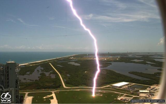
A lightning strike is recorded at Launch Complex 39B at NASA’s Kennedy Space Center in Florida in August 2019. The event was captured by high-speed cameras stationed at the pad and mobile launcher using a special filter called a “clear day frame,” which provides an overlay of the raw frame on a reference image. At pad 39B, there are three, 600-foot-tall masts with overhead wires used to transmit electrical energy around the perimeter of the pad to provide lightning protection for launch vehicles as they are processed and launched from the pad.
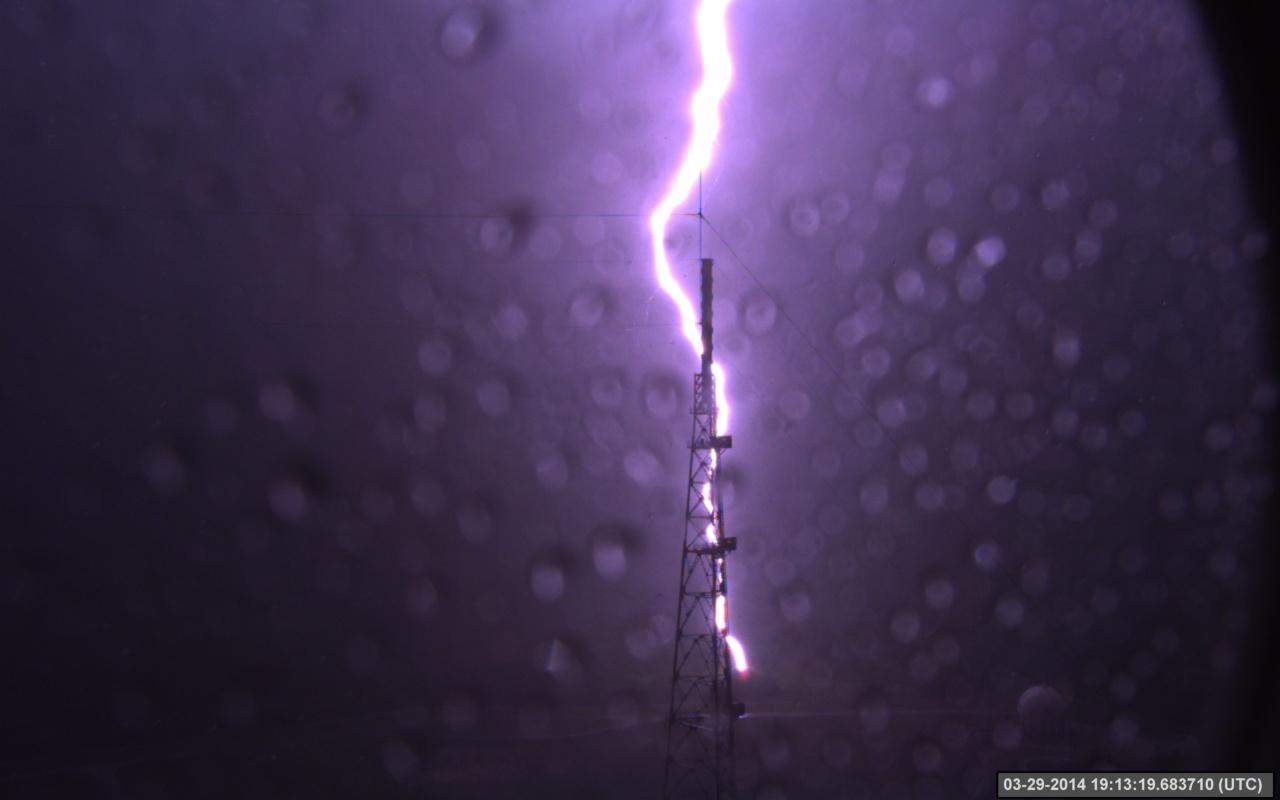
A lightning strike is recorded at Launch Complex 39B at NASA’s Kennedy Space Center in Florida in March 2014. The event was captured by high-speed cameras stationed at the pad and mobile launcher. At pad 39B, there are three, 600-foot-tall masts with overhead wires used to transmit electrical energy around the perimeter of the pad to provide lightning protection for launch vehicles as they are processed and launched from the pad.
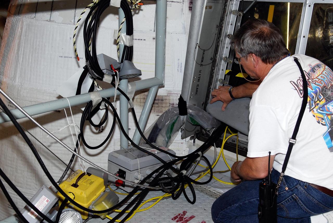
KENNEDY SPACE CENTER, FLA. -- On Launch Pad 39A, a technician checks test wiring spliced into an electrical harness in space shuttle Atlantis' aft main engine compartment connected with the engine cut-off, or ECO, system. The test wiring leads to the interior of the mobile launcher platform where the Time Domain Reflectometry, or TDR, test equipment will be located to test the sensor system. The shuttle's planned launches on Dec. 6 and Dec. 9 were postponed because of false readings from the part of the ECO system that monitors the liquid hydrogen section of the tank. The liftoff date from NASA's Kennedy Space Center, Florida, is now targeted for Jan. 10, depending on the resolution of the problem in the fuel sensor system. Photo credit: NASA/Kim Shiflett
KENNEDY SPACE CENTER, FLA. -- On Launch Pad 39A, a technician checks test wiring spliced into an electrical harness in space shuttle Atlantis' aft main engine compartment connected with the engine cut-off, or ECO, system. The test wiring leads to the interior of the mobile launcher platform where the Time Domain Reflectometry, or TDR, test equipment will be located to test the sensor system. The shuttle's planned launches on Dec. 6 and Dec. 9 were postponed because of false readings from the part of the ECO system that monitors the liquid hydrogen section of the tank. The liftoff date from NASA's Kennedy Space Center, Florida, is now targeted for Jan. 10, depending on the resolution of the problem in the fuel sensor system. Photo credit: NASA/Kim Shiflett
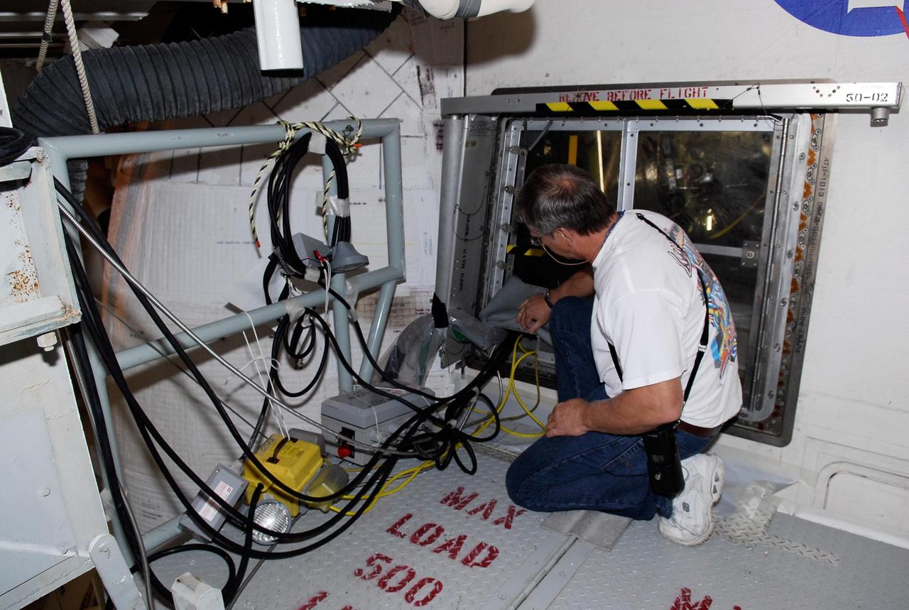
KENNEDY SPACE CENTER, FLA. -- On Launch Pad 39A, a technician checks test wiring spliced into an electrical harness in space shuttle Atlantis' aft main engine compartment connected with the engine cut-off, or ECO, system. The test wiring leads to the interior of the mobile launcher platform where the Time Domain Reflectometry, or TDR, test equipment will be located to test the sensor system. The shuttle's planned launches on Dec. 6 and Dec. 9 were postponed because of false readings from the part of the ECO system that monitors the liquid hydrogen section of the tank. The liftoff date from NASA's Kennedy Space Center, Florida, is now targeted for Jan. 10, depending on the resolution of the problem in the fuel sensor system. Photo credit: NASA/Kim Shiflett
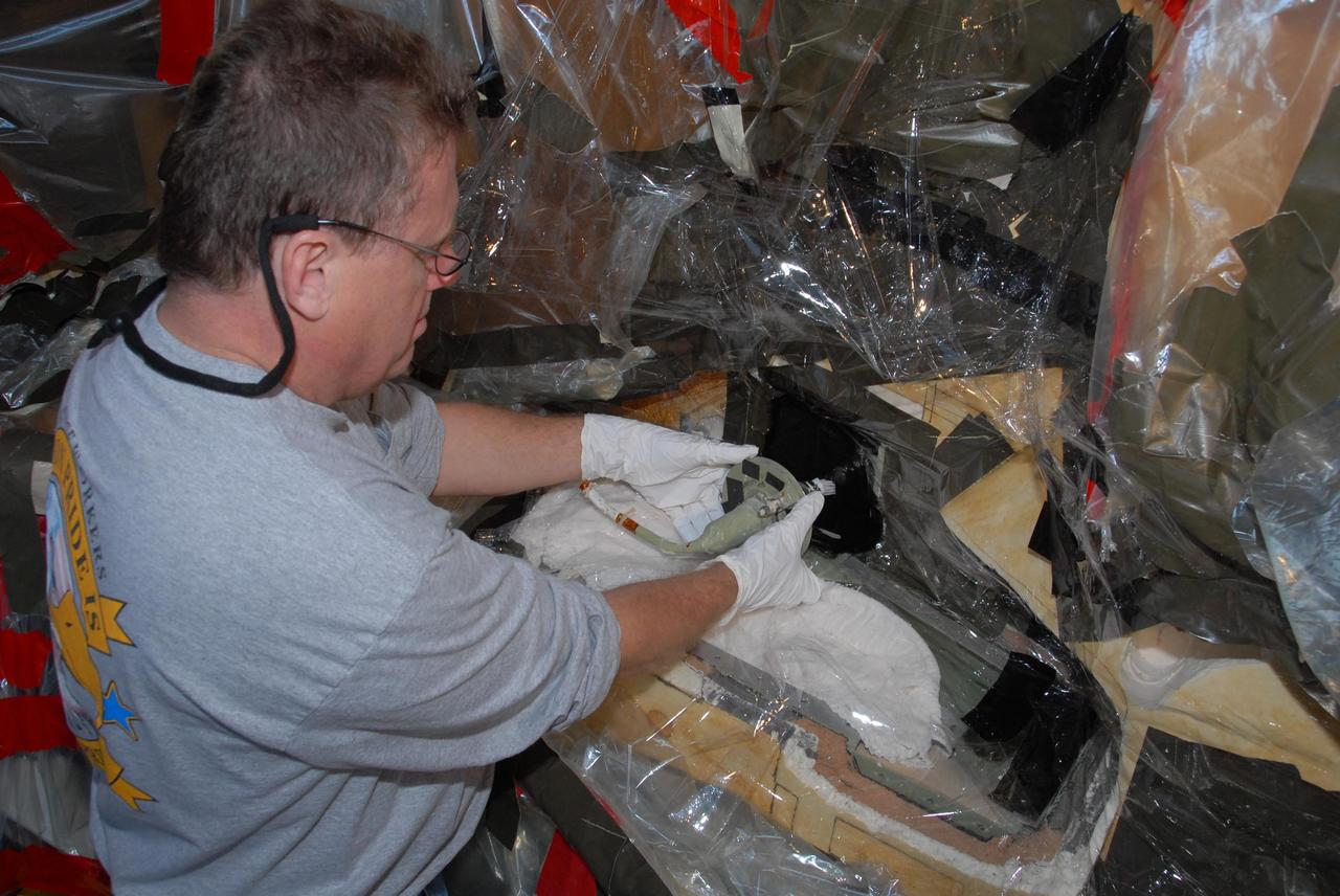
KENNEDY SPACE CENTER, FLA. -- At Launch Pad 39A, a team of external tank specialists from Lockheed Martin and the United Space Alliance undertakes the task of removing the hydrogen feed-through connector in support of space shuttle Atlantis' STS-122 mission. Here, a technician pulls the connector assembly, with its associated electrical harness, away from the tank. Some of the tank's engine cutoff sensors, or ECO sensors, failed during propellant tanking for launch attempts on Dec. 6 and Dec. 9. Results of a tanking test on Dec. 18 pointed to an open circuit in the feed-through connector wiring, which is located at the base of the tank. The feed-through connector passes the wires from the inside of the tank to the outside. After the data from additional testing on the connector is analyzed, shuttle program managers will decide on a forward plan. Launch of STS-122 is targeted for January 2008. Photo credit: NASA/George Shelton
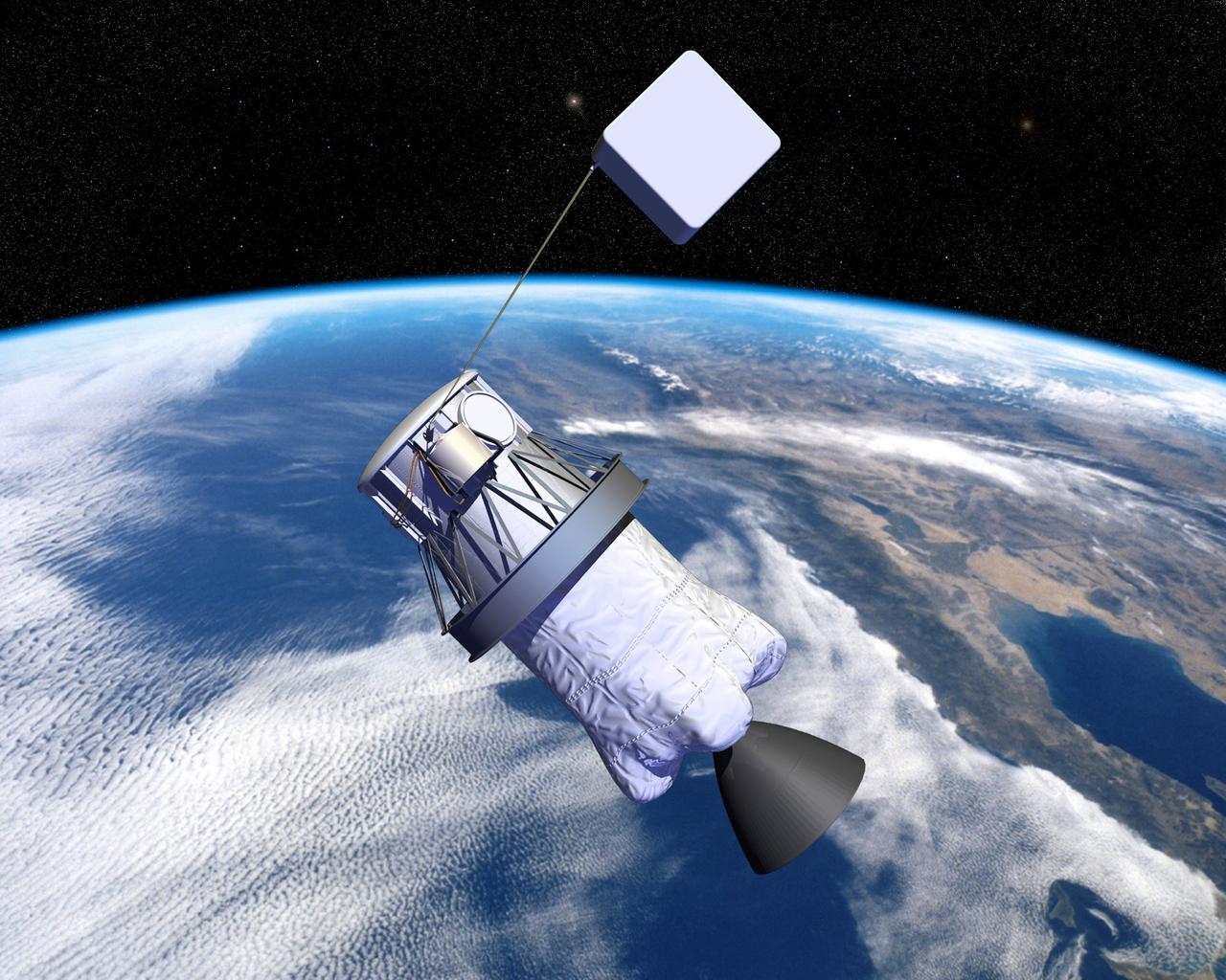
Pictured is an artist's concept of NASA's Propulsive Small Expendable Deployer System experiment (ProSEDS). ProSEDS will demonstrate the use of an electrodynamic tether, basically a long, thin wire, for propulsion. An electrodynamic tether uses the same principles as electric motors in toys, appliances and computer disk drives, and generators in automobiles and power plants. When electrical current is flowing through the tether, a magnetic field is produced that pushes against the magnetic field of the Earth. For ProSEDS, the current in the tether results by virtue of the voltage generated when the tether moves through the Earth's magnetic field at more than 17,000 mph. This approach can produce drag thrust generating useable power. Since electrodynamic tethers require no propellant, they could substantially reduce the weight of the spacecraft and provide a cost-effective method of reboosting spacecraft. The initial flight of ProSEDS is scheduled to fly aboard an Air Force Delta II rocket in summer of 2002. In orbit, ProSEDS will deploy from a Delta II second stage. It will be a 3.1-mile (5 kilometer) long, ultrathin base-wire tether cornected with a 6.2-mile (10 kilometer) long nonconducting tether. The ProSEDS experiment is managed by the Space Transportation Directorate at the Marshall Space Flight Center.
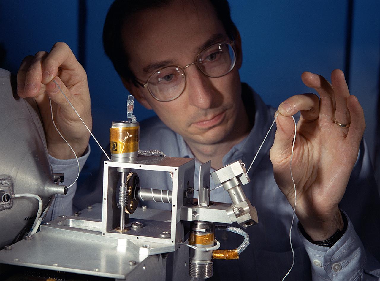
NASA's Propulsive Small Expendable Deployer System experiment (ProSEDS) will demonstrate the use of an electrodynamic tether, basically a long, thin wire, for propulsion. An electrodynamic tether uses the same principles as electric motors in toys, appliances and computer disk drives, and generators in automobiles and power plants. When electrical current is flowing through the tether, a magnetic field is produced that pushes against the magnetic field of the Earth. For ProSEDS, the current in the tether results by virtue of the voltage generated when the tether moves through the Earth's magnetic field at more than 17,000 mph. This approach can produce drag thrust generating useable power. Since electrodynamic tethers require no propellant, they could substantially reduce the weight of the spacecraft and provide a cost-effective method of reboosting spacecraft. The initial flight of ProSEDS is scheduled to fly aboard an Air Force Delta II rocket in the summer of 2002. In orbit, ProSEDS will deploy from a Delta II second stage. It will be a 3.1-mile (5 kilometer) long, ultrathin base-wire cornected with a 6.2-mile (10 kilometer) long nonconducting tether. This photograph shows Less Johnson, a scientist at MSFC inspecting the nonconducting part of a tether as it exits a deployer similar to the one to be used in the ProSEDS experiment. The ProSEDS experiment is managed by the Space Transportation Directorate at MSFC.
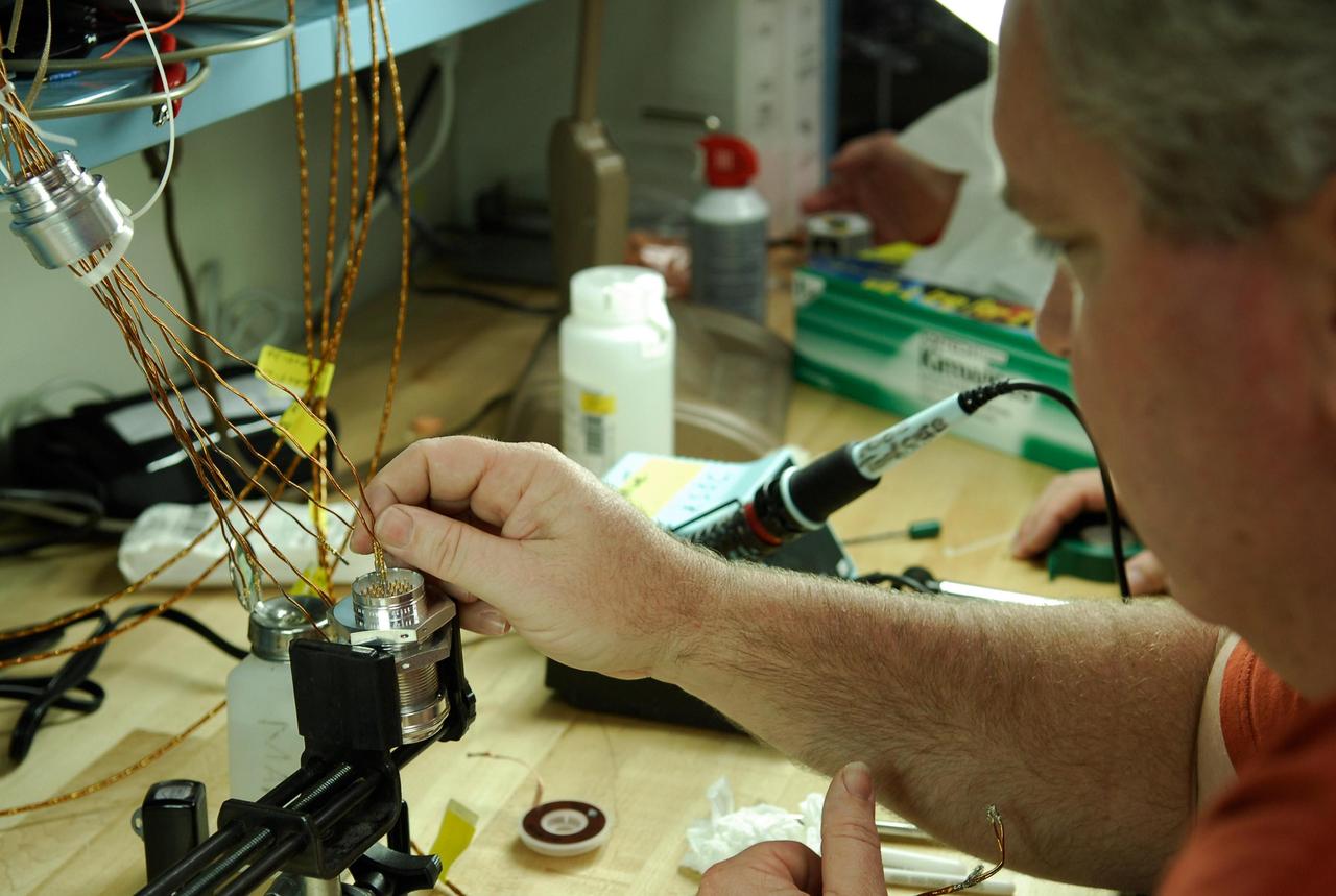
KENNEDY SPACE CENTER, FLA. -- At a lab at NASA's Kennedy Space Center, Bob Arp, an aerospace technician with the United Launch Alliance, inserts a wire from an electrical harness onto the pin of a replacement feed-through connector during preparations to solder the pins to the socket of the connector. The connector will be installed in the external fuel tank for space shuttle Atlantis' STS-122 mission. The technician performed this exacting task on the Centaur upper stage for Atlas and Titan launches in 1994 and was specifically chosen for the task. Soldering the connector pins and sockets together addresses the most likely cause of a problem in the engine cutoff sensor system, or ECO system. Some of the tank's ECO sensors failed during propellant tanking for launch attempts on Dec. 6 and Dec. 9. Results of a tanking test on Dec. 18 pointed to an open circuit in the feed-through connector wiring, which is located at the base of the tank. The feed-through connector passes the wires from the inside of the tank to the outside. After the soldering is completed and the connector is reinstalled, shuttle program managers will decide on how to proceed. The launch date for mission STS-122 is under review. Photo credit: NASA/Kim Shiflett
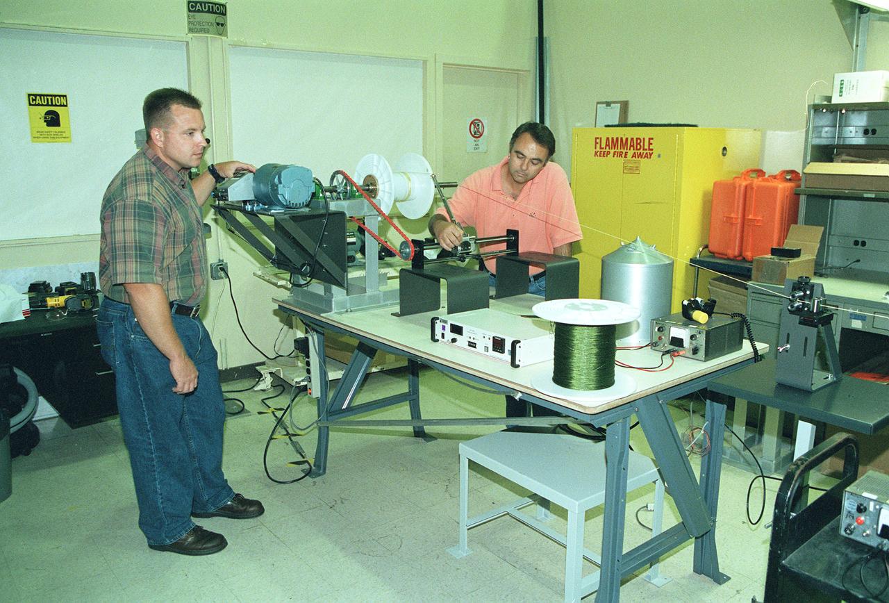
This photograph shows two Marshall Space Flight Center (MSFC) engineers, Mark Vaccaro (left) and Ken Welzyn, testing electrodynamic tethers in the MSFC Tether Winding and Spark Testing Facility. For 4 years, MSFC and industry partners have been developing the Propulsive Small Expendable Deployer System experiment, called ProSEDS. ProSEDS will test electrodynamic tether propulsion technology. Electrodynamic tethers are long, thin wires that collect electrical current when passing through a magnetic field. The tether works as a thruster as a magnetic field exerts a force on a current-carrying wire. Since electrodynamic tethers require no propellant, they could substantially reduce the weight of the spacecraft and provide a cost-effective method of reboosting spacecraft. The initial flight of ProSEDS is scheduled to fly aboard an Air Force Delta II rocket in the summer of 2002. In orbit, ProSEDS will deploy from a Delta II second stage. It will be a 3.1-mile (5 kilometer) long, ultrathin base-wire tether cornected with a 6.2-mile (10 kilometer) long non-conducting tether. This photograph shows Less Johnson, a scientist at MSFC, inspecting the nonconducting part of a tether as it exits a deployer similar to the one to be used in the ProSEDS experiment. The ProSEDS experiment is managed by the Space Transportation Directorate at MSFC.
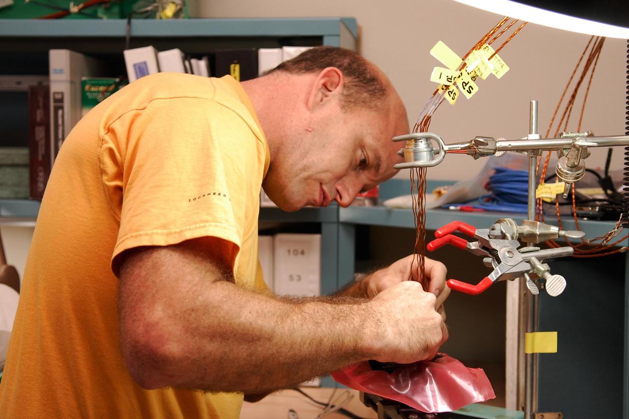
KENNEDY SPACE CENTER, FLA. -- At a lab at NASA's Kennedy Space Center, Kevin Wyckoff, an aerospace technician with the United Launch Alliance, inserts an electrical wiring harness into a replacement feed-through connector during preparations to solder the pins to the socket of the connector. The connector will later be installed in the external fuel tank for space shuttle Atlantis' STS-122 mission. The technician performed this exacting task on the Centaur upper stage for Atlas and Titan launches in 1994 and was specifically chosen for the task. Soldering the connector pins and sockets together addresses the most likely cause of a problem in the engine cutoff sensor system, or ECO system. Some of the tank's ECO sensors failed during propellant tanking for launch attempts on Dec. 6 and Dec. 9. Results of a tanking test on Dec. 18 pointed to an open circuit in the feed-through connector wiring, which is located at the base of the tank. The feed-through connector passes the wires from the inside of the tank to the outside. After the soldering is completed and the connector is reinstalled, shuttle program managers will decide on how to proceed. The launch date for mission STS-122 is under review. Photo credit: NASA/Kim Shiflett
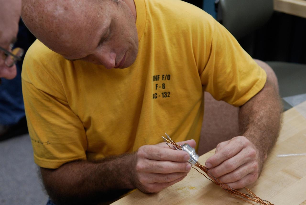
KENNEDY SPACE CENTER, FLA. -- At a lab at NASA's Kennedy Space Center, Kevin Wyckoff, an aerospace technician with the United Launch Alliance, examines an electrical wiring harness. The harness will be inserted into a replacement feed-through connector during preparations to solder the pins to the socket of the connector. The connector will later be installed in the external fuel tank for space shuttle Atlantis' STS-122 mission. The technician performed this exacting task on the Centaur upper stage for Atlas and Titan launches in 1994 and was specifically chosen for the task. Soldering the connector pins and sockets together addresses the most likely cause of a problem in the engine cutoff sensor system, or ECO system. Some of the tank's ECO sensors failed during propellant tanking for launch attempts on Dec. 6 and Dec. 9. Results of a tanking test on Dec. 18 pointed to an open circuit in the feed-through connector wiring, which is located at the base of the tank. The feed-through connector passes the wires from the inside of the tank to the outside. After the soldering is completed and the connector is reinstalled, shuttle program managers will decide on how to proceed. The launch date for mission STS-122 is under review. Photo credit: NASA/Kim Shiflett

KENNEDY SPACE CENTER, FLA. -- At a lab at NASA's Kennedy Space Center, aerospace technicians with the United Launch Alliance inspect an electrical wiring harness that has been inserted into a replacement feed-through connector during preparations to solder the pins to the socket of the connector that will be installed in the external fuel tank for space shuttle Atlantis' STS-122 mission. The technicians performed this exacting task on the Centaur upper stage for Atlas and Titan launches in 1994 and were specifically chosen for the task. Soldering the connector pins and sockets together addresses the most likely cause of a problem in the engine cutoff sensor system, or ECO system. Some of the tank's ECO sensors failed during propellant tanking for launch attempts on Dec. 6 and Dec. 9. Results of a tanking test on Dec. 18 pointed to an open circuit in the feed-through connector wiring, which is located at the base of the tank. The feed-through connector passes the wires from the inside of the tank to the outside. After the soldering is completed and the connector is reinstalled, shuttle program managers will decide on how to proceed. The launch date for mission STS-122 is under review. Photo credit: NASA/Kim Shiflett
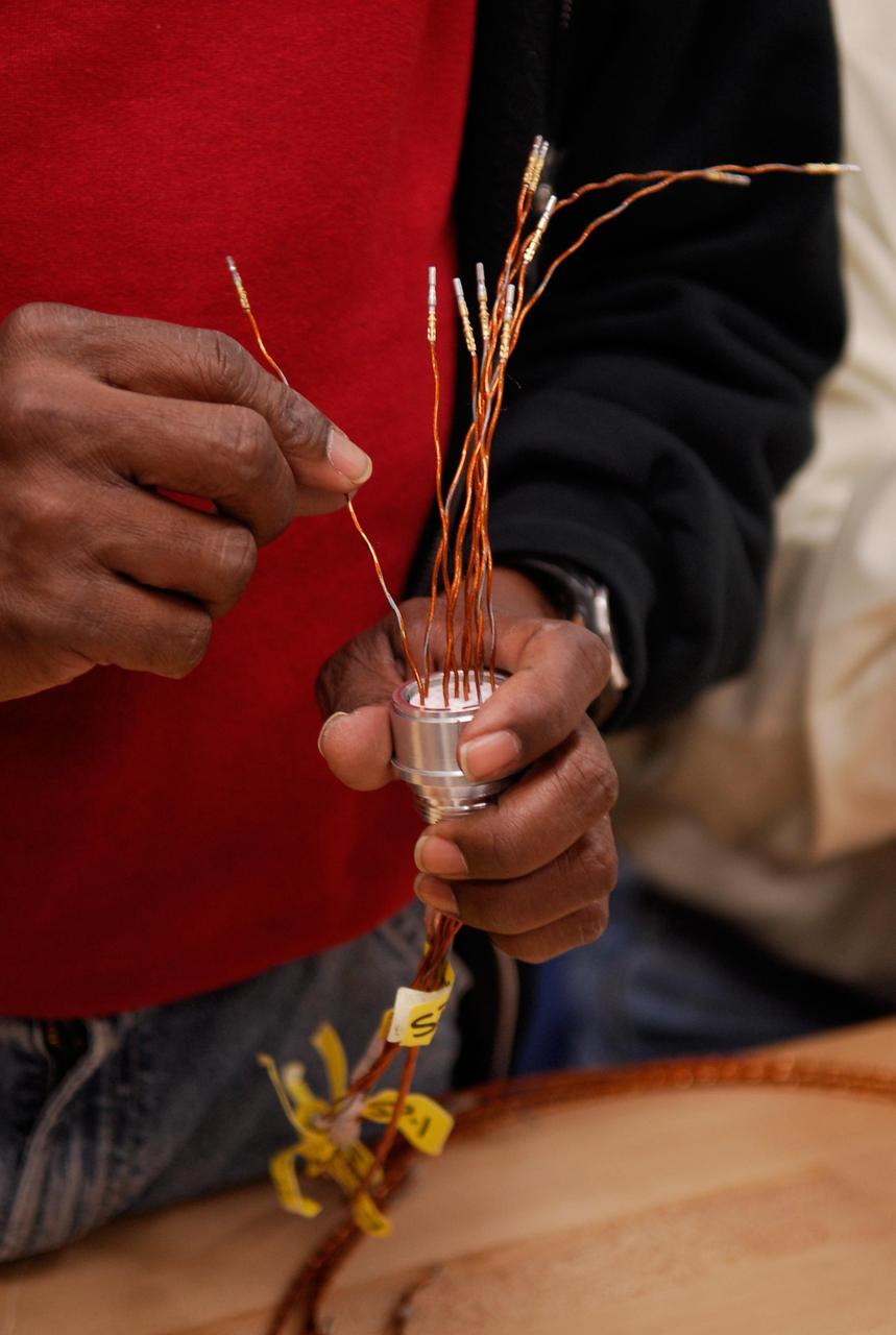
KENNEDY SPACE CENTER, FLA. -- At a lab at NASA's Kennedy Space Center, a Lockheed Martin technician prepares an electrical wiring harness during a procedure to solder the pins to the socket of the replacement feed-through connector that will be installed in the external fuel tank for space shuttle Atlantis' STS-122 mission. Two United Launch Alliance technicians, who performed this exacting task on the Centaur upper stage for Atlas and Titan launches in 1994, will be doing the soldering. Soldering the connector pins and sockets together addresses the most likely cause of a problem in the engine cutoff sensor system, or ECO system. Some of the tank's ECO sensors failed during propellant tanking for launch attempts on Dec. 6 and Dec. 9. Results of a tanking test on Dec. 18 pointed to an open circuit in the feed-through connector wiring, which is located at the base of the tank. The feed-through connector passes the wires from the inside of the tank to the outside. After the soldering is completed and the connector is reinstalled, shuttle program managers will decide on how to proceed. The launch date for mission STS-122 is under review. Photo credit: NASA/Kim Shiflett
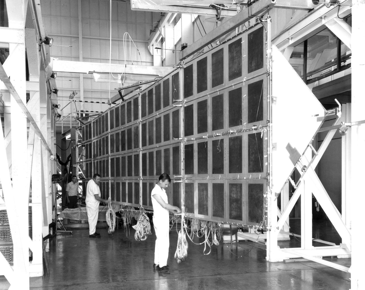
Technicians at NASA’s Marshall Space Flight Center check the wiring on a mechanical test article of the Apollo Telescope Mount (ATM) solar array. Four such arrays were joined in a cross to provide electric power for the ATM in Earth orbit. The deployment mechanism for extending the wing to the fully open position had just been tested when this photograph was taken. The array was suspended from beams riding on air bearings to closely simulate the weightless conditions under which it would be deployed in space. The wings are folded against the sides of the ATM for launch and are deployed by a scissors mechanism in Earth’s orbit.
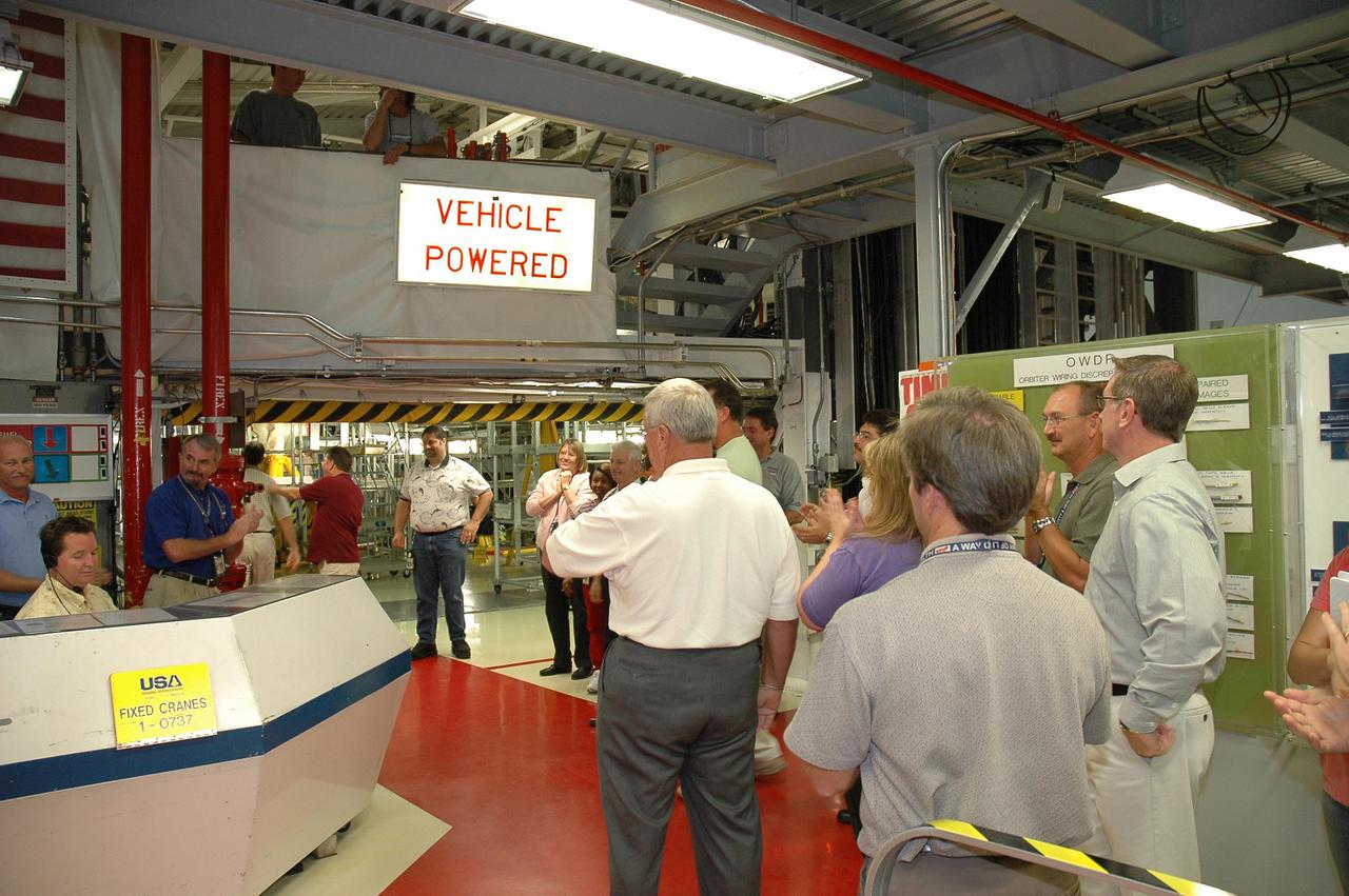
KENNEDY SPACE CENTER, FLA. - In NASA’s Orbiter Processing Facility bay 2, workers gather as the orbiter Endeavour’s electrical system is partially powered up, after nearly 2 years. Full power-up will take place in October. Endeavour has been in its Orbiter Major Modification period, which began in December 2003. In that time, 124 modifications were completed, including installing the glass cockpit; 150 miles of wiring were inspected; and more than 1,000 tiles were bonded. This is the second full modification conducted at Kennedy.
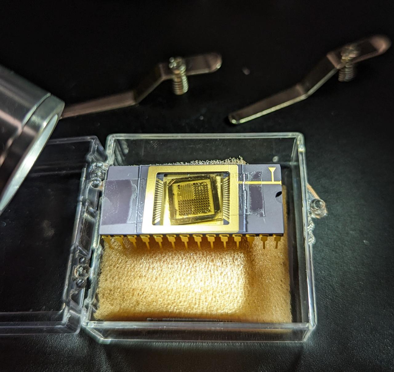
jsc2025e015685c(3/6/2025) --- The GaN devices wire bonded to a chip carrier as part of the High Performance Radiation Hardened GaN High Electron Mobility Transistors for Space Applications (Radiation Harden GaN) investigation which studies how radiation affects a type of transistor used in the semiconductor industry. Researchers measure the performance of the devices before, during, and after flight to determine whether performance degrades. This could help determine how well the transistors can tolerate radiation in space. Image courtesy of Department of Electrical and Computer Engineering, University of Delaware.
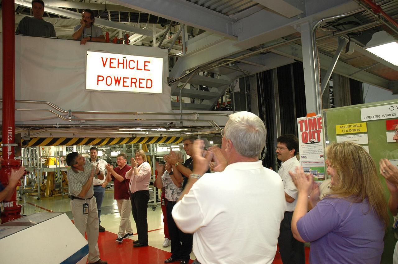
KENNEDY SPACE CENTER, FLA. - In NASA’s Orbiter Processing Facility bay 2, workers applaud as the orbiter Endeavour’s electrical system is partially powered up, after nearly 2 years. Full power-up will take place in October. Endeavour has been in its Orbiter Major Modification period, which began in December 2003. In that time, 124 modifications were completed, including installing the glass cockpit; 150 miles of wiring were inspected; and more than 1,000 tiles were bonded. This is the second full modification conducted at Kennedy.
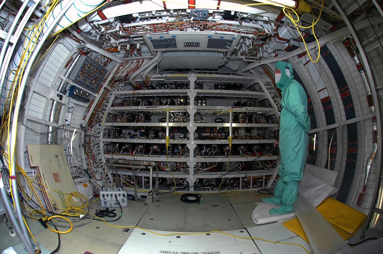
KENNEDY SPACE CENTER, FLA. - In Orbiter Processing Facility bay 2, United Space Alliance technician Rob Lewis monitors Space Shuttle Endeavour's electrical system the first time the orbiter is powered up after nearly two years. Endeavour has been in its Orbiter Major Modification (OMM) period since December 2003. Engineers and technicians spent 900,000 hours performing 124 modifications to the vehicle. These included all recommended return to flight safety modifications, bonding more than 1,000 thermal protection system tiles and inspecting more than 150 miles of wiring throughout Endeavour. Eighty five of the modifications are completed, with work on the additional 39 modifications continuing throughout the next few months. Shuttle major modification periods are scheduled at regular intervals to enhance safety and performance, infuse new technology and allow for thorough inspections of the airframe and wiring of the vehicles. This was the second of these modification periods performed entirely at Kennedy Space Center. Endeavour's previous modification was completed in March 1997.
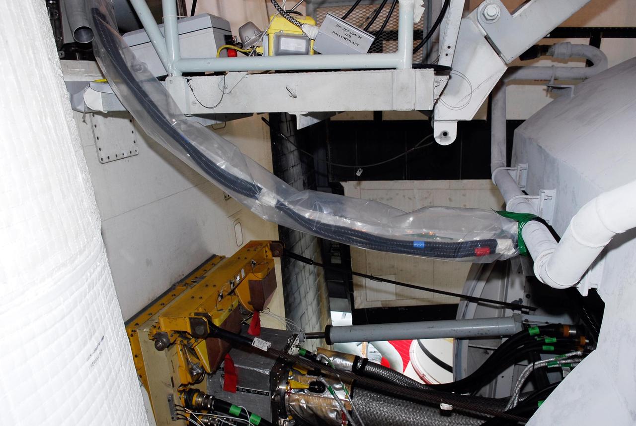
KENNEDY SPACE CENTER, FLA. -- On Launch Pad 39A, cables lead from an electrical harness in space shuttle Atlantis' aft main engine compartment connected with the engine cut-off, or ECO, system into the tail mast. The test wiring leads from the tail mast to the interior of the mobile launcher platform where the Time Domain Reflectometry, or TDR, test equipment will be located to test the sensor system. The shuttle's planned launches on Dec. 6 and Dec. 9 were postponed because of false readings from the part of the ECO system that monitors the liquid hydrogen section of the tank. The liftoff date from NASA's Kennedy Space Center, Florida, is now targeted for Jan. 10, depending on the resolution of the problem in the fuel sensor system. Photo credit: NASA/Kim Shiflett
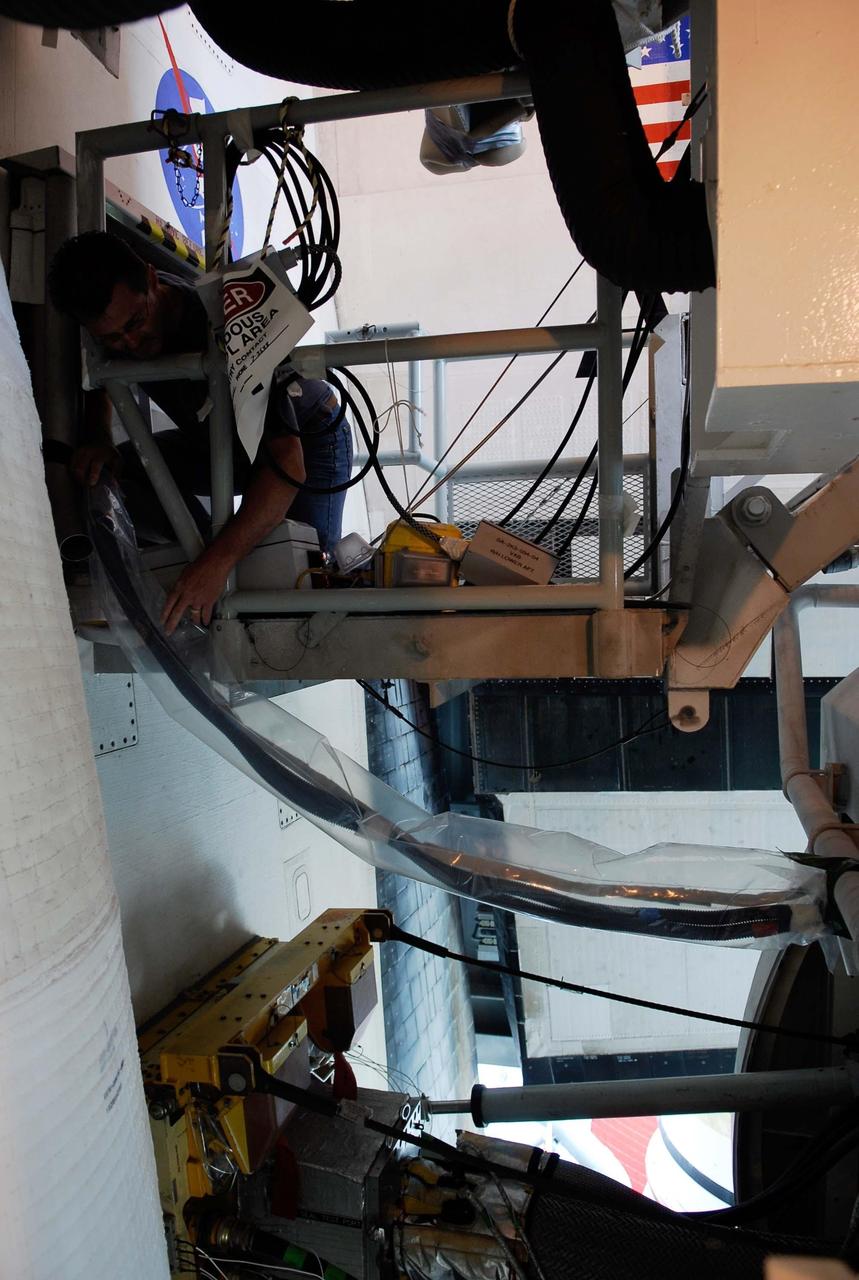
KENNEDY SPACE CENTER, FLA. -- On Launch Pad 39A, cables lead from an electrical harness in space shuttle Atlantis' aft main engine compartment connected with the engine cut-off, or ECO, system into the tail mast. The test wiring leads from the tail mast to the interior of the mobile launcher platform where the Time Domain Reflectometry, or TDR, test equipment will be located to test the sensor system. The shuttle's planned launches on Dec. 6 and Dec. 9 were postponed because of false readings from the part of the ECO system that monitors the liquid hydrogen section of the tank. The liftoff date from NASA's Kennedy Space Center, Florida, is now targeted for Jan. 10, depending on the resolution of the problem in the fuel sensor system. Photo credit: NASA/Kim Shiflett
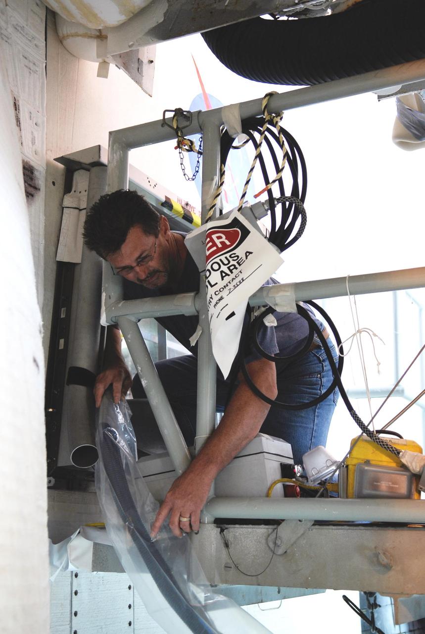
KENNEDY SPACE CENTER, FLA. -- On Launch Pad 39A, a technician prepares a cable from an electrical harness in space shuttle Atlantis' aft main engine compartment connected with the engine cut-off, or ECO, system leading into the tail mast. The test wiring leads from the tail mast to the interior of the mobile launcher platform where the Time Domain Reflectometry, or TDR, test equipment will be located to test the sensor system. The shuttle's planned launches on Dec. 6 and Dec. 9 were postponed because of false readings from the part of the ECO system that monitors the liquid hydrogen section of the tank. The liftoff date from NASA's Kennedy Space Center, Florida, is now targeted for Jan. 10, depending on the resolution of the problem in the fuel sensor system. Photo credit: NASA/Kim Shiflett
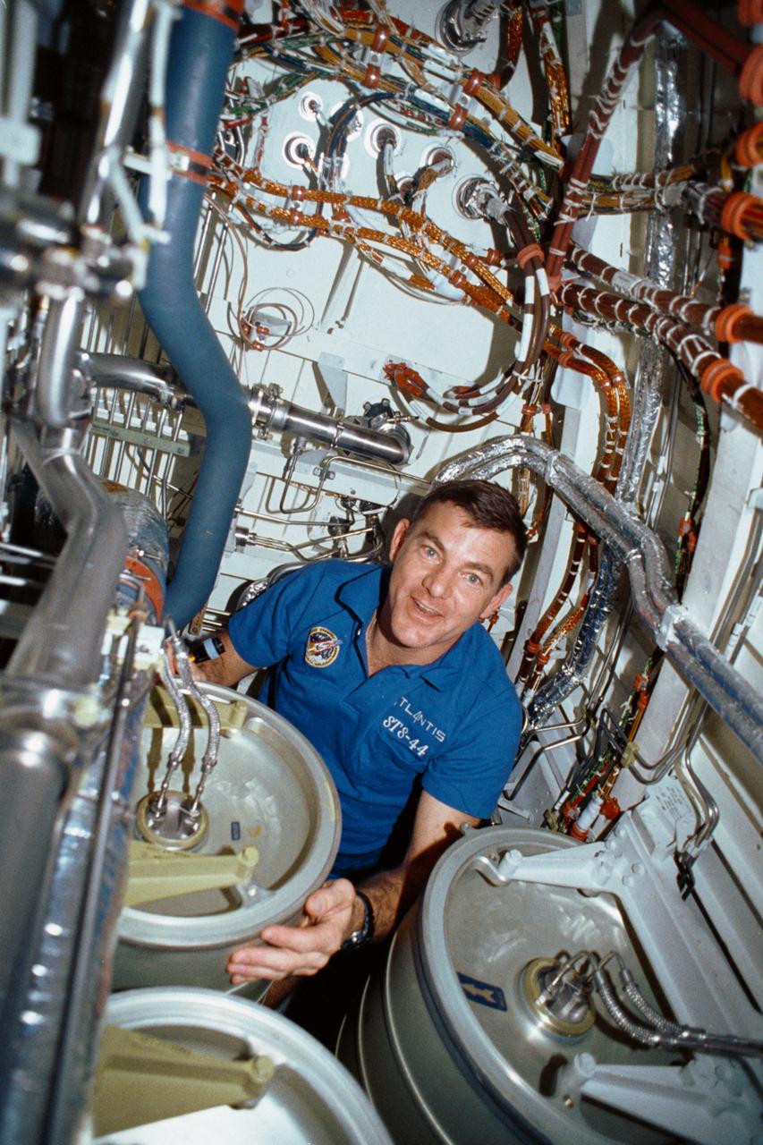
STS-44 Mission Specialist (MS) James S. Voss works under the middeck subfloor of Atlantis, Orbiter Vehicle (OV) 104, to repair humidity separator leakage problems. Voss is surrounded by several water tanks and a maze of shuttle wiring and plumbing. Voss earned the nickname of "Bilge Man" because of his time spent on the lower deck tending to the leakage problem. This is the first photo released of a crewmember in this area of the shuttle.
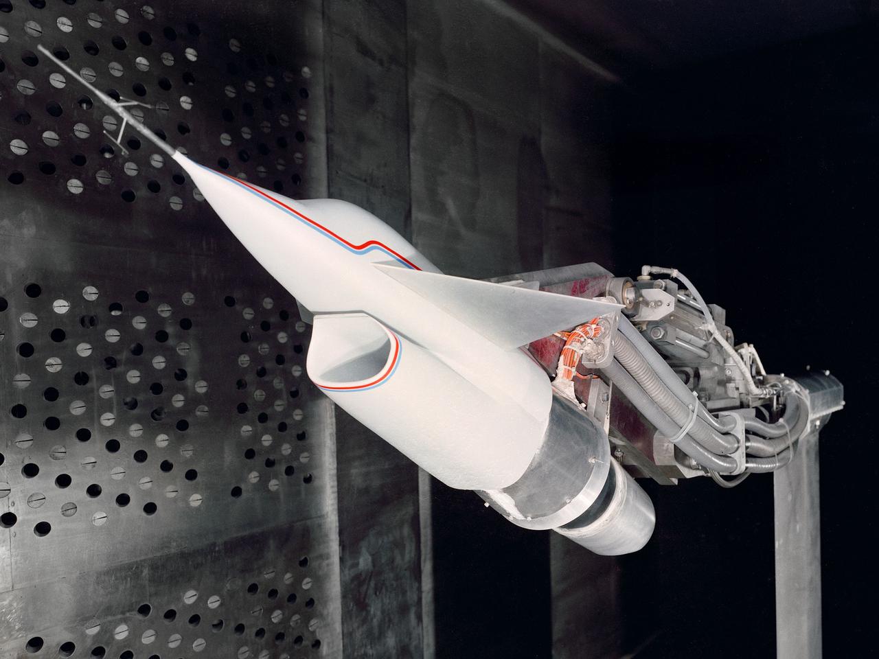
A Highly Maneuverable Aircraft Technology (HiMAT) inlet model installed in the test section of the 8- by 6-Foot Supersonic Wind Tunnel at the National Aeronautics and Space Administration (NASA) Lewis Research Center. Engineers at the Ames Research Center, Dryden Flight Research Center, and Rockwell International designed two pilotless subscale HiMAT vehicles in the mid-1970s to study new design concepts for fighter aircraft in the transonic realm without risking the lives of test pilots. The aircraft used sophisticated technologies such as advanced aerodynamics, composite materials, digital integrated propulsion control, and digital fly-by-wire control systems. In late 1977 NASA Lewis studied the HiMAT’s General Electric J85-21 jet engine in the Propulsion Systems Laboratory. The researchers charted the inlet quality with various combinations anti-distortion screens. HiMAT employed a relatively short and curved inlet compared to actual fighter jets. In the spring of 1979, Larry Smith led an in-depth analysis of the HiMAT inlet in the 8- by 6 tunnel. The researchers installed vortex generators to battle flow separation in the diffuser. The two HiMAT aircraft performed 11 hours of flying over the course of 26 missions from mid-1979 to January 1983 at Dryden and Ames. Although the HiMAT vehicles were considered to be overly complex and expensive, the program yielded a wealth of data that would validate computer-based design tools.
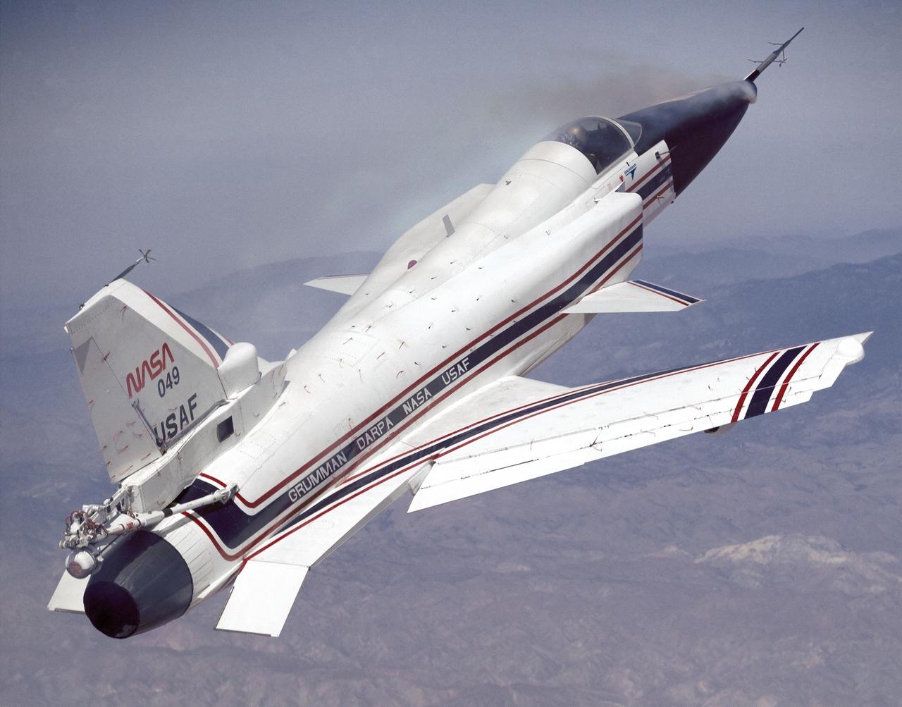
This photo shows the X-29 during a 1991 research flight. Smoke generators in the nose of the aircraft were used to help researchers see the behavior of the air flowing over the aircraft. The smoke here is demonstrating forebody vortex flow. This mission was flown September 10, 1991, by NASA research pilot Rogers Smith.
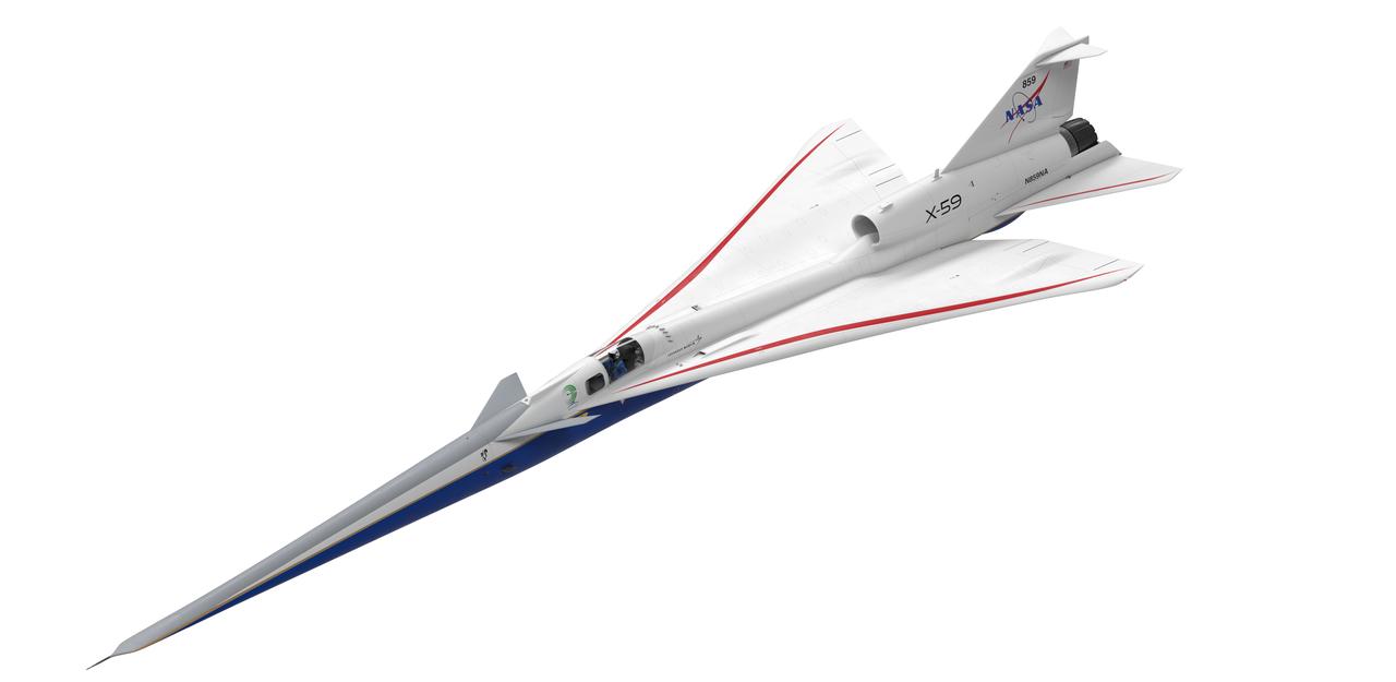
Artist concept of the X-59 three forths view top
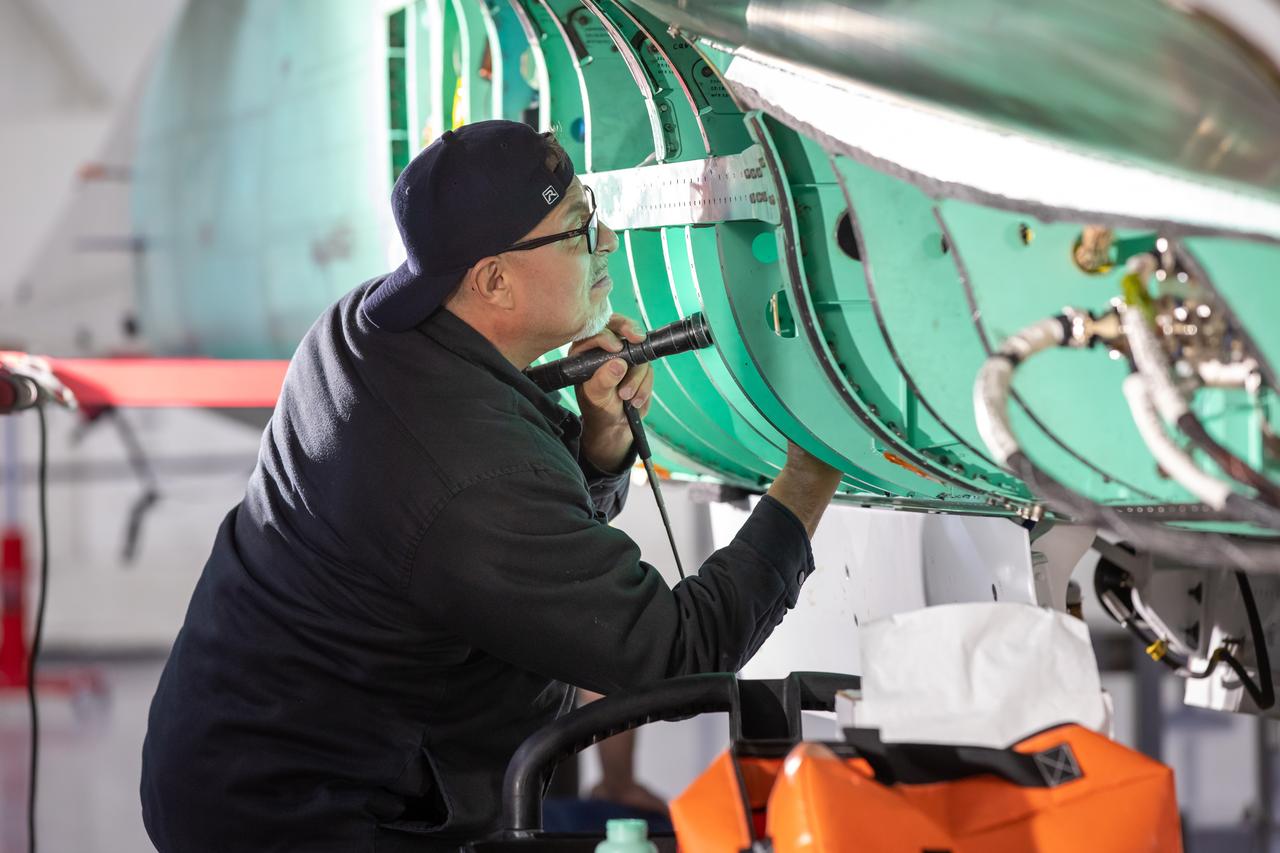
A quality inspector checks NASA’s X-59 aircraft during the construction phase. The X-59 was built in Lockheed Martin’s Skunk Works facility in Palmdale, California. Once the aircraft and ground testing are complete, the X-59 will undergo flight testing, which will demonstrate the plane’s ability to fly supersonic - faster than the speed of sound - while reducing the loud sonic boom. This could enable commercial supersonic air travel over land.
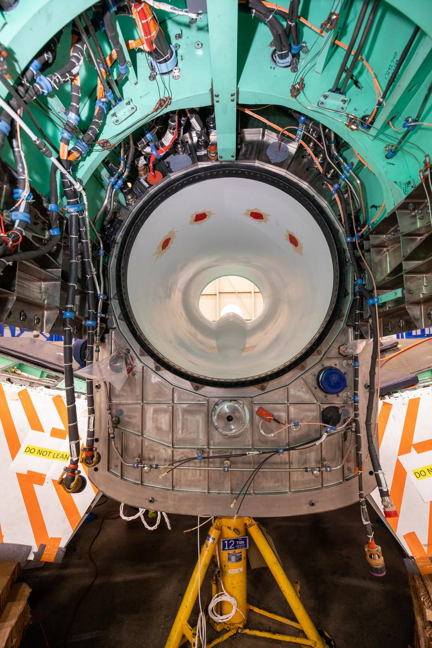
This image shows the X-59’s engine inlet from the aft view, which is the rear of the airplane, looking forward. Once the aircraft and ground testing are complete, the X-59 will undergo flight testing, which will demonstrate the plane’s ability to fly supersonic - faster than the speed of sound - while reducing the loud sonic boom. This could enable commercial supersonic air travel over land again.
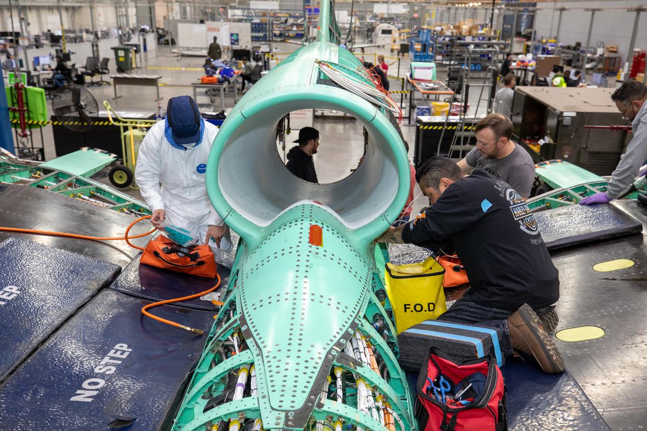
The X-59 team working on the aircraft’s wiring around the engine inlet prior to the engine being installed. Once complete, the X-59 is designed to fly supersonic while reducing the loud sonic boom. The Quesst mission could help change the rules for commercial supersonic air travel over land.
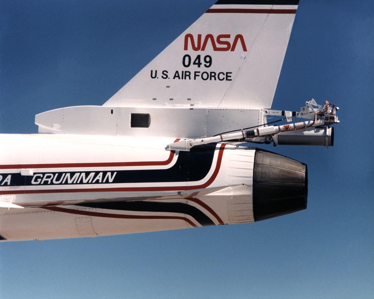
Because the number two X-29 at NASA's Ames-Dryden Flight Research Facility (later the Dryden Flight Research Center) flew at higher angles of attack than the number one aircraft, it required a spin chute system for safety. The system deployed a parachute for recovery of the aircraft if it inadvertently entered an uncontrolled spin. Most of the components of the spin chute system were located on a truss at the aft end of the aircraft. In addition, there were several cockpit modifications to facilitate use of the chute. The parachute was made of nylon and was of the conical ribbon type.

NASA Glenn Research Center has received the first of three Advanced Electric Propulsion System (AEPS) thrusters for the Gateway lunar space station. Built by L3Harris Technologies, the thruster will undergo testing before integration with Gateway’s Power and Propulsion Element, launching with the HALO module ahead of Artemis IV.