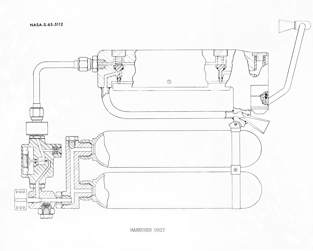
S65-05112 (30 May 1965) --- Cutaway engineering drawing showing some of the features of the zero-gravity integral propulsion unit.
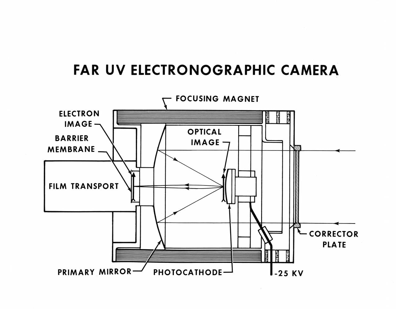
S73-36910 (November 1973) --- An engineer's drawing of the Skylab 4 Far Ultraviolet Electronographic camera (Experiment S201). Arrows point to various features and components of the camera. As the Comet Kohoutek streams through space at speeds of 100,000 miles per hour, the Skylab 4 crewmen will use the S201 UV camera to photograph features of the comet not visible from the Earth's surface. While the comet is some distance from the sun, the camera will be pointed through the scientific airlock in the wall of the Skylab space station Orbital Workshop (OWS). By using a movable mirror system built for the Ultraviolet Stellar Astronomy (S019) Experiment and rotating the space station, the S201 camera will be able to photograph the comet around the side of the space station. Photo credit: NASA
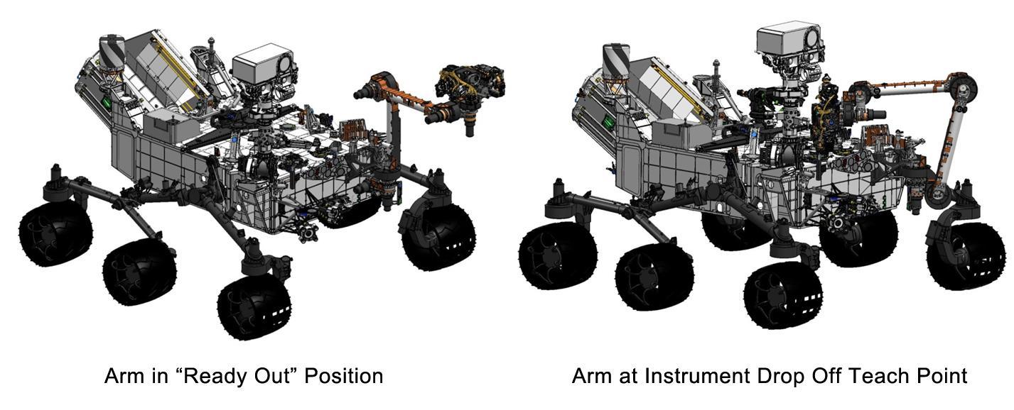
This engineering drawing shows the arm on NASA's Curiosity's rover in its "ready-for-action" position, or "ready out" as engineers say, in addition to the position it assumes to drop off samples. http://photojournal.jpl.nasa.gov/catalog/PIA16147
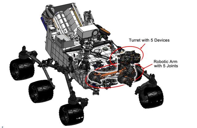
This engineering drawing shows the location of the arm on NASA Curiosity rover, in addition to the arm turret, which holds two instruments and three tools. The arm places and holds turret-mounted tools on rock and soil targets.
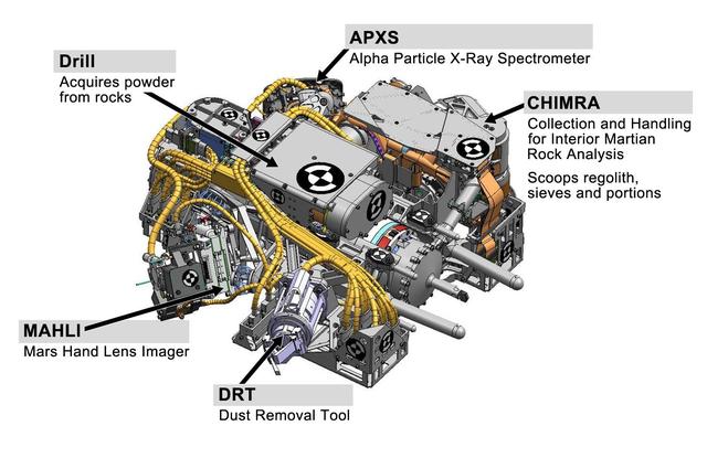
This engineering drawing shows the five devices that make up the turret at the end of the arm on NASA Curiosity rover. These include: the drill for acquiring powdered samples from interiors of rocks.
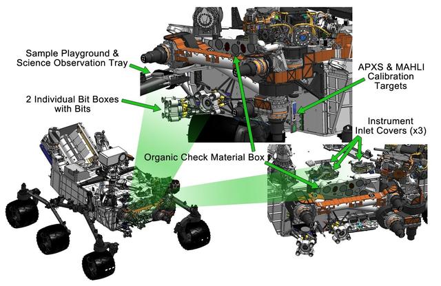
This engineering drawing shows various components needed to support tools at the end of the arm on NASA Curiosity rover, including: calibration targets for helping instruments set their baseline levels.
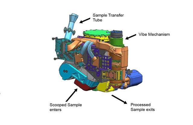
This false-color engineering drawing shows the Collection and Handling for In-Situ Martian Rock Analysis CHIMRA device, attached to the turret at the end of the robotic arm on NASA Curiosity Mars rover.
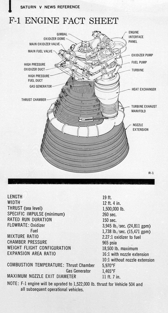
This figure is a drawing of the F-1 engine with callouts of the major components and the engine characteristics.

This figure is a line drawing of the J-2 engine with callouts of the major components and the engine characteristics.
This engineer's concept drawing of the A-3 Test Stand shows the 300-foot-tall structure's open steel frame and large exhaust diffuser.
![For me, I picked up an interest for engineering through drawing. When I was young, I was really big into art. Like most science-drawn younger kids, I would draw Pokémon, I would draw Dragon Ball Z, things like that. I guess my passion for art and drawing helped me to get into CAD (Computer Aided Design) modeling — things like 3D modeling and 3D printing. And with CAD modeling, you need to learn how to figure out the dimensions of things, what material they’re made out of, xyz. So that got me deeper into engineering. There’s definitely an artistic component to science. You can just look at James Webb [Space Telescope]. It looks artistic. If you look at the beveled mirrors, or how the bat wings on the side fold out, I would argue that that is artistic in a sense. But it also matches perfectly with its scientific functions. So not only does it need to fit into the rocket, but it also needs these beveled mirrors to reflect light at a specific angle. So, I think art and science blend pretty well. Kenneth Harris II, lead database engineer for the Joint Polar Satellite System (JPSS) J2 Satellite Mission at NASA’s Goddard Space Flight Center, Friday, Feb. 21, 2020, Greenbelt, Md. Photo Credit: (NASA/Joel Kowsky)](https://images-assets.nasa.gov/image/NHQ202002210002/NHQ202002210002~medium.jpg)
For me, I picked up an interest for engineering through drawing. When I was young, I was really big into art. Like most science-drawn younger kids, I would draw Pokémon, I would draw Dragon Ball Z, things like that. I guess my passion for art and drawing helped me to get into CAD (Computer Aided Design) modeling — things like 3D modeling and 3D printing. And with CAD modeling, you need to learn how to figure out the dimensions of things, what material they’re made out of, xyz. So that got me deeper into engineering. There’s definitely an artistic component to science. You can just look at James Webb [Space Telescope]. It looks artistic. If you look at the beveled mirrors, or how the bat wings on the side fold out, I would argue that that is artistic in a sense. But it also matches perfectly with its scientific functions. So not only does it need to fit into the rocket, but it also needs these beveled mirrors to reflect light at a specific angle. So, I think art and science blend pretty well. Kenneth Harris II, lead database engineer for the Joint Polar Satellite System (JPSS) J2 Satellite Mission at NASA’s Goddard Space Flight Center, Friday, Feb. 21, 2020, Greenbelt, Md. Photo Credit: (NASA/Joel Kowsky)
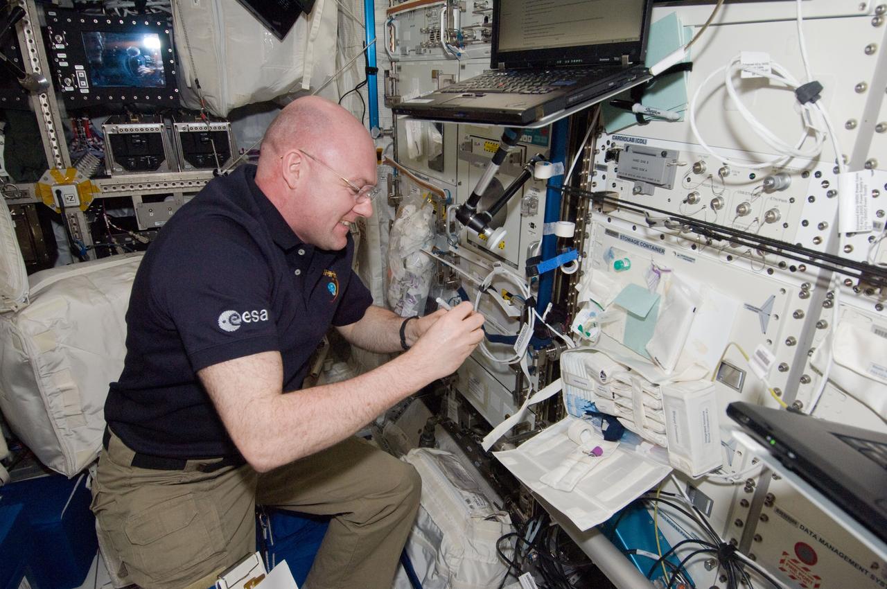
ISS030-E-257690 (26 April 2012) --- European Space Agency astronaut Andre Kuipers, Expedition 30 flight engineer, prepares for IMMUNE venous blood sample draws in the Columbus laboratory of the International Space Station. Following the blood draws, the samples were temporarily stowed in the Minus Eighty Laboratory Freezer for ISS 1 (MELFI-1) and later packed together with saliva samples on the Soyuz TMA-22 for return to Earth for analysis.
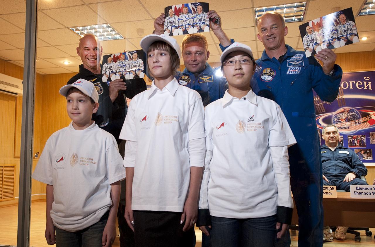
Spaceflight Participant Guy Laliberté, back left, Expedition 21 Flight Engineer Maxim Suraev, back center, Expedition 21 Flight Engineer Jeffrey N. Williams, back right, pose for a photograph with winners of a ROSCOSMOS drawing contest, Oleg Golovin, from Elektrostal, Russia, front left, Nastya Mestyashova from Orenburg, Russia, front center, and Dong Yue from China at the start of the press conference, Tuesday, Sept. 29, 2009 at the Cosmonaut Hotel in Baikonur, Kazakhstan. Their winning drawings will be incorporated into the Expedition 22 mission patch. Photo Credit: (NASA/Bill Ingalls)
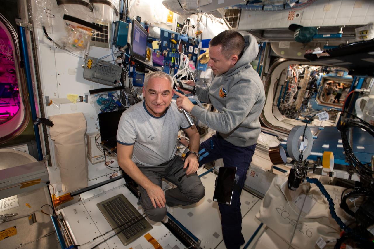
iss061e005754 (Oct. 13, 2019) --- NASA astronaut Andrew Morgan (right) took a break from his engineering and science duties aboard the International Space Station to trim the hair of Roscosmos cosmonaut Alexander Skvortsov. A vacuum is attached to the clippers that draws the loose hair in to keep the cabin atmosphere clean.
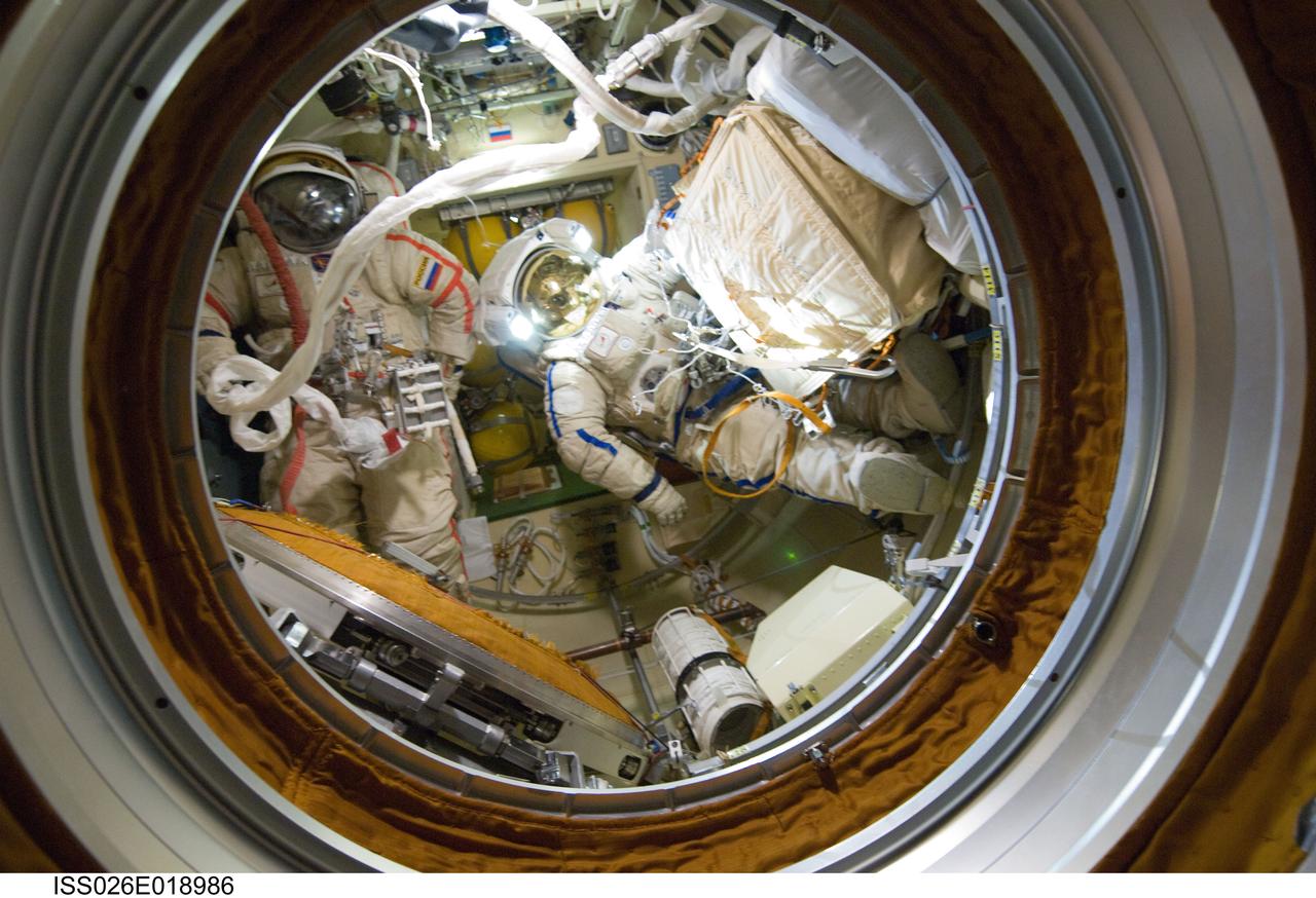
ISS026-E-018986 (21 Jan. 2011) --- Attired in their Russian Orlan spacesuits, Russian cosmonauts Dmitry Kondratyev (left) and Oleg Skripochka, both Expedition 26 flight engineers, are pictured in the Pirs Docking Compartment of the International Space Station as their session of extravehicular activity (EVA) draws to a close.
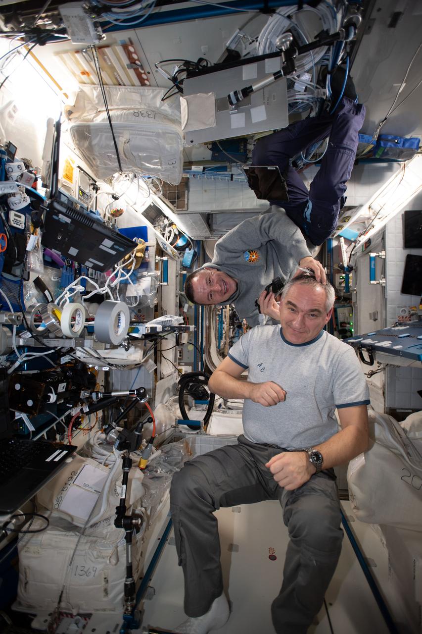
iss061e005740 (Oct. 13, 2019) --- NASA astronaut Andrew Morgan (right) took a break from his engineering and science duties aboard the International Space Station to trim the hair of Roscosmos cosmonaut Alexander Skvortsov. A vacuum is attached to the clippers that draws the loose hair in to keep the cabin atmosphere clean.
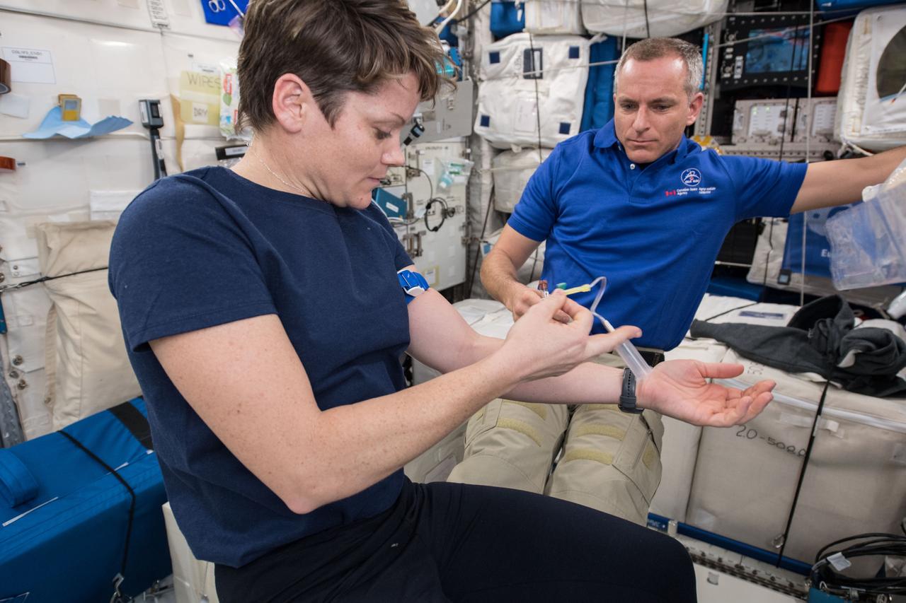
(12/8/2018) --- Flight Engineer (FE) Anne McClain prepares to draw her blood for the Marrow Study (Bone Marrow Adipose Reaction: Red Or White?). FE David Saint-Jacques assists. Photo was taken in the Columbus European Laboratory.
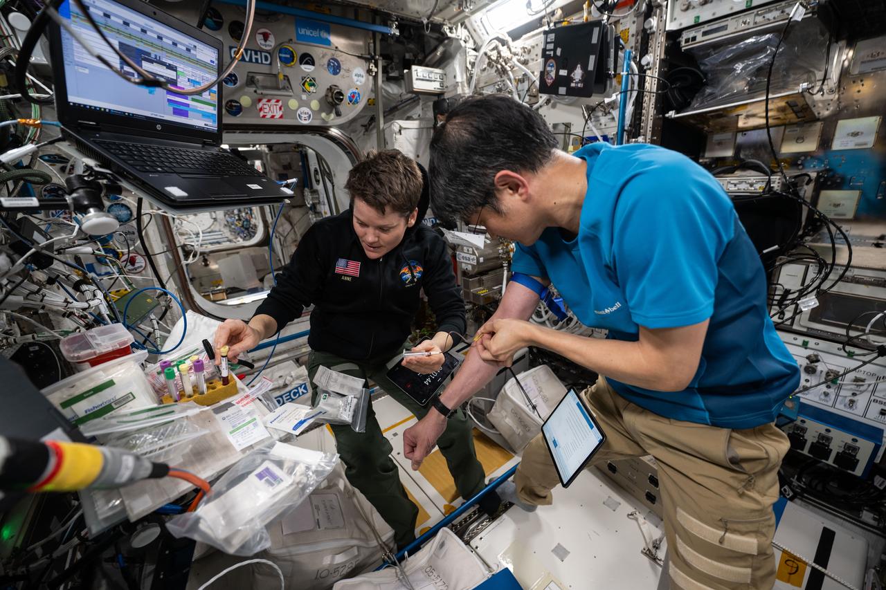
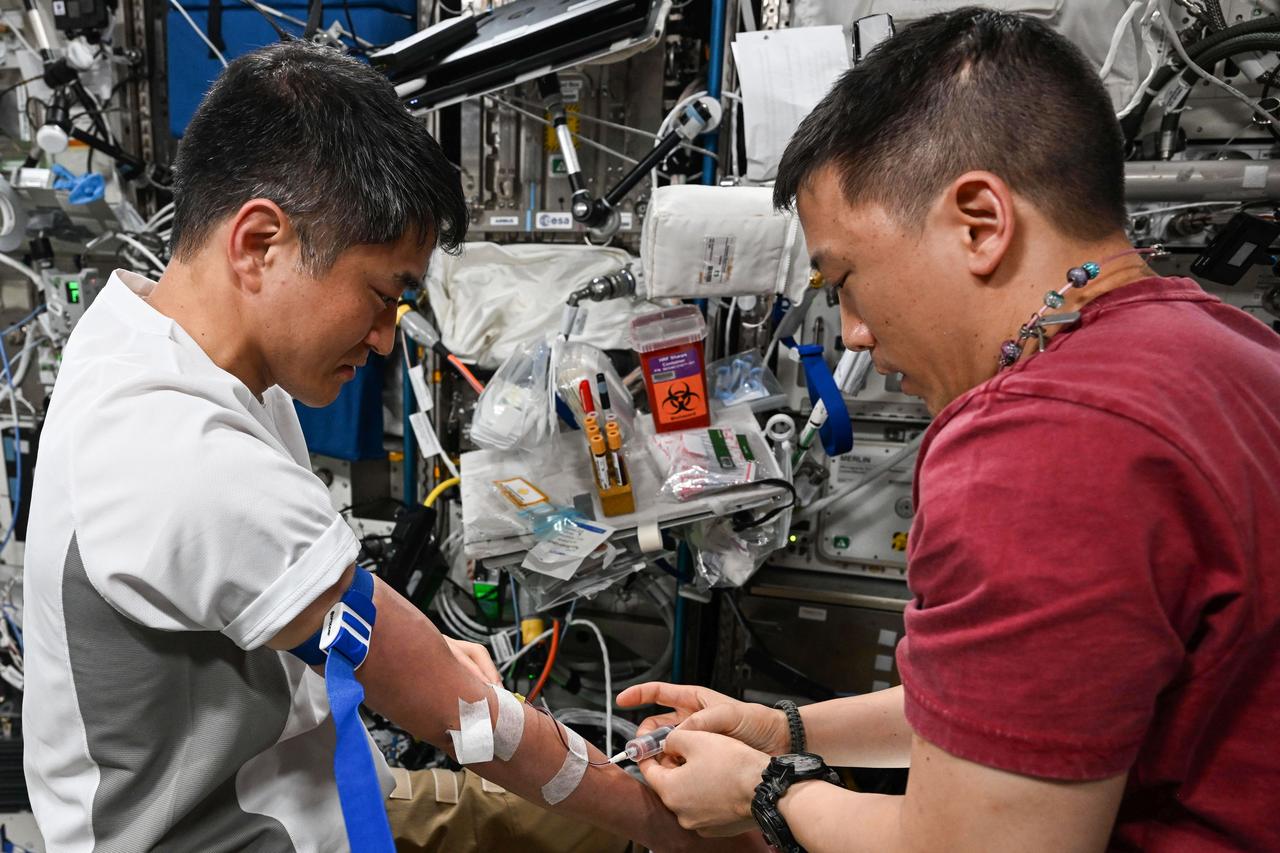
iss073e0078566 (May 23, 2025) --- Astronauts Anne McClain of NASA and Takuya Onishi of JAXA (Japan Aerospace Exploration Agency), Expedition 73 Flight Engineer and Commander respectively, work together inside the International Space Station's Columbus laboratory module drawing blood samples for testing and monitoring an astronaut's health in microgravity.
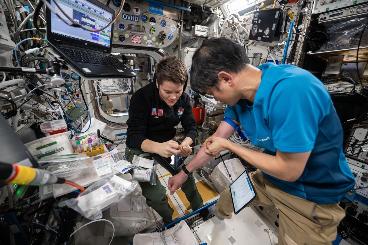
iss073e0078564 (May 23, 2025) --- Astronauts Anne McClain of NASA and Takuya Onishi of JAXA (Japan Aerospace Exploration Agency), Expedition 73 Flight Engineer and Commander respectively, work together inside the International Space Station's Columbus laboratory module drawing blood samples for testing and monitoring an astronaut's health in microgravity.
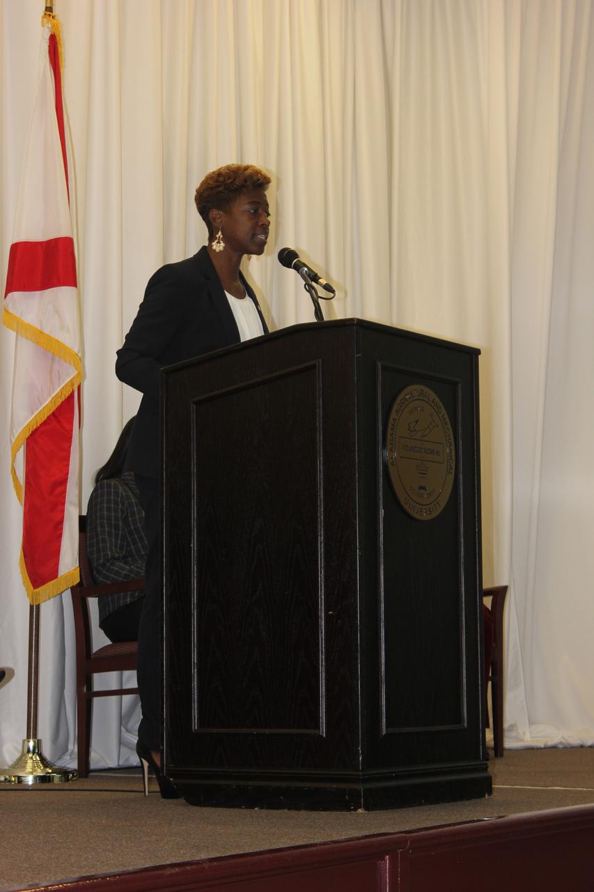
Marshall’s Ruth Jones, a mishap investigation specialist, told her NASA story and spoke about minority statistics in science, technology, engineering and mathematics (STEM). Jones also led a panel discussing how to engage, encourage and draw more minority students in to STEM fields and careers.
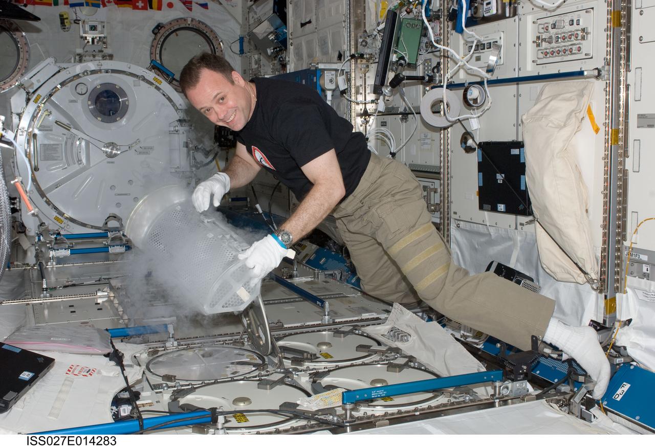
iss027e014283 (4/13/2011) --- Expedition 27 flight engineer Ron Garan prepares to stow a blood draw for the CSA (Canadian Space Agency) Vascular Blood Collection protocol in the Minus Eighty Laboratory Freezer for ISS (MELFI-1) in the Kibo laboratory of the International Space Station.
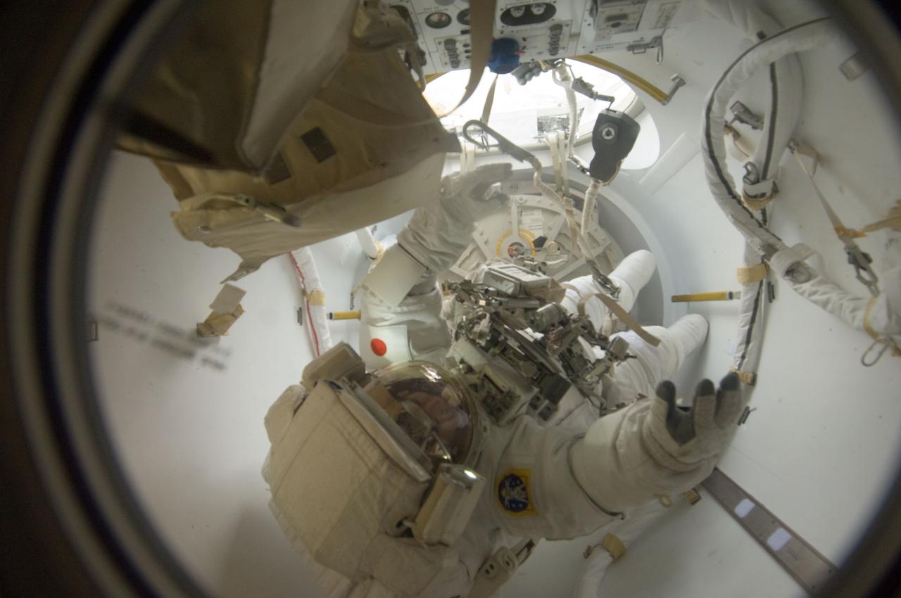
ISS033-E-018472 (1 Nov. 2012) --- Japan Aerospace Exploration Agency astronaut Aki Hoshide, Expedition 33 flight engineer, enters the International Space Station's Quest airlock as the session of extravehicular activity (EVA) draws to a close.
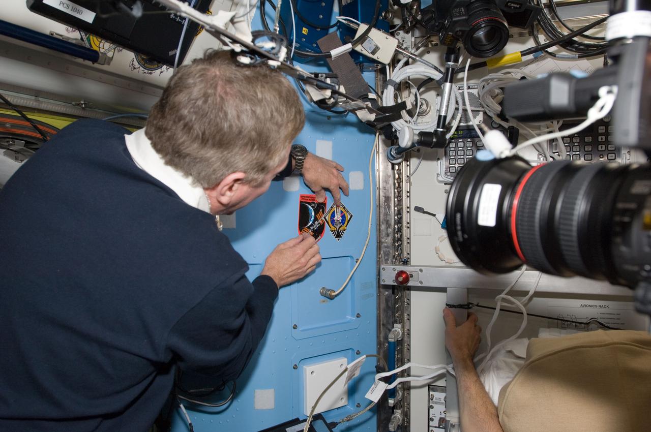
S135-E-009484 (18 July 2011) --- In the Quest airlock of the International Space Station, NASA astronaut Mike Fossum, Expedition 28 flight engineer, draws attention to the freshly posted STS-135 decal next to that of him and his five crewmates. Photo credit: NASA
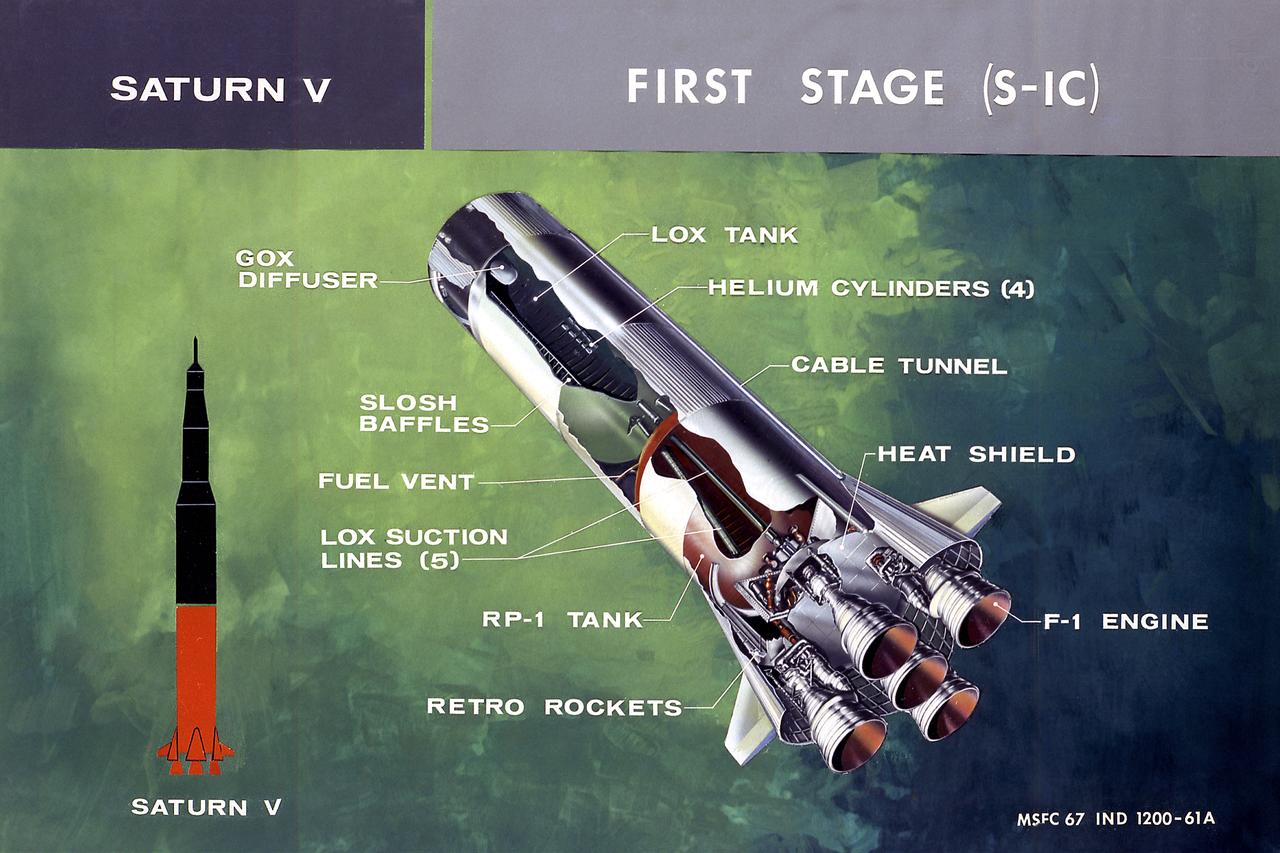
This illustration shows a cutaway drawing with callouts of the major components for the S-IC (first) stage of the Saturn V launch vehicle. The S-IC stage is 138 feet long and 33 feet in diameter, producing more than 7,500,000 pounds of thrust through five F-1 engines powered by liquid oxygen and kerosene. Four of the engines are mounted on an outer ring and gimball for control purposes. The fifth engine is rigidly mounted in the center. When ignited, the roar produced by the five engines equals the sound of 8,000,000 hi-fi sets.
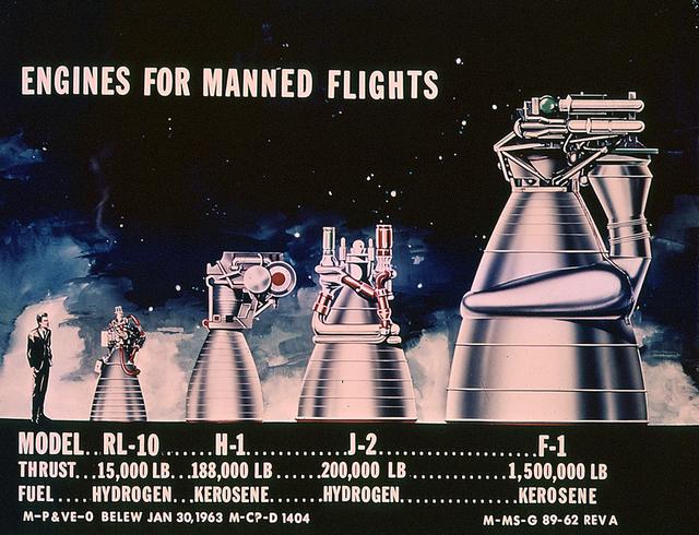
This drawing clearly shows the comparative sizes of the rocket engines used to launch the Saturn vehicles. The RL-10 and the H-1 engines were used to launch the Saturn I rockets. The J-2 engine was used on the second stage of Saturn IB and the second and third stages of Saturn V. The F-1 engine was used on the first stage of the Saturn V.
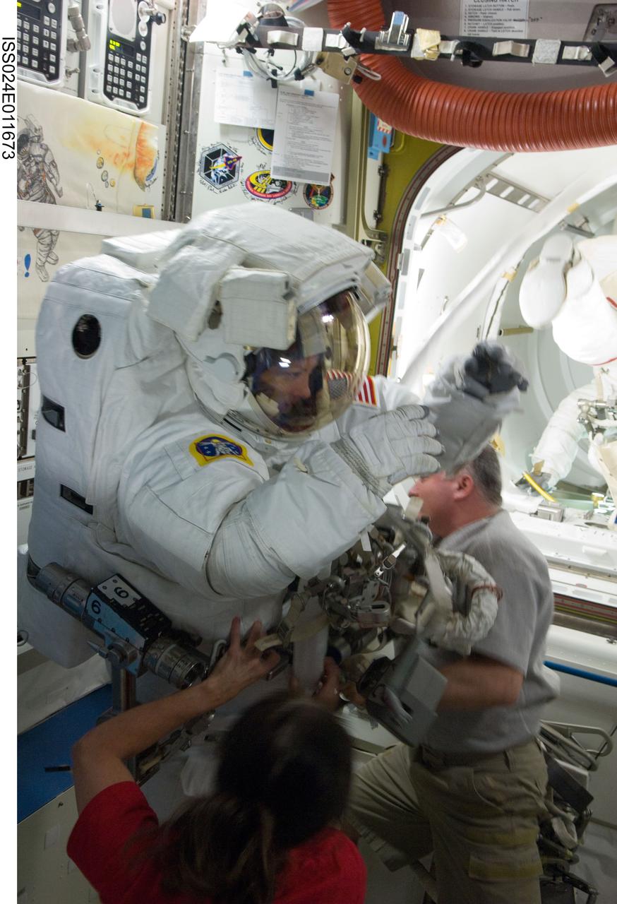
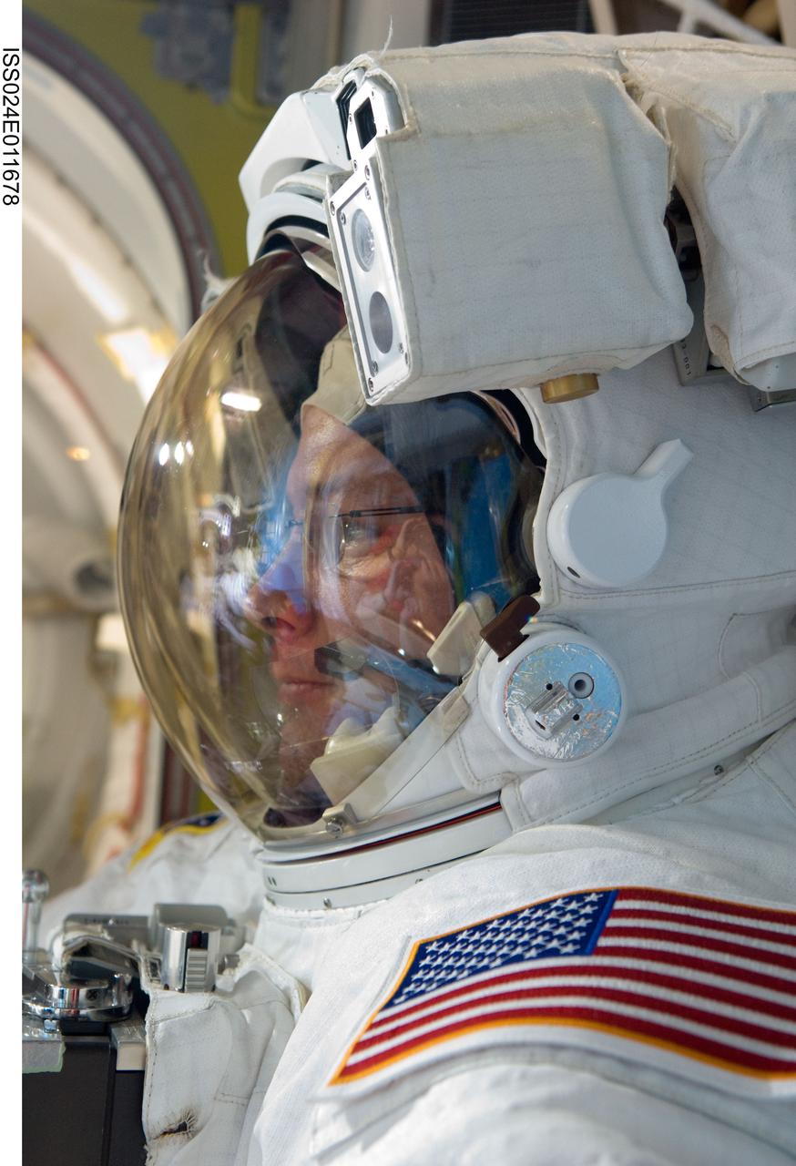
ISS024-E-011673 (11 Aug. 2010) --- NASA astronaut Tracy Caldwell Dyson, Expedition 24 flight engineer, attired in her Extravehicular Mobility Unit (EMU) spacesuit, is pictured in the Quest airlock of the International Space Station as the second of three planned spacewalks to remove and replace an ammonia pump module that failed July 31 draws to a close. NASA astronaut Shannon Walker and Russian cosmonaut Fyodor Yurchikhin, both flight engineers, assist Caldwell Dyson with the doffing of her spacesuit.
ISS018-E-041411 (21 March 2009) --- Astronaut Tony Antonelli (left), STS-119 pilot; and Japan Aerospace Exploration Agency (JAXA) astronaut Koichi Wakata, Expedition 18 flight engineer, assist astronaut Steve Swanson and Joseph Acaba (out of frame), both STS-119 mission specialists, as they return to the Quest Airlock of the International Space Station as the mission?s second session of extravehicular activity (EVA) draws to a close.
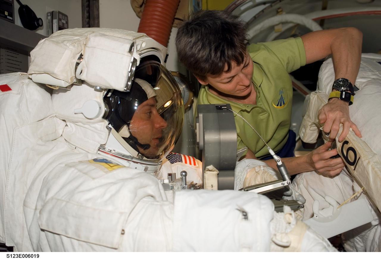
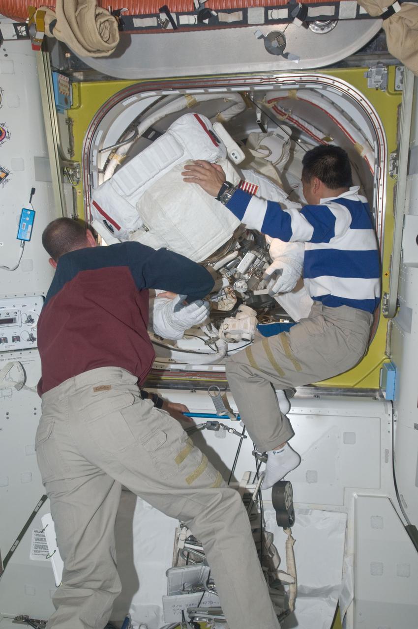
S123-E-006019 (14 March 2008) --- Astronaut Peggy Whitson, Expedition 16 commander, assists astronauts Garrett Reisman, Expedition 16 flight engineer, and Rick Linnehan (partially out of frame), STS-123 mission specialist, in doffing their Extravehicular Mobility Unit (EMU) spacesuits in the Quest Airlock of the International Space Station as the mission's first session of extravehicular activity (EVA) draws to a close.
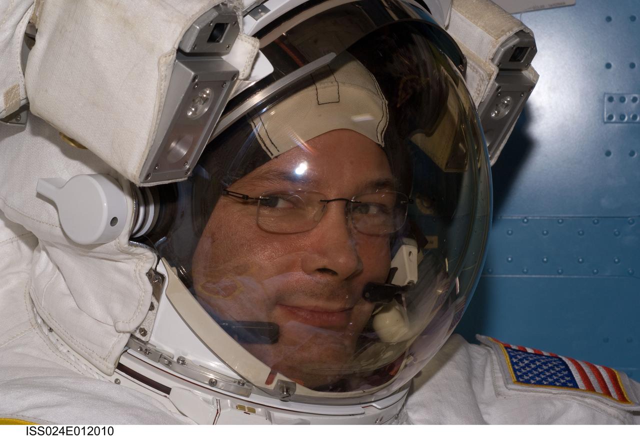
ISS024-E-012010 (16 Aug. 2010) --- NASA astronaut Doug Wheelock, Expedition 24 flight engineer, attired in his Extravehicular Mobility Unit (EMU) spacesuit, is pictured in the Quest airlock of the International Space Station as the final of three planned spacewalks to remove and replace an ammonia pump module that failed July 31 draws to a close.
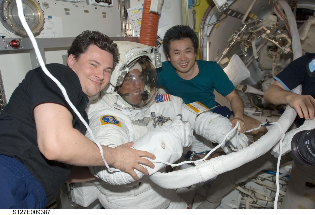
S127-E-009387 (27 July 2009) --- Attired in his Extravehicular Mobility Unit (EMU) spacesuit, astronaut Christopher Cassidy, STS-127 mission specialist, is pictured in the Quest Airlock of the International Space Station as the mission's fifth and final session of extravehicular activity (EVA) draws to a close. Cosmonaut Roman Romanenko (left), Expedition 20 flight engineer; and Japan Aerospace Exploration Agency (JAXA) astronaut Koichi Wakata, mission specialist, assist with the doffing of the spacesuit.
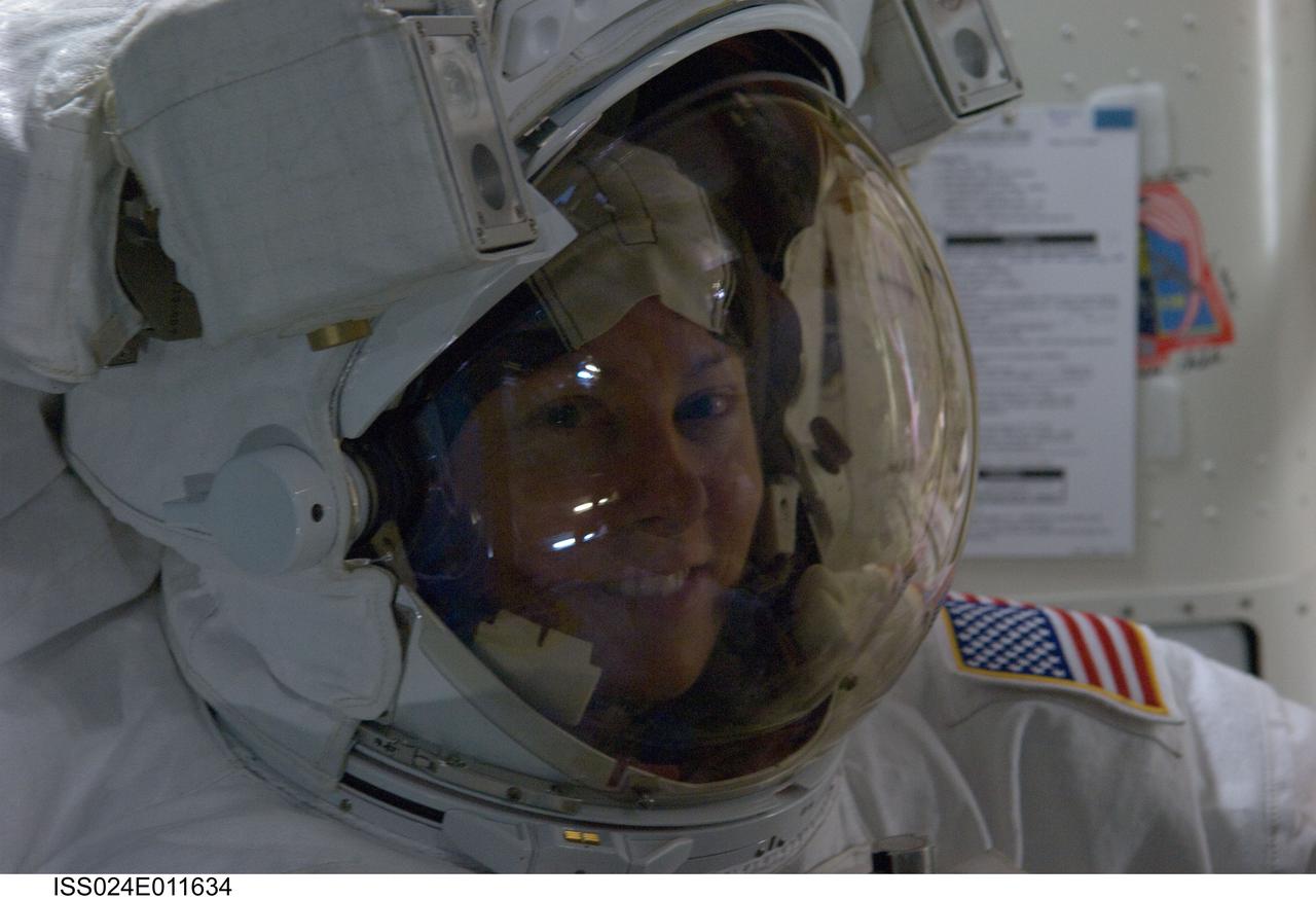
ISS024-E-011634 (7 Aug. 2010) --- Attired in her Extravehicular Mobility Unit (EMU) spacesuit, NASA astronaut Tracy Caldwell Dyson, Expedition 24 flight engineer, is pictured in the Quest airlock of the International Space Station as the first of three planned spacewalks to remove and replace an ammonia pump module that failed July 31 draws to a close.
iss073e0384171 (July 1, 2025) --- Expedition 73 Flight Engineer Jonny Kim (right) of NASA draws a blood sample from station Commander Takuya Onishi of JAXA (Japan Aerospace Exploration Agency) for processing in a centrifuge and preservation in a science freezer. The samples will be returned to Earth where scientists will analyze the specimens to learn how living and working in microgravity affects the human body and provide countermeasures to potential space-caused symptoms.
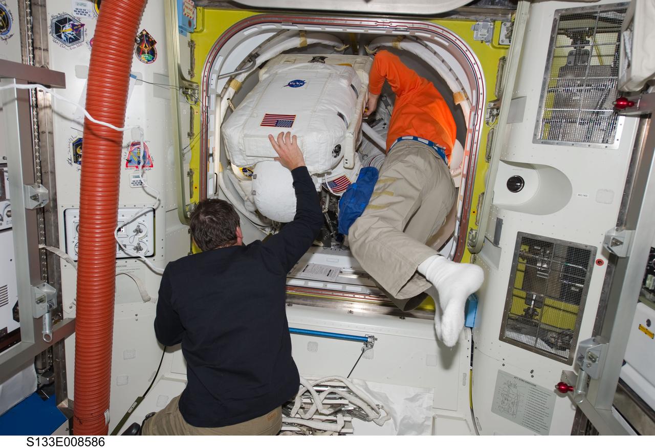
S133-E-008586 (2 March 2011) --- Attired in his Extravehicular Mobility Unit (EMU) spacesuit, NASA astronaut Alvin Drew, STS-133 mission specialist, enters the International Space Station's Quest airlock as the mission's second spacewalk draws to a close. NASA astronaut Michael Barratt (left), STS-133 mission specialist; and European Space Agency astronaut Paolo Nespoli, Expedition 26 flight engineer, assisted Drew. Photo credit: NASA or National Aeronautics and Space Administration
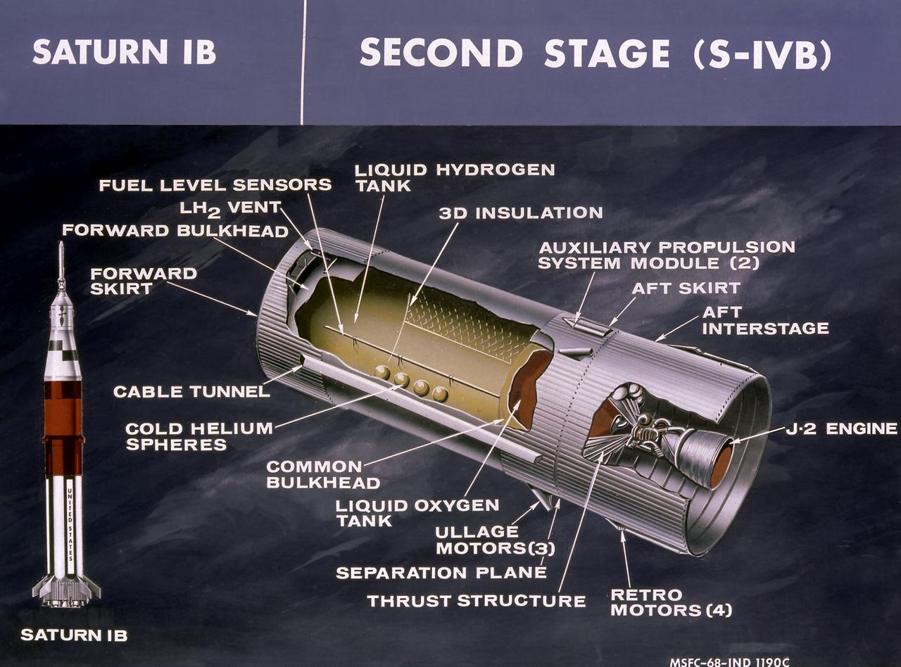
This cutaway drawing shows the S-IVB stage in its Saturn IB configuration. As a part of the Marshall Space Flight Center's (MSFC) "building block" approach to the Saturn development, the S-IVB stage was utilized in the Saturn IB launch vehicle as a second stage and, later, the Saturn V launch vehicle as a third stage. The stage was powered by a single J-2 engine, initially capable of 200,000 pounds of thrust.
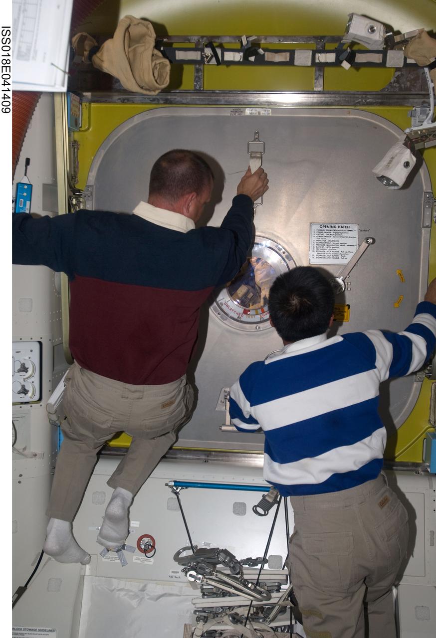
ISS018-E-041409 (21 March 2009) --- Astronaut Tony Antonelli (left), STS-119 pilot; and Japan Aerospace Exploration Agency (JAXA) astronaut Koichi Wakata, Expedition 18 flight engineer, prepare to open the hatch door in the Quest Airlock of the International Space Station for the returning spacewalkers as the mission?s second session of extravehicular activity (EVA) draws to a close.
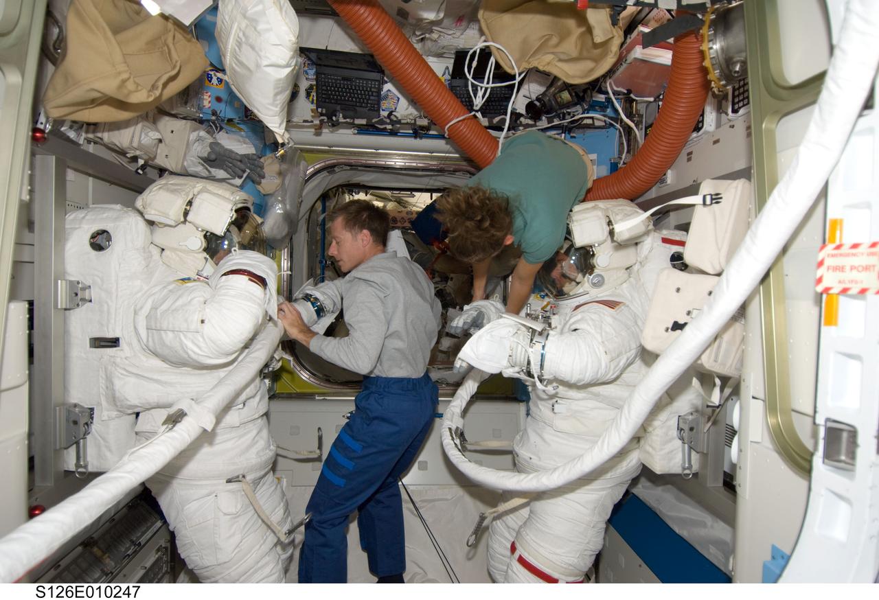
S126-E-010247 (24 Nov. 2008) --- Astronauts Steve Bowen (left) and Shane Kimbrough, both STS-126 mission specialists, attired in their Extravehicular Mobility Unit (EMU) spacesuits, are pictured in the Quest Airlock of the International Space Station as the mission's fourth session of extravehicular activity (EVA) draws to a close. Astronauts Chris Ferguson, commander; and Sandra Magnus, Expedition 18 flight engineer, assist with the doffing of the spacesuits.

Representatives of the state of Alabama, academia, and industry listen and take part in a panel discussion led by NASA Marshall Space Flight Center's Ruth Jones as part of the first Alabama Historically Black Colleges and Universities Roundtable Discussion. The event focused on drawing more minorities, specifically women, into academic fields and careers in science, technology, engineering and mathematics.
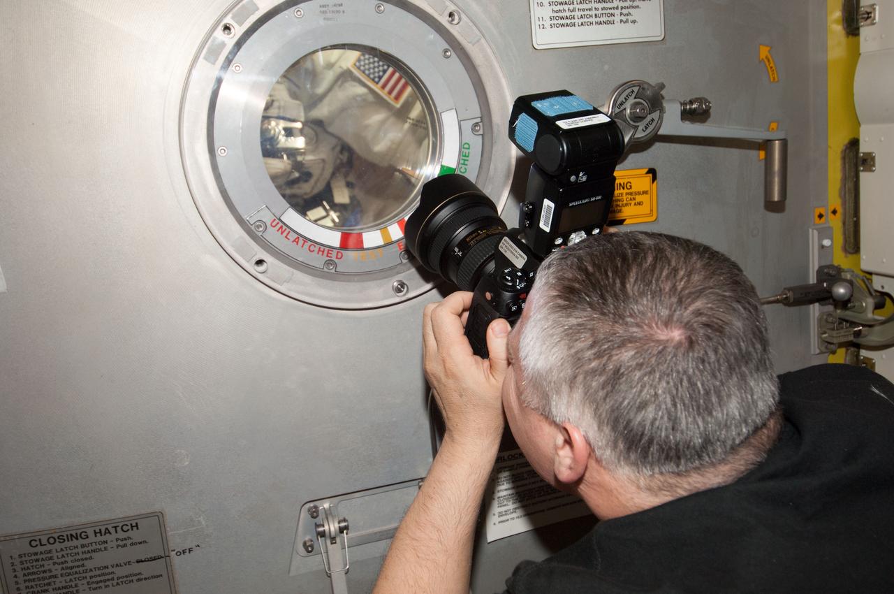
ISS036-E-019889 (16 July 2013) --- Russian cosmonaut Fyodor Yurchikhin, Expedition 36 flight engineer, uses a digital still camera at a hatch window of the International Space Station’s Quest airlock to photograph European Space Agency astronaut Luca Parmitano and NASA astronaut Chris Cassidy as the July 16 spacewalk draws to a close. The spacewalk was ended early due to issues with Parmitano’s spacesuit.
S123-E-006031 (14 March 2008) --- As the mission's first session of extravehicular activity (EVA) draws to a close, astronaut Peggy Whitson, Expedition 16 commander, photographs the Extravehicular Mobility Unit (EMU) gloves worn by astronauts Garrett Reisman (left), Expedition 16 flight engineer; and Rick Linnehan, STS-123 mission specialist, in the Quest Airlock of the International Space Station.
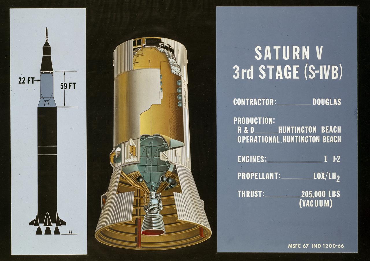
This cutaway drawing shows the S-IVB (third stage) of the Saturn V launch vehicle. As a part of the Marshall Space Flight Center’s (MSFC) “building block” approach to the Saturn development, the S-IVB stage was utilized in the Saturn IB launch vehicle as a second stage and, later, the Saturn V launch vehicle as a third stage. The 59 foot long and 22 feet diameter stage was powered by a single J-2 engine, initially capable of 200,000 pounds of thrust.
ISS020-E-025698 (27 July 2009) --- Attired in his Extravehicular Mobility Unit (EMU) spacesuit, astronaut Christopher Cassidy, STS-127 mission specialist; along with cosmonaut Roman Romanenko (left), Expedition 20 flight engineer; and Japan Aerospace Exploration Agency (JAXA) astronaut Koichi Wakata, mission specialist, are pictured in the Quest Airlock of the International Space Station as the mission's fifth and final session of extravehicular activity (EVA) draws to a close.
The cutaway drawing of the A-4 (Aggregate-4) rocket. Later renamed the V-2 (Vengeance Weapon-2), The rocket was developed by Dr. Wernher von Braun and the German rocket team at Peenemuende, Germany on the Baltic Sea. At the end of World War II, the team of German engineers and scientists came to the United States and continued rocket research for the Army at Fort Bliss, Texas, and Redstone Arsenal in Huntsville, Alabama.
ISS024-E-011678 (11 Aug. 2010) --- NASA astronaut Doug Wheelock, Expedition 24 flight engineer, attired in his Extravehicular Mobility Unit (EMU) spacesuit, is pictured in the Quest airlock of the International Space Station as the second of three planned spacewalks to remove and replace an ammonia pump module that failed July 31 draws to a close.
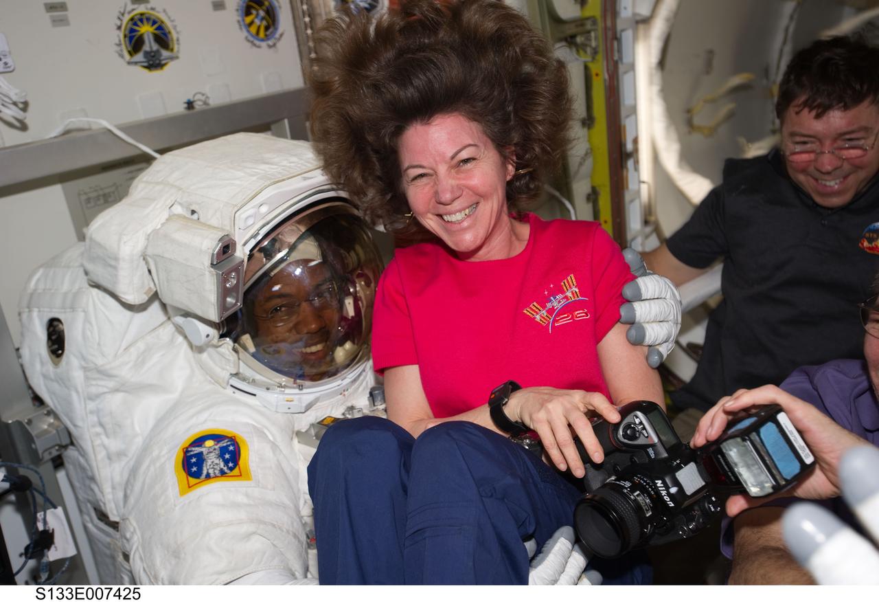
S133-E-007425 (28 Feb. 2011) --- NASA astronauts Cady Coleman, Expedition 26 flight engineer, Alvin Drew and Michael Barratt (background), both STS-133 mission specialists, enjoy a light moment in the Quest airlock of the International Space Station as the mission?s first spacewalk draws to a close. Photo credit: NASA or National Aeronautics and Space Administration
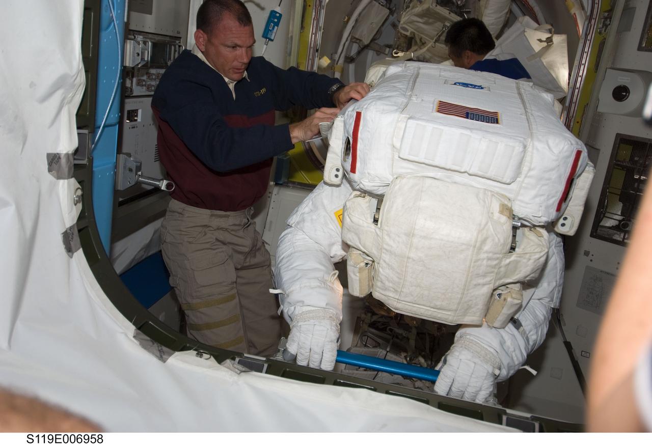
S119-E-006958 (21 March 2009) --- Astronauts Tony Antonelli (left), STS-119 pilot; and Japan Aerospace Exploration Agency’s (JAXA) Koichi Wakata (background), Expedition 18 flight engineer, assist astronauts Steve Swanson (foreground) and Joseph Acaba (totally obscured), both mission specialists, as they return to the Quest Airlock of the International Space Station as the mission’s second session of extravehicular activity (EVA) draws to a close.
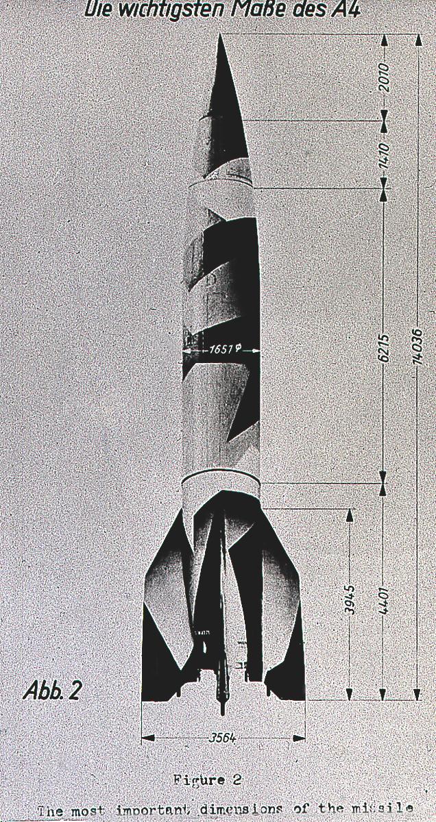
This drawing illustrates the vital dimensions of the A-4 (Aggregate-4). Later renamed the V-2 (Vengeance Weapon-2), the rocket was developed by Dr. Wernher von Braun and the German rocket team at Peenemuende, Germany on the Baltic Sea. At the end of World War II, the team of German engineers and scientists came to the United States and continued rocket research for the Army at Fort Bliss, Texas, and Redstone Arsenal in Huntsville, Alabama.
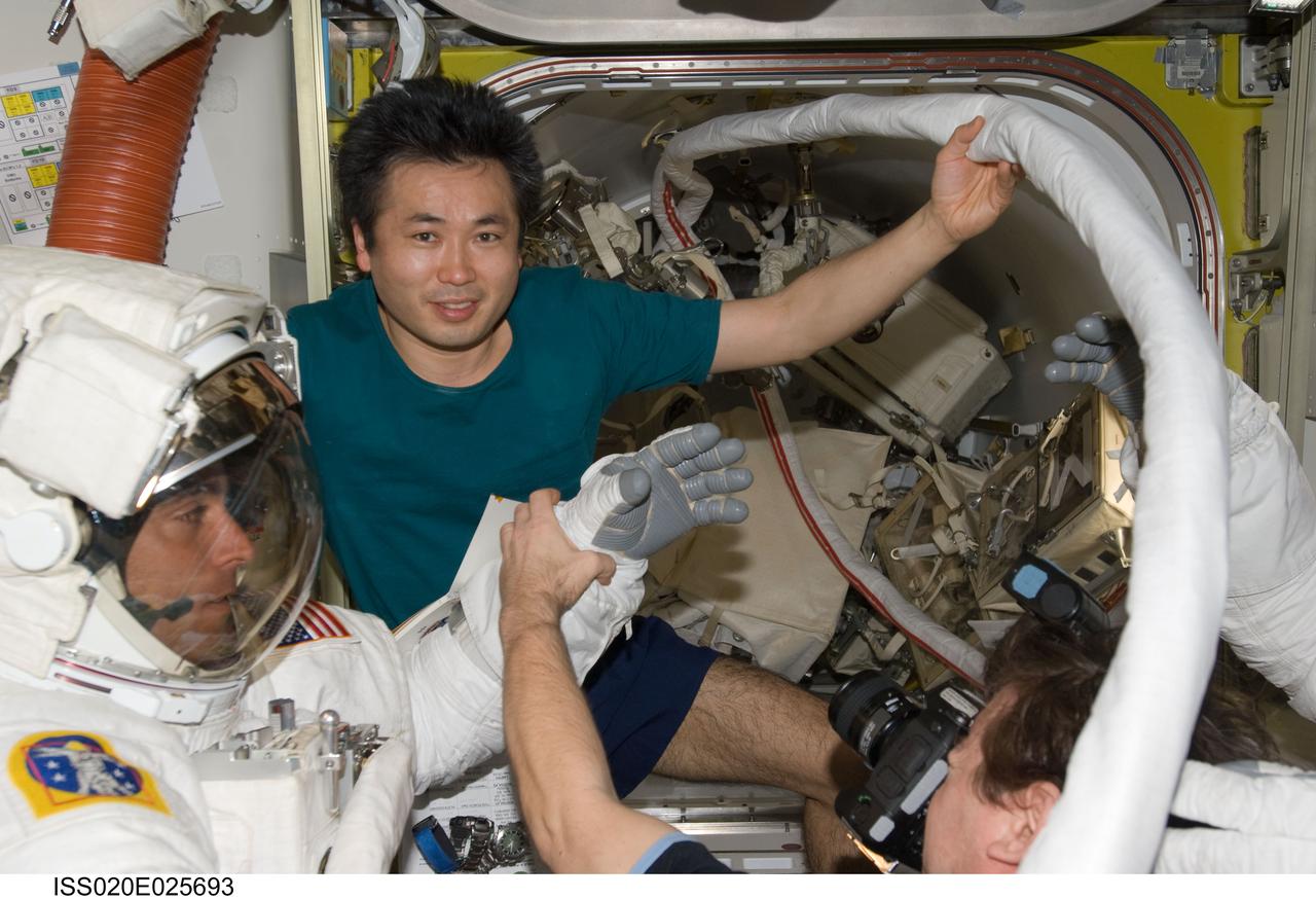
ISS020-E-025693 (27 July 2009) --- Attired in his Extravehicular Mobility Unit (EMU) spacesuit, astronaut Christopher Cassidy, STS-127 mission specialist, is pictured in the Quest Airlock of the International Space Station as the mission's fifth and final session of extravehicular activity (EVA) draws to a close. Astronaut Michael Barratt, Expedition 20 flight engineer, photographs the EMU gloves worn by Cassidy while Japan Aerospace Exploration Agency (JAXA) astronaut Koichi Wakata, mission specialist, assists with the doffing of the spacesuit.
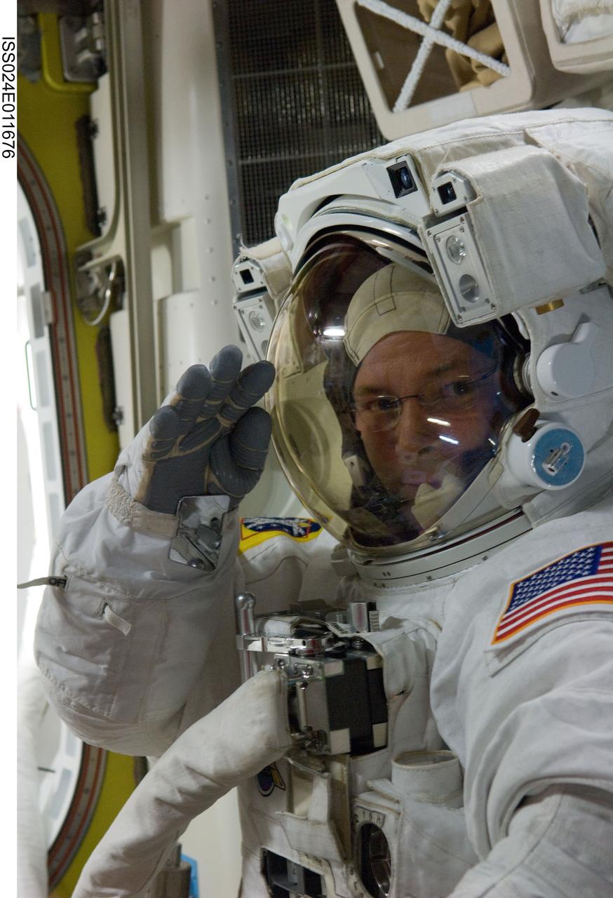
ISS024-E-011676 (11 Aug. 2010) --- NASA astronaut Doug Wheelock, Expedition 24 flight engineer, attired in his Extravehicular Mobility Unit (EMU) spacesuit, is pictured in the Quest airlock of the International Space Station as the second of three planned spacewalks to remove and replace an ammonia pump module that failed July 31 draws to a close.
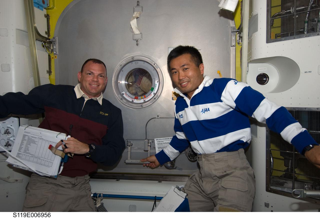
S119-E-006956 (21 March 2009) --- NASA astronaut Tony Antonelli (left), STS-119 pilot; and Japan Aerospace Exploration Agency (JAXA) astronaut Koichi Wakata, Expedition 18 flight engineer, are pictured in the Quest Airlock of the International Space Station while Space Shuttle Discovery remains docked with the station. They are about to open the hatch for Steve Swanson and Joseph Acaba, mission specialists, as they return to the station’s Quest Airlock as the mission’s second session of extravehicular activity (EVA) draws to a close.
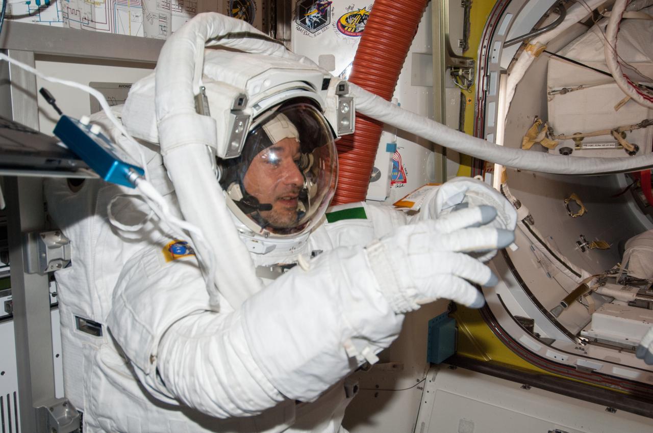
ISS036-E-019886 (16 July 2013) --- European Space Agency astronaut Luca Parmitano, Expedition 36 flight engineer, attired in an Extravehicular Mobility Unit (EMU) spacesuit, is pictured in the International Space Station’s Quest airlock as the July 16 spacewalk draws to a close. A little more than one hour into the spacewalk, Parmitano reported water floating behind his head inside his helmet. The water was not an immediate health hazard for Parmitano, but Mission Control decided to end the spacewalk early.
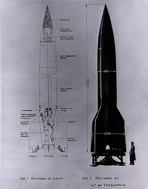
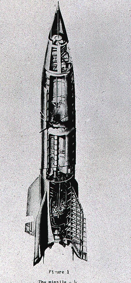
This German cutaway drawing of the Aggregate-4 (A-4) illustrates the dimensions and internal workings of the rocket. Later renamed the V-2, the rocket was developed by Dr. Wernher von Braun and the German Rocket Team at Peenemuende on the Baltic Sea. At the end of World War II, the team of German engineers and scientists came to the United States to work for the Army at Fort Bliss, Texas, and Redstone Arsenal in Huntsville, Alabama.
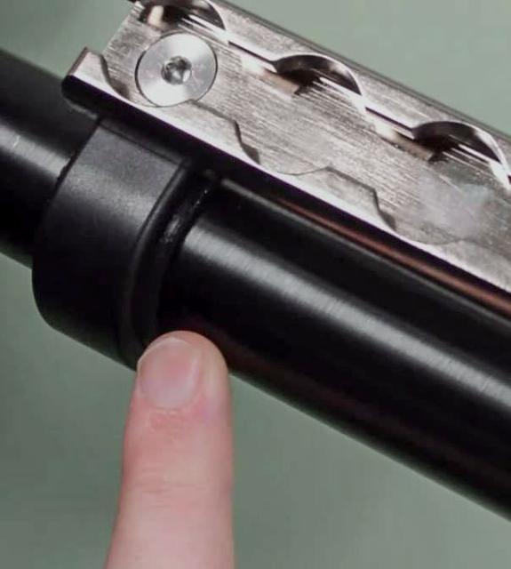
jsc2023e010183 (2/28/2023) --- The High school students United with NASA to Create Hardware (HUNCH) Ball Clamp Monopod (HUNCH Ball Clamp Monopod) investigation aims to test a temporary but stable platform for holding cameras, making camera operations easier and faster for the International Space Station crew. This hardware was designed and developed by HUNCH students using engineering design processes. They produced elements such as Computer Aided Design (CAD) drawings, CAD study models, and 3D printed engineering evaluation units on parts such as this insert that allow the seat track clamp to be positioned. Image courtesy of HUNCH.
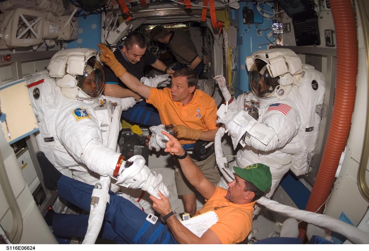
S116-E-06624 (16 Dec. 2006) --- As the mission's third spacewalk draws to a close, astronauts Robert L. Curbeam, Jr. (left), STS-116 mission specialist, and Sunita L. Williams, Expedition 14 flight engineer, get help as they remove their extravehicular mobility unit (EMU) spacesuits in the Quest Airlock of the International Space Station. Astronaut William A. (Bill) Oefelein (bottom), pilot; European Space Agency (ESA) astronaut Christer Fuglesang, mission specialist; and cosmonaut Mikhail Tyurin, Expedition 14 flight engineer representing Russia's Federal Space Agency, assisted Curbeam and Williams.
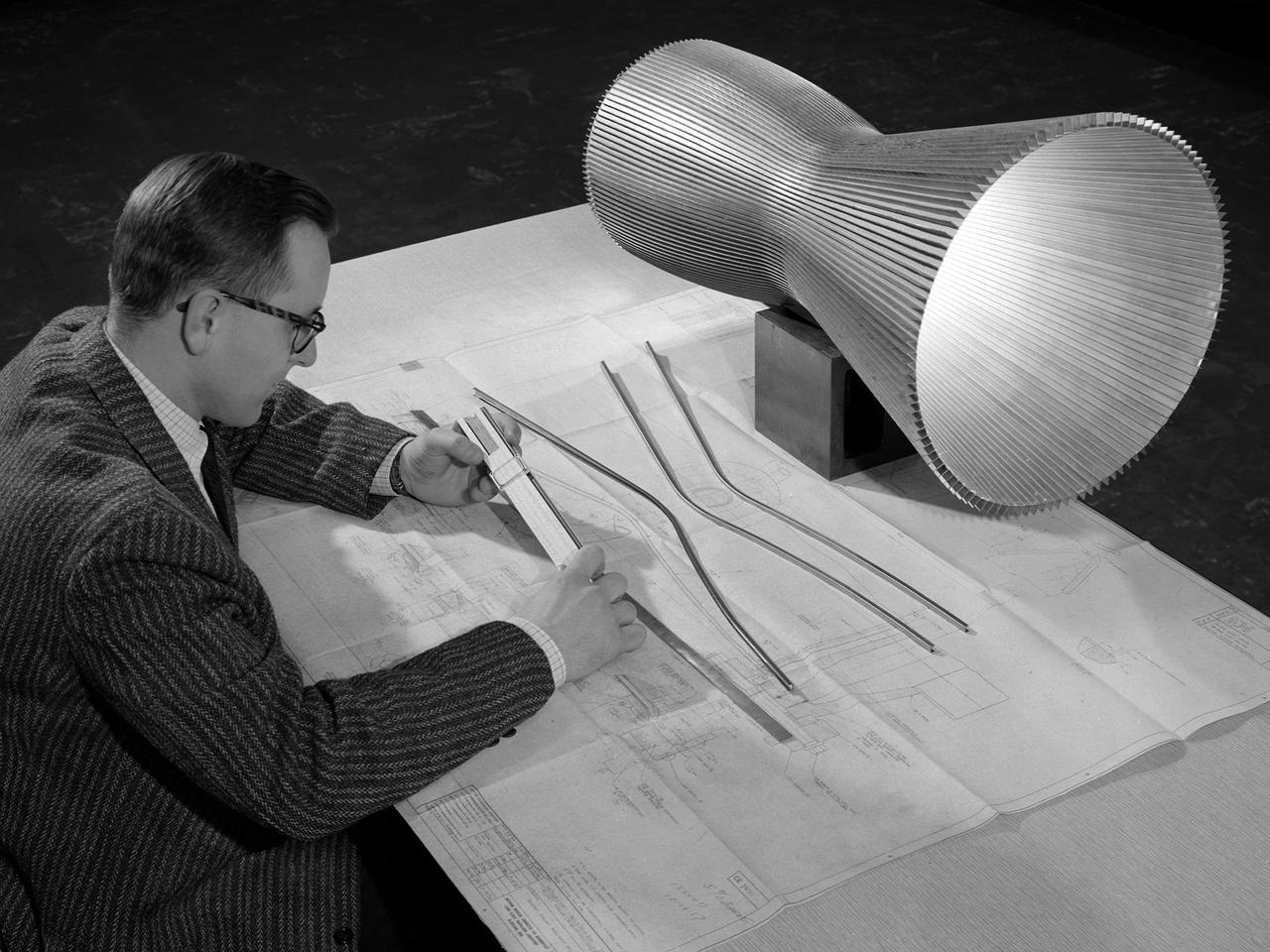
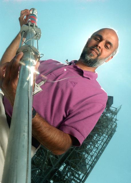
An engineer at the National Aeronautics and Space Administration (NASA) Lewis Research Center examines a drawing showing the assembly and details of a 20,000-pound thrust regeneratively cooled rocket engine. The engine was being designed for testing in Lewis’ new Rocket Engine Test Facility, which began operating in the fall of 1957. The facility was the largest high-energy test facility in the country that was capable of handling liquid hydrogen and other liquid chemical fuels. The facility’s use of subscale engines up to 20,000 pounds of thrust permitted a cost-effective method of testing engines under various conditions. The Rocket Engine Test Facility was critical to the development of the technology that led to the use of hydrogen as a rocket fuel and the development of lightweight, regeneratively-cooled, hydrogen-fueled rocket engines. Regeneratively-cooled engines use the cryogenic liquid hydrogen as both the propellant and the coolant to prevent the engine from burning up. The fuel was fed through rows of narrow tubes that surrounded the combustion chamber and nozzle before being ignited inside the combustion chamber. The tubes are visible in the liner sitting on the desk. At the time, Pratt and Whitney was designing a 20,000-pound thrust liquid-hydrogen rocket engine, the RL-10. Two RL-10s would be used to power the Centaur second-stage rocket in the 1960s. The successful development of the Centaur rocket and the upper stages of the Saturn V were largely credited to the work carried out Lewis.
ISS036-E-019885 (16 July 2013) --- NASA astronaut Chris Cassidy, Expedition 36 flight engineer, attired in an Extravehicular Mobility Unit (EMU) spacesuit, is pictured in the International Space Station’s Quest airlock as the July 16 spacewalk draws to a close. A little more than one hour into the spacewalk, European Space Agency astronaut Luca Parmitano (out of frame) reported water floating behind his head inside his helmet. The water was not an immediate health hazard for Parmitano, but Mission Control decided to end the spacewalk early.
The dart and associated launching system was developed by engineers at MSFC to collect a sample of the aluminum oxide particles during the static fire testing of the Shuttle's solid rocket motor. The dart is launched through the exhaust and recovered post test. The particles are collected on sticky copper tapes affixed to a cylindrical shaft in the dart. A protective sleeve draws over the tape after the sample is collected to prevent contamination. The sample is analyzed under a scarning electron microscope under high magnification and a particle size distribution is determined. This size distribution is input into the analytical model to predict the radiative heating rates from the motor exhaust. Good prediction models are essential to optimizing the development of the thermal protection system for the Shuttle.
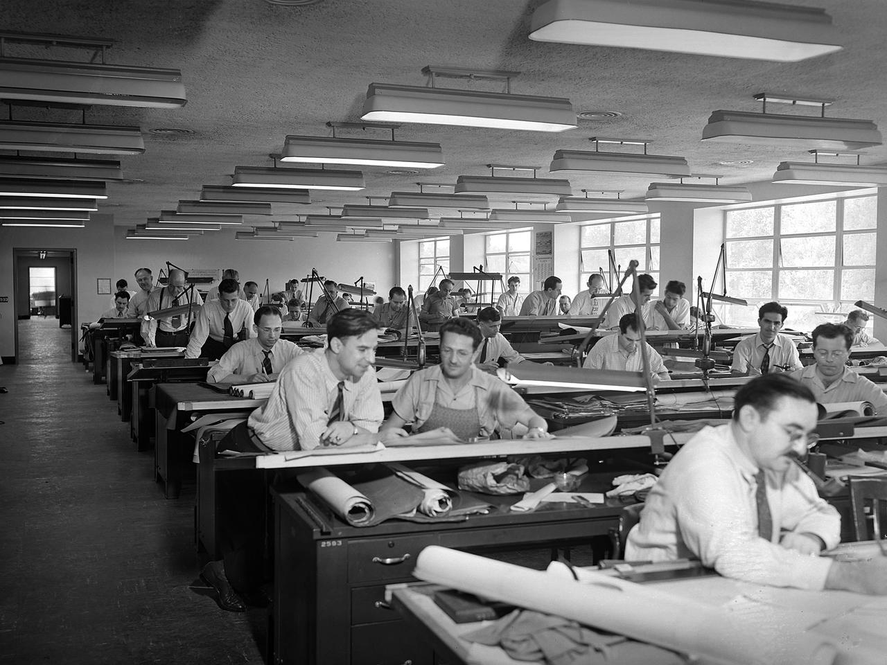
The National Advisory Committee for Aeronautics (NACA) Aircraft Engine Research Laboratory was designed by a group of engineers at the Langley Memorial Aeronautical Laboratory in late 1940 and 1941. Under the guidance of Ernest Whitney, the men worked on drawings and calculations in a room above Langley’s Structural Research Laboratory. The main Aircraft Engine Research Laboratory design group originally consisted of approximately 30 engineers and draftsmen, but there were smaller groups working separately on specific facilities. The new engine lab would have six principal buildings: the Engine Research Building, hangar, Fuels and Lubricants Building, Administration Building, Propeller Test Stand, and Altitude Wind Tunnel. In December 1941 most of those working on the project transferred to Cleveland from Langley. Harrison Underwood and Charles Egan led 18 architectural, 26 machine equipment, 3 structural and 10 mechanical draftsmen. Initially these staff members were housed in temporary offices in the hangar. As sections of the four-acre Engine Research Building were completed in the summer of 1942, the design team began relocating there. The Engine Research Building contained a variety of test cells and laboratories to address virtually every aspect of piston engine research. It also contained a two-story office wing, seen in this photograph that would later house many of the powerplant research engineers.
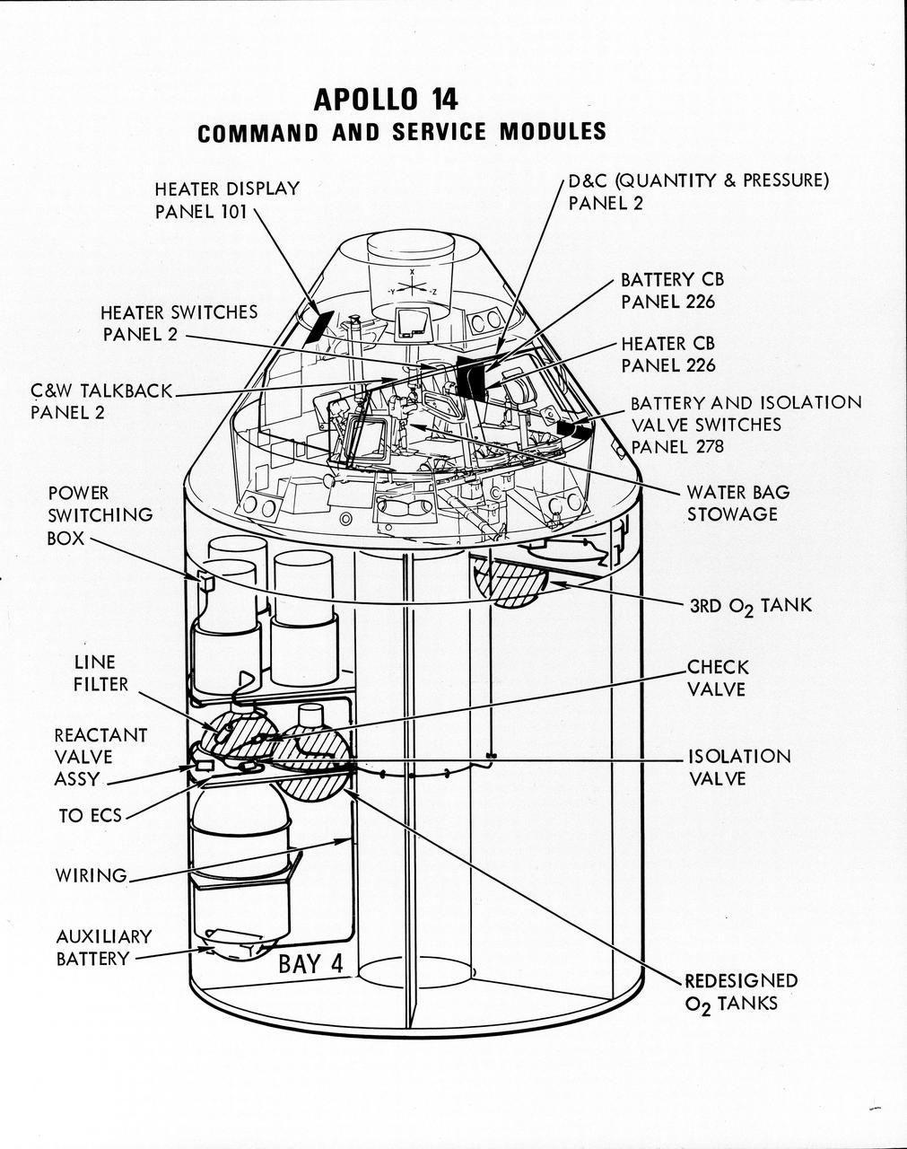
S71-16823 (January 1971) --- A line drawing illustrating a cutaway view of the Apollo 14 Command and Service Modules, showing the engineering changes in the CSM which were recommended by the Apollo 13 Review Board. (The Apollo 13 abort was caused by a short circuit and wiring overheating in one of the SM cryogenic oxygen tanks.) The major changes to the Apollo 14 CSM include adding a third cryogenic oxygen tank installed in a heretofore empty bay (in sector one) of the SM, addition of an auxiliary battery in the SM as a backup in case of fuel cell failure, and removal of destratification fans in the cryogenic oxygen tanks and removal of thermostat switches from the oxygen tank heater circuits. Provision for stowage of an emergency five-gallon supply of drinking water has been added to the CM.
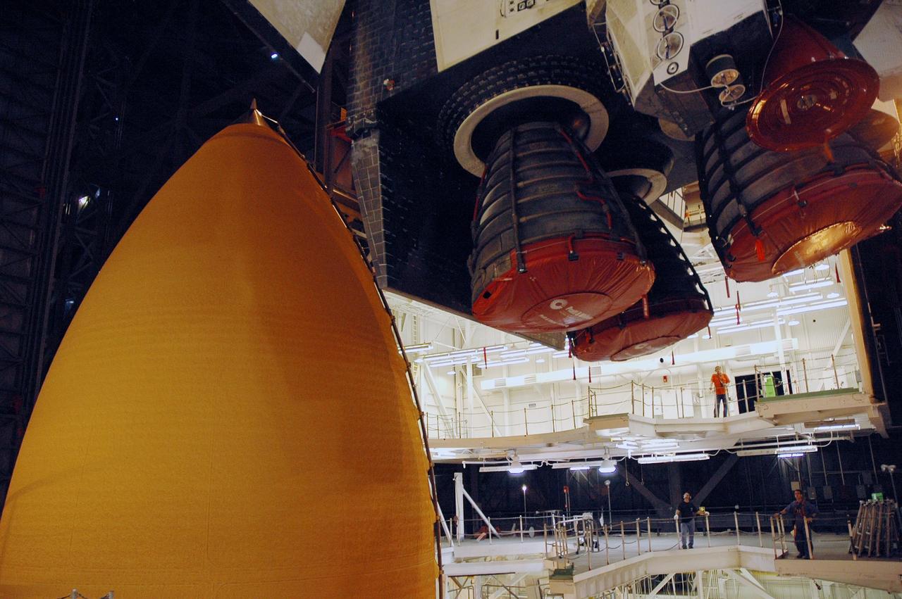
KENNEDY SPACE CENTER, FLA. -- The main engines on the orbiter Endeavour (upper right) are seen as Endeavour is lowered into high bay 1 of the Vehicle Assembly Building for stacking with the external tank (seen at left) and solid rocket boosters on the mobile launcher platform. Endeavour will be launched on mission STS-118, its first flight in more than four years. The shuttle has undergone extensive modifications, including the addition of safety upgrades already added to shuttles Discovery and Atlantis. Endeavour also features new hardware, such as the Station-to-Shuttle Power Transfer System that will allow the docked shuttle to draw electrical power from the station and extend its visits to the orbiting lab. Endeavour is targeted for launch on Aug. 7. Photo credit: NASA/Troy Cryder
![“I came [to the United States] in ’83 and in ’98, I was invited to go back to Costa Rica. The first Hispanic astronaut that NASA ever had is a Costa Rican — Franklin Chang Diaz. So everyone was talking about Franklin. At that point I had been working for NASA for seven years. All of a sudden, I had little girls and women coming to me, wanting to ask me about engineering. I resisted it at first, because I thought, they only care about the astronauts. That’s what ran through my head at first. I didn’t think I had done anything at that point. I didn’t think that I could be a role model. But as time went on, people started to hear about me more in Costa Rica, and eventually throughout Latin America. I got requests to travel all over to give talks — all the way from Mexico down to Chile. I cannot tell you when it was, but I realized, there are so many men in this field. When a little kid draws an engineer or a scientist, they tend to draw men. But here I am. And maybe I haven’t accomplished everything I want to do. But I can show little girls and little boys out there that it doesn’t matter where you come from. You can be anything that you want to, even when you have had a very difficult upbringing.” Earth Science Deputy Division Director in the Science Mission Directorate, Sandra Cauffman, poses for a portrait, Friday, Sept. 17, 2021 at NASA Headquarters in Washington. Photo Credit: (NASA/Aubrey Gemignani)](https://images-assets.nasa.gov/image/NHQ202109170001/NHQ202109170001~medium.jpg)
“I came [to the United States] in ’83 and in ’98, I was invited to go back to Costa Rica. The first Hispanic astronaut that NASA ever had is a Costa Rican — Franklin Chang Diaz. So everyone was talking about Franklin. At that point I had been working for NASA for seven years. All of a sudden, I had little girls and women coming to me, wanting to ask me about engineering. I resisted it at first, because I thought, they only care about the astronauts. That’s what ran through my head at first. I didn’t think I had done anything at that point. I didn’t think that I could be a role model. But as time went on, people started to hear about me more in Costa Rica, and eventually throughout Latin America. I got requests to travel all over to give talks — all the way from Mexico down to Chile. I cannot tell you when it was, but I realized, there are so many men in this field. When a little kid draws an engineer or a scientist, they tend to draw men. But here I am. And maybe I haven’t accomplished everything I want to do. But I can show little girls and little boys out there that it doesn’t matter where you come from. You can be anything that you want to, even when you have had a very difficult upbringing.” Earth Science Deputy Division Director in the Science Mission Directorate, Sandra Cauffman, poses for a portrait, Friday, Sept. 17, 2021 at NASA Headquarters in Washington. Photo Credit: (NASA/Aubrey Gemignani)
KENNEDY SPACE CENTER, FLA. -- Quality inspectors with NASA and Lockheed Martin examine a red-line drawing of foam placement on space shuttle Atlantis's external tank (in front of them) to verify the foam insulation that was reapplied. The foam covers the feed-through engine cut-off, or ECO, sensor connector. The foam was removed to enable engineers to remove and replace the ECO sensor connector on the tank. The feed-through connector passes the wires from the inside of the tank to the outside. Results of a tanking test on Dec. 18 pointed to an open circuit in the feed-through connector wiring, which is located at the base of the tank. The pins in the replacement connector were precisely soldered to create a connection that allows sensors inside the tank to send signals to the computers onboard Atlantis. The repair work was done on Atlantis while the shuttle has been on Launch Pad 39A at NASA's Kennedy Space Center. The launch date for the shuttle's STS-122 mission has now been targeted for Feb. 7. Photo credit: NASA/Cory Husten
KENNEDY SPACE CENTER, FLA. -- Quality inspectors with NASA and Lockheed Martin examine a red-line drawing of foam placement on space shuttle Atlantis's external tank (in front of them) to verify the foam insulation that was reapplied. The foam covers the feed-through engine cut-off, or ECO, sensor connector. The foam was removed to enable engineers to remove and replace the ECO sensor connector on the tank. The feed-through connector passes the wires from the inside of the tank to the outside. Results of a tanking test on Dec. 18 pointed to an open circuit in the feed-through connector wiring, which is located at the base of the tank. The pins in the replacement connector were precisely soldered to create a connection that allows sensors inside the tank to send signals to the computers onboard Atlantis. The repair work was done on Atlantis while the shuttle has been on Launch Pad 39A at NASA's Kennedy Space Center. The launch date for the shuttle's STS-122 mission has now been targeted for Feb. 7. Photo credit: NASA/Cory Husten
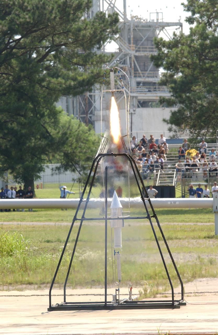
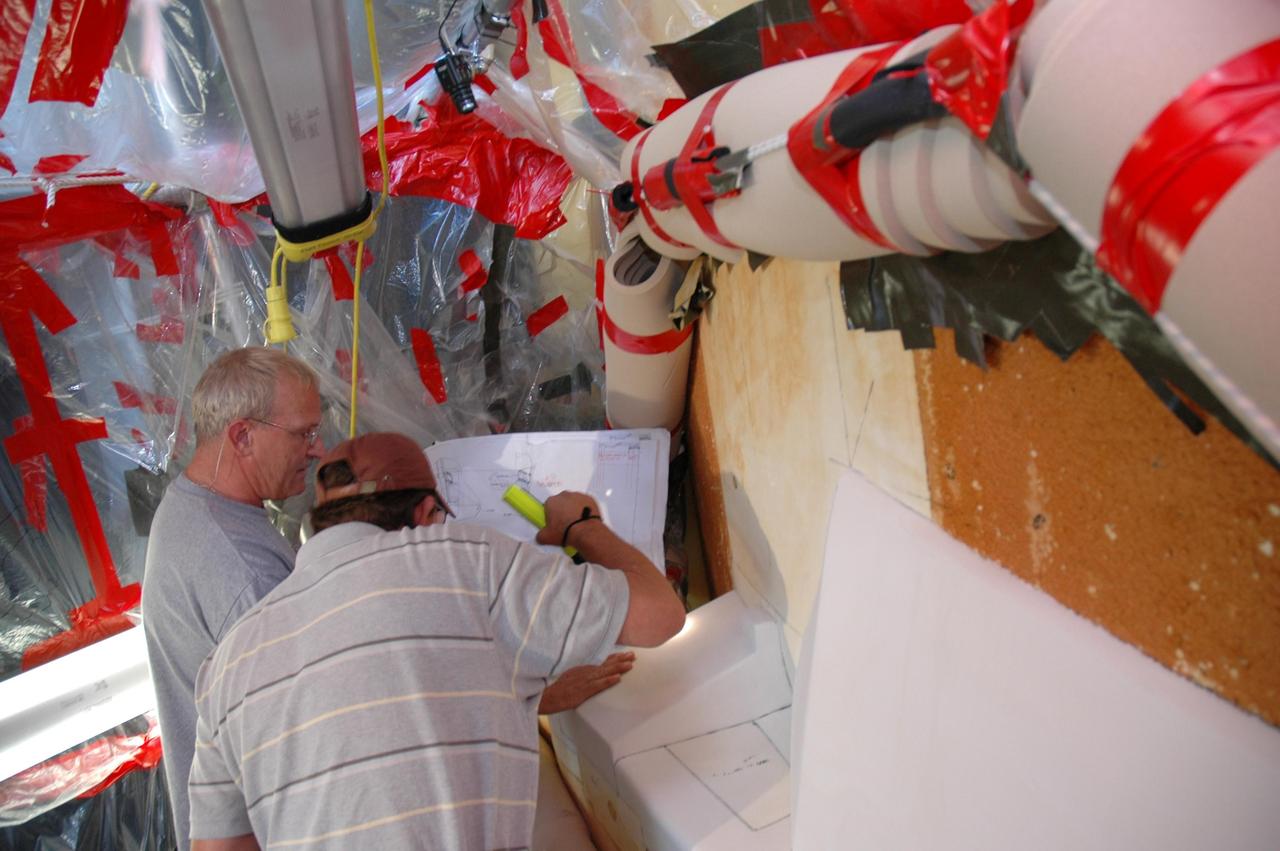
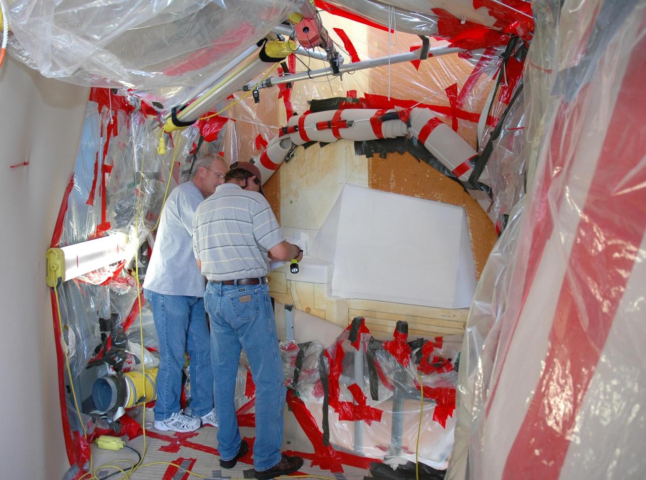
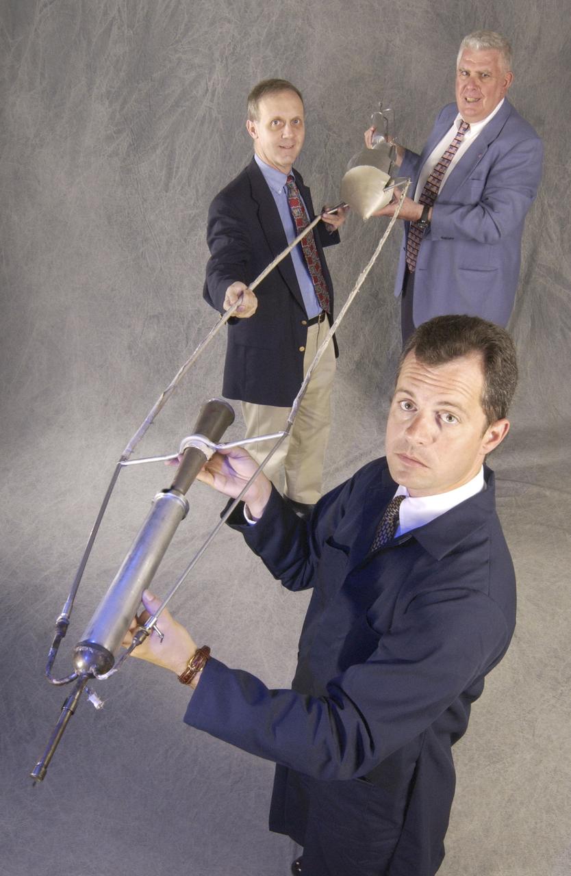
In honor of the Centernial of Flight Celebration and commissioned by the American Institute of Aeronautics and Astronautics (AIAA), a team of engineers from Marshall Space Flight Center (MSFC) built a replica of the first liquid-fueled rocket. The original rocket, designed and built by rocket engineering pioneer Robert H. Goddard in 1926, opened the door to modern rocketry. Goddard's rocket reached an altitude of 41 feet while its flight lasted only 2.5 seconds. The Marshall design team's plan was to stay as close as possible to an authentic reconstruction of Goddard's rocket. The same propellants were used - liquid oxygen and gasoline - as available during Goddard's initial testing and firing. The team also tried to construct the replica using the original materials and design to the greatest extent possible. By purposely using less advanced techniques and materials than many that are available today, the team encountered numerous technical challenges in testing the functional hardware. There were no original blueprints or drawings, only photographs and notes. However, this faithful adherence to historical accuracy has allowed the team to experience many of the same challenges Goddard faced 77 years ago, and more fully appreciate the genius of this extraordinary man. In this photo, the replica is shown firing in the A-frame launch stand in near-flight configuration at MSFC's Test Area 116 during the American Institute of Aeronautics and Astronautics 39th Joint Propulsion Conference on July 23, 2003.
In honor of the Centernial of Flight celebration and commissioned by the American Institute of Aeronautics and Astronautics (AIAA), a team of engineers from Marshall Space Flight Center (MSFC) built a replica of the first liquid-fueled rocket. The original rocket, designed and built by rocket engineering pioneer Robert H. Goddard in 1926, opened the door to modern rocketry. Goddard's rocket reached an altitude of 41 feet while its flight lasted only 2.5 seconds. The Marshall design team's plan was to stay as close as possible to an authentic reconstruction of Goddard's rocket. The same propellants were used - liquid oxygen and gasoline - as available during Goddard's initial testing and firing. The team also tried to construct the replica using the original materials and design to the greatest extent possible. By purposely using less advanced techniques and materials than many that are available today, the team encountered numerous technical challenges in testing the functional hardware. There were no original blueprints or drawings, only photographs and notes. However, this faithful adherence to historical accuracy has also allowed the team to experience many of the same challenges Goddard faced 77 years ago, and more fully appreciate the genius of this extraordinary man. The replica will undergo ground tests at MSFC this summer.
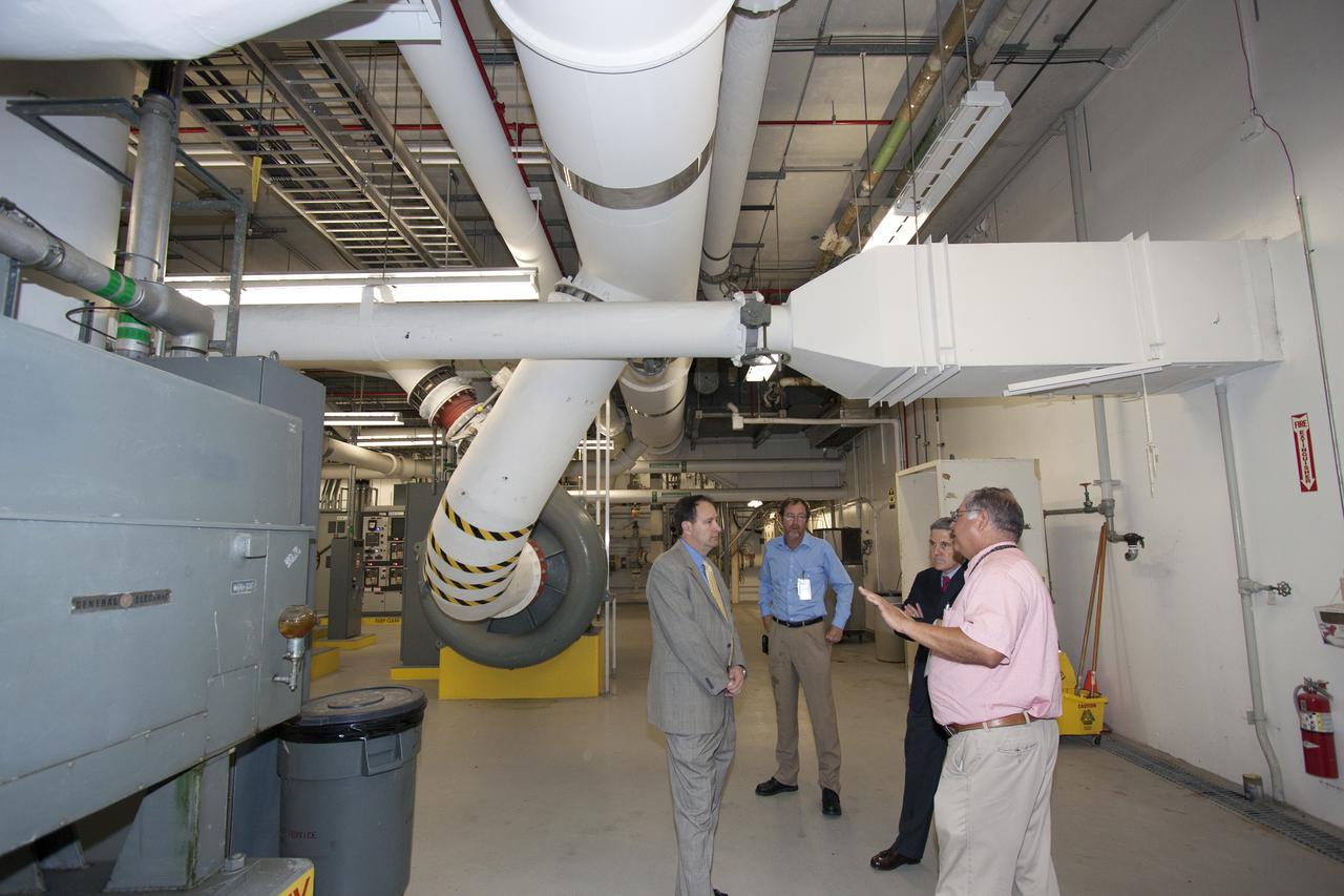
CAPE CANAVERAL, Fla. – NASA Associate Administrator Robert Lightfoot tours the Environmental Control System Room under the surface of Launch Pad 39B during a visit to NASA's Kennedy Space Center in Florida. From left are Lightfoot, Alan Littlefield, Vehicle Integration and Launch chief engineer, Kennedy Director Bob Cabana, and Jose Perez Morales, launch pad project manager. The pad is being modified to support NASA's new Orion spacecraft and Space Launch System heavy-lift rocket, the SLS. NASA's FY2014 budget proposal includes a plan to robotically capture a small near-Earth asteroid and redirect it safely to a stable orbit in the Earth-moon system where astronauts can visit and explore it. Performing these elements for the proposed asteroid initiative integrates the best of NASA's science, technology and human exploration capabilities and draws on the innovation of America's brightest scientists and engineers. It uses current and developing capabilities to find both large asteroids that pose a hazard to Earth and small asteroids that could be candidates for the initiative, accelerates our technology development activities in high-powered solar electric propulsion and takes advantage of our hard work on the Space Launch System rocket and Orion spacecraft, helping to keep NASA on target to reach the President's goal of sending humans to Mars in the 2030s. Photo credit: NASA_Jim Grossmann

CAPE CANAVERAL, Fla. – NASA Associate Administrator Robert Lightfoot tours Launch Pad 39B during a visit to NASA's Kennedy Space Center in Florida. From left are Alan Littlefield, Vehicle Integration and Launch chief engineer, Jose Perez Morales, launch pad project manager, Lightfoot, and Kennedy Director Bob Cabana. The pad is being modified to support NASA's new Orion spacecraft and Space Launch System heavy-lift rocket, the SLS. NASA's FY2014 budget proposal includes a plan to robotically capture a small near-Earth asteroid and redirect it safely to a stable orbit in the Earth-moon system where astronauts can visit and explore it. Performing these elements for the proposed asteroid initiative integrates the best of NASA's science, technology and human exploration capabilities and draws on the innovation of America's brightest scientists and engineers. It uses current and developing capabilities to find both large asteroids that pose a hazard to Earth and small asteroids that could be candidates for the initiative, accelerates our technology development activities in high-powered solar electric propulsion and takes advantage of our hard work on the Space Launch System rocket and Orion spacecraft, helping to keep NASA on target to reach the President's goal of sending humans to Mars in the 2030s. Photo credit: NASA_Jim Grossmann
KENNEDY SPACE CENTER, FLA. -- Quality inspectors with NASA and Lockheed Martin examine a red-line drawing of foam placement on space shuttle Atlantis's external tank (in front of them) to verify the foam insulation that was reapplied. The foam covers the feed-through engine cut-off, or ECO, sensor connector. The foam was removed to enable engineers to remove and replace the ECO sensor connector on the tank. The feed-through connector passes the wires from the inside of the tank to the outside. Results of a tanking test on Dec. 18 pointed to an open circuit in the feed-through connector wiring, which is located at the base of the tank. The pins in the replacement connector were precisely soldered to create a connection that allows sensors inside the tank to send signals to the computers onboard Atlantis. The repair work was done on Atlantis while the shuttle has been on Launch Pad 39A at NASA's Kennedy Space Center. The launch date for the shuttle's STS-122 mission has now been targeted for Feb. 7. Photo credit: NASA/Cory Husten
KENNEDY SPACE CENTER, FLA. -- Quality inspectors with NASA and Lockheed Martin examine a red-line drawing of foam placement on space shuttle Atlantis's external tank (in front of them) to verify the foam insulation that was reapplied. The foam covers the feed-through engine cut-off, or ECO, sensor connector. The foam was removed to enable engineers to remove and replace the ECO sensor connector on the tank. The feed-through connector passes the wires from the inside of the tank to the outside. Results of a tanking test on Dec. 18 pointed to an open circuit in the feed-through connector wiring, which is located at the base of the tank. The pins in the replacement connector were precisely soldered to create a connection that allows sensors inside the tank to send signals to the computers onboard Atlantis. The repair work was done on Atlantis while the shuttle has been on Launch Pad 39A at NASA's Kennedy Space Center. The launch date for the shuttle's STS-122 mission has now been targeted for Feb. 7. Photo credit: NASA/Cory Husten
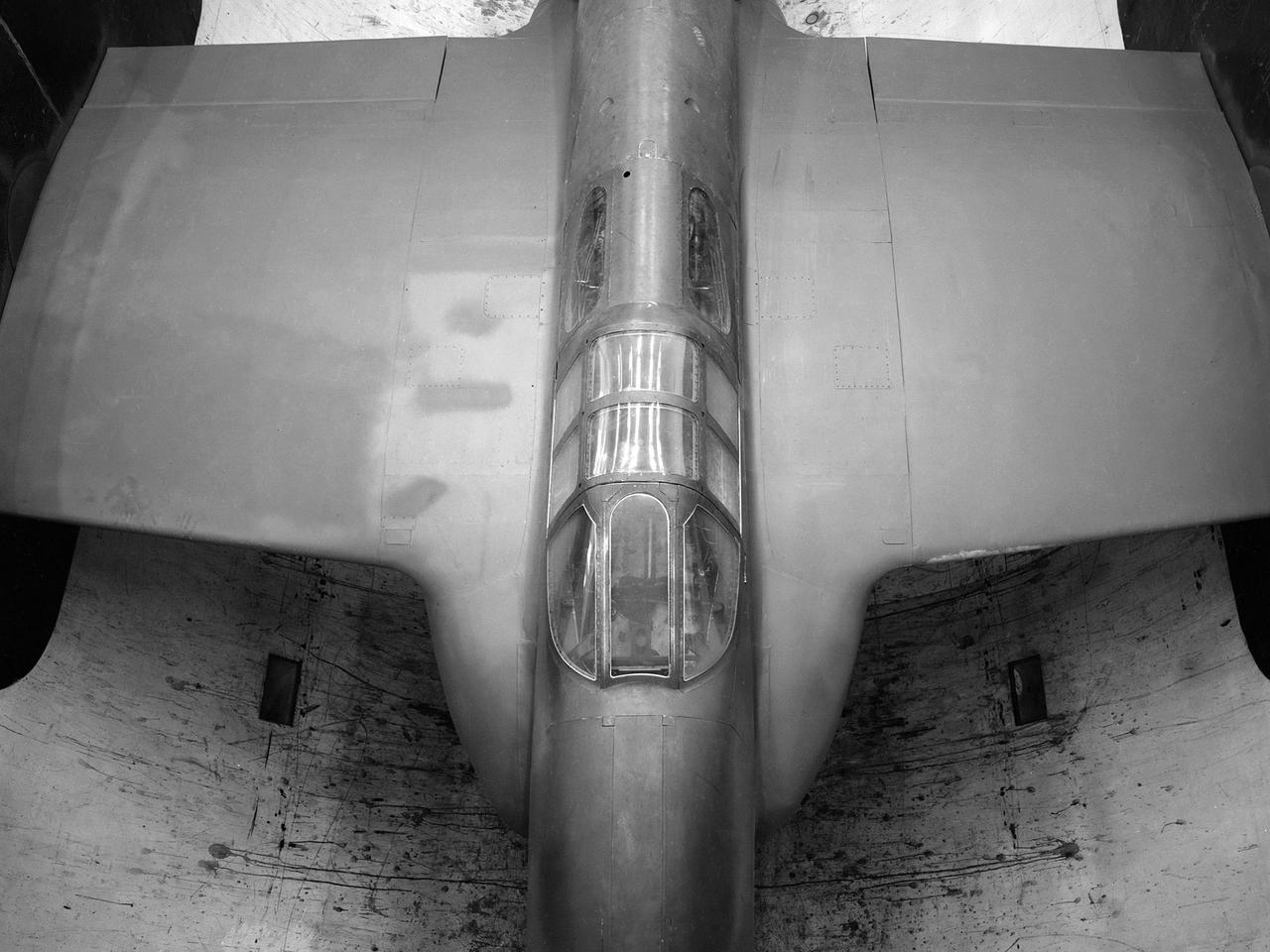
The secret test of the Bell YP–59A Airacomet in the spring of 1944 was the first investigation in the National Advisory Committee for Aeronautics (NACA) Aircraft Engine Research Laboratory’s new Altitude Wind Tunnel (AWT). The Airacomet, powered by two General Electric I–A centrifugal turbojets, was the first US jet aircraft. The Airacomet’s 290-miles per hour speed, however, was dwarfed by the German Messerschmitt Me-262 Schwalbe’s 540 miles per hour. In 1941 and 1942 General Electric built the first US jet engines based on technical drawings from British engineer Frank Whittle. Bell Aircraft was contracted to produce an airframe to incorporate the new engines. The result was the Bell XP–59A Airacomet. The aircraft made its first flight over Muroc Lake, California, on October 2, 1942. The aircraft continued to struggle over the next year and the NACA was asked to test it in the new AWT. A Bell YP–59A was flown from the Bell plant in Buffalo to Cleveland by Bob Stanley, who had piloted the first successful flight of the XP–59A at Muroc in 1942. The wing tips and tail were cut from the aircraft so that it would fit into the AWT’s test section. The study first analyzed the engines in their original configuration and then implemented a boundary layer removal duct, a new nacelle inlet, and new cooling seals. Tests of the modified version showed that the improved airflow distribution increased the I–16’s performance by 25 percent. Despite the improved speed, the aircraft was not stable enough to be used in combat, and the design was soon abandoned.
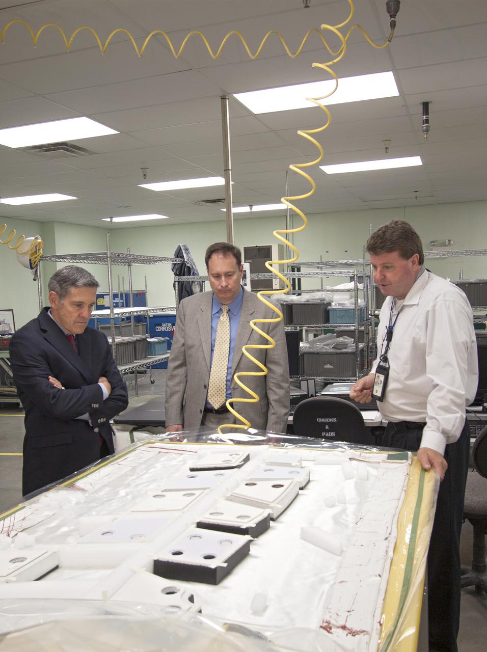
CAPE CANAVERAL, Fla. – NASA Associate Administrator Robert Lightfoot, center, tours the Thermal Protection System Facility, or TPSF, during a visit to NASA's Kennedy Space Center in Florida. From left are Kennedy Director Bob Cabana, Lightfoot, and Martin Boyd, TPSF manager with Jacobs Technologies, briefing his guests on the production of TPS tile for NASA's new Orion spacecraft. NASA's FY2014 budget proposal includes a plan to robotically capture a small near-Earth asteroid and redirect it safely to a stable orbit in the Earth-moon system where astronauts can visit and explore it. Performing these elements for the proposed asteroid initiative integrates the best of NASA's science, technology and human exploration capabilities and draws on the innovation of America's brightest scientists and engineers. It uses current and developing capabilities to find both large asteroids that pose a hazard to Earth and small asteroids that could be candidates for the initiative, accelerates our technology development activities in high-powered solar electric propulsion and takes advantage of our hard work on the Space Launch System rocket and Orion spacecraft, helping to keep NASA on target to reach the President's goal of sending humans to Mars in the 2030s. Photo credit: NASA_Jim Grossmann
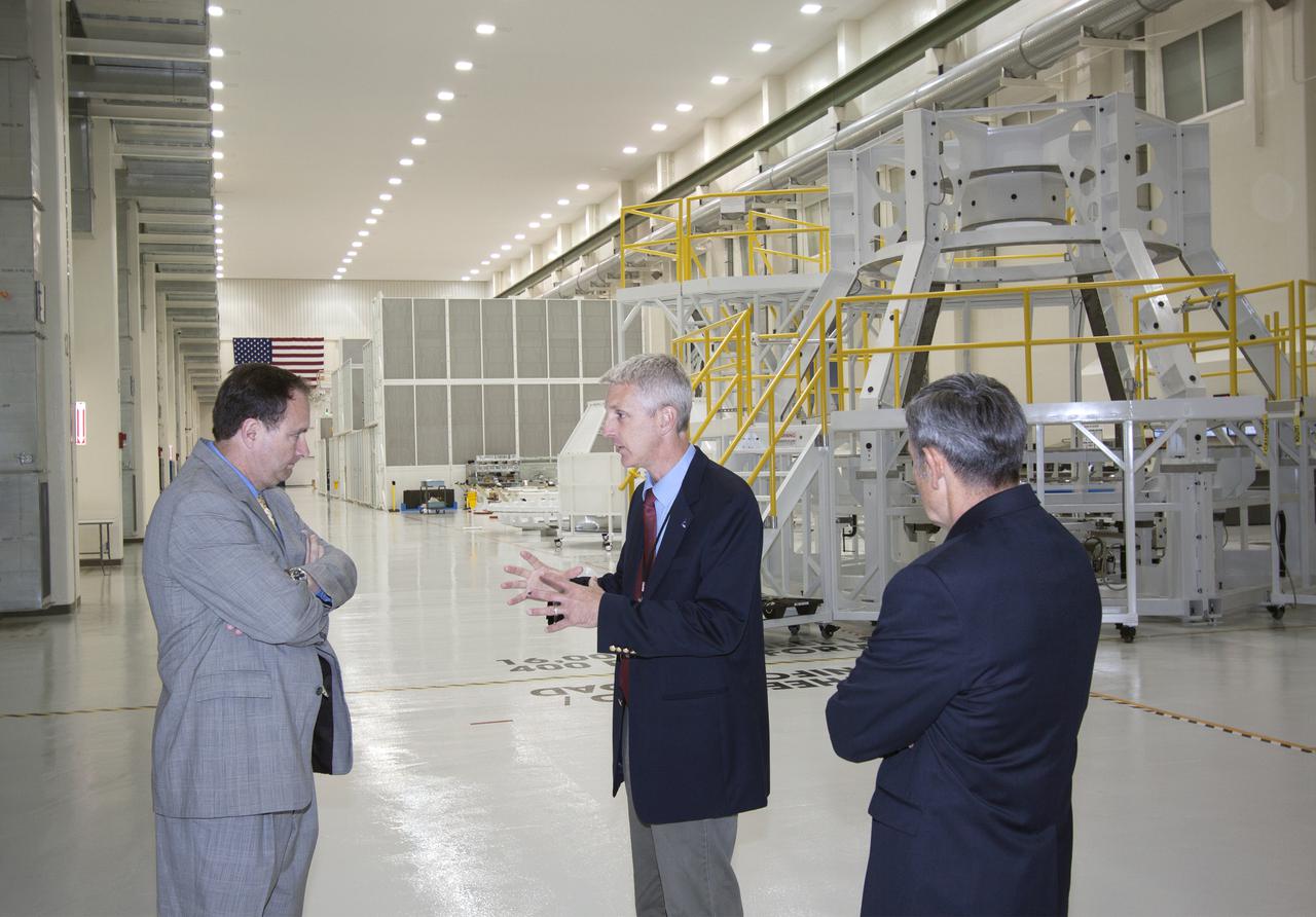
CAPE CANAVERAL, Fla. – During a visit to NASA's Kennedy Space Center in Florida, NASA Associate Administrator Robert Lightfoot tours the Operations and Checkout Building high bay where the first Orion capsule, NASA's multi-purpose crew vehicle, is being prepared for flight on Exploration Flight Test 1, or EFT-1, in 2014. From left are Lightfoot, Kennedy's manager of Orion Production Operations Scott Wilson, and Kennedy Director Bob Cabana. Orion is NASA's next-generation transport for astronauts to destinations beyond Earth orbit. NASA's FY2014 budget proposal includes a plan to robotically capture a small near-Earth asteroid and redirect it safely to a stable orbit in the Earth-moon system where astronauts can visit and explore it. Performing these elements for the proposed asteroid initiative integrates the best of NASA's science, technology and human exploration capabilities and draws on the innovation of America's brightest scientists and engineers. It uses current and developing capabilities to find both large asteroids that pose a hazard to Earth and small asteroids that could be candidates for the initiative, accelerates our technology development activities in high-powered solar electric propulsion and takes advantage of our hard work on the Space Launch System rocket and Orion spacecraft, helping to keep NASA on target to reach the President's goal of sending humans to Mars in the 2030s. Photo credit: NASA_Jim Grossmann
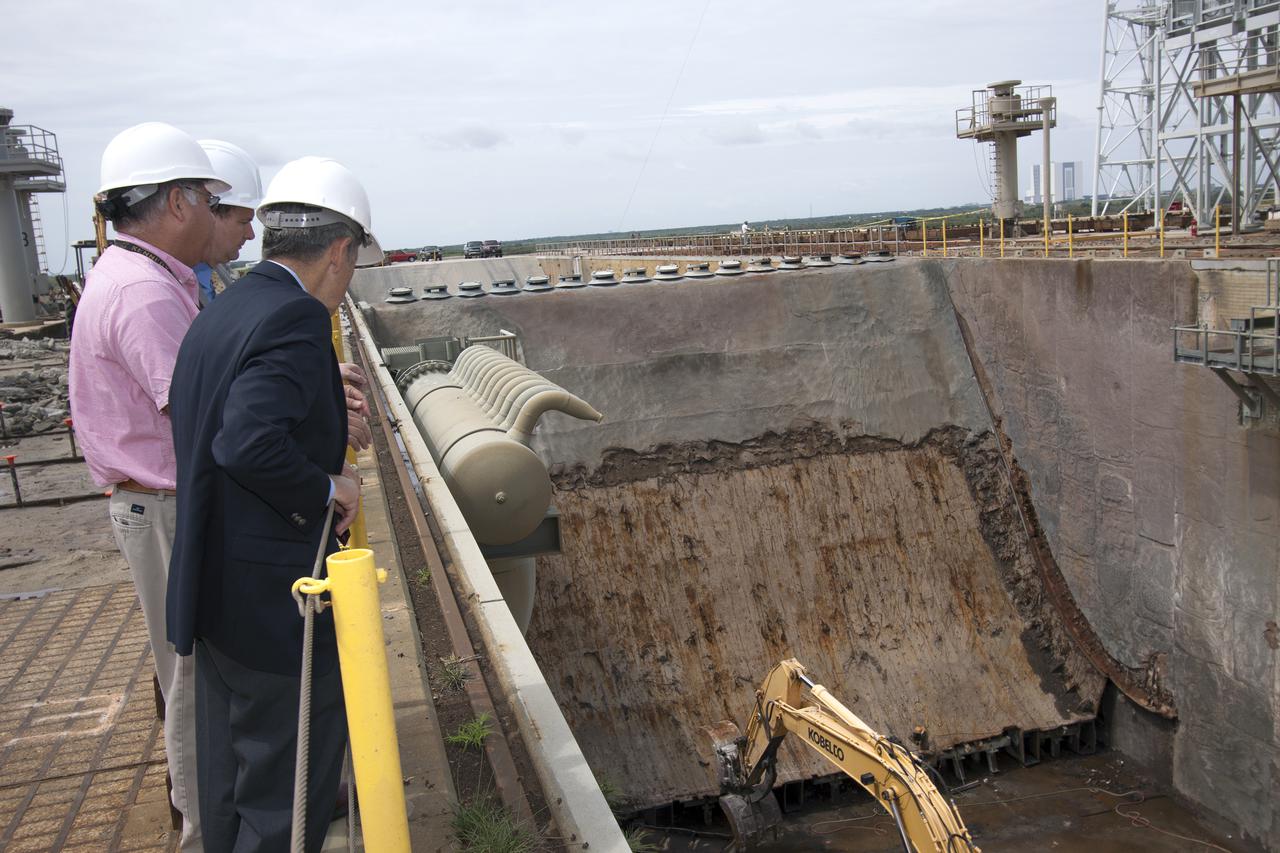
CAPE CANAVERAL, Fla. – NASA Associate Administrator Robert Lightfoot gets a close look at the flame deflector on Launch Pad 39B during a visit to NASA's Kennedy Space Center in Florida. From left are Lightfoot, Jose Perez Morales, launch pad project manager, and Kennedy Director Bob Cabana. The pad is being modified to support NASA's new Orion spacecraft and Space Launch System heavy-lift rocket, the SLS. NASA's FY2014 budget proposal includes a plan to robotically capture a small near-Earth asteroid and redirect it safely to a stable orbit in the Earth-moon system where astronauts can visit and explore it. Performing these elements for the proposed asteroid initiative integrates the best of NASA's science, technology and human exploration capabilities and draws on the innovation of America's brightest scientists and engineers. It uses current and developing capabilities to find both large asteroids that pose a hazard to Earth and small asteroids that could be candidates for the initiative, accelerates our technology development activities in high-powered solar electric propulsion and takes advantage of our hard work on the Space Launch System rocket and Orion spacecraft, helping to keep NASA on target to reach the President's goal of sending humans to Mars in the 2030s. Photo credit: NASA_Jim Grossmann
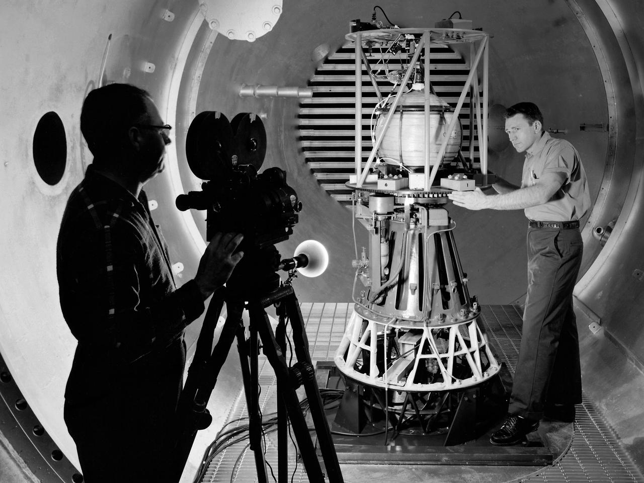
Mechanic Howard Wine inspects the setup of a spin isolator in Cell 2 of the Propulsion Systems Laboratory at the National Aeronautics and Space Administration (NASA) Lewis Research Center. Photographer Al Jecko filmed the proceedings. This test was unique in that the chamber’s altitude system was used, but not its inlet air flow. The test was in preparation for an upcoming launch of modified liquid hydrogen propellant tank on a sounding rocket. This Weightlessness Analysis Sounding Probe (WASP) was part of Lewis investigation into methods for controlling partially filled liquid hydrogen fuel tanks during flight. Second-stage rockets, the Centaur in particular, were designed to stop their engines and coast, then restart them when needed. During this coast period, the propellant often shifted inside the tank. This movement could throw the rocket off course or result in the sloshing of fuel away from the fuel pump. Wine was one of only three journeymen mechanics at Lewis when he was hired in January 1954. He spent his first decade in the Propulsion Systems Laboratory and was soon named a section head. Wine went on to serve as Assistant Division Chief and later served as an assistant to the director. Jecko joined the center in 1947 as a photographer and artist. He studied at the Cleveland School or Art and was known for his cartoon drawing. He worked at the center for 26 years.
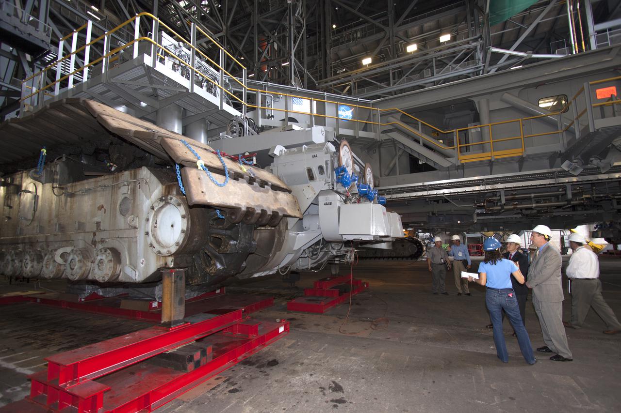
CAPE CANAVERAL, Fla. – NASA Associate Administrator Robert Lightfoot, second from right, is briefed on the modifications to crawler-transporter 2 in the Vehicle Assembly Building, or VAB, during a visit to NASA's Kennedy Space Center in Florida. From left are Mary Hanna, crawler-transporter project manager, Kennedy Director Bob Cabana, Lightfoot, and Shawn Quinn, Vehicle Integration and Launch Integration Product Team, or IPT, manager. Crawler-transporter 2 is being readied to support NASA's new Orion spacecraft and Space Launch System heavy-lift rocket, the SLS. NASA's FY2014 budget proposal includes a plan to robotically capture a small near-Earth asteroid and redirect it safely to a stable orbit in the Earth-moon system where astronauts can visit and explore it. Performing these elements for the proposed asteroid initiative integrates the best of NASA's science, technology and human exploration capabilities and draws on the innovation of America's brightest scientists and engineers. It uses current and developing capabilities to find both large asteroids that pose a hazard to Earth and small asteroids that could be candidates for the initiative, accelerates our technology development activities in high-powered solar electric propulsion and takes advantage of our hard work on the Space Launch System rocket and Orion spacecraft, helping to keep NASA on target to reach the President's goal of sending humans to Mars in the 2030s. Photo credit: NASA_Jim Grossmann
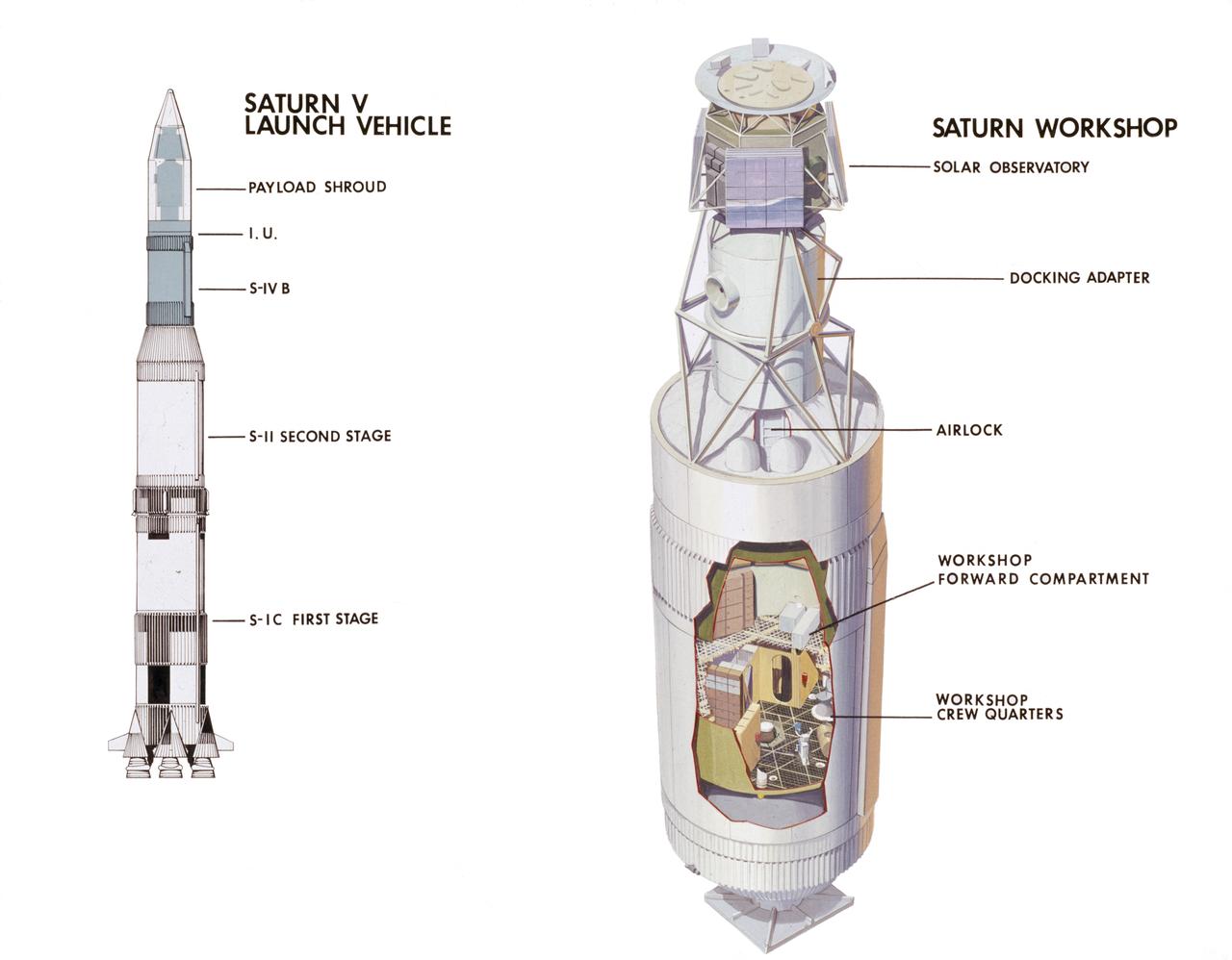
This cutaway drawing illustrates major Skylab components in launch configuration on top of the Saturn V. In an early effort to extend the use of Apollo for further applications, NASA established the Apollo Applications Program (AAP) in August of 1965. The AAP was to include long duration Earth orbital missions during which astronauts would carry out scientific, technological, and engineering experiments in space by utilizing modified Saturn launch vehicles and the Apollo spacecraft. Established in 1970, the Skylab Program was the forerurner of the AAP. The goals of the Skylab were to enrich our scientific knowledge of the Earth, the Sun, the stars, and cosmic space; to study the effects of weightlessness on living organisms, including man; to study the effects of the processing and manufacturing of materials utilizing the absence of gravity; and to conduct Earth resource observations. The Skylab also conducted 19 selected experiments submitted by high school students. Skylab's 3 different 3-man crews spent up to 84 days in Earth orbit. The Marshall Space Flight Center (MSFC) had responsibility for developing and integrating most of the major components of the Skylab: the Orbital Workshop (OWS), Airlock Module (AM), Multiple Docking Adapter (MDA), Apollo Telescope Mount (ATM), Payload Shroud (PS), and most of the experiments. MSFC was also responsible for providing the Saturn IB launch vehicles for three Apollo spacecraft and crews and a Saturn V launch vehicle for the Skylab.
CAPE CANAVERAL, Fla. – NASA Associate Administrator Robert Lightfoot, center, tours the Vehicle Assembly Building, or VAB, during a visit to NASA's Kennedy Space Center in Florida. Here, he receives a briefing from Mary Hanna, crawler-transporter project manager. Behind him, from left, are Kennedy Space Center Director Bob Cabana, Jose Lopez, VAB project manager, and Joy Burkey, program specialist. The VAB is being readied to support NASA's new Orion spacecraft and Space Launch System heavy-lift rocket, the SLS. NASA's FY2014 budget proposal includes a plan to robotically capture a small near-Earth asteroid and redirect it safely to a stable orbit in the Earth-moon system where astronauts can visit and explore it. Performing these elements for the proposed asteroid initiative integrates the best of NASA's science, technology and human exploration capabilities and draws on the innovation of America's brightest scientists and engineers. It uses current and developing capabilities to find both large asteroids that pose a hazard to Earth and small asteroids that could be candidates for the initiative, accelerates our technology development activities in high-powered solar electric propulsion and takes advantage of our hard work on the Space Launch System rocket and Orion spacecraft, helping to keep NASA on target to reach the President's goal of sending humans to Mars in the 2030s. Photo credit: NASA_Jim Grossmann
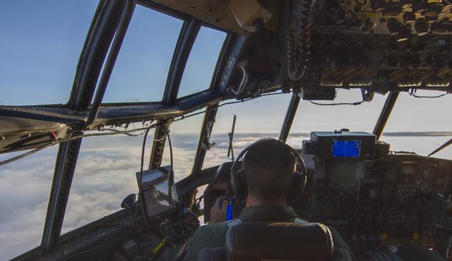
The immense glass windshield on the C130 affords a panoramic view of the world. This plane typically flies with a pilot, copilot and flight engineer on the flight deck, as well as an air crewman in the main cabin. --- The <b><a href="http://naames.larc.nasa.gov/" rel="nofollow">North Atlantic Aerosols and Marine Ecosystems Study </a></b> (NAAMES) is a five year investigation to resolve key processes controlling ocean system function, their influences on atmospheric aerosols and clouds and their implications for climate. Michael Starobin joined the NAAMES field campaign on behalf of Earth Expeditions and NASA Goddard Space Flight Center’s Office of Communications. He presented stories about the important, multi-disciplinary research being conducted by the NAAMES team, with an eye towards future missions on the NASA drawing board. This is a NAAMES photo essay put together by Starobin, a collection of 49 photographs and captions. Photo and Caption Credit: Michael Starobin <b><a href="http://www.nasa.gov/audience/formedia/features/MP_Photo_Guidelines.html" rel="nofollow">NASA image use policy</a></b> <b><a href="http://www.nasa.gov/centers/goddard/home/index.html" rel="nofollow">NASA Goddard Space Flight Center</a></b> enables NASA’s mission through four scientific endeavors: Earth Science, Heliophysics, Solar System Exploration, and Astrophysics. Goddard plays a leading role in NASA’s accomplishments by contributing compelling scientific knowledge to advance the Agency’s mission. <b>Follow us on <a href="http://twitter.com/NASAGoddardPix" rel="nofollow">Twitter</a></b> <b>Like us on <a href="http://www.facebook.com/pages/Greenbelt-MD/NASA-Goddard/395013845897?ref=tsd" rel="nofollow">Facebook</a></b> <b>Find us on <a href="https://www.instagram.com/nasagoddard/?hl=en" rel="nofollow">Instagram</a></b>
Scientists and engineers regularly tweaked and tested specialized equipment attached to the C130. Here two of the NAAMES team are inspecting a cloud probe that typically hangs on the wingtip of the plane. --- The <b><a href="http://naames.larc.nasa.gov/" rel="nofollow">North Atlantic Aerosols and Marine Ecosystems Study </a></b> (NAAMES) is a five year investigation to resolve key processes controlling ocean system function, their influences on atmospheric aerosols and clouds and their implications for climate. Michael Starobin joined the NAAMES field campaign on behalf of Earth Expeditions and NASA Goddard Space Flight Center’s Office of Communications. He presented stories about the important, multi-disciplinary research being conducted by the NAAMES team, with an eye towards future missions on the NASA drawing board. This is a NAAMES photo essay put together by Starobin, a collection of 49 photographs and captions. Photo and Caption Credit: Michael Starobin <b><a href="http://www.nasa.gov/audience/formedia/features/MP_Photo_Guidelines.html" rel="nofollow">NASA image use policy</a></b> <b><a href="http://www.nasa.gov/centers/goddard/home/index.html" rel="nofollow">NASA Goddard Space Flight Center</a></b> enables NASA’s mission through four scientific endeavors: Earth Science, Heliophysics, Solar System Exploration, and Astrophysics. Goddard plays a leading role in NASA’s accomplishments by contributing compelling scientific knowledge to advance the Agency’s mission. <b>Follow us on <a href="http://twitter.com/NASAGoddardPix" rel="nofollow">Twitter</a></b> <b>Like us on <a href="http://www.facebook.com/pages/Greenbelt-MD/NASA-Goddard/395013845897?ref=tsd" rel="nofollow">Facebook</a></b> <b>Find us on <a href="https://www.instagram.com/nasagoddard/?hl=en" rel="nofollow">Instagram</a></b>

CAPE CANAVERAL, Fla. – During a visit to NASA's Kennedy Space Center in Florida, NASA Associate Administrator Robert Lightfoot tours the Operations and Checkout Building high bay where the first Orion capsule, NASA's multi-purpose crew vehicle, is being prepared for flight on Exploration Flight Test 1, or EFT-1, in 2014. From left are Lockheed Martin's Orion Assembly, Integration and Production Senior Manager Jules Schneider, Kennedy's manager of Orion Production Operations Scott Wilson, Lightfoot, and Kennedy Director Bob Cabana. Orion is NASA's next-generation transport for astronauts to destinations beyond Earth orbit. NASA's FY2014 budget proposal includes a plan to robotically capture a small near-Earth asteroid and redirect it safely to a stable orbit in the Earth-moon system where astronauts can visit and explore it. Performing these elements for the proposed asteroid initiative integrates the best of NASA's science, technology and human exploration capabilities and draws on the innovation of America's brightest scientists and engineers. It uses current and developing capabilities to find both large asteroids that pose a hazard to Earth and small asteroids that could be candidates for the initiative, accelerates our technology development activities in high-powered solar electric propulsion and takes advantage of our hard work on the Space Launch System rocket and Orion spacecraft, helping to keep NASA on target to reach the President's goal of sending humans to Mars in the 2030s. Photo credit: NASA_Jim Grossmann
NASA’s C130 Hercules is a four-engine turboprop. This particular plane was built in 1966, but has been extensively retrofitted for scientific use. --- The <b><a href="http://naames.larc.nasa.gov/" rel="nofollow">North Atlantic Aerosols and Marine Ecosystems Study </a></b> (NAAMES) is a five year investigation to resolve key processes controlling ocean system function, their influences on atmospheric aerosols and clouds and their implications for climate. Michael Starobin joined the NAAMES field campaign on behalf of Earth Expeditions and NASA Goddard Space Flight Center’s Office of Communications. He presented stories about the important, multi-disciplinary research being conducted by the NAAMES team, with an eye towards future missions on the NASA drawing board. This is a NAAMES photo essay put together by Starobin, a collection of 49 photographs and captions. Photo and Caption Credit: Michael Starobin <b><a href="http://www.nasa.gov/audience/formedia/features/MP_Photo_Guidelines.html" rel="nofollow">NASA image use policy</a></b> <b><a href="http://www.nasa.gov/centers/goddard/home/index.html" rel="nofollow">NASA Goddard Space Flight Center</a></b> enables NASA’s mission through four scientific endeavors: Earth Science, Heliophysics, Solar System Exploration, and Astrophysics. Goddard plays a leading role in NASA’s accomplishments by contributing compelling scientific knowledge to advance the Agency’s mission. <b>Follow us on <a href="http://twitter.com/NASAGoddardPix" rel="nofollow">Twitter</a></b> <b>Like us on <a href="http://www.facebook.com/pages/Greenbelt-MD/NASA-Goddard/395013845897?ref=tsd" rel="nofollow">Facebook</a></b> <b>Find us on <a href="https://www.instagram.com/nasagoddard/?hl=en" rel="nofollow">Instagram</a></b>
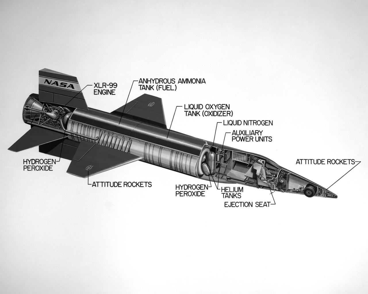
Cutaway drawing of the North American X-15.
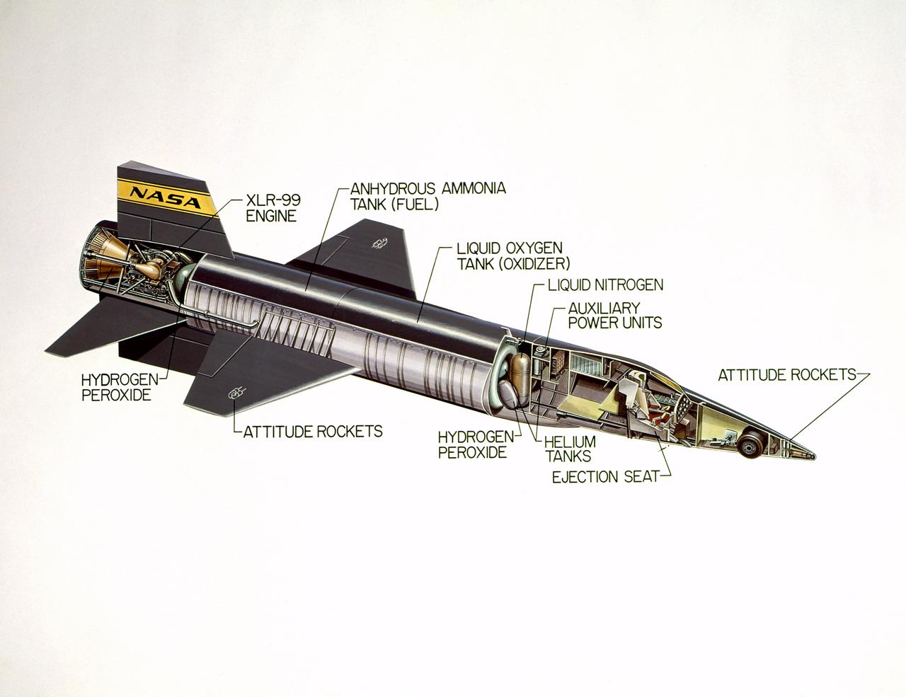
Cutaway drawing of the North American X-15.

<b>RELEASE DATE: OCTOBER 9, 2007</b> <b>Credit: NASA/Goddard Space Flight Center/Reto Stöckli</b> A day’s clouds. The shape and texture of the land. The living ocean. City lights as a beacon of human presence across the globe. This amazingly beautiful view of Earth from space is a fusion of science and art, a showcase for the remote-sensing technology that makes such views possible, and a testament to the passion and creativity of the scientists who devote their careers to understanding how land, ocean, and atmosphere—even life itself—interact to generate Earth’s unique (as far as we know!) life-sustaining environment. Drawing on data from multiple satellite missions (not all collected at the same time), a team of NASA scientists and graphic artists created layers of global data for everything from the land surface, to polar sea ice, to the light reflected by the chlorophyll in the billions of microscopic plants that grow in the ocean. They wrapped these layers around a globe, set it against a black background, and simulated the hazy edge of the Earth’s atmosphere (the limb) that appears in astronaut photography of the Earth. The land surface layer is based on photo-like surface reflectance observations (reflected sunlight) measured by the Moderate Resolution Imaging Spectroradiometer (MODIS) on NASA’s Terra satellite in July 2004. The sea ice layer near the poles comes from Terra MODIS observations of daytime sea ice observed between August 28 and September 6, 2001. The ocean layer is a composite. In shallow water areas, the layer shows surface reflectances observed by Terra MODIS in July 2004. In the open ocean, the photo-like layer is overlaid with observations of the average ocean chlorophyll content for 2004. NASA’s Aqua MODIS collected the chlorophyll data. The cloud layer shows a single-day snapshot of clouds observed by Terra MODIS across the planet on July 29, 2001. City lights on Earth’s night side are visualized from data collected by the Defense Meteorological Satellite Program mission between 1994–1995. The topography layer is based on radar data collected by the Space Shuttle Endeavour during an 11-day mission in February of 2000. Topography over Antarctica comes from the Radarsat Antarctic Mapping Project, version 2. Most of the data layers in this visualization are available as monthly composites as part of NASA’s Blue Marble Next Generation image collection. The images in the collection appear in cylindrical projection (rectangular maps), and they are available at 500-meter resolution. The large images provided above are the full-size versions of these globes. In their hope that these images will inspire people to appreciate the beauty of our home planet and to learn about the Earth system, the developers of these images encourage readers to re-use and re-publish the images freely. NASA images by Reto Stöckli, based on data from NASA and NOAA. To learn the history of the Blue Marble go here: <a href="http://earthobservatory.nasa.gov/Features/BlueMarble/BlueMarble_history.php" rel="nofollow">earthobservatory.nasa.gov/Features/BlueMarble/BlueMarble_...</a> To learn more about the Blue Marble go here: <a href="http://earthobservatory.nasa.gov/IOTD/view.php?id=8108" rel="nofollow">earthobservatory.nasa.gov/IOTD/view.php?id=8108</a> <b><a href="http://www.nasa.gov/centers/goddard/home/index.html" rel="nofollow">NASA Goddard Space Flight Center</a></b> is home to the nation's largest organization of combined scientists, engineers and technologists that build spacecraft, instruments and new technology to study the Earth, the sun, our solar system, and the universe. <b>Follow us on <a href="http://twitter.com/NASA_GoddardPix" rel="nofollow">Twitter</a></b> <b>Join us on <a href="http://www.facebook.com/pages/Greenbelt-MD/NASA-Goddard/395013845897?ref=tsd" rel="nofollow">Facebook</a><b> </b></b>
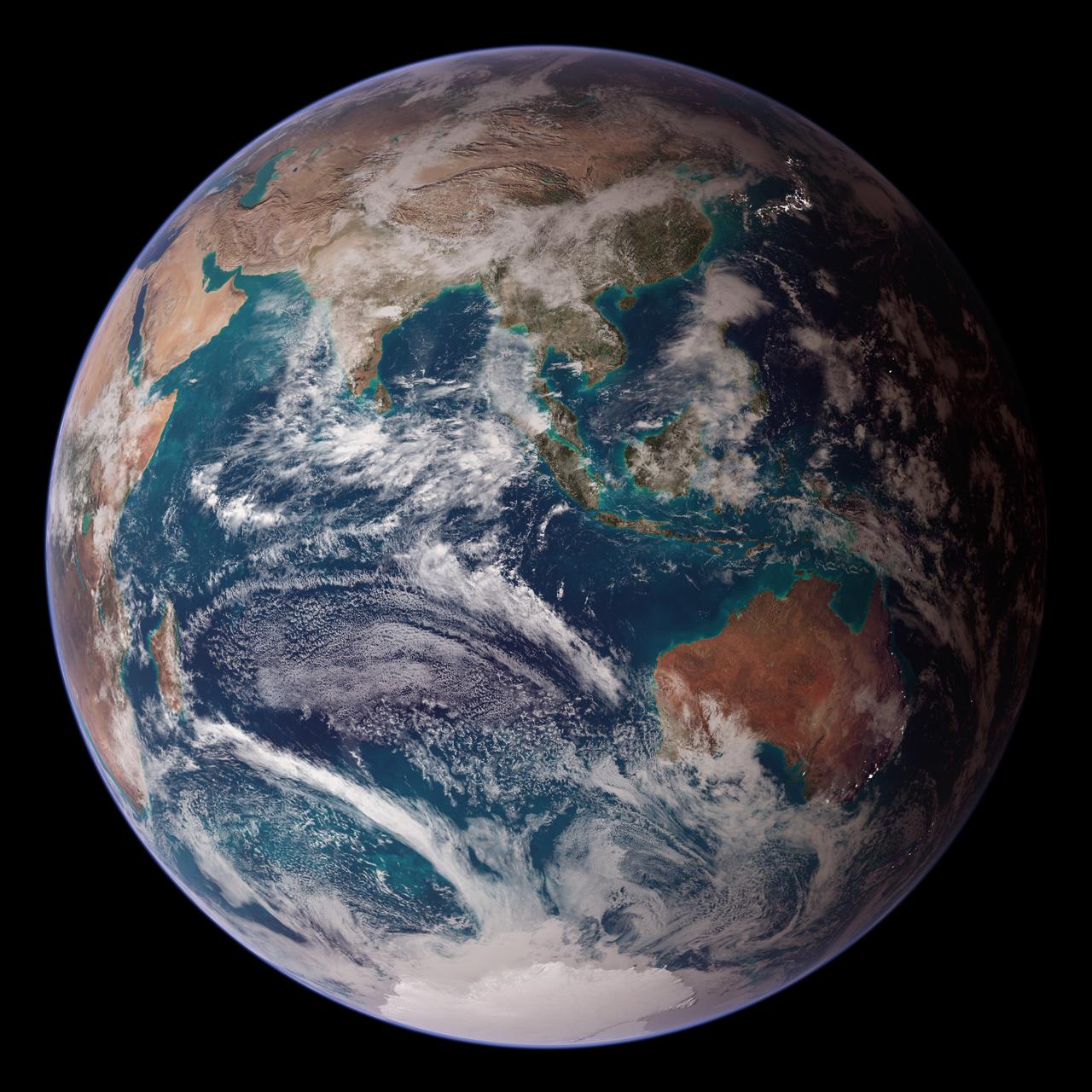
<b>RELEASE DATE: OCTOBER 9, 2007</b> <b>Credit: NASA/Goddard Space Flight Center/Reto Stöckli</b> A day’s clouds. The shape and texture of the land. The living ocean. City lights as a beacon of human presence across the globe. This amazingly beautiful view of Earth from space is a fusion of science and art, a showcase for the remote-sensing technology that makes such views possible, and a testament to the passion and creativity of the scientists who devote their careers to understanding how land, ocean, and atmosphere—even life itself—interact to generate Earth’s unique (as far as we know!) life-sustaining environment. Drawing on data from multiple satellite missions (not all collected at the same time), a team of NASA scientists and graphic artists created layers of global data for everything from the land surface, to polar sea ice, to the light reflected by the chlorophyll in the billions of microscopic plants that grow in the ocean. They wrapped these layers around a globe, set it against a black background, and simulated the hazy edge of the Earth’s atmosphere (the limb) that appears in astronaut photography of the Earth. The land surface layer is based on photo-like surface reflectance observations (reflected sunlight) measured by the Moderate Resolution Imaging Spectroradiometer (MODIS) on NASA’s Terra satellite in July 2004. The sea ice layer near the poles comes from Terra MODIS observations of daytime sea ice observed between August 28 and September 6, 2001. The ocean layer is a composite. In shallow water areas, the layer shows surface reflectances observed by Terra MODIS in July 2004. In the open ocean, the photo-like layer is overlaid with observations of the average ocean chlorophyll content for 2004. NASA’s Aqua MODIS collected the chlorophyll data. The cloud layer shows a single-day snapshot of clouds observed by Terra MODIS across the planet on July 29, 2001. City lights on Earth’s night side are visualized from data collected by the Defense Meteorological Satellite Program mission between 1994–1995. The topography layer is based on radar data collected by the Space Shuttle Endeavour during an 11-day mission in February of 2000. Topography over Antarctica comes from the Radarsat Antarctic Mapping Project, version 2. Most of the data layers in this visualization are available as monthly composites as part of NASA’s Blue Marble Next Generation image collection. The images in the collection appear in cylindrical projection (rectangular maps), and they are available at 500-meter resolution. The large images provided above are the full-size versions of these globes. In their hope that these images will inspire people to appreciate the beauty of our home planet and to learn about the Earth system, the developers of these images encourage readers to re-use and re-publish the images freely. NASA images by Reto Stöckli, based on data from NASA and NOAA. To learn the history of the Blue Marble go here: <a href="http://earthobservatory.nasa.gov/Features/BlueMarble/BlueMarble_history.php" rel="nofollow">earthobservatory.nasa.gov/Features/BlueMarble/BlueMarble_...</a> To learn more about the Blue Marble go here: <a href="http://earthobservatory.nasa.gov/IOTD/view.php?id=8108" rel="nofollow">earthobservatory.nasa.gov/IOTD/view.php?id=8108</a> To learn more about NASA's Goddard Space Flight Center go here: <a href="http://www.nasa.gov/centers/goddard/home/index.html" rel="nofollow">www.nasa.gov/centers/goddard/home/index.html</a> <b><a href="http://www.nasa.gov/centers/goddard/home/index.html" rel="nofollow">NASA Goddard Space Flight Center</a></b> is home to the nation's largest organization of combined scientists, engineers and technologists that build spacecraft, instruments and new technology to study the Earth, the sun, our solar system, and the universe. <b><a href="http://www.nasa.gov/centers/goddard/home/index.html" rel="nofollow">NASA Goddard Space Flight Center</a></b> is home to the nation's largest organization of combined scientists, engineers and technologists that build spacecraft, instruments and new technology to study the Earth, the sun, our solar system, and the universe. <b>Follow us on <a href="http://twitter.com/NASA_GoddardPix" rel="nofollow">Twitter</a></b> <b>Join us on <a href="http://www.facebook.com/pages/Greenbelt-MD/NASA-Goddard/395013845897?ref=tsd" rel="nofollow">Facebook</a><b> </b></b>