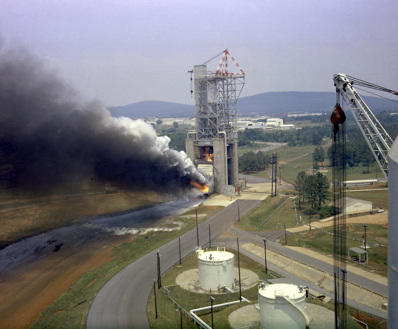
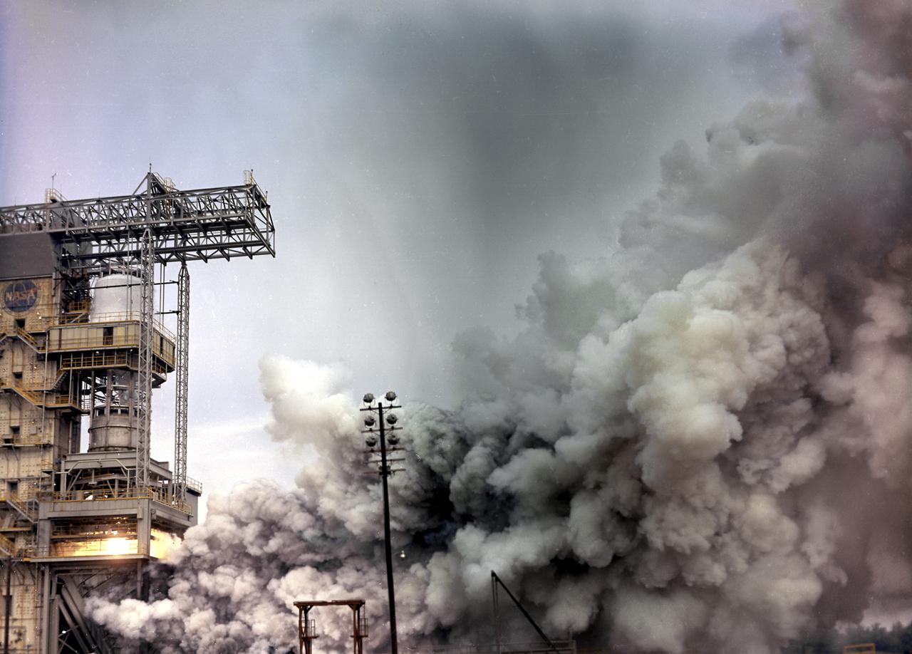
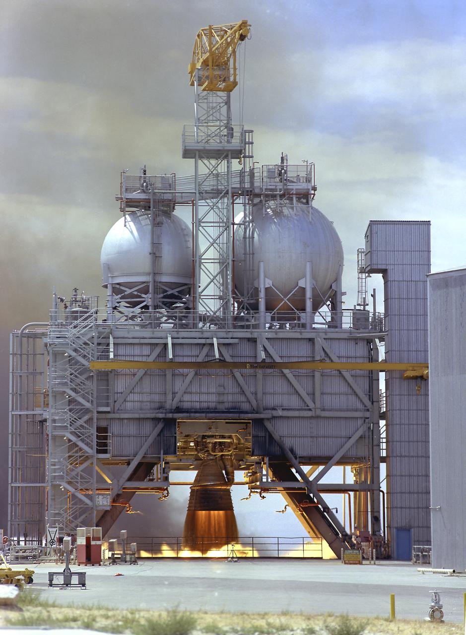
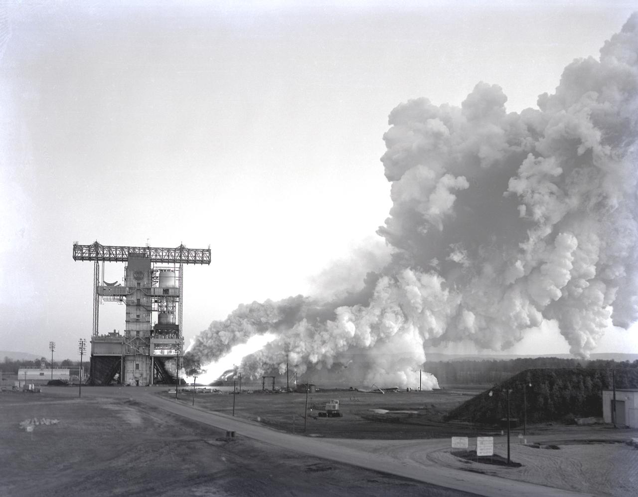
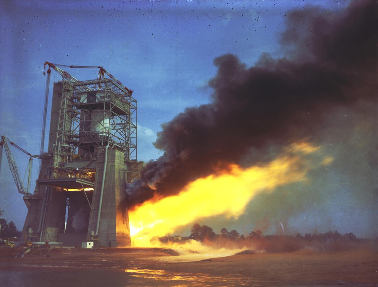
This photograph depicts a test firing of an F-1 engine at the F-1 engine test stand in the west test area of the Marshall Space Flight Center. This engine produced 1,500,000 pounds of thrust using liquid oxygen and RP-1, which is a derivative of kerosene. The F-1 engine test stand was constructed in 1963 to assist in the development of the F-1 engine.
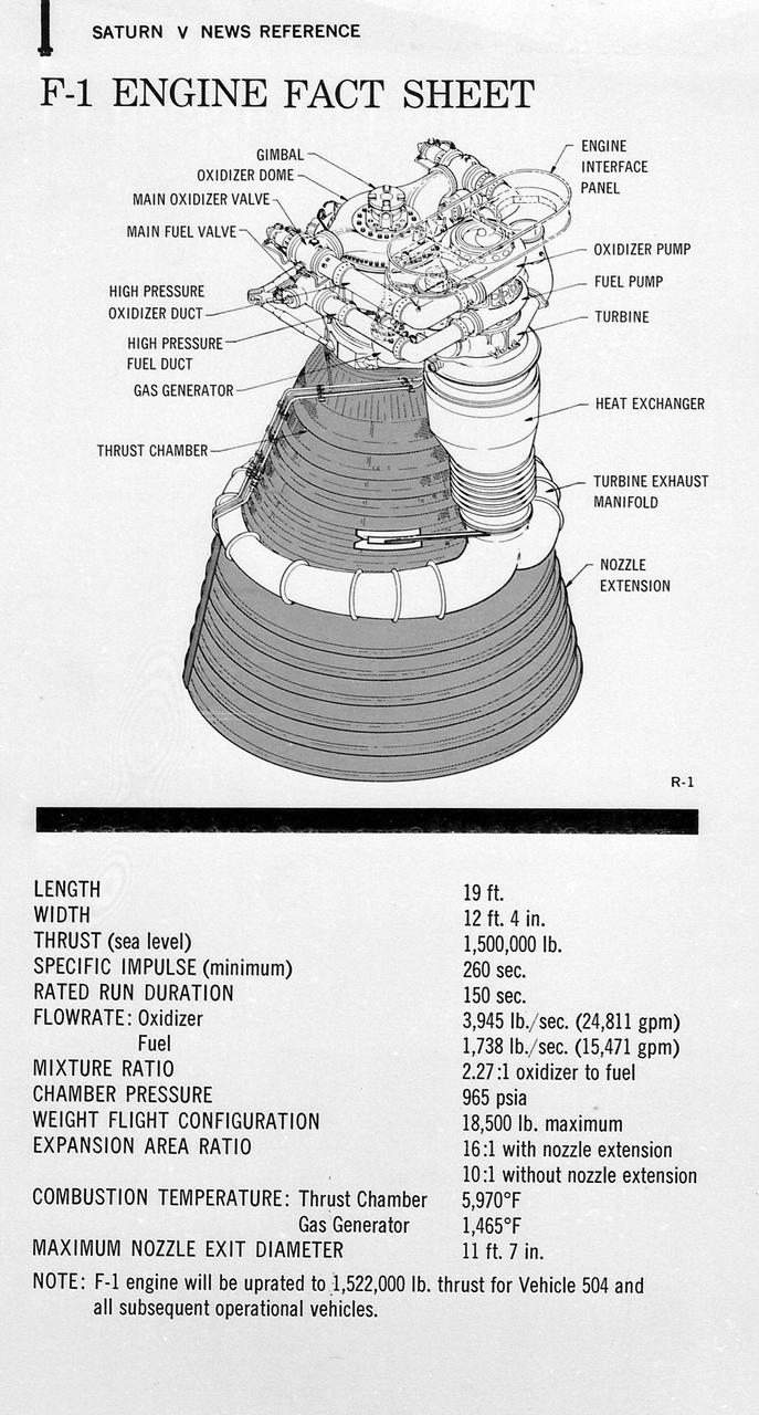
This figure is a drawing of the F-1 engine with callouts of the major components and the engine characteristics.
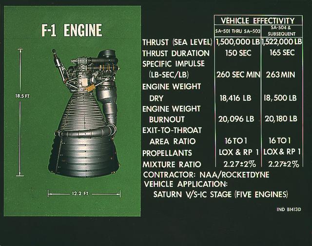
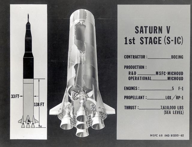
This chart provides the vital statistics for the F-1 rocket engine. Developed by Rocketdyne, under the direction of the Marshall Space Flight Center, the F-1 engine was utilized in a cluster of five engines to propel the Saturn V's first stage, the S-IC. Liquid oxygen and kerosene were used as its propellant. Initially rated at 1,500,000 pounds of thrust, the engine was later uprated to 1,522,000 pounds of thrust after the third Saturn V launch (Apollo 8, the first marned Saturn V mission) in December 1968. The cluster of five F-1 engines burned over 15 tons of propellant per second, during its two and one-half minutes of operation, to take the vehicle to a height of about 36 miles and to a speed of about 6,000 miles per hour.
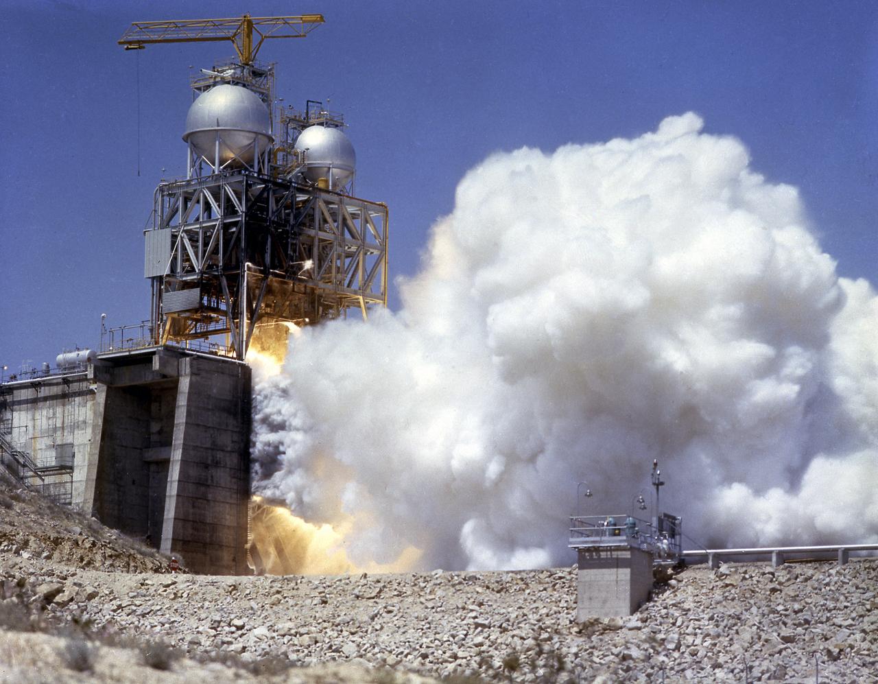
This photograph depicts the Rocketdyne static firing of the F-1 engine at the towering 76-meter Test Stand 1-C in Area 1-125 of the Edwards Air Force Base in California. The Saturn V S-IC (first) stage utilized five F-1 engines for its thrust. Each engine provided 1,500,000 pounds, for a combined thrust of 7,500,000 pounds with liquid oxygen and kerosene as its propellants.
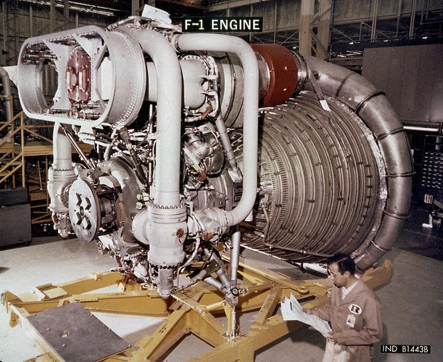
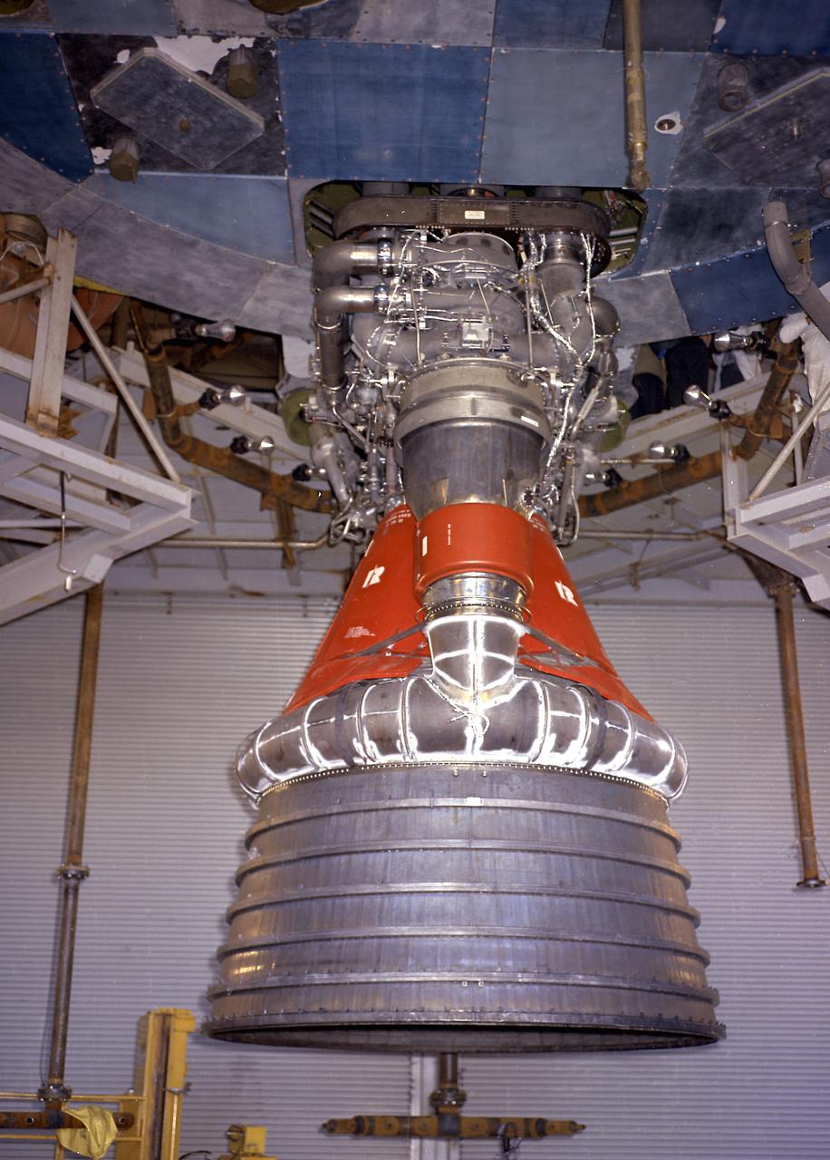
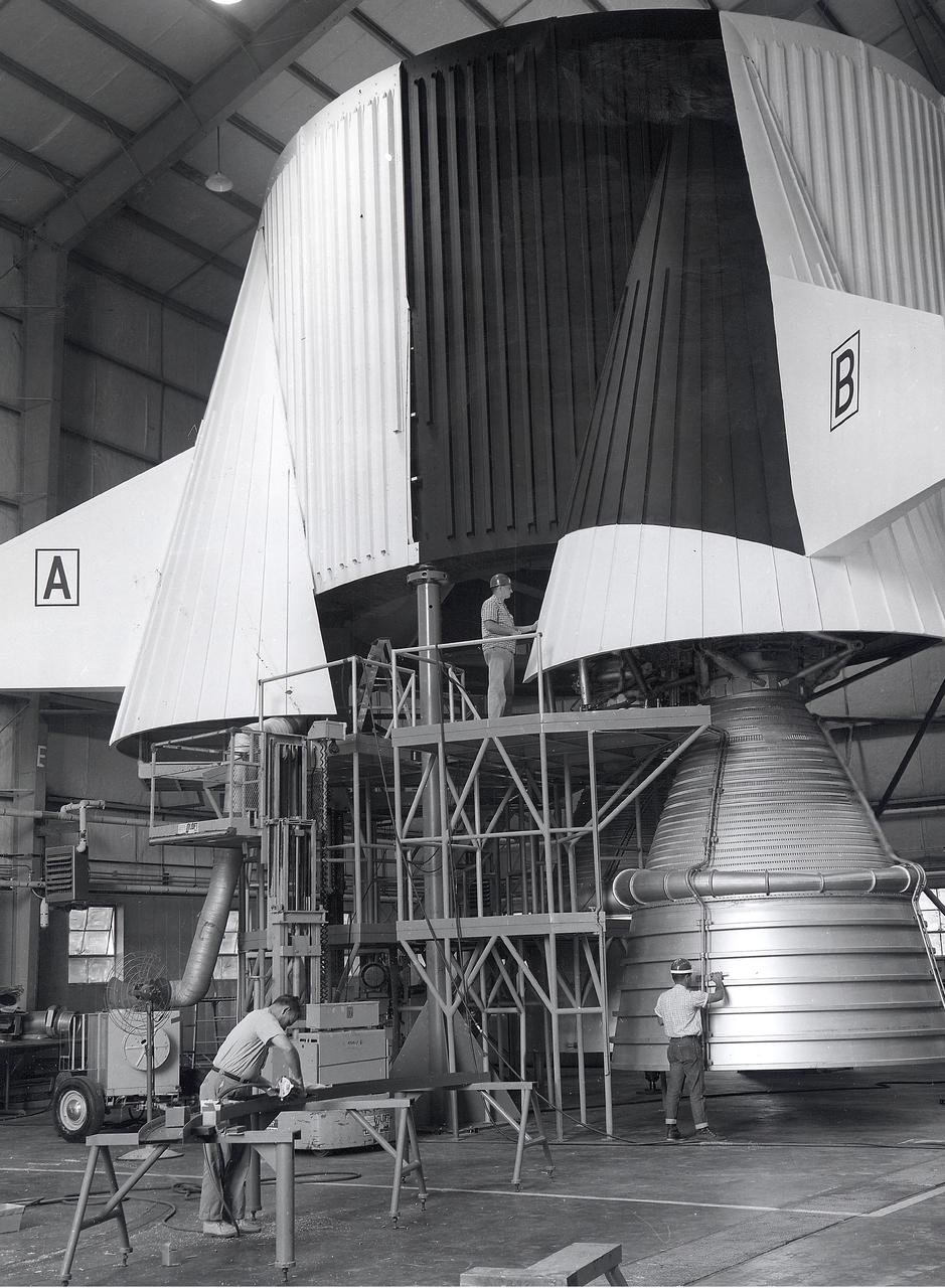
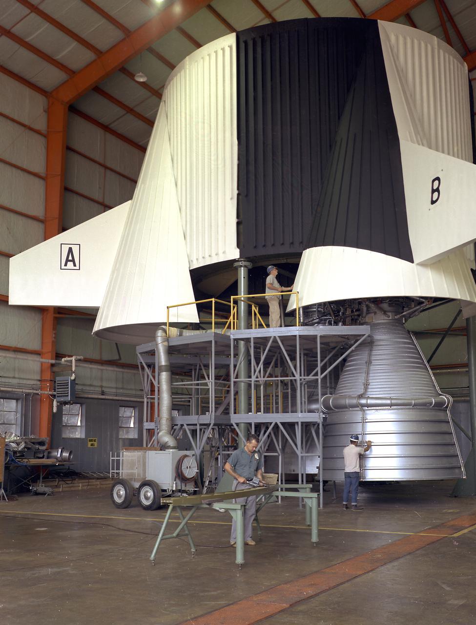
This close-up view of the F-1 engine for the Saturn V S-IC (first) stage shows the engine's complexity, and also its large size as it dwarfs the technician. Developed by Rocketdyne, under the direction of the Marshall Space Flight Center, the F-1 engine was utilized in a cluster of five engines to propel the Saturn V's first stage, the S-IC. Liquid oxygen and kerosene were used as its propellant. Initially rated at 1,500,000 pounds of thrust, the engine was later uprated to 1,522,000 pounds of thrust after the third Saturn V launch (Apollo 8, the first marned Saturn V mission) in December 1968. The cluster of five F-1 engines burned over 15 tons of propellant per second, during its two and one-half minutes of operation, to take the vehicle to a height of about 36 miles and to a speed of about 6,000 miles per hour.
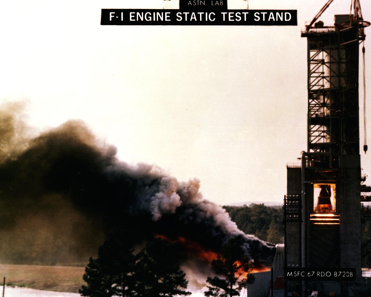
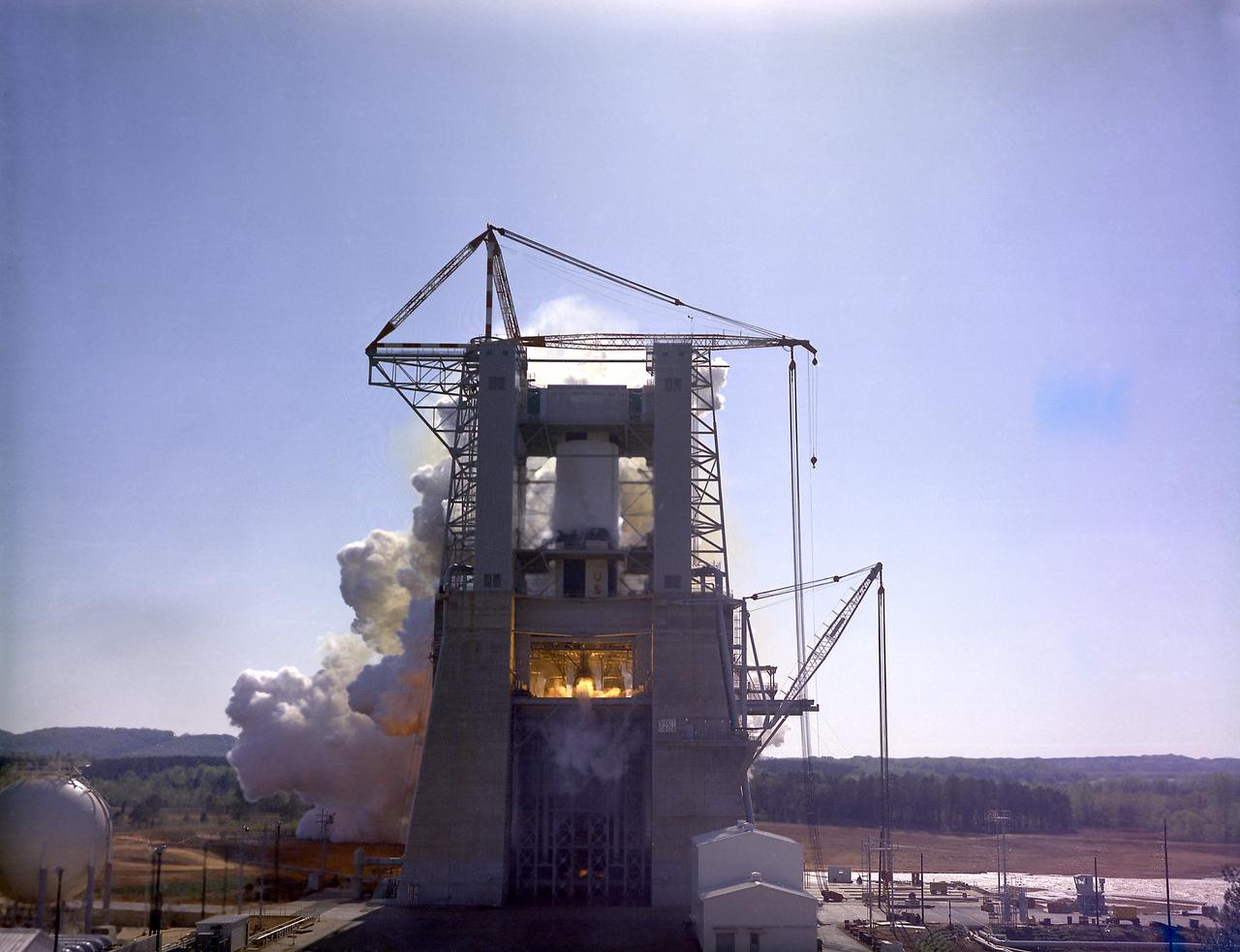
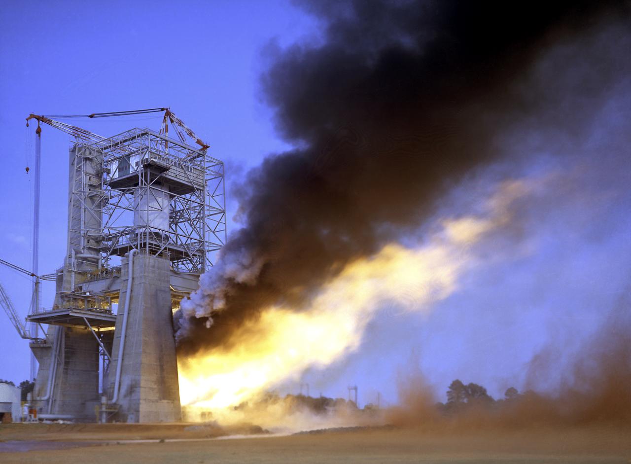
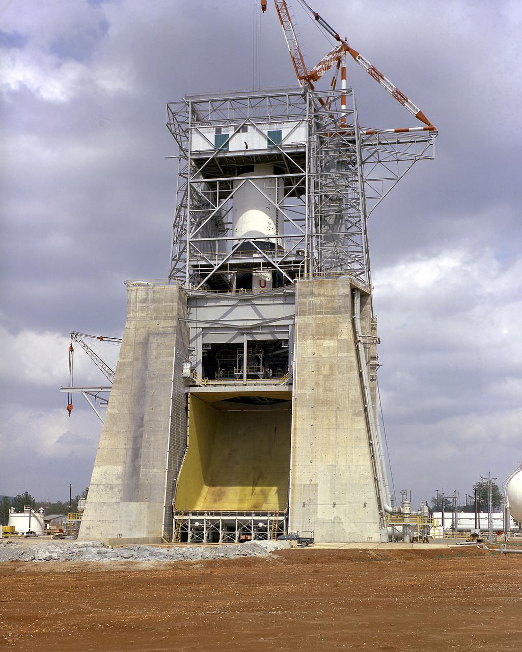
This photograph depicts the F-1 engine firing in the Marshall Space Flight Center’s F-1 Engine Static Test Stand. Construction of the S-IC Static test stand complex began in 1961 in the west test area of MSFC, and was completed in 1964. It is a vertical engine firing test stand, 239 feet in elevation and 4,600 square feet in area at the base, designed to assist in the development of the F-1 Engine. Capability is provided for static firing of 1.5 million pounds of thrust using liquid oxygen and kerosene. The foundation of the stand is keyed into the bedrock approximately 40 feet below grade.
The static firing of a Saturn F-1 engine at the Marshall Space Flight Center's Static Test Stand. The F-1 engine is a single-start, 1,5000,000 Lb fixed-thrust, bipropellant rocket system. The engine uses liquid oxygen as the oxidizer and RP-1 (kerosene) as fuel. The five-engine cluster used on the first stage of the Saturn V produces 7,500,000 lbs of thrust.
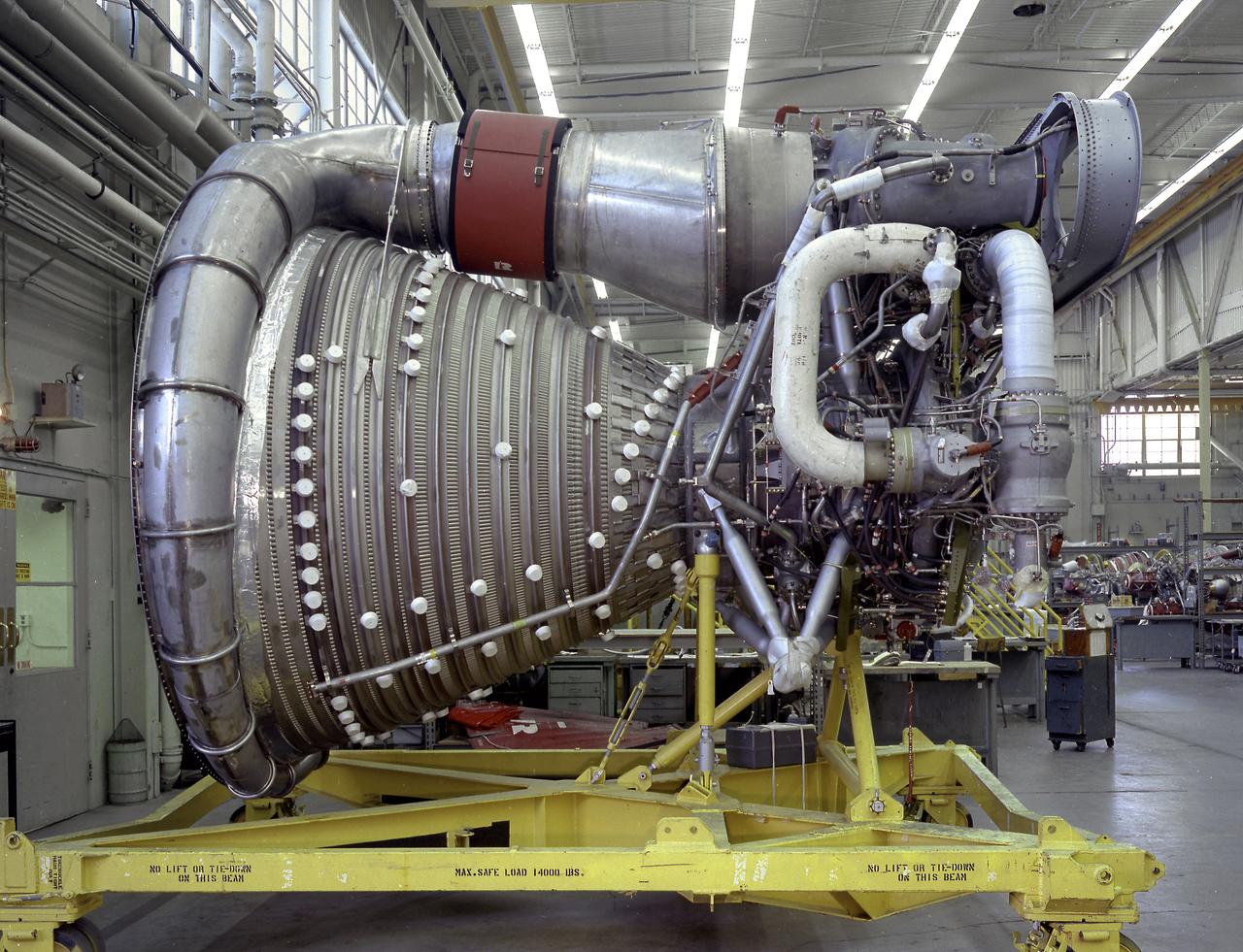
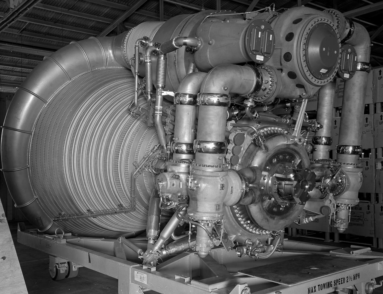
A complete F-1 engine assembly is shown in this photograph. Designed and developed by Rocketdye under the direction of the Marshall Space Flight Center, the engine measured 19-feet tall by 12.5 feet at the nozzle exit, and each engine produced a 1,500,000-pound thrust using liquid oxygen and kerosene as the propellant. A cluster of five F-1 engines was mounted on the Saturn V S-IC (first) stage and burned 15 tons of liquid oxygen and kerosene each second to produce 7,500,000 pounds of thrust.
The F-1 engine was developed and built by Rocketdyne under the direction of the Marshall Space Flight Center. It measured 19 feet tall by 12.5 feet at the nozzle exit, and produced a 1,500,000-pound thrust using liquid oxygen and kerosene as the propellant. The image shows an F-1 engine being test fired at the Test Stand 1-C at the Edwards Air Force Base in California.
Engineers at the Marshall Space Flight Center install the F-1 engines on the S-IC stage thrust structure at the S-IC static test stand. Engines are installed on the stage after it has been placed in the test stand. This image shows a close-up of an F-1 engine. Five F-1 engines, each weighing 10 tons, gave the booster a total thrust of 7,500,000 pounds, roughly equivalent to 160 million horsepower.
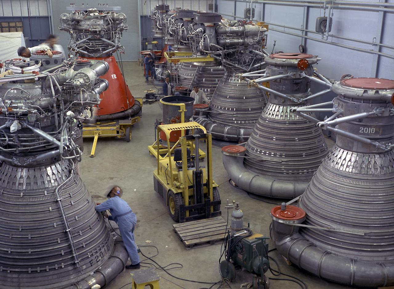
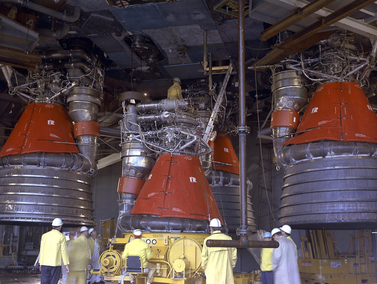
This photograph shows F-1 engines being stored in the F-1 Engine Preparation Shop, building 4666, at the Marshall Space Flight Center. Each F-1 engine produced a thrust of 1,500,000 pounds. A cluster of five engines was mounted on the thrust structure of the S-IC stage of a 364-foot long Saturn V launch vehicle that ultimately took astronauts to the Moon.
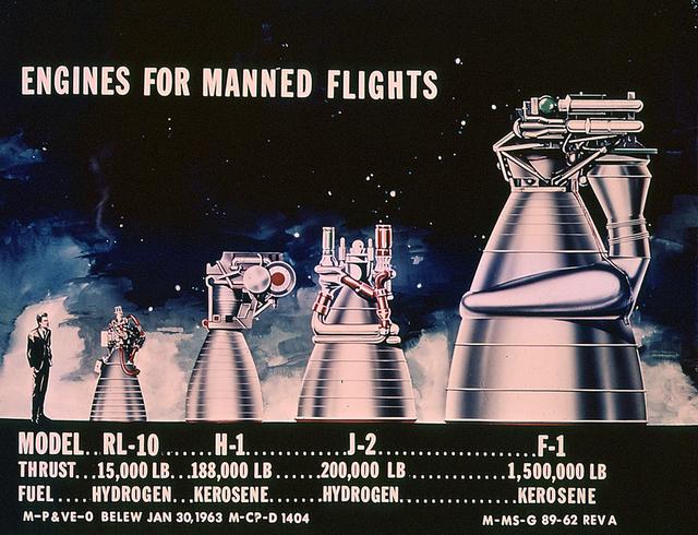
This drawing clearly shows the comparative sizes of the rocket engines used to launch the Saturn vehicles. The RL-10 and the H-1 engines were used to launch the Saturn I rockets. The J-2 engine was used on the second stage of Saturn IB and the second and third stages of Saturn V. The F-1 engine was used on the first stage of the Saturn V.
A close-up view of the F-1 Engine for the Saturn V S-IC (first) stage depicts the complexity of the engine. Developed by Rocketdyne under the direction of the Marshall Space Flight Center, the F-1 engine was utilized in a cluster of five engines to propel the Saturn V's first stage, the S-IC. Liquid oxygen and kerosene were used as its propellant. Initially rated at 1,500,000 pounds of thrust, the engine was later uprated to 1,522,000 pounds of thrust after the third Saturn V launch (Apollo 8, the first marned Saturn V mission) in December 1968. The cluster of five F-1 engines burned over 15 tons of propellant per second, during its two and one-half minutes of operation, to take the vehicle to a height of about 36 miles and to a speed of about 6,000 miles per hour.
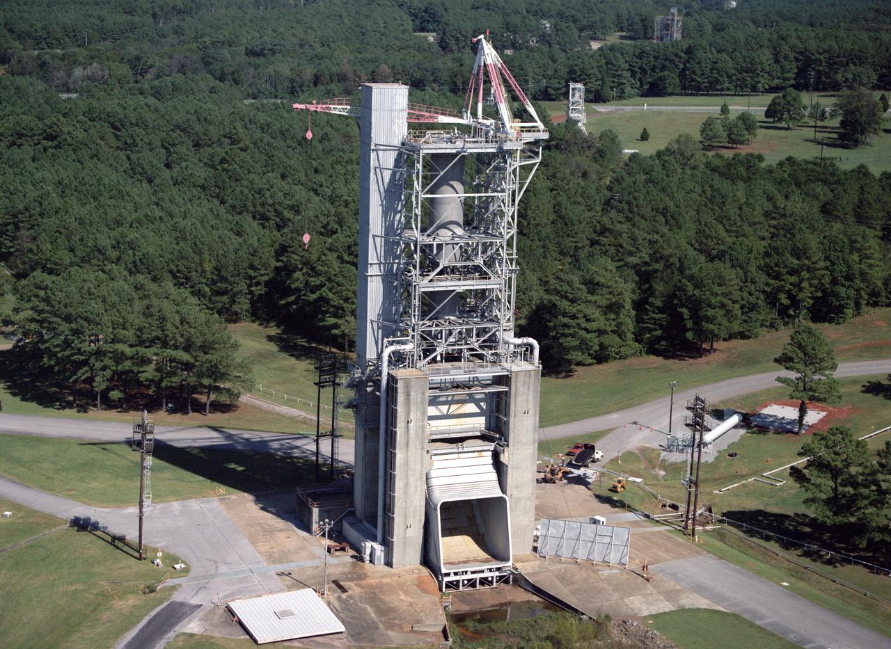
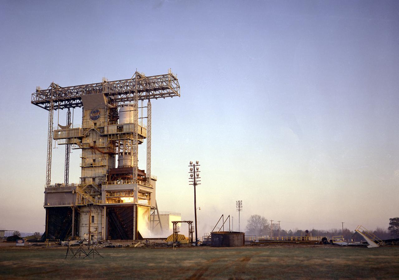
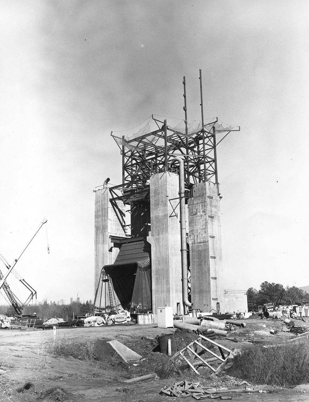
Marshall Space Flight Center's F-1 Engine Test Stand is shown in this picture. Constructed in 1963, the test stand is a vertical engine firing test stand, 239 feet in elevation and 4,600 square feet in area at the base, and was designed to assist in the development of the F-1 Engine. Capability is provided for static firing of 1.5 million pounds of thrust using liquid oxygen and kerosene. The foundation of the stand is keyed into the bedrock approximately 40 feet below grade.
The test laboratory of the Marshall Space Flight Center (MSFC) tested the F-1 engine, the most powerful rocket engine ever fired at MSFC. The engine was tested on the newly modified Saturn IB Static Test Stand which had been used for three years to test the Saturn I eight-engine booster, S-I (first) stage. In 1961 the test stand was modified to permit static firing of the S-I/S-IB stage and the name of the stand was then changed to the S-IB Static Test Stand. Producing a combined thrust of 7,500,000 pounds, five F-1 engines powered the S-IC (first) stage of the Saturn V vehicle for the marned lunar mission.
The test laboratory of the Marshall Space Flight Center (MSFC) tested the F-1 engine, the most powerful rocket engine ever fired at MSFC. The engine was tested on the newly modified Saturn IB static test stand that had been used for three years to test the Saturn I eight-engine booster, S-I (first) stage. In 1961, the test stand was modified to permit static firing of the S-I/S-IB stage and the name of the stand was then changed to the S-IB Static Test Stand. Producing a combined thrust of 7,500,000 pounds, five F-1 engines powered the S-IC (first) stage of the Saturn V vehicle for the marned lunar mission.
Engineers and technicians at the Marshall Space Flight Center were installing an F-I engine on the Saturn V S-IC (first) stage thrust structure in building 4705. The S-IC (first) stage used five F-1 engines that produced a total thrust of 7,500,000 pounds as each engine produced 1,500,000 pounds of thrust. The S-IC stage lifted the Saturn V vehicle and Apollo spacecraft from the launch pad.
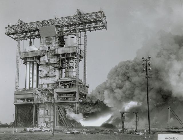
The flame and exhaust from the test firing of an F-1 engine blast out from the Saturn S-IB Static Test Stand in the east test area of the Marshall Space Flight Center. A Cluster of five F-1 engines, located in the S-IC (first) stage of the Saturn V vehicle, provided over 7,500,000 pounds of thrust to launch the giant rocket. The towering 363-foot Saturn V was a multistage, multiengine launch vehicle standing taller than the Statue of Liberty. Altogether, the Saturn V engines produced as much power as 85 Hoover Dams.
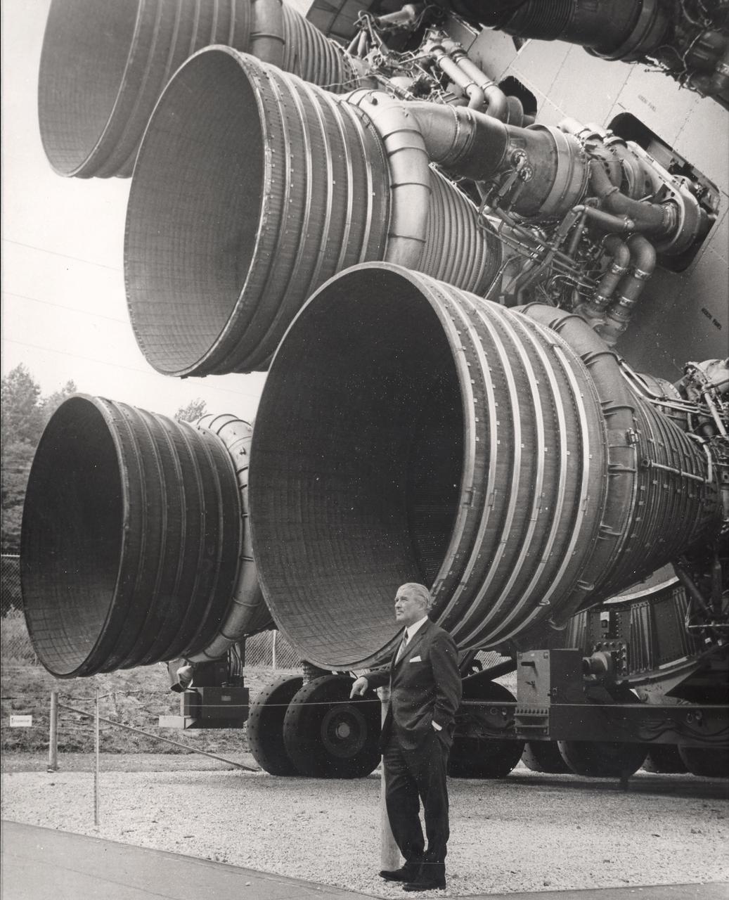
A pioneer of America's space program, Dr. von Braun stands by the five F-1 engines of the Saturn V launch vehicle. This Saturn V vehicle is an actual test vehicle which has been displayed at the U.S. Space Rocket Center in Huntsville, Alabama. Designed and developed by Rocketdyne under the direction of the Marshall Space Flight Center, a cluster of five F-1 engines was mounted on the Saturn V S-IC (first) stage. The engines measured 19-feet tall by 12.5-feet at the nozzle exit and burned 15 tons of liquid oxygen and kerosene each second to produce 7,500,000 pounds of thrust. The S-IC stage is the first stage, or booster, of a 364-foot long rocket that ultimately took astronauts to the Moon.
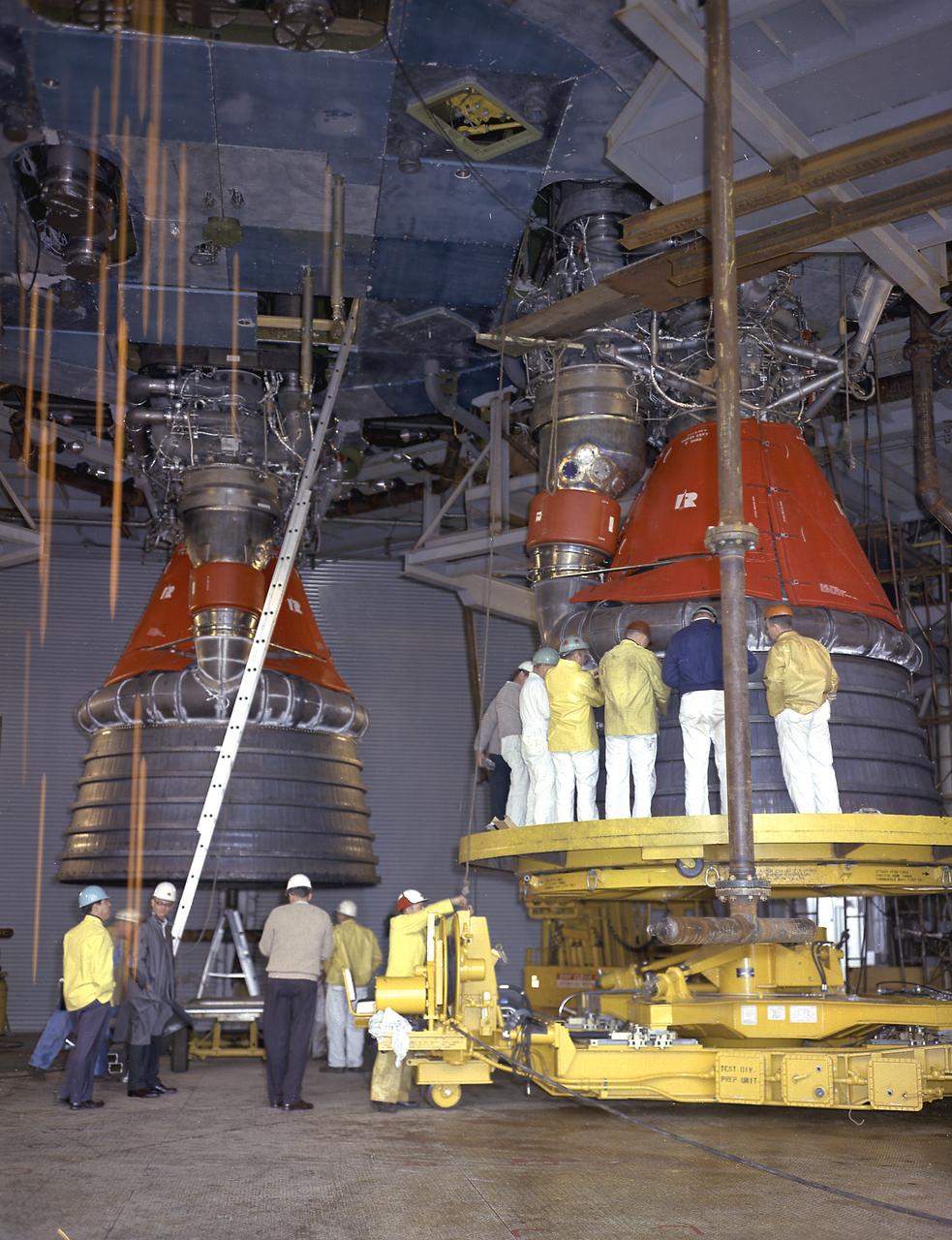
Engineers at the Marshall Space Flight Center install the F-1 engines on the S-IC stage thrust structure at the S-IC static test stand. Engines are installed on the stage after it has been placed in the test stand. Five F-1 engines, each weighing 10 tons, gave the booster a total thrust of 7,500,000 pounds, roughly equivalent to 160 million horsepower.
Engineers at the Marshall Space Flight Center install the F-1 engines on the S-IC stage thrust structure at the S-IC static test stand. Engines are installed on the stage after it has been placed in the test stand. Five F-1 engines, each weighing 10 tons, gave the booster a total thrust of 7,500,000 pounds, roughly equivalent to 160 million horsepower.
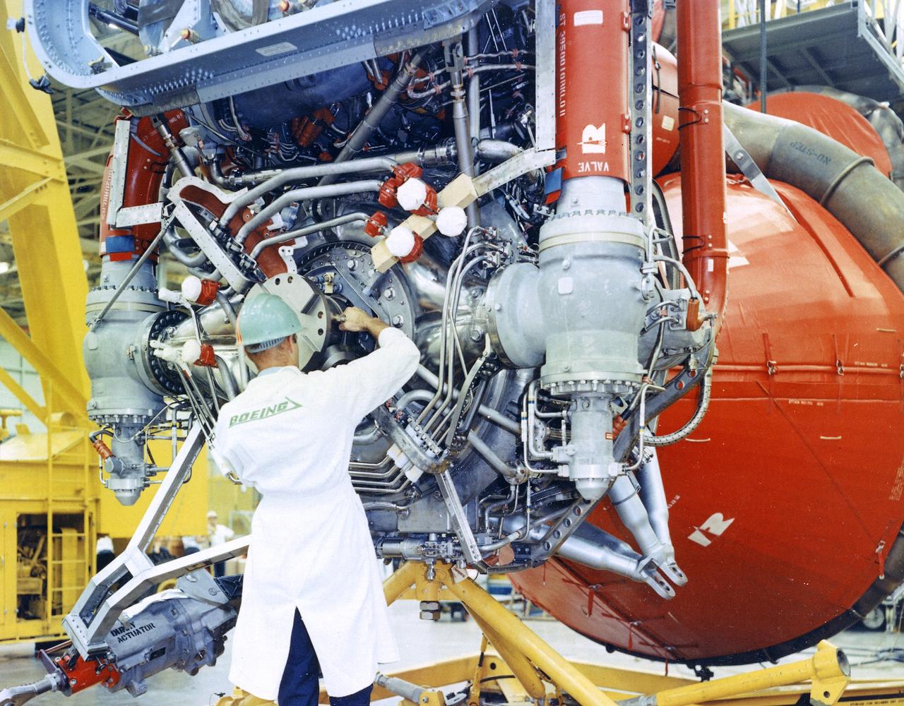
This image depicts a Boeing worker installing an F-1 engine on the Saturn V S-IC flight stage at the Michoud Assembly Facility (MAF). The Saturn IB and Saturn V first stages were manufactured at the MAF, located 24 kilometers (approximately 15 miles) east of downtown New Orleans, Louisiana. The prime contractors, Chrysler and Boeing, jointly occupied the MAF. The basic manufacturing building boasted 43 acres under one roof. By 1964, NASA added a separate engineering and office building, vertical assembly building, and test stage building.
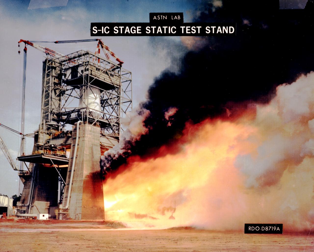
The Saturn V first stages were test fired at the Mississippi Test Facility and at the Marshall Space Flight Center (MSFC). Five F-1 engines powered the first stage, each developing 1.5 million pounds of thrust. The first stage, known as the S-IC stage, burned over 15 tons of propellant per second during its 2.5 minutes of operation to take the vehicle to a height of about 36 miles and to a speed of about 6,000 miles per hour. The stage was 138 feet long and 33 feet in diameter. This photograph shows the test firing of an F-1 engine at the MSFC's S-IC Static Test Firing Facility.
This photograph depicts a dramatic view of the first test firing of all five F-1 engines for the Saturn V S-IC stage at the Marshall Space Flight Center. The testing lasted a full duration of 6.5 seconds. It also marked the first test performed in the new S-IC static test stand and the first test using the new control blockhouse. The S-IC stage is the first stage, or booster, of a 364-foot long rocket that ultimately took astronauts to the Moon. Operating at maximum power, all five of the engines produced 7,500,000 pounds of thrust. Required to hold down the brute force of a 7,500,000-pound thrust, the S-IC static test stand was designed and constructed with the strength of hundreds of tons of steel and cement, planted down to bedrock 40 feet below ground level. The structure was topped by a crane with a 135-foot boom. With the boom in the up position, the stand was given an overall height of 405 feet, placing it among the highest structures in Alabama at the time. When the Saturn V S-IC first stage was placed upright in the stand , the five F-1 engine nozzles pointed downward on a 1,900 ton, water-cooled deflector. To prevent melting damage, water was sprayed through small holes in the deflector at the rate 320,000 gallons per minute.
This photograph depicts a view of the test firing of all five F-1 engines for the Saturn V S-IC test stage at the Marshall Space Flight Center. The S-IC stage is the first stage, or booster, of a 364-foot long rocket that ultimately took astronauts to the Moon. Operating at maximum power, all five of the engines produced 7,500,000 pounds of thrust. The S-IC Static Test Stand was designed and constructed with the strength of hundreds of tons of steel and cement, planted down to bedrock 40 feet below ground level, and was required to hold down the brute force of the 7,500,000-pound thrust. The structure was topped by a crane with a 135-foot boom. With the boom in the up position, the stand was given an overall height of 405 feet, placing it among the highest structures in Alabama at the time. When the Saturn V S-IC first stage was placed upright in the stand , the five F-1 engine nozzles pointed downward on a 1,900-ton, water-cooled deflector. To prevent melting damage, water was sprayed through small holes in the deflector at the rate 320,000 gallons per minutes.
This photograph depicts a view of the test firing of all five F-1 engines for the Saturn V S-IC test stage at the Marshall Space Flight Center. The S-IC stage is the first stage, or booster, of a 364-foot long rocket that ultimately took astronauts to the Moon. Operating at maximum power, all five of the engines produced 7,500,000 pounds of thrust. The S-IC Static Test Stand was designed and constructed with the strength of hundreds of tons of steel and cement, planted down to bedrock 40 feet below ground level, and was required to hold down the brute force of the 7,500,000-pound thrust. The structure was topped by a crane with a 135-foot boom. With the boom in the up position, the stand was given an overall height of 405 feet, placing it among the highest structures in Alabama at the time. When the Saturn V S-IC first stage was placed upright in the stand , the five F-1 engine nozzles pointed downward on a 1,900-ton, water-cooled deflector. To prevent melting damage, water was sprayed through small holes in the deflector at the rate 320,000 gallons per minutes
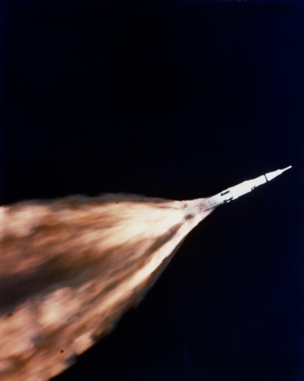
S68-27365 (4 April 1968) --- The five F-1 engines of the huge Apollo/Saturn V space vehicle's first (S-IC) stage leave a gigantic trail of flame in the sky above the Kennedy Space Center seconds after liftoff. The launch of the Apollo 6 (Spacecraft 020/Saturn 502) unmanned space mission occurred at 07:00:01.5 (EST), April 4, 1968. This view of the Apollo 6 launch was taken from a chase plane.
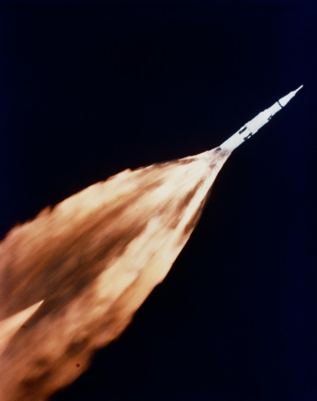
S68-27366 (4 April 1968) --- The five F-1 engines of the huge Apollo/Saturn V space vehicle's first (S-IC) stage leave a gigantic trail of flame in the sky above the Kennedy Space Center seconds after liftoff. The launch of the Apollo 6 (Spacecraft 020/Saturn 502) unmanned space mission occurred at 07:00:01.5 (EST), April 4, 1968. This view of the Apollo 6 launch was taken from a chase plane.
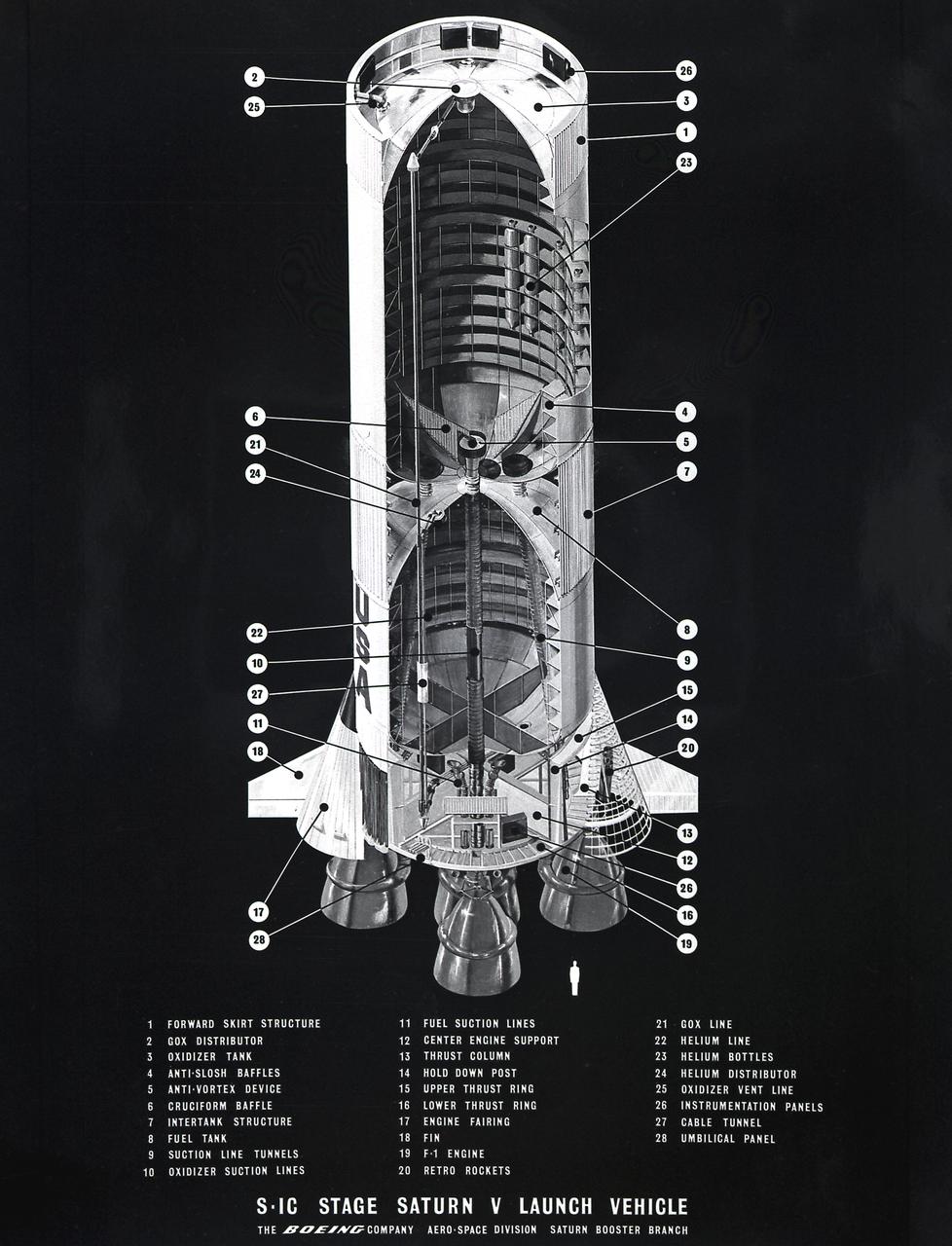
This is a cutaway view of the Saturn V first stage, known as the S-IC, detailing the five F-1 engines and fuel cells. The S-IC stage is 138 feet long and 33 feet in diameter, producing more than 7,500,000 pounds of thrust through the five F-1 engines that are powered by liquid oxygen and kerosene. Four of the engines are mounted on an outer ring and gimbal for control purposes. The fifth engine is rigidly mounted in the center. When ignited, the roar produced by the five engines equals the sound of 8,000,000 hi-fi sets.
This photograph depicts Marshall Space Flight Center employees, James Reagin, machinist (top); Floyd McGinnis, machinist; and Ernest Davis, experimental test mechanic (foreground), working on a mock up of the S-IC thrust structure. The S-IC stage is the first stage, or booster, of the 364-foot long Saturn V rocket that ultimately took astronauts to the Moon. The S-IC stage, burned over 15 tons of propellant per second during its 2.5 minutes of operation to take the vehicle to a height of about 36 miles and to a speed of about 6,000 miles per hour. The stage was 138 feet long and 33 feet in diameter. Operating at maximum power, all five of the engines produced 7,500,000 pounds of thrust.
The S-IC-T stage (static firing stage) is installed and awaits the first static firing of all five F-1 engines at the Marshall Space Flight Center S-IC static test stand. Constructed in 1964, the S-IC static test stand was designed and constructed to develop and test the first stage of the Saturn V launch vehicle that used five F-1 engines. Each F-1 engine developed 1,500,000 pounds of thrust for a total liftoff thrust of 7,500,000 pounds. To handle this research and development effort, the stand contains 12,000,000 pounds of concrete on its base legs that are planted down to bedrock 40 feet below ground level. Of concrete and steel construction, the stand foundation walls are 4 feet thick, and topped by a crane with a 135-foot boom. With the boom in the up position, the stand is given an overall height of 405 feet, placing it among the highest structures in Alabama at the time.
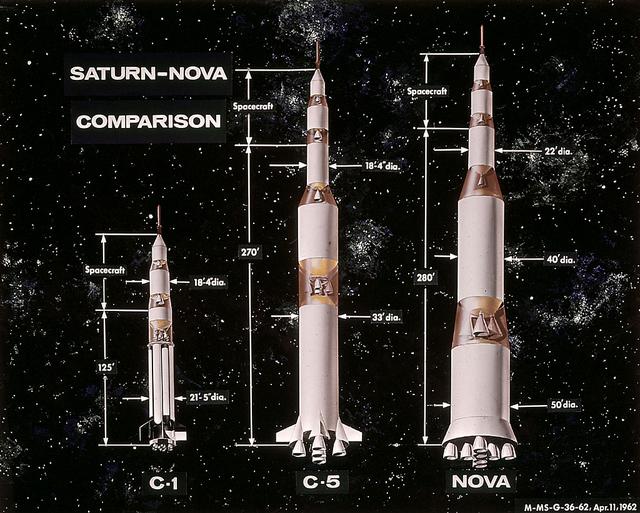
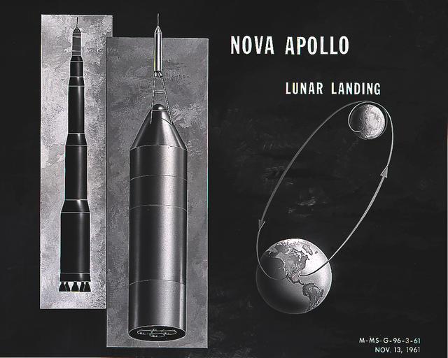
In this 1962 artist's concept , a proposed Nova rocket, shown at right, is compared to a Saturn C-1, left, and a Saturn C-5, center. The Marshall Space Flight Center directed studies of Nova configuration from 1960 to 1962 as a means of achieving a marned lunar landing with a direct flight to the Moon. Various configurations of the vehicle were examined, the largest being a five-stage vehicle using eight F-1 engines in the first stage. Although the program was effectively cancelled in 1962 when NASA planners selected the lunar-orbital rendezvous mode, the proposed F-1 engine was eventually used to propel the first stage of the Saturn V launch vehicle in the Apollo Program.
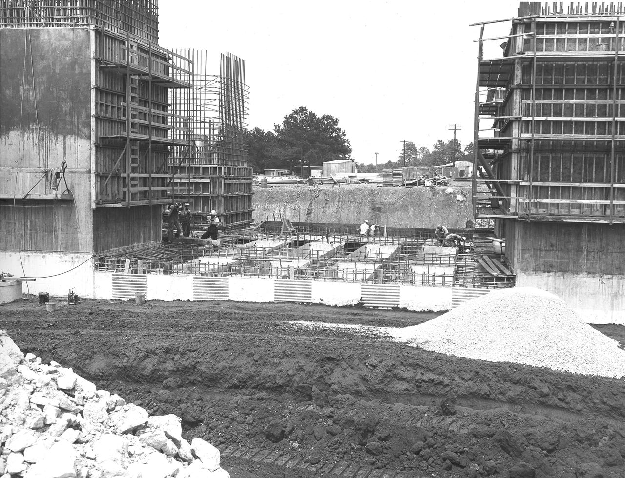
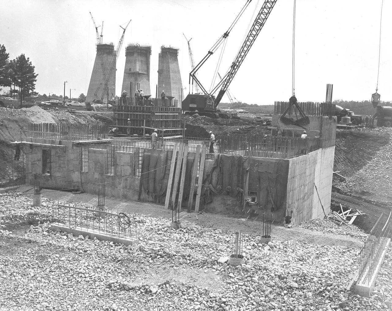
At its founding, the Marshall Space Flight Center (MSFC) inherited the Army’s Jupiter and Redstone test stands, but much larger facilities were needed for the giant stages of the Saturn V. From 1960 to 1964, the existing stands were remodeled and a sizable new test area was developed. The new comprehensive test complex for propulsion and structural dynamics was unique within the nation and the free world, and they remain so today because they were constructed with foresight to meet the future as well as on going needs. Construction of the S-IC Static test stand complex began in 1961 in the west test area of MSFC, and was completed in 1964. The S-IC static test stand was designed to develop and test the 138-ft long and 33-ft diameter Saturn V S-IC first stage, or booster stage, weighing in at 280,000 pounds. Required to hold down the brute force of a 7,500,000-pound thrust produced by 5 F-1 engines, the S-IC static test stand was designed and constructed with the strength of hundreds of tons of steel and 12,000,000 pounds of cement, planted down to bedrock 40 feet below ground level. The foundation walls, constructed with concrete and steel, are 4 feet thick. The base structure consists of four towers with 40-foot-thick walls extending upward 144 feet above ground level. The structure was topped by a crane with a 135-foot boom. With the boom in the upright position, the stand was given an overall height of 405 feet, placing it among the highest structures in Alabama at the time. North of the massive S-IC test stand, the F-1 Engine test stand was built. Designed to assist in the development of the F-1 Engine, the F-1 test stand is a vertical engine firing test stand, 239 feet in elevation and 4,600 square feet in area at the base. Capability was provided for static firing of 1.5 million pounds of thrust using liquid oxygen and kerosene. Like the S-IC stand, the foundation of the F-1 stand is keyed into the bedrock approximately 40 feet below grade. This photo, taken April 4, 1963 depicts the construction of the F-1 test stand foundation walls.
At its founding, the Marshall Space Flight Center (MSFC) inherited the Army’s Jupiter and Redstone test stands, but much larger facilities were needed for the giant stages of the Saturn V. From 1960 to 1964, the existing stands were remodeled and a sizable new test area was developed. The new comprehensive test complex for propulsion and structural dynamics was unique within the nation and the free world, and they remain so today because they were constructed with foresight to meet the future as well as on going needs. Construction of the S-IC Static test stand complex began in 1961 in the west test area of MSFC, and was completed in 1964. The S-IC static test stand was designed to develop and test the 138-ft long and 33-ft diameter Saturn V S-IC first stage, or booster stage, weighing in at 280,000 pounds. Required to hold down the brute force of a 7,500,000-pound thrust produced by 5 F-1 engines, the S-IC static test stand was designed and constructed with the strength of hundreds of tons of steel and 12,000,000 pounds of cement, planted down to bedrock 40 feet below ground level. The foundation walls, constructed with concrete and steel, are 4 feet thick. The base structure consists of four towers with 40-foot-thick walls extending upward 144 feet above ground level. The structure was topped by a crane with a 135-foot boom. With the boom in the upright position, the stand was given an overall height of 405 feet, placing it among the highest structures in Alabama at the time. North of the massive S-IC test stand, the F-1 Engine test stand was built. Designed to assist in the development of the F-1 Engine, the F-1 test stand is a vertical engine firing test stand, 239 feet in elevation and 4,600 square feet in area at the base. Capability was provided for static firing of 1.5 million pounds of thrust using liquid oxygen and kerosene. Like the S-IC stand, the foundation of the F-1 stand is keyed into the bedrock approximately 40 feet below grade. This photo, taken April 17, 1963 depicts the construction of the F-1 test stand foundation walls.
At its founding, the Marshall Space Flight Center (MSFC) inherited the Army’s Jupiter and Redstone test stands, but much larger facilities were needed for the giant stages of the Saturn V. From 1960 to 1964, the existing stands were remodeled and a sizable new test area was developed. The new comprehensive test complex for propulsion and structural dynamics was unique within the nation and the free world, and they remain so today because they were constructed with foresight to meet the future as well as on going needs. Construction of the S-IC Static test stand complex began in 1961 in the west test area of MSFC, and was completed in 1964. The S-IC static test stand was designed to develop and test the 138-ft long and 33-ft diameter Saturn V S-IC first stage, or booster stage, weighing in at 280,000 pounds. Required to hold down the brute force of a 7,500,000-pound thrust produced by 5 F-1 engines, the S-IC static test stand was designed and constructed with the strength of hundreds of tons of steel and 12,000,000 pounds of cement, planted down to bedrock 40 feet below ground level. The foundation walls, constructed with concrete and steel, are 4 feet thick. The base structure consists of four towers with 40-foot-thick walls extending upward 144 feet above ground level. The structure was topped by a crane with a 135-foot boom. With the boom in the upright position, the stand was given an overall height of 405 feet, placing it among the highest structures in Alabama at the time. North of the massive S-IC test stand, the F-1 Engine test stand was built. Designed to assist in the development of the F-1 Engine, the F-1 test stand is a vertical engine firing test stand, 239 feet in elevation and 4,600 square feet in area at the base. Capability was provided for static firing of 1.5 million pounds of thrust using liquid oxygen and kerosene. Like the S-IC stand, the foundation of the F-1 stand is keyed into the bedrock approximately 40 feet below grade. This photo, taken April 4, 1963 depicts the construction of the F-1 test stand foundation walls.
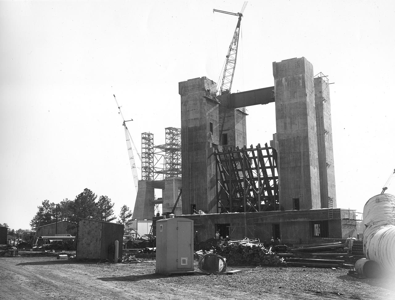
At its founding, the Marshall Space Flight Center (MSFC) inherited the Army’s Jupiter and Redstone test stands, but much larger facilities were needed for the giant stages of the Saturn V. From 1960 to 1964, the existing stands were remodeled and a sizable new test area was developed. The new comprehensive test complex for propulsion and structural dynamics was unique within the nation and the free world, and they remain so today because they were constructed with foresight to meet the future as well as on going needs. Construction of the S-IC Static test stand complex began in 1961 in the west test area of MSFC, and was completed in 1964. The S-IC static test stand was designed to develop and test the 138-ft long and 33-ft diameter Saturn V S-IC first stage, or booster stage, weighing in at 280,000 pounds. Required to hold down the brute force of a 7,500,000-pound thrust produced by 5 F-1 engines, the S-IC static test stand was designed and constructed with the strength of hundreds of tons of steel and 12,000,000 pounds of cement, planted down to bedrock 40 feet below ground level. The foundation walls, constructed with concrete and steel, are 4 feet thick. The base structure consists of four towers with 40-foot-thick walls extending upward 144 feet above ground level. The structure was topped by a crane with a 135-foot boom. With the boom in the upright position, the stand was given an overall height of 405 feet, placing it among the highest structures in Alabama at the time. North of the massive S-IC test stand, the F-1 Engine test stand was built. Designed to assist in the development of the F-1 Engine, the F-1 test stand is a vertical engine firing test stand, 239 feet in elevation and 4,600 square feet in area at the base. Capability was provided for static firing of 1.5 million pounds of thrust using liquid oxygen and kerosene. Like the S-IC stand, the foundation of the F-1 stand is keyed into the bedrock approximately 40 feet below grade. This photo shows the progress of the F-1 Test Stand as of November 20, 1963.
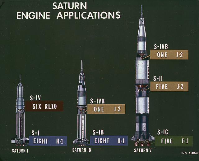
This image illustrates the basic differences between the three Saturn launch vehicles developed by the Marshall Space Flight Center. The Saturn I, consisted of two stages, the S-I (eight H-1 engines) and the S-IV (six RL-10 engines). The Saturn IB (center) also consisted of two stages, the S-IB (eight H-1 engines) and the S-IVB (one J-2 engine). The Saturn V consisted of three stages, the S-IC (five F-1 engines), the S-II (five J-2 engines), and the S-IVB (one J-2 engine).
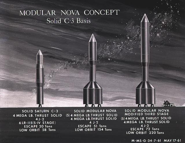
This artist's concept illustrates the Module Nova concept - Solid C-3 Basis. From 1960 to 1962, the Marshall Space Flight Center considered the Nova launch vehicle as a means to achieve a marned lunar landing with a direct flight to the Moon. Various configurations of the vehicle were examined. The latest configuration was a five-stage vehicle using eight F-1 engines in the first stage. Although the program was canceled after NASA planners selected the lunar/orbital rendezvous mode, the proposed F-1 engine would eventually be used in the Apollo Program to propel the first stage of the Saturn V launch vehicle.
This artist's concept illustrates the Module Nova concept - Solid C-3 Basis. From 1960 to 1962, the Marshall Space Flight Center considered the Nova launch vehicle as a means to achieve a marned lunar landing with a direct flight to the Moon. Various configurations of the vehicle were examined. The latest configuration was a five-stage vehicle using eight F-1 engines in the first stage. Although the program was canceled after NASA planners selected the lunar/orbital rendezvous mode, the proposed F-1 engine would eventually be used in the Apollo Program to propel the first stage of the Saturn V launch vehicle.
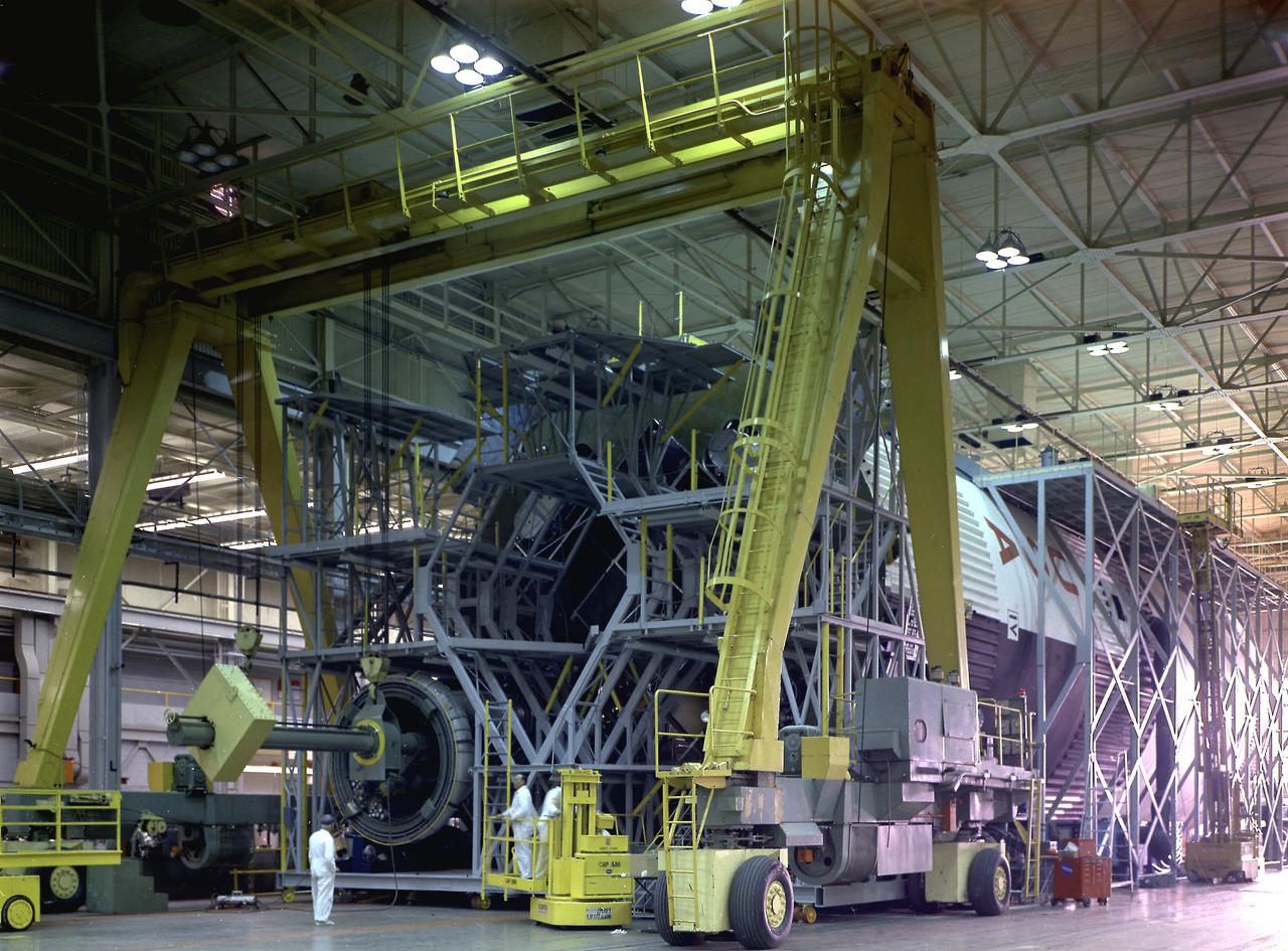
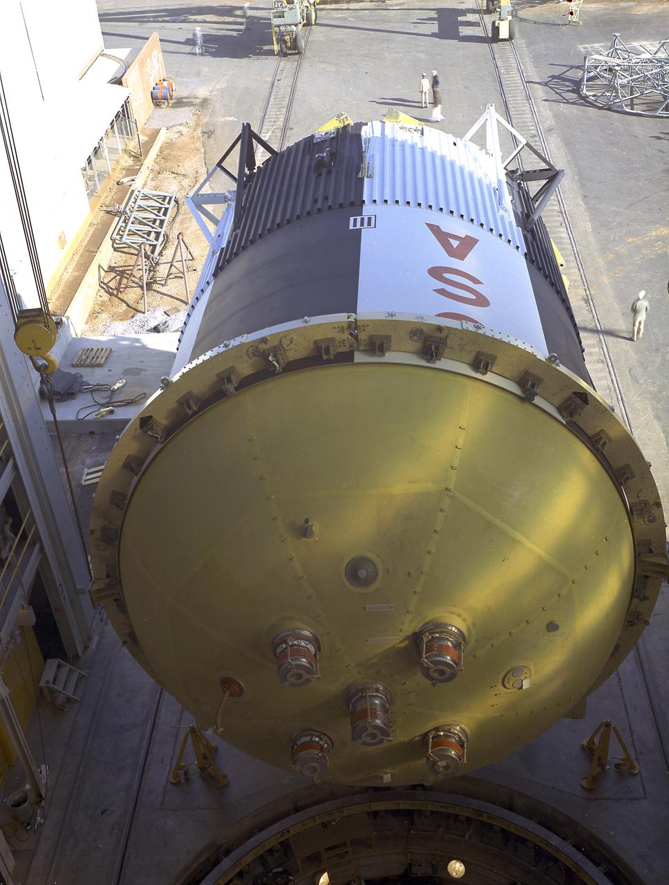
The fuel tank assembly of the Saturn V S-IC (first) stage supported with the aid of a C frame on the transporter was readied to be transported to the Marshall Space Flight Center, building 4705. The fuel tank carried kerosene (RP-1) as its fuel. The S-IC stage utilized five F-1 engines that used kerosene and liquid oxygen as propellant and each engine provided 1,500,000 pounds of thrust. This stage lifted the entire vehicle and Apollo spacecraft from the launch pad.
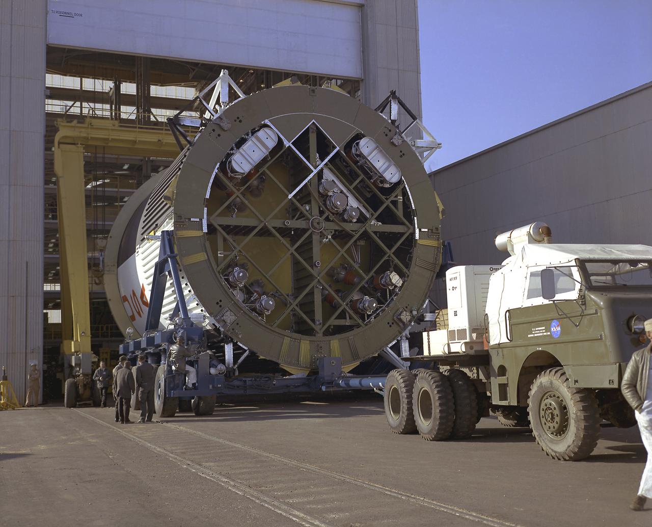
This photograph shows the fuel tank assembly for the Saturn V S-IC (first) stage being transported to the Marshall Space Flight Center, building 4705 for mating to the liquid oxygen (LOX) tank. The fuel tank carried kerosene (RP-1) as its fuel. The S-IC stage used five F-1 engines, that used kerosene and liquid oxygen as propellant and each engine provided 1,500,000 pounds of thrust. This stage lifted the entire vehicle and Apollo spacecraft from the launch pad.
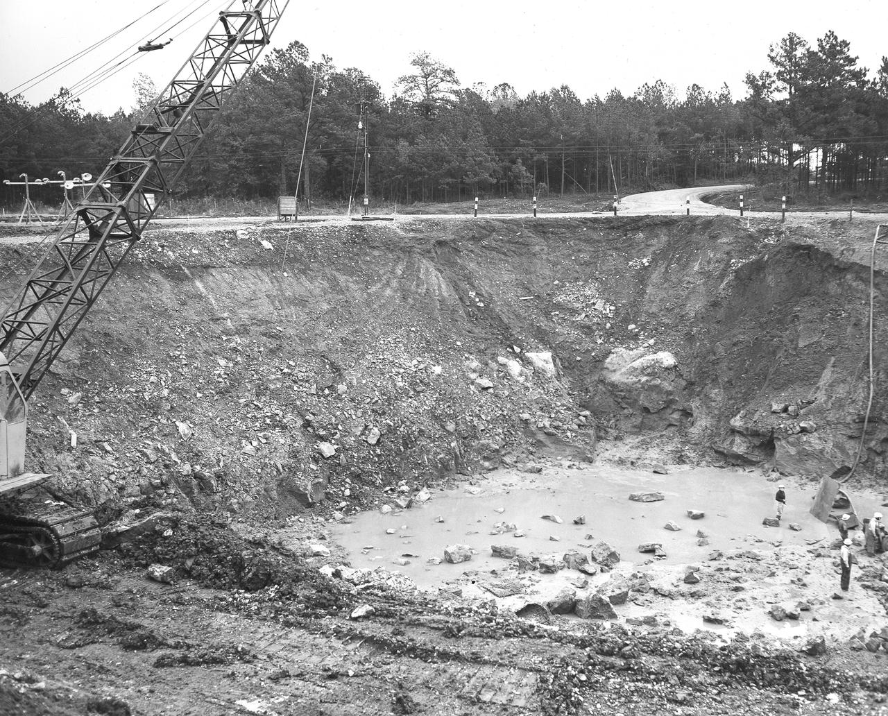
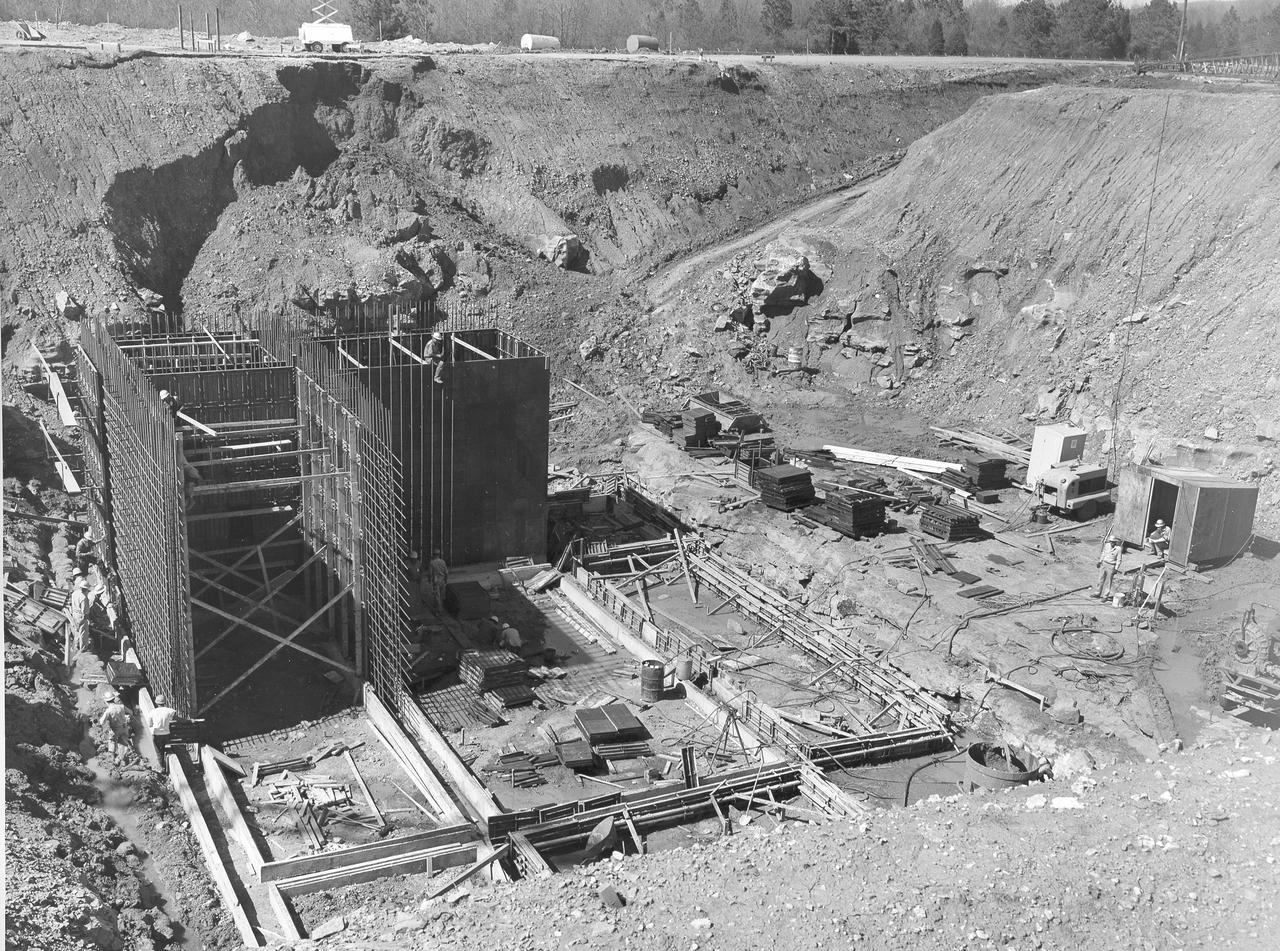
At its founding, the Marshall Space Flight Center (MSFC) inherited the Army’s Jupiter and Redstone test stands, but much larger facilities were needed for the giant stages of the Saturn V. From 1960 to 1964, the existing stands were remodeled and a sizable new test area was developed. The new comprehensive test complex for propulsion and structural dynamics was unique within the nation and the free world, and they remain so today because they were constructed with foresight to meet the future as well as on going needs. Construction of the S-IC Static test stand complex began in 1961 in the west test area of MSFC, and was completed in 1964. The S-IC static test stand was designed to develop and test the 138-ft long and 33-ft diameter Saturn V S-IC first stage, or booster stage, weighing in at 280,000 pounds. Required to hold down the brute force of a 7,500,000-pound thrust produced by 5 F-1 engines, the S-IC static test stand was designed and constructed with the strength of hundreds of tons of steel and 12,000,000 pounds of cement, planted down to bedrock 40 feet below ground level. The foundation walls, constructed with concrete and steel, are 4 feet thick. The base structure consists of four towers with 40-foot-thick walls extending upward 144 feet above ground level. The structure was topped by a crane with a 135-foot boom. With the boom in the upright position, the stand was given an overall height of 405 feet, placing it among the highest structures in Alabama at the time. In addition to the S-IC test stand, related facilities were built during this time. Built to the north of the massive S-IC test stand, was the F-1 Engine test stand. The F-1 test stand, a vertical engine firing test stand, 239 feet in elevation and 4,600 square feet in area at the base, was designed to assist in the development of the F-1 Engine. Capability was provided for static firing of 1.5 million pounds of thrust using liquid oxygen and kerosene. Like the S-IC stand, the foundation of the F-1 stand is keyed into the bedrock approximately 40 feet below grade. This photo, taken November 15, 1962, depicts the excavation process of the single engine F-1 stand site.
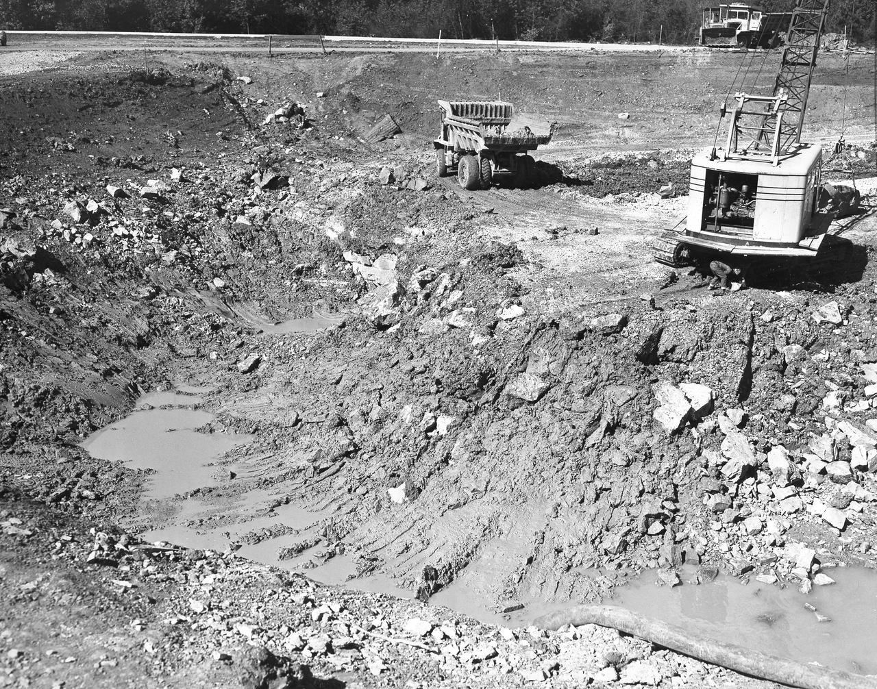
At its founding, the Marshall Space Flight Center (MSFC) inherited the Army’s Jupiter and Redstone test stands, but much larger facilities were needed for the giant stages of the Saturn V. From 1960 to 1964, the existing stands were remodeled and a sizable new test area was developed. The new comprehensive test complex for propulsion and structural dynamics was unique within the nation and the free world, and they remain so today because they were constructed with foresight to meet the future as well as on going needs. Construction of the S-IC Static test stand complex began in 1961 in the west test area of MSFC, and was completed in 1964. The S-IC static test stand was designed to develop and test the 138-ft long and 33-ft diameter Saturn V S-IC first stage, or booster stage, weighing in at 280,000 pounds. Required to hold down the brute force of a 7,500,000-pound thrust produced by 5 F-1 engines, the S-IC static test stand was designed and constructed with the strength of hundreds of tons of steel and 12,000,000 pounds of cement, planted down to bedrock 40 feet below ground level. The foundation walls, constructed with concrete and steel, are 4 feet thick. The base structure consists of four towers with 40-foot-thick walls extending upward 144 feet above ground level. The structure was topped by a crane with a 135-foot boom. With the boom in the upright position, the stand was given an overall height of 405 feet, placing it among the highest structures in Alabama at the time. In addition to the S-IC test stand, related facilities were built during this time. Built to the north of the massive S-IC test stand, was the F-1 Engine test stand. The F-1 test stand, a vertical engine firing test stand, 239 feet in elevation and 4,600 square feet in area at the base, was designed to assist in the development of the F-1 Engine. Capability was provided for static firing of 1.5 million pounds of thrust using liquid oxygen and kerosene. Like the S-IC stand, the foundation of the F-1 stand is keyed into the bedrock approximately 40 feet below grade. This photo, taken October 26, 1962, depicts the excavation process of the single engine F-1 stand.
Marshall Space Flight Center successfully conducted hydrostatic testing on the Saturn V S-IC (first) stage fuel tank. The first stage was powered by five F-1 engines, that used liquid oxygen and kerosene as its propellant.

THE GAS GENERATOR TO AN F-1 ENGINE, THE MOST POWERFUL ROCKET ENGINE EVER BUILT, IS TEST-FIRED AT NASA'S MARSHALL SPACE FLIGHT CENTER IN HUNTSVILLE, ALABAMA, ON SEPT. 3. ALTHOUGH THE ENGINE WAS ORIGINALLY BUILT TO POWER THE SATURN V ROCKETS DURING AMERICA'S MISSIONS TO THE MOON, THIS TEST ARTICLE HAD NEW PARTS CREATED USING ADDITIVE MANUFACTURING, OR 3-D PRINTING, TO TEST THE VIABILITY OF THE TECHNOLOGY FOR BUILDING NEW ENGINE DESIGNS.
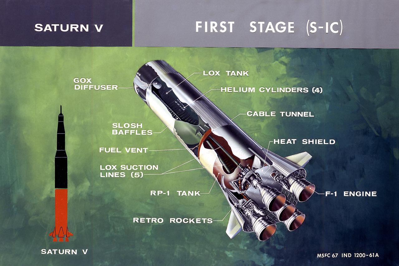
This illustration shows a cutaway drawing with callouts of the major components for the S-IC (first) stage of the Saturn V launch vehicle. The S-IC stage is 138 feet long and 33 feet in diameter, producing more than 7,500,000 pounds of thrust through five F-1 engines powered by liquid oxygen and kerosene. Four of the engines are mounted on an outer ring and gimball for control purposes. The fifth engine is rigidly mounted in the center. When ignited, the roar produced by the five engines equals the sound of 8,000,000 hi-fi sets.

THE GAS GENERATOR TO AN F-1 ENGINE, THE MOST POWERFUL ROCKET ENGINE EVER BUILT, IS TEST-FIRED AT NASA'S MARSHALL SPACE FLIGHT CENTER IN HUNTSVILLE, ALABAMA, ON SEPT. 3. ALTHOUGH THE ENGINE WAS ORIGINALLY BUILT TO POWER THE SATURN V ROCKETS DURING AMERICA'S MISSIONS TO THE MOON, THIS TEST ARTICLE HAD NEW PARTS CREATED USING ADDITIVE MANUFACTURING, OR 3-D PRINTING, TO TEST THE VIABILITY OF THE TECHNOLOGY FOR BUILDING NEW ENGINE DESIGNS.

THE GAS GENERATOR TO AN F-1 ENGINE, THE MOST POWERFUL ROCKET ENGINE EVER BUILT, IS TEST-FIRED AT NASA'S MARSHALL SPACE FLIGHT CENTER IN HUNTSVILLE, ALABAMA, ON SEPT. 3. ALTHOUGH THE ENGINE WAS ORIGINALLY BUILT TO POWER THE SATURN V ROCKETS DURING AMERICA'S MISSIONS TO THE MOON, THIS TEST ARTICLE HAD NEW PARTS CREATED USING ADDITIVE MANUFACTURING, OR 3-D PRINTING, TO TEST THE VIABILITY OF THE TECHNOLOGY FOR BUILDING NEW ENGINE DESIGNS.
This cutaway illustration shows the Saturn V S-IC (first) stage with detailed callouts of the components. The S-IC Stage is 138 feet long and 33 feet in diameter, producing 7,500,000 pounds of thrust through five F-1 engines that are powered by liquid oxygen and kerosene. Four of the engines are mounted on an outer ring and gimbal for control purposes. The fifth engine is rigidly mounted in the center. When ignited, the roar produced by the five engines equals the sound of 8,000,000 hi-fi sets.
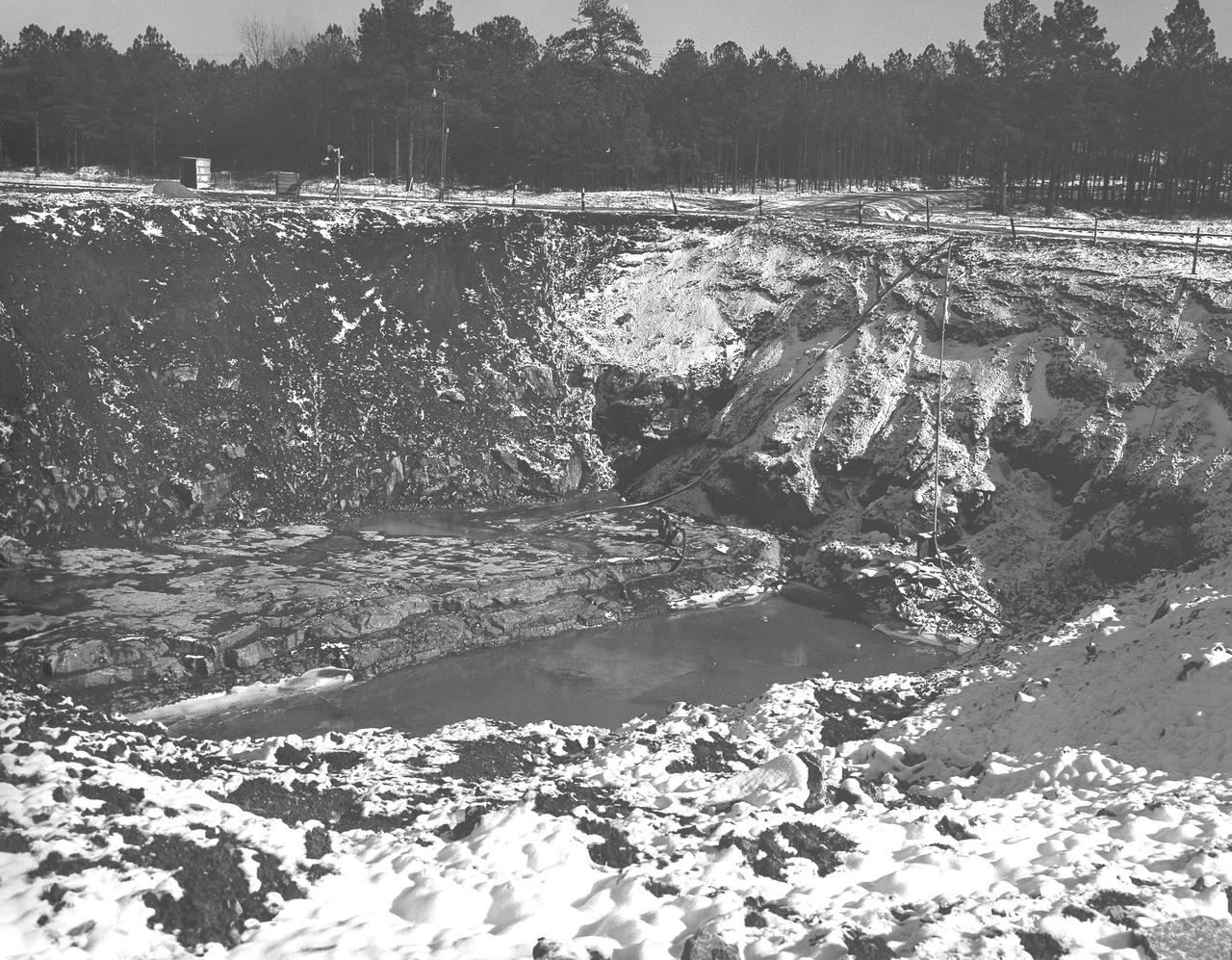
At its founding, the Marshall Space Flight Center (MSFC) inherited the Army’s Jupiter and Redstone test stands, but much larger facilities were needed for the giant stages of the Saturn V. From 1960 to 1964, the existing stands were remodeled and a sizable new test area was developed. The new comprehensive test complex for propulsion and structural dynamics was unique within the nation and the free world, and they remain so today because they were constructed with foresight to meet the future as well as on going needs. Construction of the S-IC Static test stand complex began in 1961 in the west test area of MSFC, and was completed in 1964. The S-IC static test stand was designed to develop and test the 138-ft long and 33-ft diameter Saturn V S-IC first stage, or booster stage, weighing in at 280,000 pounds. Required to hold down the brute force of a 7,500,000-pound thrust produced by 5 F-1 engines, the S-IC static test stand was designed and constructed with the strength of hundreds of tons of steel and 12,000,000 pounds of cement, planted down to bedrock 40 feet below ground level. The foundation walls, constructed with concrete and steel, are 4 feet thick. The base structure consists of four towers with 40-foot-thick walls extending upward 144 feet above ground level. The structure was topped by a crane with a 135-foot boom. With the boom in the upright position, the stand was given an overall height of 405 feet, placing it among the highest structures in Alabama at the time. In addition to the S-IC test stand, related facilities were constructed during this time frame. Built just north of the massive S-IC test stand was the F-1 Engine test stand. The F-1 test stand is a vertical engine firing test stand, 239 feet in elevation and 4,600 square feet in area at the base, and was designed to assist in the development of the F-1 Engine. Capability was provided for static firing of 1.5 million pounds of thrust using liquid oxygen and kerosene. Like the S-IC stand, the foundation of the F-1 stand is keyed into the bedrock approximately 40 feet below grade. This photo, taken January 14, 1963 depicts the F-1 test stand site with hoses pumping excess water from the site.
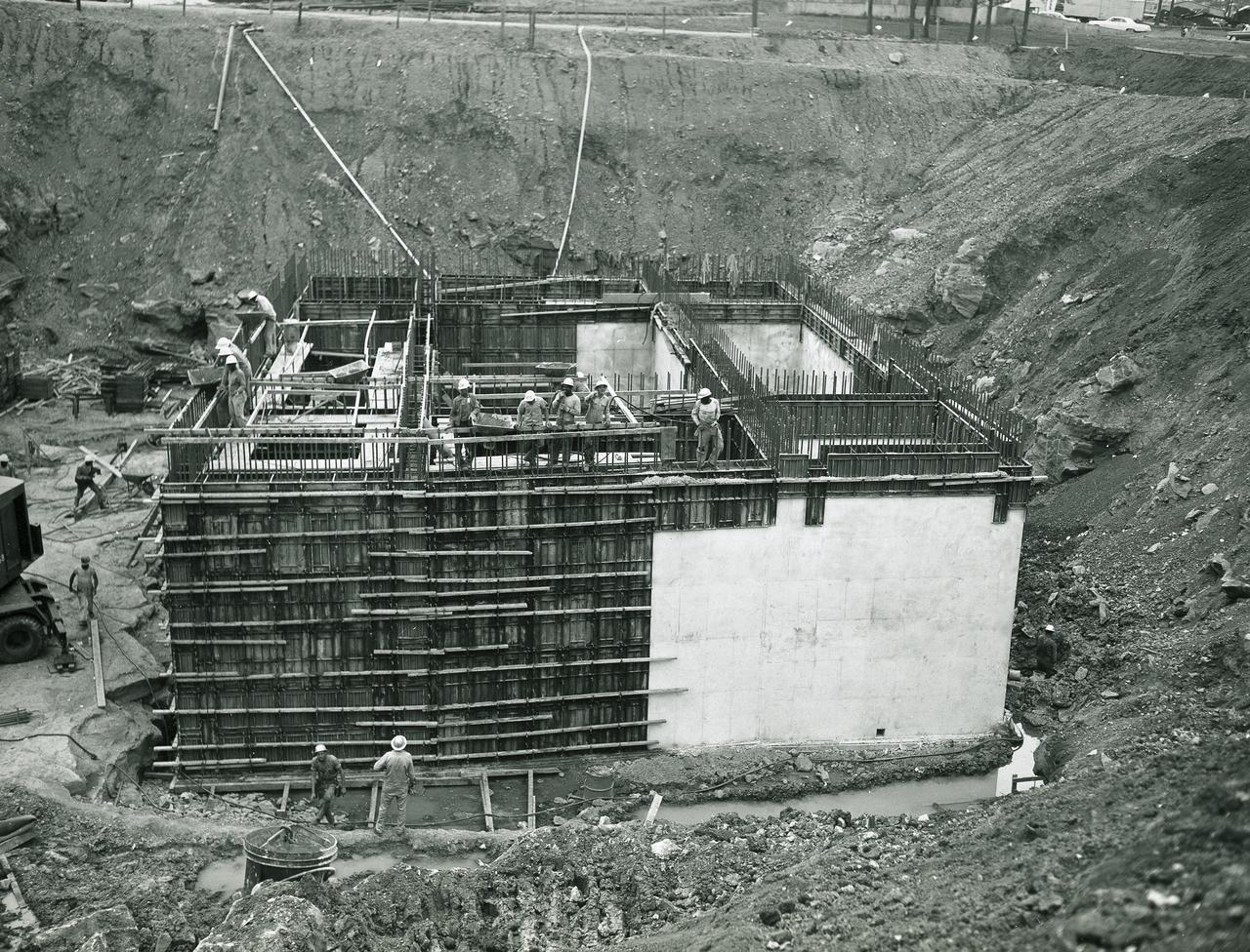
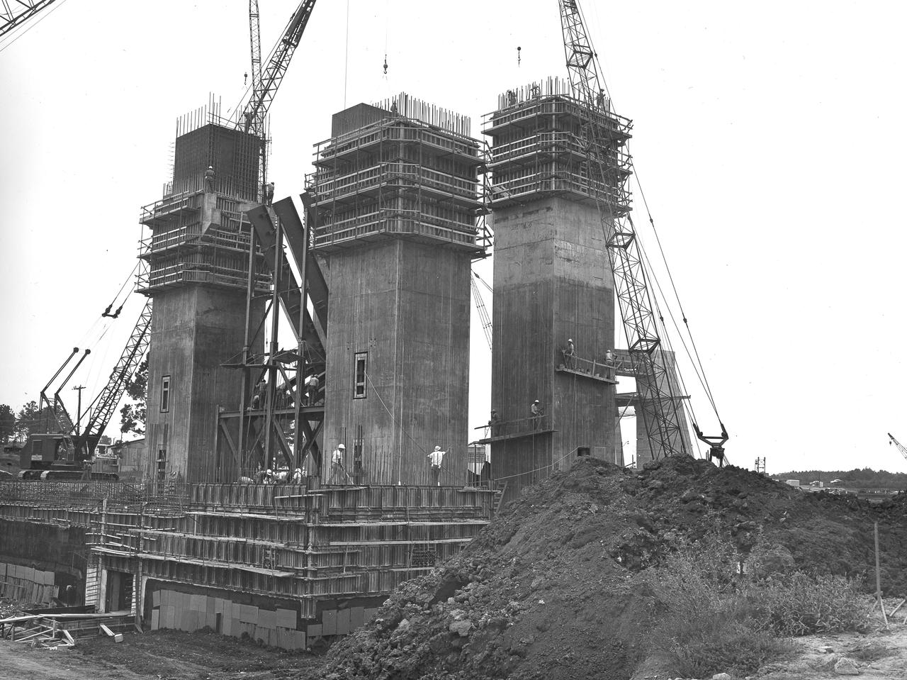
At its founding, the Marshall Space Flight Center (MSFC) inherited the Army’s Jupiter and Redstone test stands, but much larger facilities were needed for the giant stages of the Saturn V. From 1960 to 1964, the existing stands were remodeled and a sizable new test area was developed. The new comprehensive test complex for propulsion and structural dynamics was unique within the nation and the free world, and they remain so today because they were constructed with foresight to meet the future as well as on going needs. Construction of the S-IC Static test stand complex began in 1961 in the west test area of MSFC, and was completed in 1964. The S-IC static test stand was designed to develop and test the 138-ft long and 33-ft diameter Saturn V S-IC first stage, or booster stage, weighing in at 280,000 pounds. Required to hold down the brute force of a 7,500,000-pound thrust produced by 5 F-1 engines, the S-IC static test stand was designed and constructed with the strength of hundreds of tons of steel and 12,000,000 pounds of cement, planted down to bedrock 40 feet below ground level. The foundation walls, constructed with concrete and steel, are 4 feet thick. The base structure consists of four towers with 40-foot-thick walls extending upward 144 feet above ground level. The structure was topped by a crane with a 135-foot boom. With the boom in the upright position, the stand was given an overall height of 405 feet, placing it among the highest structures in Alabama at the time. In addition to the stand itself, related facilities were constructed during this time. North of the massive S-IC test stand, the F-1 Engine test stand was built. Designed to assist in the development of the F-1 Engine, the F-1 test stand is a vertical engine firing test stand, 239 feet in elevation and 4,600 square feet in area at the base. Capability was provided for static firing of 1.5 million pounds of thrust using liquid oxygen and kerosene. Like the S-IC stand, the foundation of the F-1 stand is keyed into the bedrock approximately 40 feet below grade. This photo depicts the construction of the F-1 test stand as of July 3, 1963. All four of its tower legs are well underway.
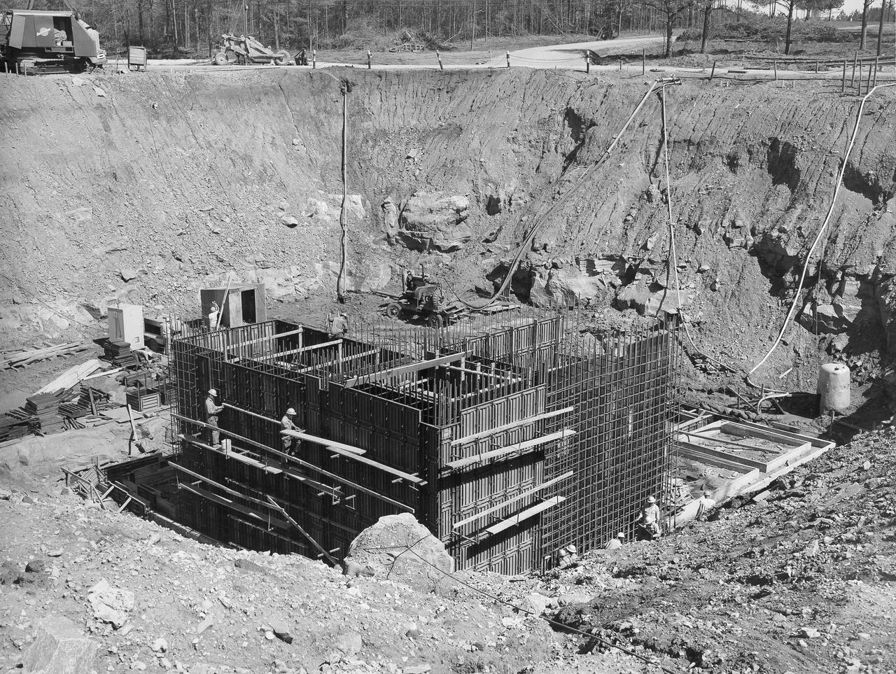
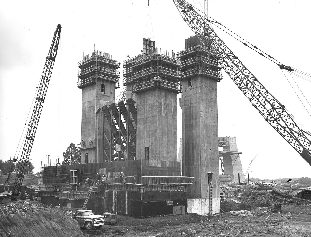
At its founding, the Marshall Space Flight Center (MSFC) inherited the Army’s Jupiter and Redstone test stands, but much larger facilities were needed for the giant stages of the Saturn V. From 1960 to 1964, the existing stands were remodeled and a sizable new test area was developed. The new comprehensive test complex for propulsion and structural dynamics was unique within the nation and the free world, and they remain so today because they were constructed with foresight to meet the future as well as on going needs. Construction of the S-IC Static test stand complex began in 1961 in the west test area of MSFC, and was completed in 1964. The S-IC static test stand was designed to develop and test the 138-ft long and 33-ft diameter Saturn V S-IC first stage, or booster stage, weighing in at 280,000 pounds. Required to hold down the brute force of a 7,500,000-pound thrust produced by 5 F-1 engines, the S-IC static test stand was designed and constructed with the strength of hundreds of tons of steel and 12,000,000 pounds of cement, planted down to bedrock 40 feet below ground level. The foundation walls, constructed with concrete and steel, are 4 feet thick. The base structure consists of four towers with 40-foot-thick walls extending upward 144 feet above ground level. The structure was topped by a crane with a 135-foot boom. With the boom in the upright position, the stand was given an overall height of 405 feet, placing it among the highest structures in Alabama at the time. In addition to the stand itself, related facilities were constructed during this time. North of the massive S-IC test stand, the F-1 Engine test stand was built. Designed to assist in the development of the F-1 Engine, the F-1 test stand is a vertical engine firing test stand, 239 feet in elevation and 4,600 square feet in area at the base. Capability was provided for static firing of 1.5 million pounds of thrust using liquid oxygen and kerosene. Like the S-IC stand, the foundation of the F-1 stand is keyed into the bedrock approximately 40 feet below grade. This photo depicts the construction of the F-1 test stand as of August 13, 1963. All four of its tower legs are well underway into the skyline.
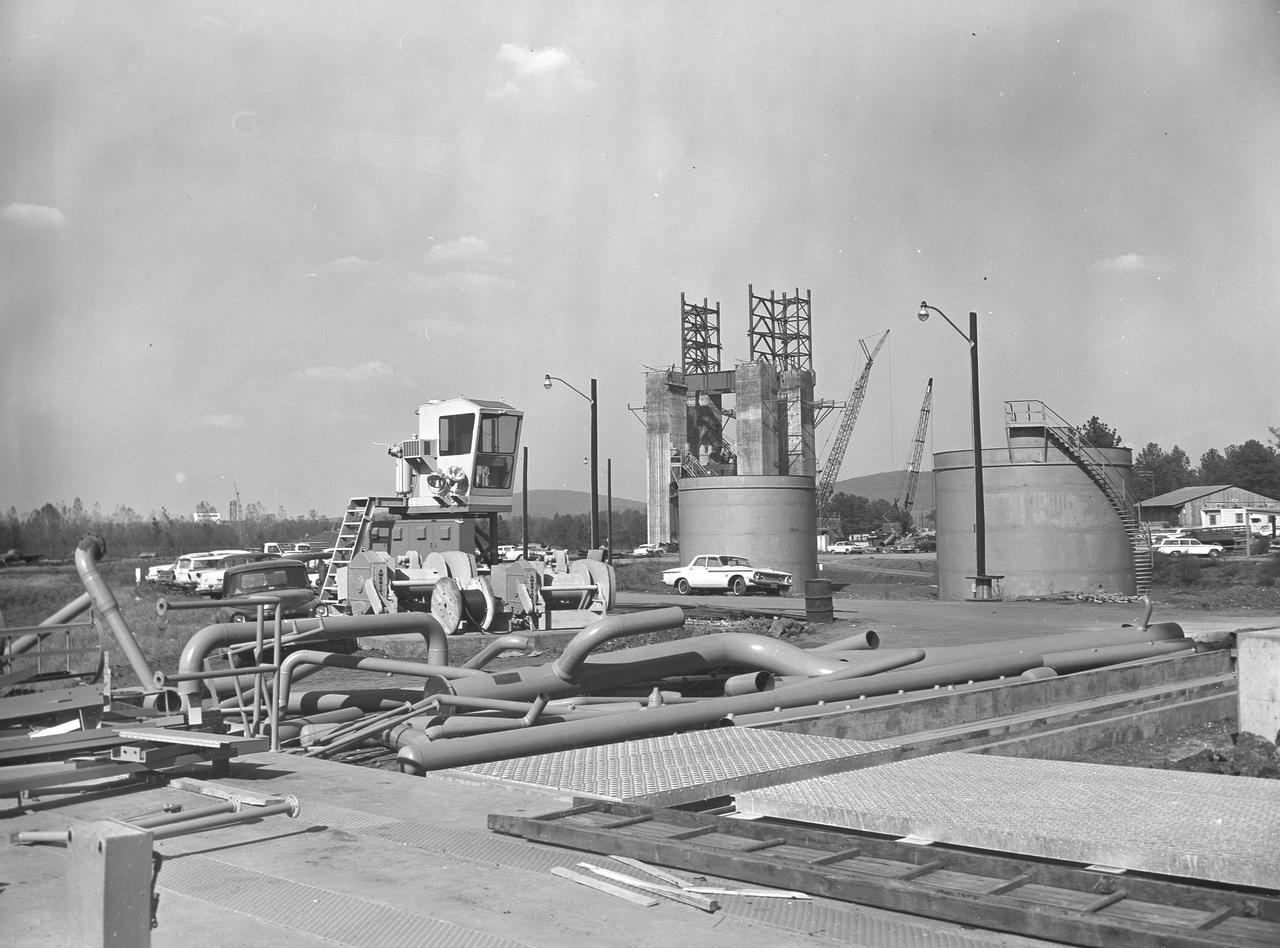
At its founding, the Marshall Space Flight Center (MSFC) inherited the Army’s Jupiter and Redstone test stands, but much larger facilities were needed for the giant stages of the Saturn V. From 1960 to 1964, the existing stands were remodeled and a sizable new test area was developed. The new comprehensive test complex for propulsion and structural dynamics was unique within the nation and the free world, and they remain so today because they were constructed with foresight to meet the future as well as on going needs. Construction of the S-IC Static test stand complex began in 1961 in the west test area of MSFC, and was completed in 1964. The S-IC static test stand was designed to develop and test the 138-ft long and 33-ft diameter Saturn V S-IC first stage, or booster stage, weighing in at 280,000 pounds. Required to hold down the brute force of a 7,500,000-pound thrust produced by 5 F-1 engines, the S-IC static test stand was designed and constructed with the strength of hundreds of tons of steel and 12,000,000 pounds of cement, planted down to bedrock 40 feet below ground level. The foundation walls, constructed with concrete and steel, are 4 feet thick. The base structure consists of four towers with 40-foot-thick walls extending upward 144 feet above ground level. The structure was topped by a crane with a 135-foot boom. With the boom in the upright position, the stand was given an overall height of 405 feet, placing it among the highest structures in Alabama at the time. In addition to the stand itself, related facilities were constructed during this time. Northeast of the massive S-IC test stand, the F-1 Engine test stand was built. The F-1 test stand is a vertical engine firing test stand, 239 feet in elevation and 4,600 square feet in area at the base, and was designed to assist in the development of the F-1 Engine. Capability was provided for static firing of 1.5 million pounds of thrust using liquid oxygen and kerosene. Like the S-IC stand, the foundation of the F-1 stand is keyed into the bedrock approximately 40 feet below grade. This photo depicts the fuel tanks that housed kerosene and just beyond those is the F-1 test stand.
At its founding, the Marshall Space Flight Center (MSFC) inherited the Army’s Jupiter and Redstone test stands, but much larger facilities were needed for the giant stages of the Saturn V. From 1960 to 1964, the existing stands were remodeled and a sizable new test area was developed. The new comprehensive test complex for propulsion and structural dynamics was unique within the nation and the free world, and they remain so today because they were constructed with foresight to meet the future as well as on going needs. Construction of the S-IC Static test stand complex began in 1961 in the west test area of MSFC, and was completed in 1964. The S-IC static test stand was designed to develop and test the 138-ft long and 33-ft diameter Saturn V S-IC first stage, or booster stage, weighing in at 280,000 pounds. Required to hold down the brute force of a 7,500,000-pound thrust produced by 5 F-1 engines, the S-IC static test stand was designed and constructed with the strength of hundreds of tons of steel and 12,000,000 pounds of cement, planted down to bedrock 40 feet below ground level. The foundation walls, constructed with concrete and steel, are 4 feet thick. The base structure consists of four towers with 40-foot-thick walls extending upward 144 feet above ground level. The structure was topped by a crane with a 135-foot boom. With the boom in the upright position, the stand was given an overall height of 405 feet, placing it among the highest structures in Alabama at the time. In addition to the stand itself, related facilities were constructed during this time. North of the massive S-IC test stand, the F-1 Engine test stand was built. Designed to assist in the development of the F-1 Engine, the F-1 test stand is a vertical engine firing test stand, 239 feet in elevation and 4,600 square feet in area at the base. Capability was provided for static firing of 1.5 million pounds of thrust using liquid oxygen and kerosene. Like the S-IC stand, the foundation of the F-1 stand is keyed into the bedrock approximately 40 feet below grade. This photo depicts the construction of the F-1 test stand as of September 30, 1963.
At its founding, the Marshall Space Flight Center (MSFC) inherited the Army’s Jupiter and Redstone test stands, but much larger facilities were needed for the giant stages of the Saturn V. From 1960 to 1964, the existing stands were remodeled and a sizable new test area was developed. The new comprehensive test complex for propulsion and structural dynamics was unique within the nation and the free world, and they remain so today because they were constructed with foresight to meet the future as well as on going needs. Construction of the S-IC Static test stand complex began in 1961 in the west test area of MSFC, and was completed in 1964. The S-IC static test stand was designed to develop and test the 138-ft long and 33-ft diameter Saturn V S-IC first stage, or booster stage, weighing in at 280,000 pounds. Required to hold down the brute force of a 7,500,000-pound thrust produced by 5 F-1 engines, the S-IC static test stand was designed and constructed with the strength of hundreds of tons of steel and 12,000,000 pounds of cement, planted down to bedrock 40 feet below ground level. The foundation walls, constructed with concrete and steel, are 4 feet thick. The base structure consists of four towers with 40-foot-thick walls extending upward 144 feet above ground level. The structure was topped by a crane with a 135-foot boom. With the boom in the upright position, the stand was given an overall height of 405 feet, placing it among the highest structures in Alabama at the time. In addition to the stand itself, related facilities were constructed during this time. North of the massive S-IC test stand, the F-1 Engine test stand was built. Designed to assist in the development of the F-1 Engine, the F-1 test stand is a vertical engine firing test stand, 239 feet in elevation and 4,600 square feet in area at the base. Capability was provided for static firing of 1.5 million pounds of thrust using liquid oxygen and kerosene. Like the S-IC stand, the foundation of the F-1 stand is keyed into the bedrock approximately 40 feet below grade. This photo depicts the construction of the F-1 test stand as of September 5, 1963.
At its founding, the Marshall Space Flight Center (MSFC) inherited the Army’s Jupiter and Redstone test stands, but much larger facilities were needed for the giant stages of the Saturn V. From 1960 to 1964, the existing stands were remodeled and a sizable new test area was developed. The new comprehensive test complex for propulsion and structural dynamics was unique within the nation and the free world, and they remain so today because they were constructed with foresight to meet the future as well as on going needs. Construction of the S-IC Static test stand complex began in 1961 in the west test area of MSFC, and was completed in 1964. The S-IC static test stand was designed to develop and test the 138-ft long and 33-ft diameter Saturn V S-IC first stage, or booster stage, weighing in at 280,000 pounds. Required to hold down the brute force of a 7,500,000-pound thrust produced by 5 F-1 engines, the S-IC static test stand was designed and constructed with the strength of hundreds of tons of steel and 12,000,000 pounds of cement, planted down to bedrock 40 feet below ground level. The foundation walls, constructed with concrete and steel, are 4 feet thick. The base structure consists of four towers with 40-foot-thick walls extending upward 144 feet above ground level. The structure was topped by a crane with a 135-foot boom. With the boom in the upright position, the stand was given an overall height of 405 feet, placing it among the highest structures in Alabama at the time. In addition to the stand itself, related facilities were constructed during this time. North of the massive S-IC test stand, the F-1 Engine test stand was built. Designed to assist in the development of the F-1 Engine, the F-1 test stand is a vertical engine firing test stand, 239 feet in elevation and 4,600 square feet in area at the base. Capability was provided for static firing of 1.5 million pounds of thrust using liquid oxygen and kerosene. Like the S-IC stand, the foundation of the F-1 stand is keyed into the bedrock approximately 40 feet below grade. This photo depicts the construction of the F-1 test stand as of June 24, 1963. Two if its four tower legs are underway.
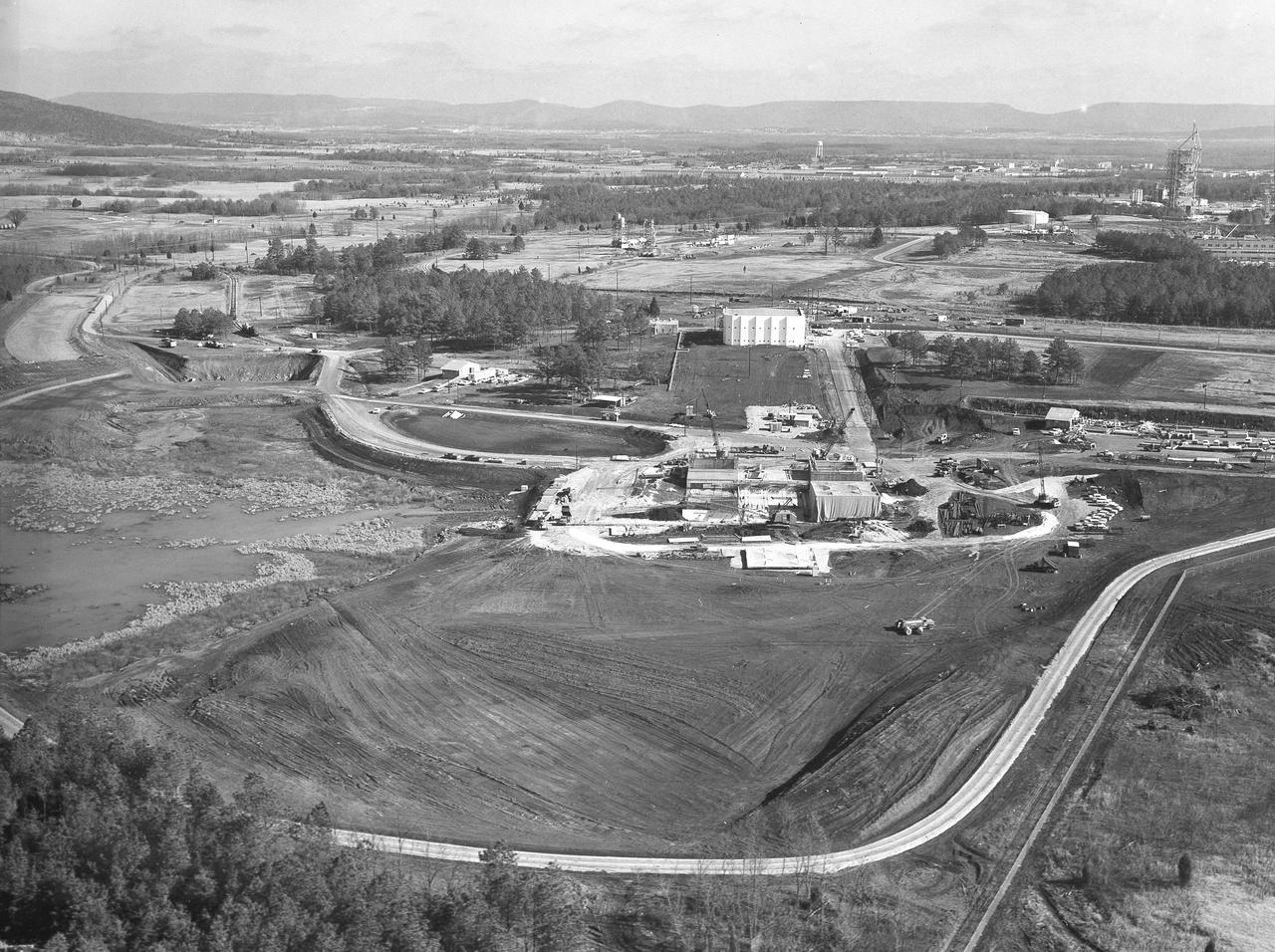
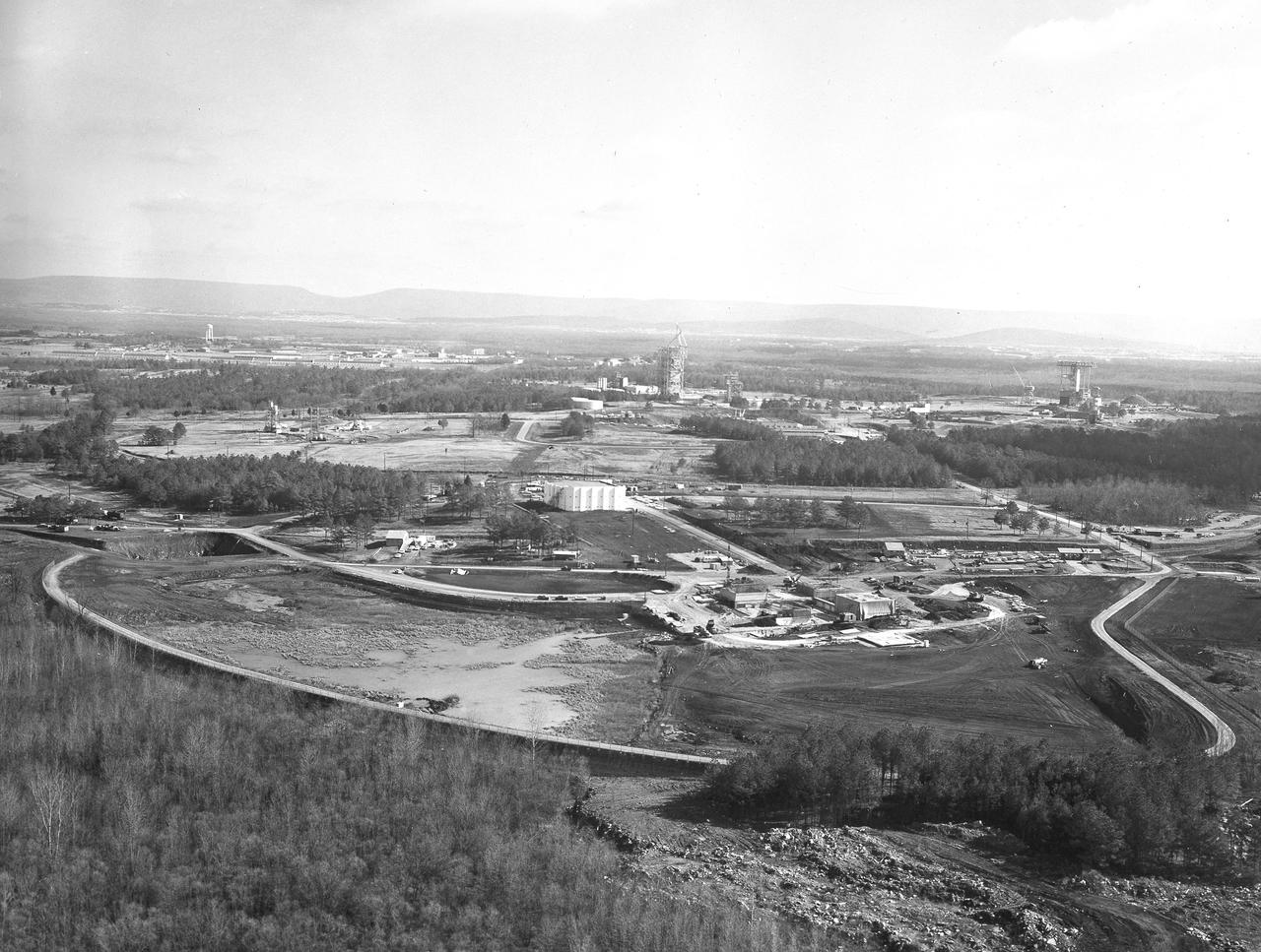
At its founding, the Marshall Space Flight Center (MSFC) inherited the Army’s Jupiter and Redstone test stands, but much larger facilities were needed for the giant stages of the Saturn V. From 1960 to 1964, the existing stands were remodeled and a sizable new test area was developed. The new comprehensive test complex for propulsion and structural dynamics was unique within the nation and the free world, and they remain so today because they were constructed with foresight to meet the future as well as on going needs. Construction of the S-IC Static test stand complex began in 1961 in the west test area of MSFC, and was completed in 1964. The S-IC static test stand was designed to develop and test the 138-ft long and 33-ft diameter Saturn V S-IC first stage, or booster stage, weighing in at 280,000 pounds. Required to hold down the brute force of a 7,500,000-pound thrust produced by 5 F-1 engines, the S-IC static test stand was designed and constructed with the strength of hundreds of tons of steel and 12,000,000 pounds of cement, planted down to bedrock 40 feet below ground level. The foundation walls, constructed with concrete and steel, are 4 feet thick. The base structure consists of four towers with 40-foot-thick walls extending upward 144 feet above ground level. The structure was topped by a crane with a 135-foot boom. With the boom in the upright position, the stand was given an overall height of 405 feet, placing it among the highest structures in Alabama at the time. In addition to the stand itself, related facilities were constructed during this time. Built directly east of the test stand was the Block House, which served as the control center for the test stand. The two were connected by a narrow access tunnel which housed the cables for the controls. The F-1 Engine test stand was built north of the massive S-IC test stand. The F-1 test stand is a vertical engine firing test stand, 239 feet in elevation and 4,600 square feet in area at the base, and was designed to assist in the development of the F-1 Engine. Capability is provided for static firing of 1.5 million pounds of thrust using liquid oxygen and kerosene. Like the S-IC stand, the foundation of the F-1 stand is keyed into the bedrock approximately 40 feet below grade. This aerial photograph, taken January 15, 1963, gives a close overall view of the newly developed test complex. Depicted in the forefront center is the S-IC test stand with towers prominent, the Block House is seen in the center just above the S-IC test stand, and the large hole to the left, located midway between the two is the F-1 test stand site.
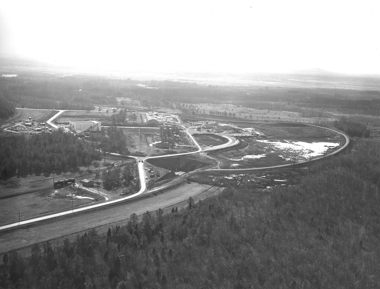
At its founding, the Marshall Space Flight Center (MSFC) inherited the Army’s Jupiter and Redstone test stands, but much larger facilities were needed for the giant stages of the Saturn V. From 1960 to 1964, the existing stands were remodeled and a sizable new test area was developed. The new comprehensive test complex for propulsion and structural dynamics was unique within the nation and the free world, and they remain so today because they were constructed with foresight to meet the future as well as on going needs. Construction of the S-IC Static test stand complex began in 1961 in the west test area of MSFC, and was completed in 1964. The S-IC static test stand was designed to develop and test the 138-ft long and 33-ft diameter Saturn V S-IC first stage, or booster stage, weighing in at 280,000 pounds. Required to hold down the brute force of a 7,500,000-pound thrust produced by 5 F-1 engines, the S-IC static test stand was designed and constructed with the strength of hundreds of tons of steel and 12,000,000 pounds of cement, planted down to bedrock 40 feet below ground level. The foundation walls, constructed with concrete and steel, are 4 feet thick. The base structure consists of four towers with 40-foot-thick walls extending upward 144 feet above ground level. The structure was topped by a crane with a 135-foot boom. With the boom in the upright position, the stand was given an overall height of 405 feet, placing it among the highest structures in Alabama at the time. In addition to the stand itself, related facilities were constructed during this time. Built directly east of the test stand was the Block House, which served as the control center for the test stand. The two were connected by a narrow access tunnel which housed the cables for the controls. The F-1 Engine test stand was built north of the massive S-IC test stand. The F-1 test stand is a vertical engine firing test stand, 239 feet in elevation and 4,600 square feet in area at the base, and was designed to assist in the development of the F-1 Engine. Capability is provided for static firing of 1.5 million pounds of thrust using liquid oxygen and kerosene. Like the S-IC stand, the foundation of the F-1 stand is keyed into the bedrock approximately 40 feet below grade. Looking North, this aerial taken January 15, 1963, gives a closer view of the deep hole for the F-1 test stand site in the forefront. The S-IC test stand with towers prominent is to the right of center, and the Block House is seen left of center.
At its founding, the Marshall Space Flight Center (MSFC) inherited the Army’s Jupiter and Redstone test stands, but much larger facilities were needed for the giant stages of the Saturn V. From 1960 to 1964, the existing stands were remodeled and a sizable new test area was developed. The new comprehensive test complex for propulsion and structural dynamics was unique within the nation and the free world, and they remain so today because they were constructed with foresight to meet the future as well as on going needs. Construction of the S-IC Static test stand complex began in 1961 in the west test area of MSFC, and was completed in 1964. The S-IC static test stand was designed to develop and test the 138-ft long and 33-ft diameter Saturn V S-IC first stage, or booster stage, weighing in at 280,000 pounds. Required to hold down the brute force of a 7,500,000-pound thrust produced by 5 F-1 engines, the S-IC static test stand was designed and constructed with the strength of hundreds of tons of steel and 12,000,000 pounds of cement, planted down to bedrock 40 feet below ground level. The foundation walls, constructed with concrete and steel, are 4 feet thick. The base structure consists of four towers with 40-foot-thick walls extending upward 144 feet above ground level. The structure was topped by a crane with a 135-foot boom. With the boom in the upright position, the stand was given an overall height of 405 feet, placing it among the highest structures in Alabama at the time. In addition to the stand itself, related facilities were constructed during this time. Built directly east of the test stand was the Block House, which served as the control center for the test stand. The two were connected by a narrow access tunnel which housed the cables for the controls. The F-1 Engine test stand was built north of the massive S-IC test stand. The F-1 test stand is a vertical engine firing test stand, 239 feet in elevation and 4,600 square feet in area at the base, and was designed to assist in the development of the F-1 Engine. Capability is provided for static firing of 1.5 million pounds of thrust using liquid oxygen and kerosene. Like the S-IC stand, the foundation of the F-1 stand is keyed into the bedrock approximately 40 feet below grade. This aerial photograph, taken January 15, 1963 gives an overall view of the construction progress of the newly developed test complex. The large white building located in the center is the Block House. Just below and to the right of it is the S-IC test stand. The large hole to the left of the S-IC stand is the F-1 test stand site.
This image illustrates technicians working on a full scale engineering mock-up of a Saturn V S-IC stage thrust structure nearing completion at the Manufacturing Engineering Laboratory at Marshall Space Flight Center. The booster, 33 feet in diameter and 138 feet long, was powered by five F-1 engines that provided 7,500,000 pounds of thrust to start the monstrous vehicle on its journey into space.
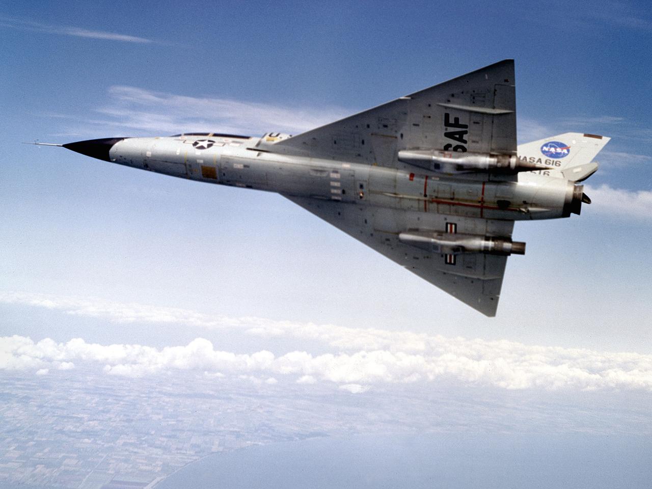
A Convair F-106B Delta Dart rolls to the right to reveal the two research engines installed under its wings by the National Aeronautics and Space Administration (NASA) Lewis Research Center. Lewis acquired the aircraft in October of 1966 to study inlet and nozzle designs for the supersonic transport engine program. Two General Electric J85 engines were mounted beneath the F-106B’s wings and operated from Mach 1 to 1.5. The right wing always carried reference nozzle for which the performance was known. Six supersonic nozzle variations and two inlets were tested on the left engine. The designs had already been studied in the Lewis wind tunnels, but those tests were limited by shock waves in the tunnels. Most F-106B flights were flown in a 200-mile path over the lake between Buffalo and Sandusky, known as the Lake Erie Corridor. The 1100-mile-per-hour flight took only 11 minutes at an altitude of 30,000 feet. The aircraft almost always returned with a depleted fuel supply so a Visual Flight Rules operation was required. Following the crash of another jet fighter at Lewis in July 1969, the F-106s were stationed at Selfridge Air Force Base in Michigan. NASA pilots flew transport planes each morning to the base before commencing the F-106B missions. After the supersonic transport program was cancelled, the F-106B was used as a test bed for additional engine exhaust nozzle configurations. The F-106B was also used to test inlet configurations for the noise reduction program.
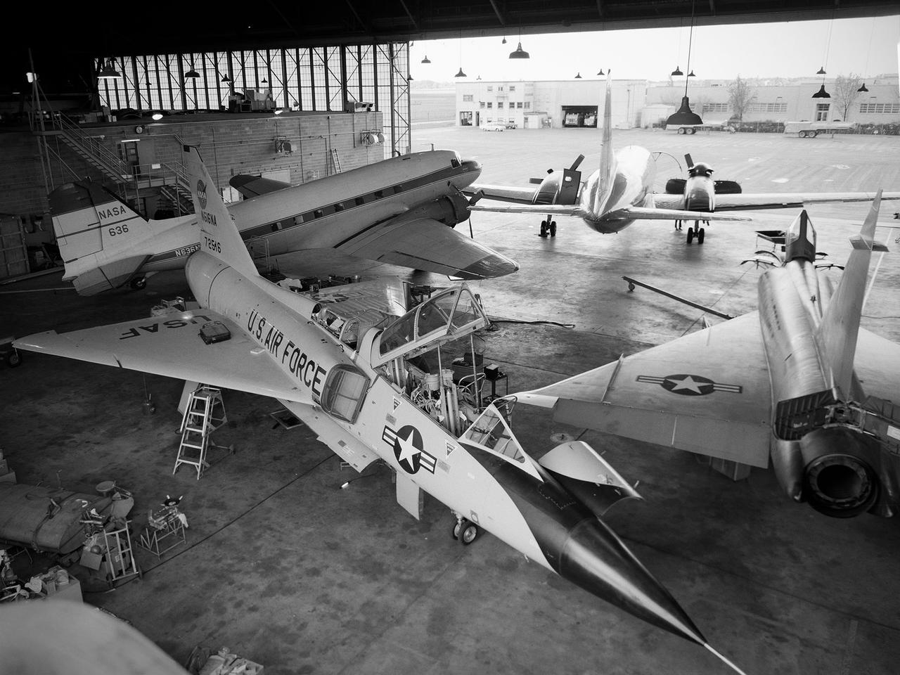
Several aircraft parked inside the Flight Research Building, or hangar, at the National Aeronautics and Space Administration (NASA) Lewis Research Center in Cleveland, Ohio. A Convair F-106B Delta Dart is in the foreground, a Convair F-102A Delta Dagger is to the right, a Douglas DC-3 is in the back to left, and a Convair T-29 is in background. Lewis’ Martin B-57B Canberra is not seen in this photograph. The F-102A had just been acquired by Lewis to serve as a chase plane for the F-106B. The Lewis team removed the weapons system and 700 pounds of wire from the F-106B when it was acquired on October 20, 1966. The staff cut holes in the wings and modified the elevons to mount the test nacelles. A 228-gallon fuel tank was installed in the missile bay, and the existing wing tanks were used for instrumentation. This photograph contains a rare view of the Block House, seen to the left of the aircraft. Lewis acquired three large developmental programs in 1962—the Centaur and Agena rockets and the M-1 engine. The center was short on office space at the time, and its flight research program was temporarily on the wane. Lewis management decided to construct a large cinderblock structure inside one half of the hangar to house the new personnel. This structure was used until 1965 when the new Developmental Engineering Building was built. The Block House was eventually torn down in 1973.
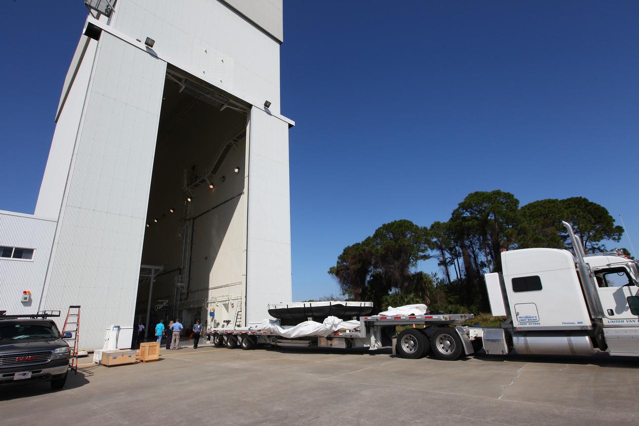
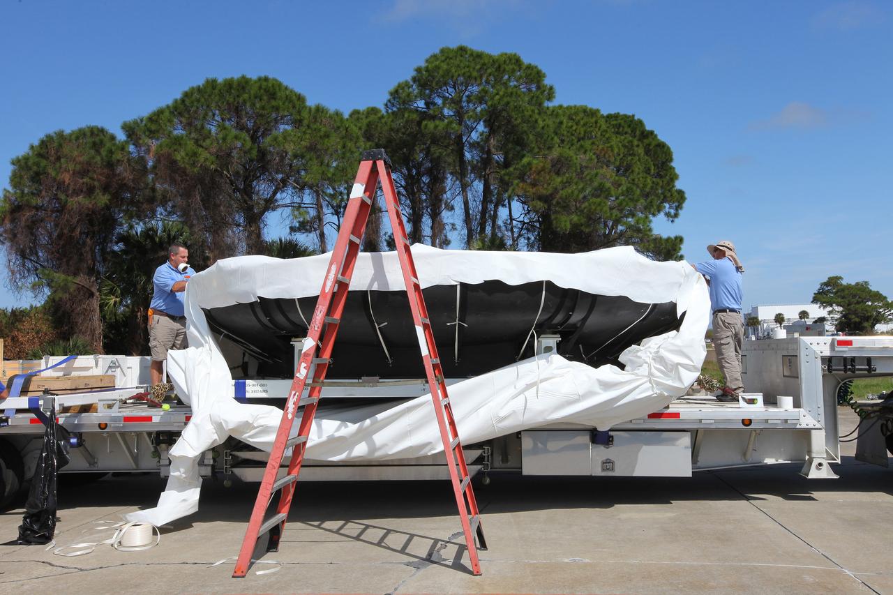
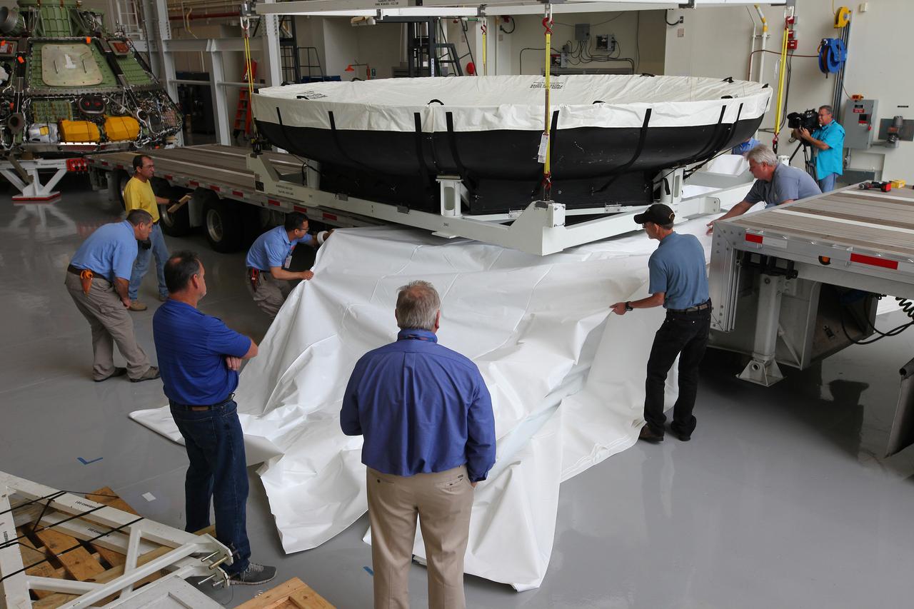
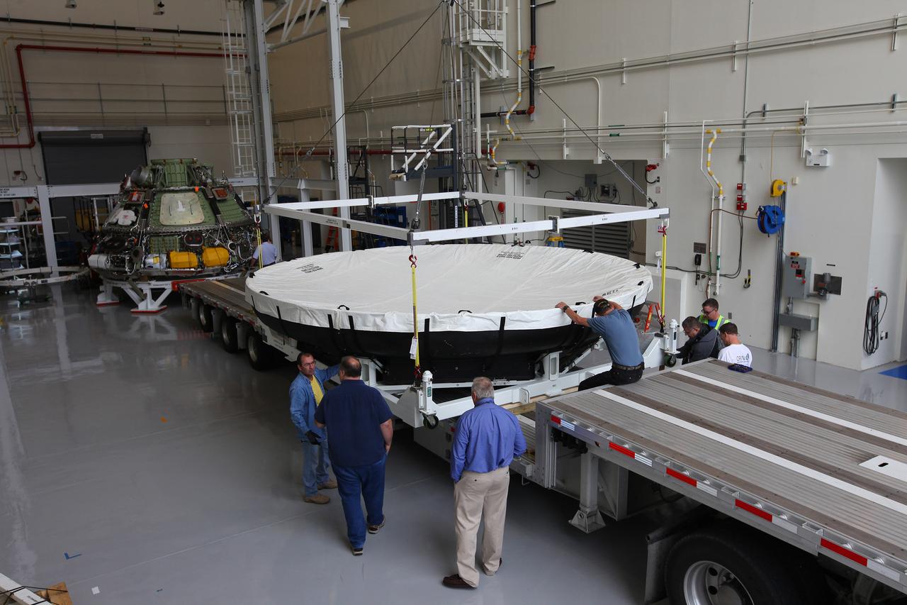
Engineers at Kennedy Space Center prepare the Orion heat shield for transport to Marshall Space Flight Center for testing on March 2, 2015. The heat shield flew on Orion's Exploration Flight Test-1 (EFT-1) in December 2014, protecting the spacecraft from 4000 degree F temperatures during reentry. Part of Batch image transfer from Flickr.
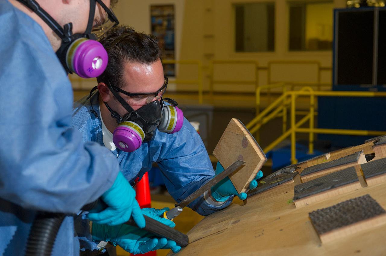
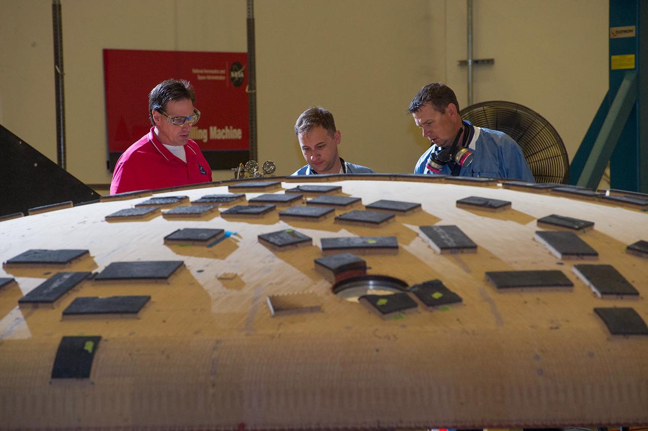
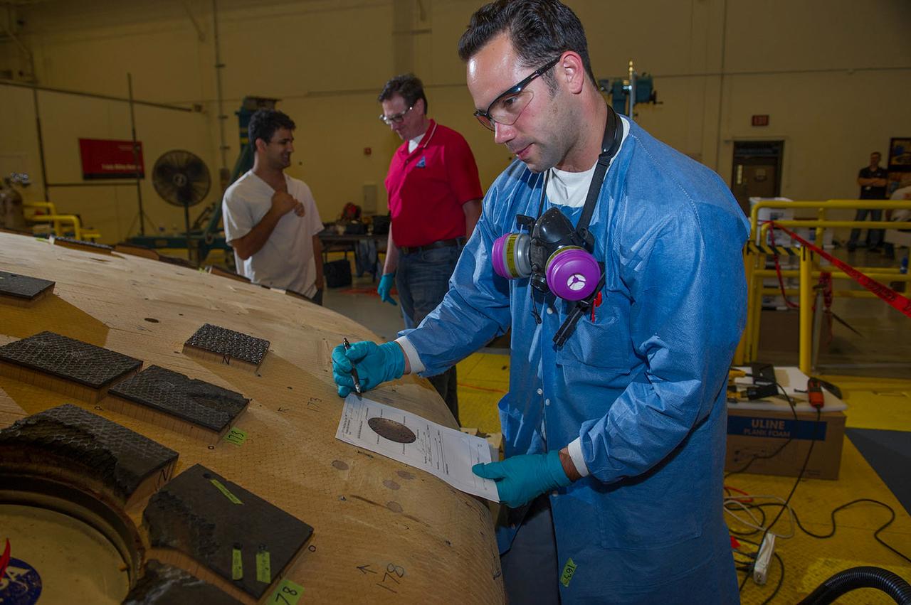
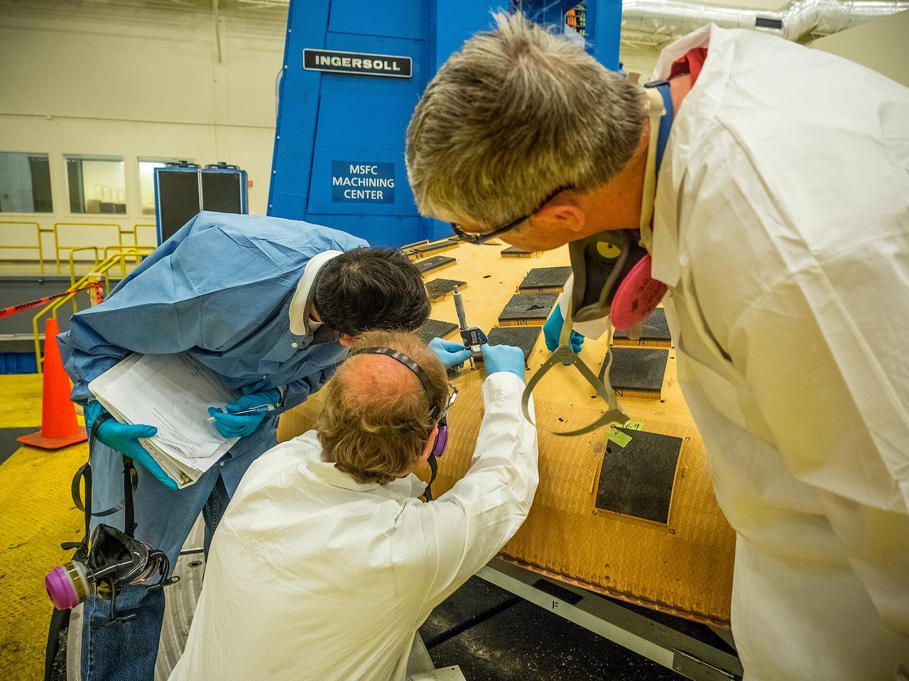
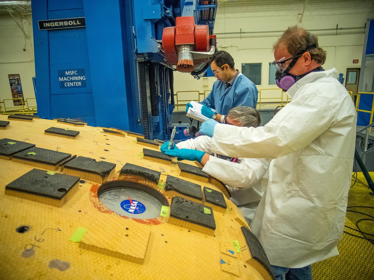
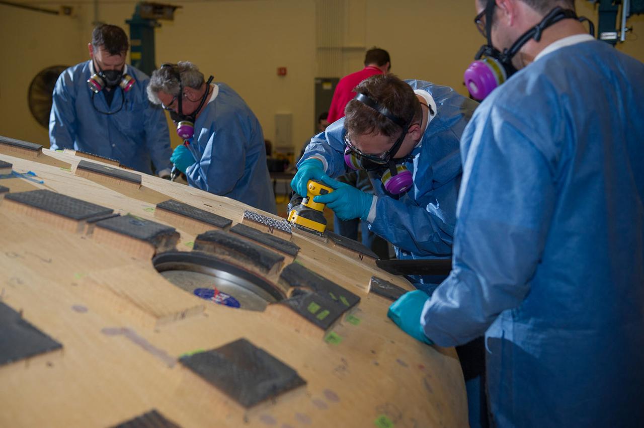
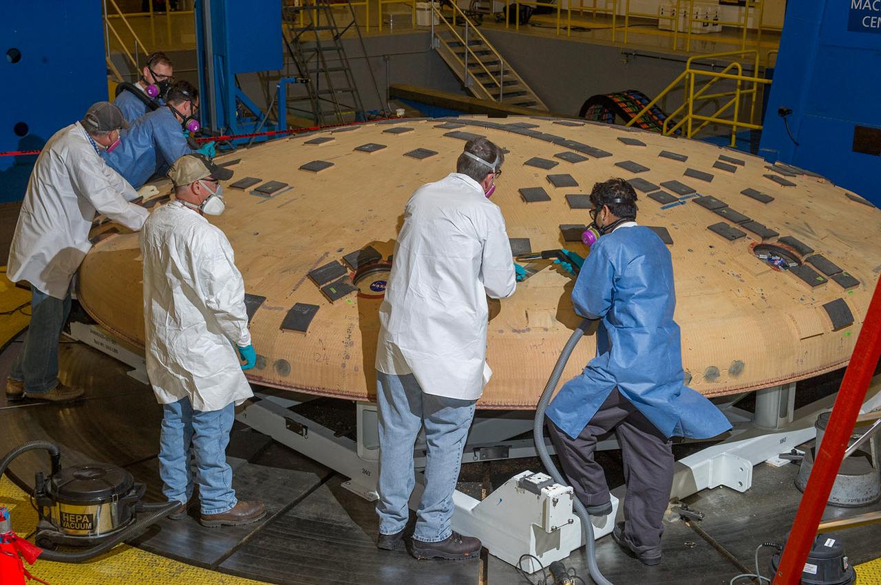
Engineers from NASA's Ames Research Center at Moffett Field, California, and Marshall Space Flight Center in Huntsville, Alabama, remove samples on May 4, 2015, from Orion's heat shield which flew on Exploration Flight Test-1 (EFT-1) in 2014. The heat shield protected the spacecraft from temperatures reaching 4000 degrees F. Part of Batch image transfer from Flickr.
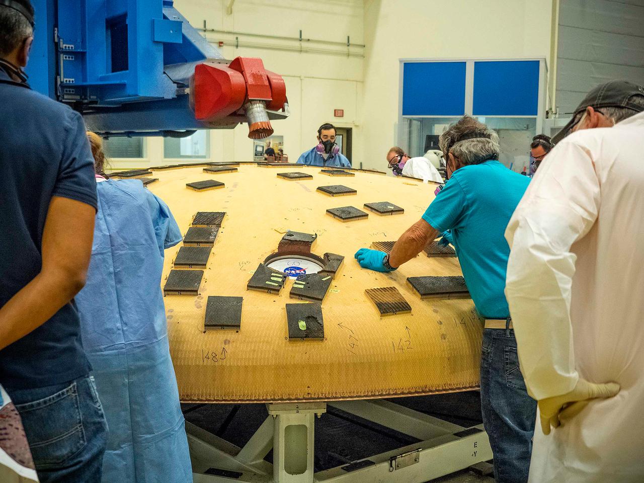
Engineers from NASA's Ames Research Center at Moffett Field, California, and Marshall Space Flight Center in Huntsville, Alabama, remove samples on May 4, 2015, from Orion's heat shield which flew on Exploration Flight Test-1 (EFT-1) in 2014. The heat shield protected the spacecraft from temperatures reaching 4000 degrees F. Part of Batch image transfer from Flickr.
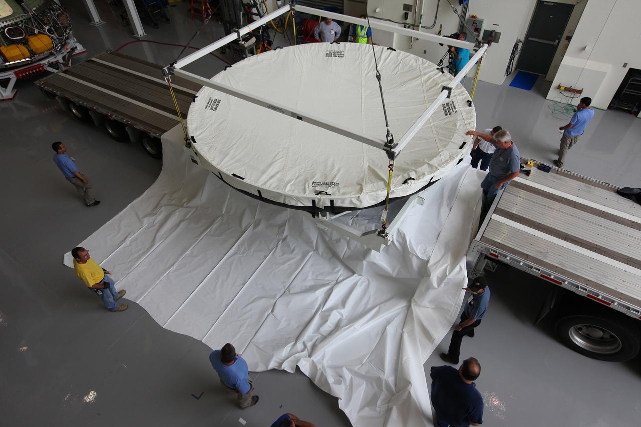
Engineers at Kennedy Space Center prepare the Orion heat shield for transport to Marshall Space Flight Center for testing on March 2, 2015. The heat shield flew on Orion's Exploration Flight Test-1 (EFT-1) in December 2014, protecting the spacecraft from 4000 degree F temperatures during reentry. Part of Batch image transfer from Flickr.
Engineers from NASA's Ames Research Center at Moffett Field, California, and Marshall Space Flight Center in Huntsville, Alabama, remove samples on May 4, 2015, from Orion's heat shield which flew on Exploration Flight Test-1 (EFT-1) in 2014. The heat shield protected the spacecraft from temperatures reaching 4000 degrees F. Part of Batch image transfer from Flickr.
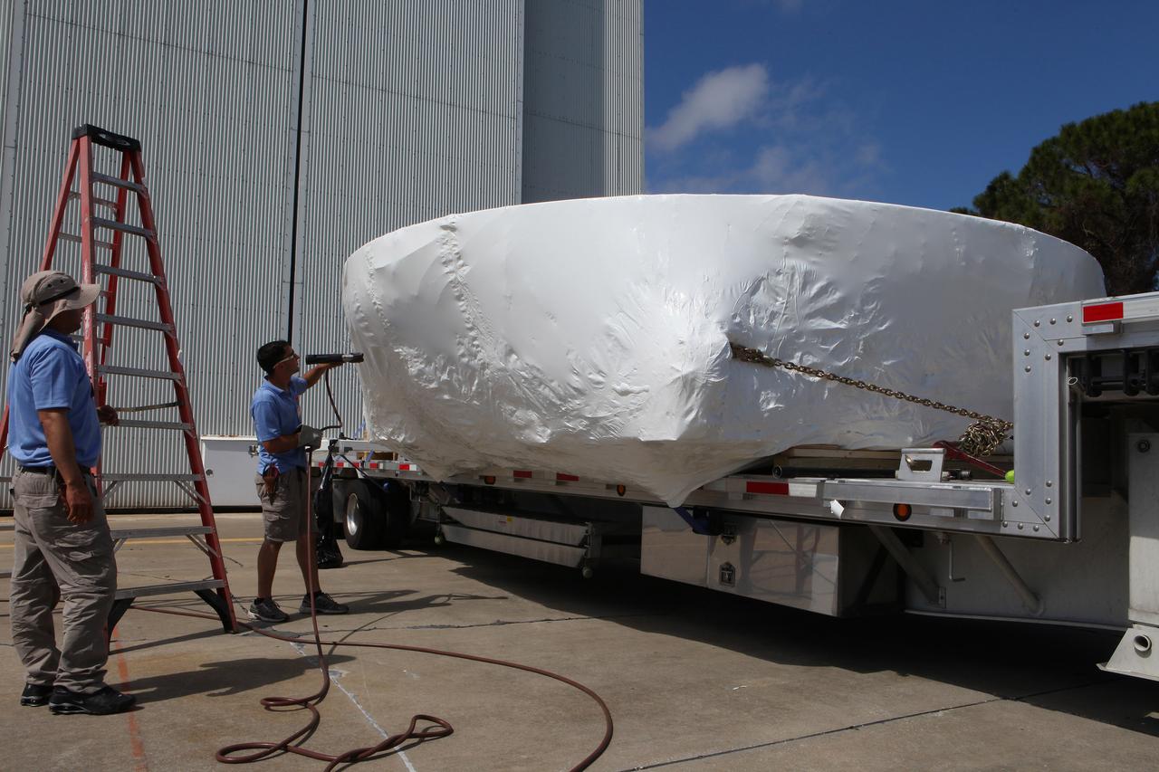
Engineers at Kennedy Space Center prepare the Orion heat shield for transport to Marshall Space Flight Center for testing on March 2, 2015. The heat shield flew on Orion's Exploration Flight Test-1 (EFT-1) in December 2014, protecting the spacecraft from 4000 degree F temperatures during reentry. Part of Batch image transfer from Flickr.
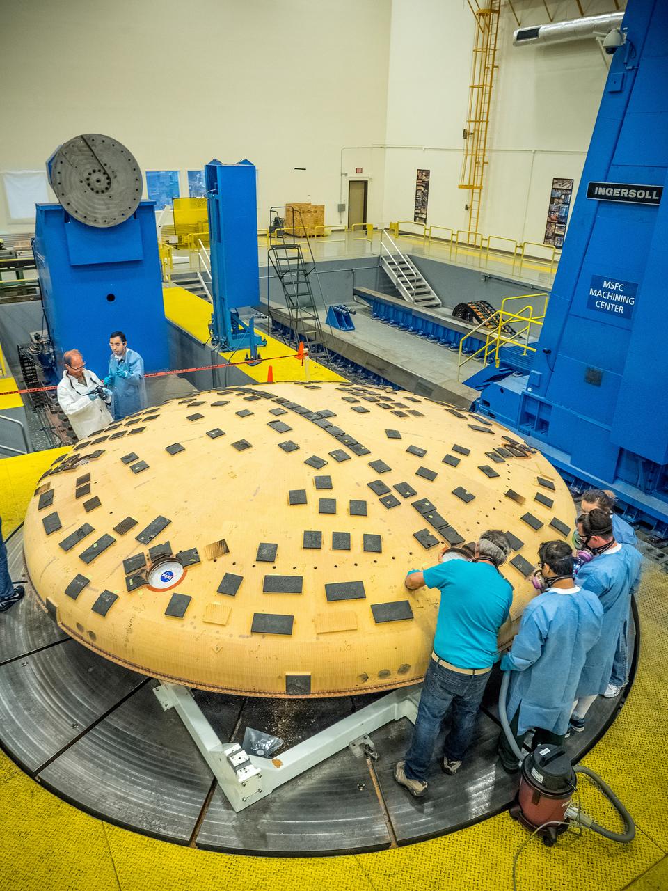
Engineers from NASA's Ames Research Center at Moffett Field, California, and Marshall Space Flight Center in Huntsville, Alabama, remove samples on May 4, 2015, from Orion's heat shield which flew on Exploration Flight Test-1 (EFT-1) in 2014. The heat shield protected the spacecraft from temperatures reaching 4000 degrees F. Part of Batch image transfer from Flickr.
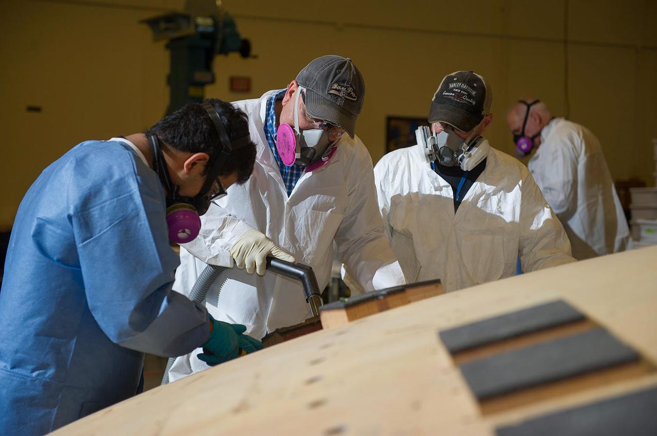
Engineers from NASA's Ames Research Center at Moffett Field, California, and Marshall Space Flight Center in Huntsville, Alabama, remove samples on May 4, 2015, from Orion's heat shield which flew on Exploration Flight Test-1 (EFT-1) in 2014. The heat shield protected the spacecraft from temperatures reaching 4000 degrees F. Part of Batch image transfer from Flickr.
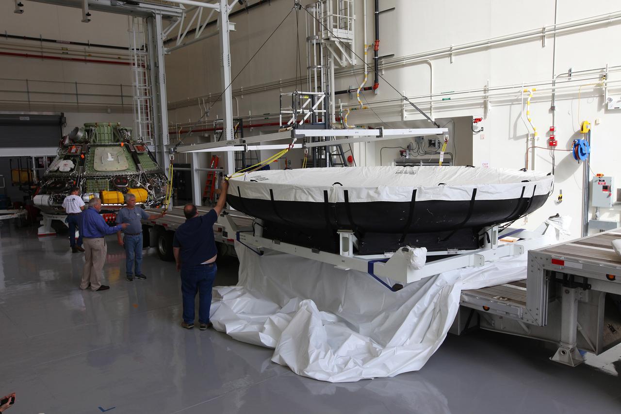
Engineers at Kennedy Space Center prepare the Orion heat shield for transport to Marshall Space Flight Center for testing on March 2, 2015. The heat shield flew on Orion's Exploration Flight Test-1 (EFT-1) in December 2014, protecting the spacecraft from 4000 degree F temperatures during reentry. Part of Batch image transfer from Flickr.
Engineers from NASA's Ames Research Center at Moffett Field, California, and Marshall Space Flight Center in Huntsville, Alabama, remove samples on May 4, 2015, from Orion's heat shield which flew on Exploration Flight Test-1 (EFT-1) in 2014. The heat shield protected the spacecraft from temperatures reaching 4000 degrees F. Part of Batch image transfer from Flickr.
Engineers from NASA's Ames Research Center at Moffett Field, California, and Marshall Space Flight Center in Huntsville, Alabama, remove samples on May 4, 2015, from Orion's heat shield which flew on Exploration Flight Test-1 (EFT-1) in 2014. The heat shield protected the spacecraft from temperatures reaching 4000 degrees F. Part of Batch image transfer from Flickr.
Engineers from NASA's Ames Research Center at Moffett Field, California, and Marshall Space Flight Center in Huntsville, Alabama, remove samples on May 4, 2015, from Orion's heat shield which flew on Exploration Flight Test-1 (EFT-1) in 2014. The heat shield protected the spacecraft from temperatures reaching 4000 degrees F. Part of Batch image transfer from Flickr.
Engineers at Kennedy Space Center prepare the Orion heat shield for transport to Marshall Space Flight Center for testing on March 2, 2015. The heat shield flew on Orion's Exploration Flight Test-1 (EFT-1) in December 2014, protecting the spacecraft from 4000 degree F temperatures during reentry. Part of Batch image transfer from Flickr.
Engineers from NASA's Ames Research Center at Moffett Field, California, and Marshall Space Flight Center in Huntsville, Alabama, remove samples on May 4, 2015, from Orion's heat shield which flew on Exploration Flight Test-1 (EFT-1) in 2014. The heat shield protected the spacecraft from temperatures reaching 4000 degrees F. Part of Batch image transfer from Flickr.
Engineers from NASA's Ames Research Center at Moffett Field, California, and Marshall Space Flight Center in Huntsville, Alabama, remove samples on May 4, 2015, from Orion's heat shield which flew on Exploration Flight Test-1 (EFT-1) in 2014. The heat shield protected the spacecraft from temperatures reaching 4000 degrees F. Part of Batch image transfer from Flickr.
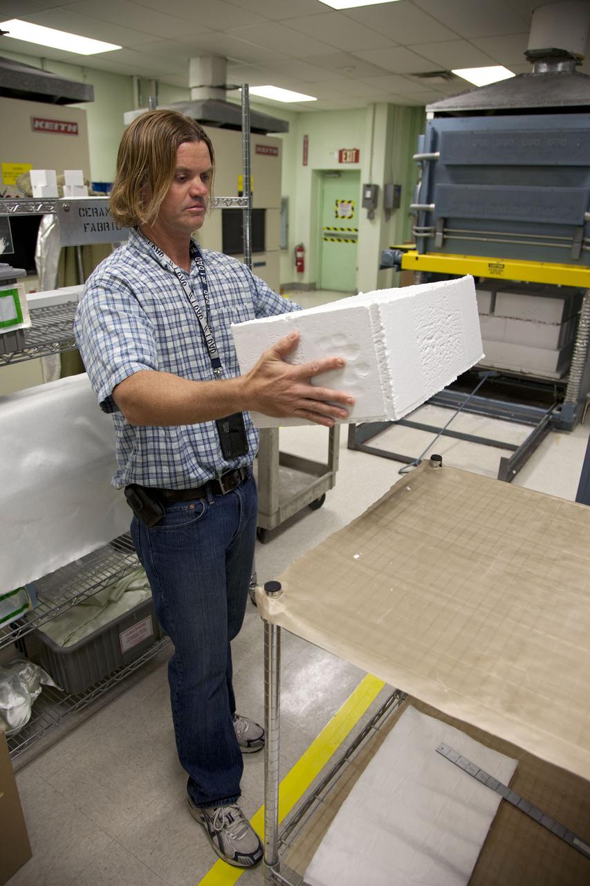
Tim Wright, a United Space Alliance engineering manager at NASA's Kennedy Space Center in Florida, unpacks the heat shield tiles that will be installed to the backshell of the Orion Multi-Purpose Crew Vehicle's Exploration Flight Test EFT-1 capsule. The tiles are being manufactured and inspected in Kennedy's Thermal Protection System Facility. The tiles will be baked at 2,200 degrees F to cure their ceramic coating. EFT-1 will be used during Orion's first test flight in space. For more information, visit www.nasa.gov/orion. Photo credit: Frankie Martin
Engineers at Kennedy Space Center prepare the Orion heat shield for transport to Marshall Space Flight Center for testing on March 2, 2015. The heat shield flew on Orion's Exploration Flight Test-1 (EFT-1) in December 2014, protecting the spacecraft from 4000 degree F temperatures during reentry. Part of Batch image transfer from Flickr.
Engineers at Kennedy Space Center prepare the Orion heat shield for transport to Marshall Space Flight Center for testing on March 2, 2015. The heat shield flew on Orion's Exploration Flight Test-1 (EFT-1) in December 2014, protecting the spacecraft from 4000 degree F temperatures during reentry. Part of Batch image transfer from Flickr.
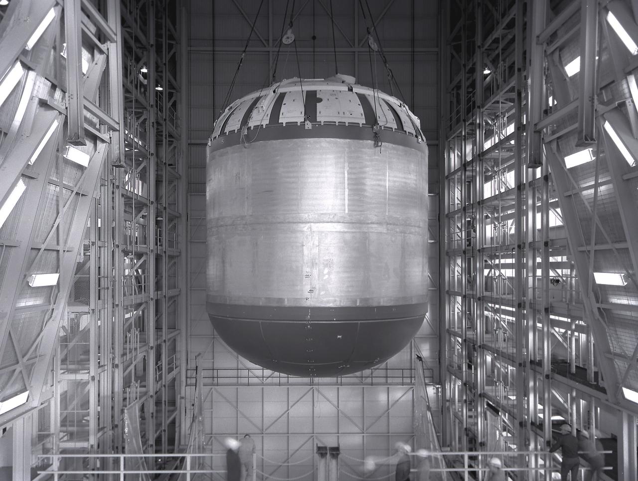
The fuel tank assembly of the Saturn V S-IC (first) stage is readied to be mated to the liquid oxygen tank at the Marshall Space Flight Center. The fuel tank carried kerosene as its fuel. The S-IC stage utilized five F-1 engines that used kerosene and liquid oxygen as propellant. Each engine provided 1,500,000 pounds of thrust. This stage lifted the entire vehicle and Apollo spacecraft from the launch pad.
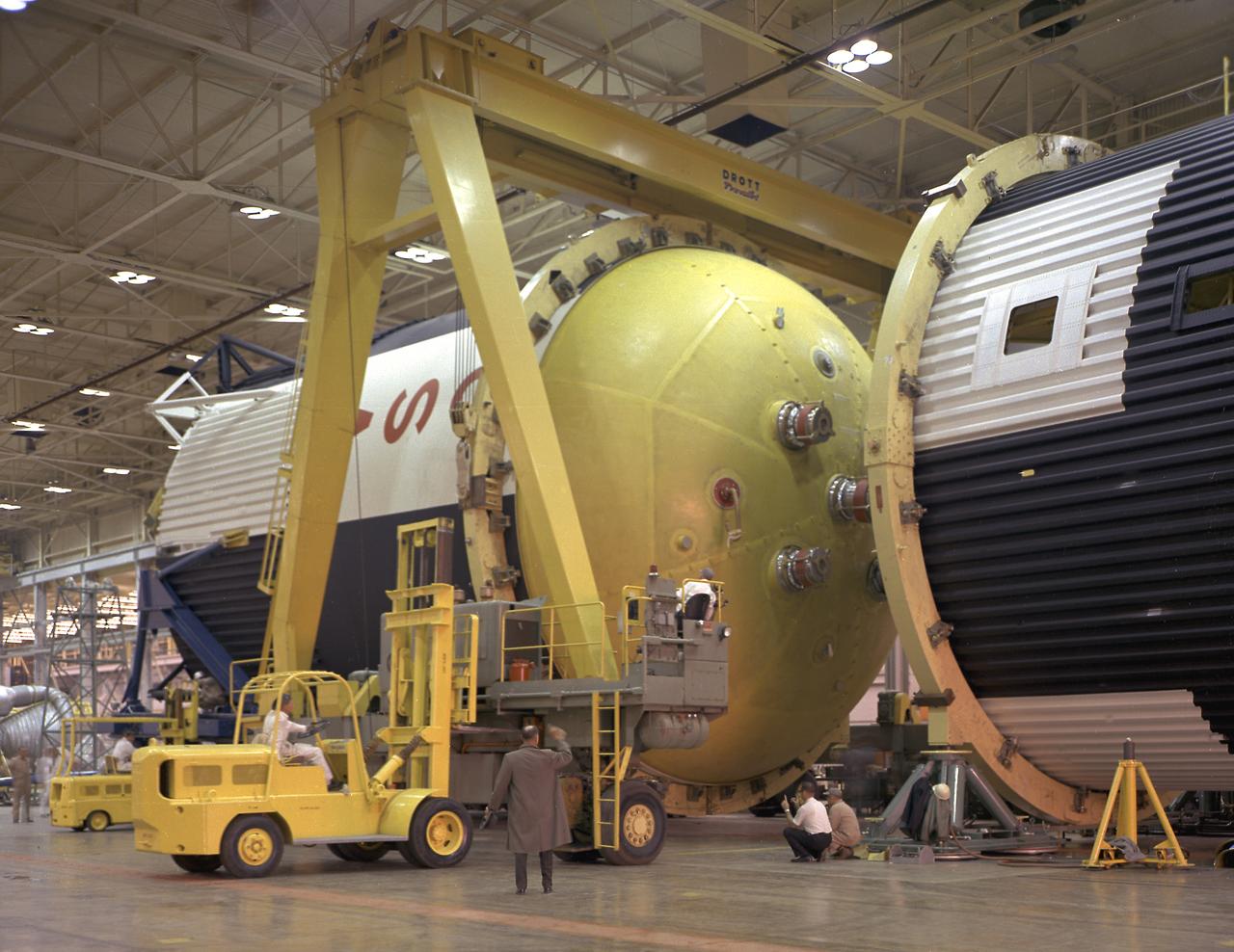
This photograph shows how the fuel tank assembly and the liquid oxygen tank for the Saturn V S-IC (first) stage are placed side by side prior to commencement of the mating of the two stages in the Marshall Space Flight Center, building 4705. The fuel tank carried kerosene as its fuel. The S-IC stage used five F-1 engines, that used kerosene and liquid oxygen as propellant and each engine provided 1,500,000 pounds of thrust. This stage lifted the entire vehicle and Apollo spacecraft from the launch pad.
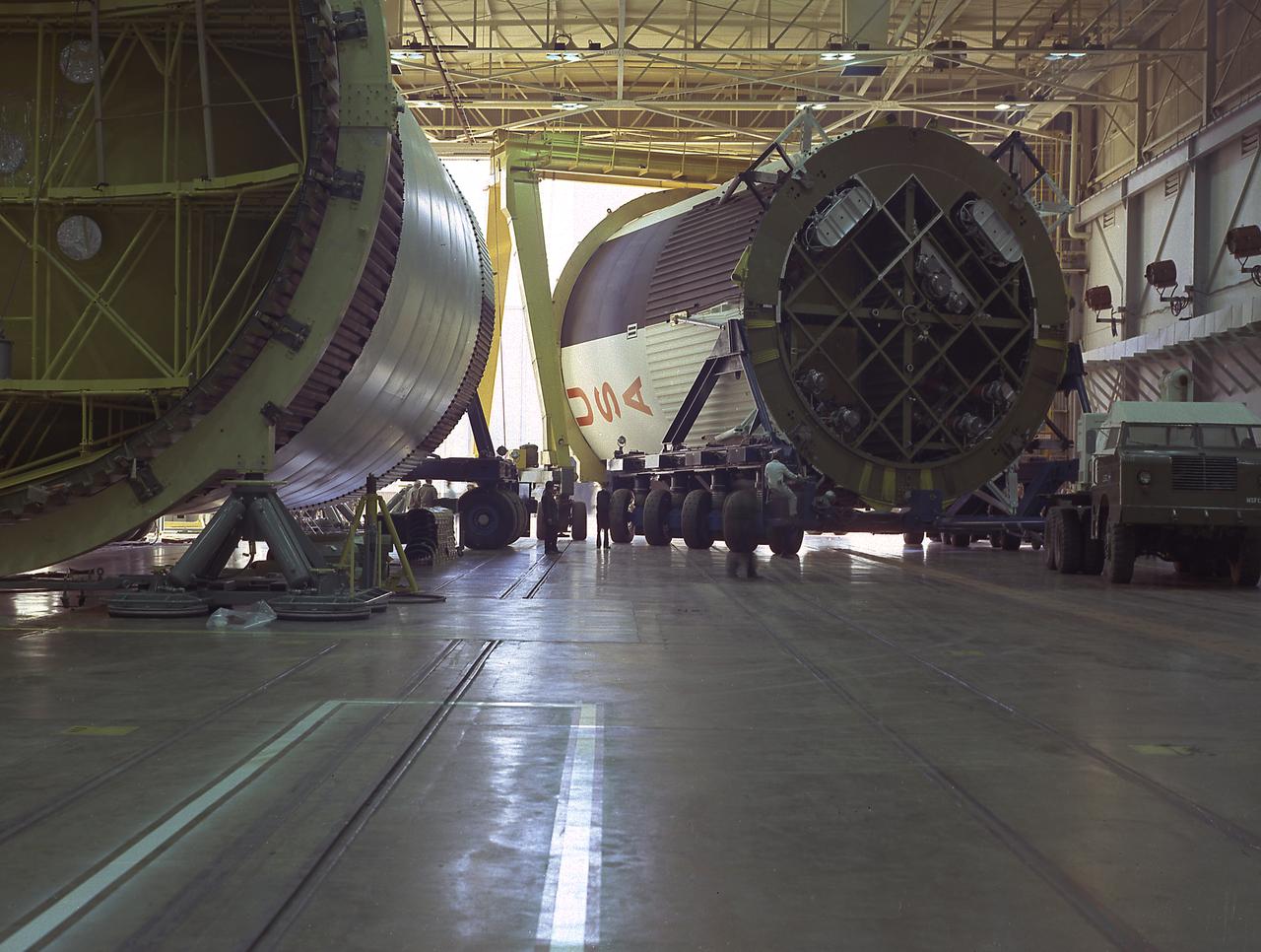
The fuel tank assembly for the Saturn V S-IC (first) stage arrived at the Marshall Space Flight Center, building 4707, for mating to the liquid oxygen tank. The fuel tank carried kerosene as its fuel. The S-IC stage used five F-1 engines, that used kerosene and liquid oxygen as propellant and each engine provided 1,500,000 pounds of thrust. This stage lifted the entire vehicle and Apollo spacecraft from the launch pad.
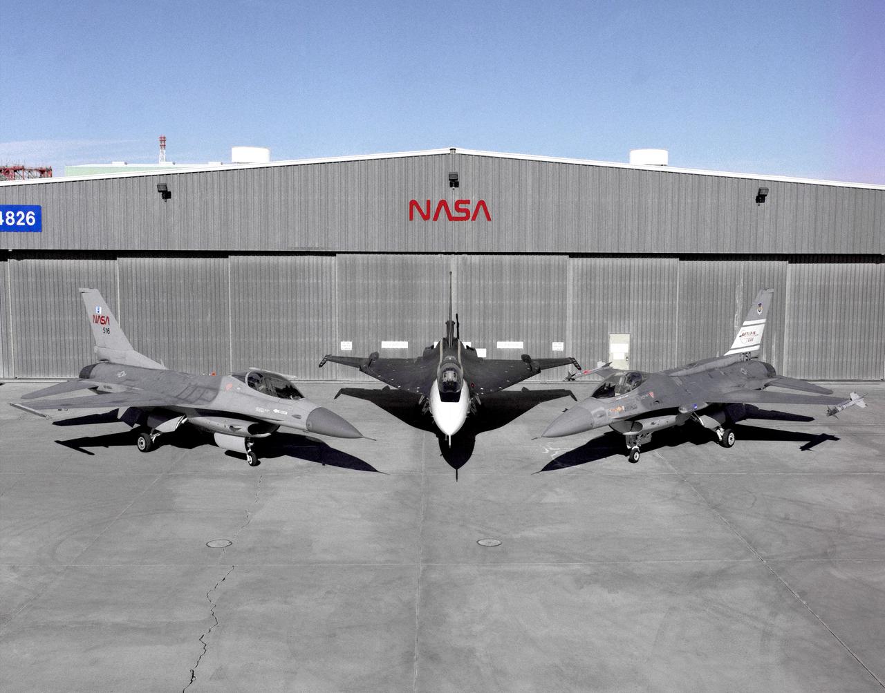
Photographed outside their hangar at the Dryden Flight Research Center, Edwards, California, part of Dryden's F-16 fleet is, left to right; an F-16A, the F-16XL no. 1, and the F-16 AFTI. The F-16A (NASA 516), the only civil registered F-16 in existence, was transferred to Dryden from Langley, and was primarily used in engine tests and for parts. It was subsequently transfered from Dryden. The single-seat F-16XL no. 1 (NASA 849) was most recently used in the Cranked-Arrow Wing Aerodynamics Project (CAWAP) to test boundary layer pressures and distribution. Previously it had been used in a program to investigate the characteristics of sonic booms for NASA's High Speed Research Program. Data from the program will be used in the development of a high speed civilian transport. During the series of sonic boom research flights, the F-16XL was used to probe the shock waves being generated by a NASA SR-71 and record their shape and intensity. The Advanced Fighter Technology Integration (AFTI) F-16 was used to develop and demonstrate technologies to improve navigation and a pilot's ability to find and destroy enemy ground targets day or night, including adverse weather. Earlier research in the joint NASA-Air Force AFTI F-16 program demonstrated voice actuated controls, helmet-mounted sighting and integration of forward-mounted canards with the standard flight control system to achieve uncoupled flight.
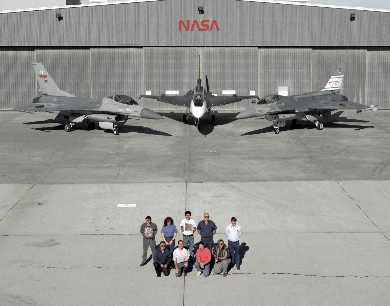
The support crew for the F-16A, the F-16XL no. 1, and the F-16 AFTI are, top row, left to right: Randy Weaver; mechanic, Susan Ligon; mechanic, Bob Garcia; Crew Chief, Rich Kelly; mechanic, Dale Edminister; Avionics Technician. Bottom row, left to right, Art Cope; mechanic, John Huffman; Avionics Technician, Jaime Garcia; Avionics Technician, Don Griffith, Avionics Tech. Co-op student. The F-16A (NASA 516), the only civil registered F-16 in existence, was transferred to Dryden from Langley, and was primarily used in engine tests and for parts. It was subsequently transfered from Dryden. The single-seat F-16XL no. 1 (NASA 849) was most recently used in the Cranked-Arrow Wing Aerodynamics Project (CAWAP) to test boundary layer pressures and distribution. Previously it had been used in a program to investigate the characteristics of sonic booms for NASA's High Speed Research Program. Data from the program will be used in the development of a high speed civilian transport. During the series of sonic boom research flights, the F-16XL was used to probe the shock waves being generated by a NASA SR-71 and record their shape and intensity. The Advanced Fighter Technology Integration (AFTI) F-16 was used to develop and demonstrate technologies to improve navigation and a pilot's ability to find and destroy enemy ground targets day or night, including adverse weather. Earlier research in the joint NASA-Air Force AFTI F-16 program demonstrated voice actuated controls, helmet-mounted sighting and integration of forward-mounted canards with the standard flight control system to achieve uncoupled flight.
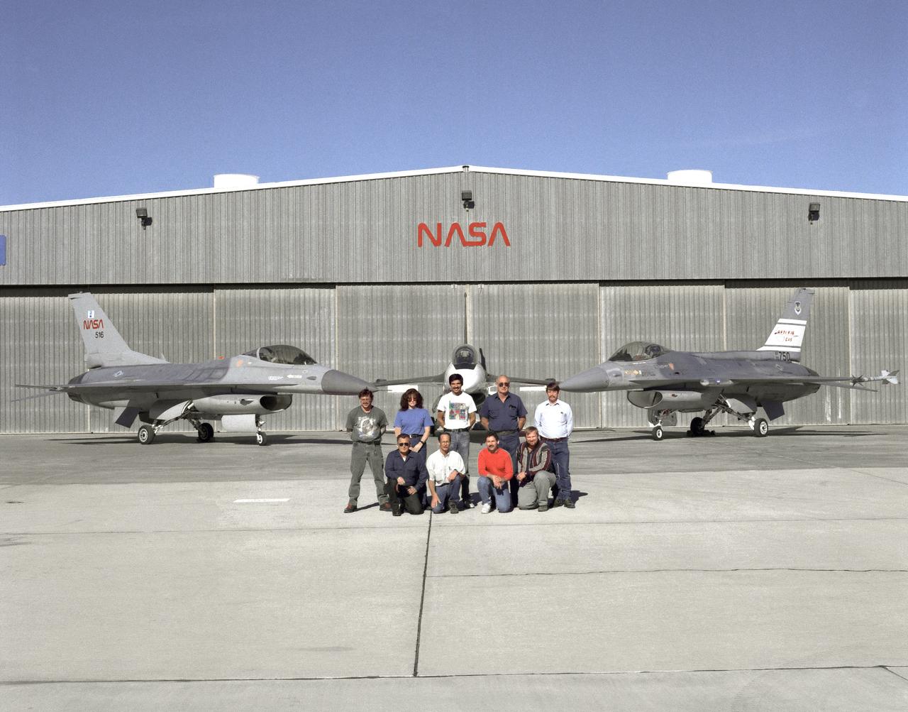
The support crew for the F-16A, the F-16XL no. 1, and the F-16 AFTI are, top row, left to right: Randy Weaver; mechanic, Susan Ligon; mechanic, Bob Garcia; Crew Chief, Rich Kelly; mechanic, Dale Edminister; Avionics Technician. Bottom row, left to right, Art Cope; mechanic, John Huffman; Avionics Technician, Jaime Garcia; Avionics Technician, Don Griffith, Avionics Tech. Co-op student. The F-16A (NASA 516), the only civil registered F-16 in existence, was transferred to Dryden from Langley, and was primarily used in engine tests and for parts. It was subsequently transfered from Dryden. The single-seat F-16XL no. 1 (NASA 849) was most recently used in the Cranked-Arrow Wing Aerodynamics Project (CAWAP) to test boundary layer pressures and distribution. Previously it had been used in a program to investigate the characteristics of sonic booms for NASA's High Speed Research Program. Data from the program will be used in the development of a high speed civilian transport. During the series of sonic boom research flights, the F-16XL was used to probe the shock waves being generated by a NASA SR-71 and record their shape and intensity. The Advanced Fighter Technology Integration (AFTI) F-16 was used to develop and demonstrate technologies to improve navigation and a pilot's ability to find and destroy enemy ground targets day or night, including adverse weather. Earlier research in the joint NASA-Air Force AFTI F-16 program demonstrated voice actuated controls, helmet-mounted sighting and integration of forward-mounted canards with the standard flight control system to achieve uncoupled flight.
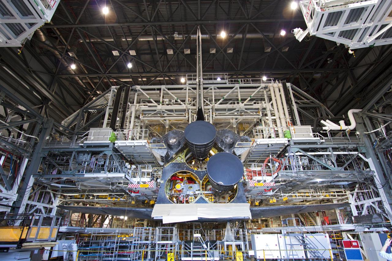
CAPE CANAVERAL, Fla. – Space shuttle Discovery sports two replica shuttle main engines (RSMEs) in Orbiter Processing Facility-1 at NASA’s Kennedy Space Center in Florida. Three RSMEs will be installed on Discovery during Space Shuttle Program transition and retirement activities. The replicas are being built in the Pratt & Whitney Rocketdyne engine shop at Kennedy to replace the shuttle engines which will be placed in storage to support NASA's Space Launch System, under development. Discovery is being prepared for display at the Smithsonian’s National Air and Space Museum Steven F. Udvar-Hazy Center in Chantilly, Va. For more information, visit http://www.nasa.gov/shuttle. Photo credit: NASA/Jim Grossmann
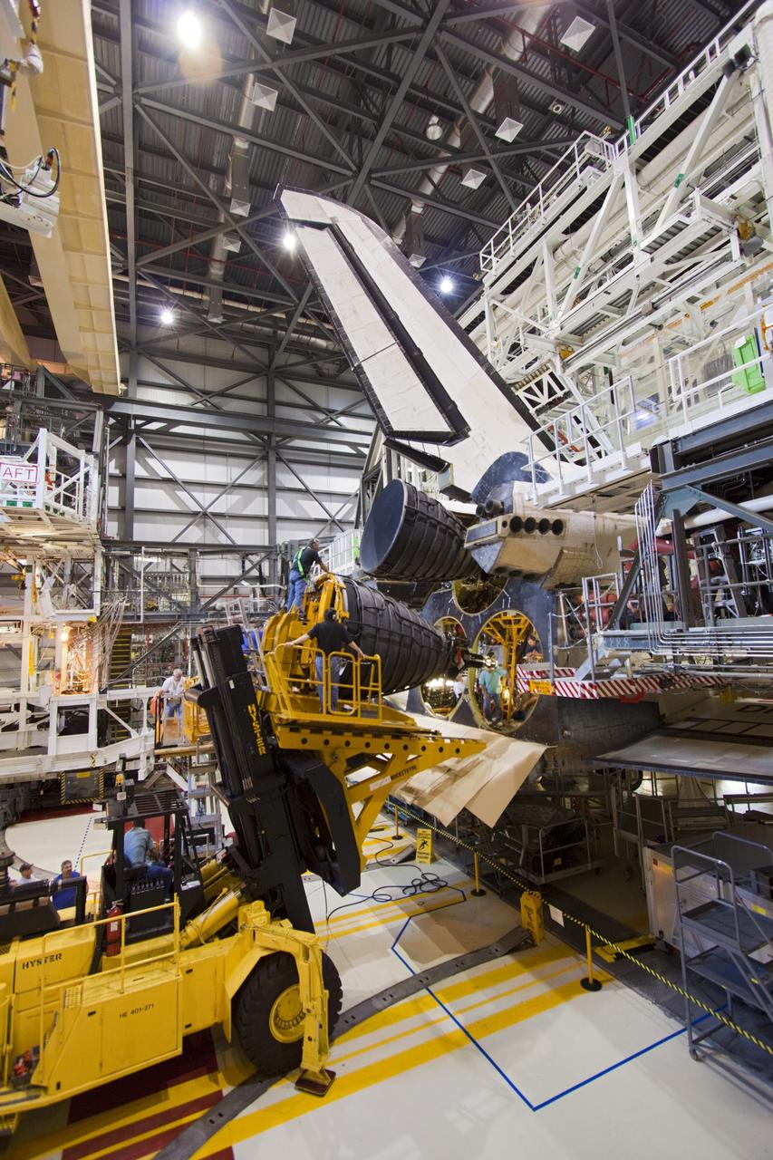
CAPE CANAVERAL, Fla. – A replica shuttle main engine (RSME) is poised for installation on space shuttle Discovery in Orbiter Processing Facility-1 at NASA’s Kennedy Space Center in Florida. The RSME is one of three that will be installed on Discovery during Space Shuttle Program transition and retirement activities. The replicas are being built in the Pratt & Whitney Rocketdyne engine shop at Kennedy to replace the shuttle engines which will be placed in storage to support NASA's Space Launch System, under development. Discovery is being prepared for display at the Smithsonian’s National Air and Space Museum Steven F. Udvar-Hazy Center in Chantilly, Va. For more information, visit http://www.nasa.gov/shuttle. Photo credit: NASA/Jim Grossmann
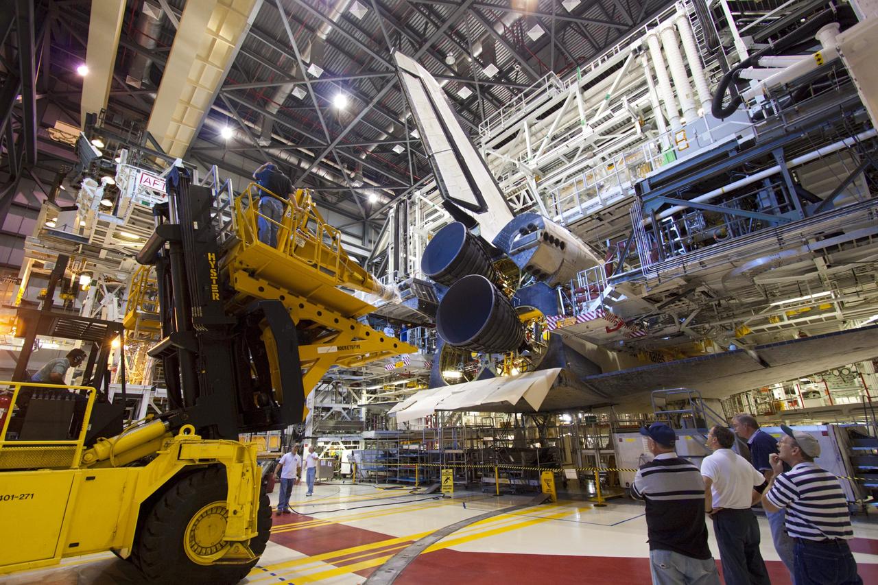
CAPE CANAVERAL, Fla. – Placement of a replica shuttle main engine (RSME) on space shuttle Discovery is complete in Orbiter Processing Facility-1 at NASA’s Kennedy Space Center in Florida. The RSME is one of three that will be installed on Discovery during Space Shuttle Program transition and retirement activities. The replicas are being built in the Pratt & Whitney Rocketdyne engine shop at Kennedy to replace the shuttle engines which will be placed in storage to support NASA's Space Launch System, under development. Discovery is being prepared for display at the Smithsonian’s National Air and Space Museum Steven F. Udvar-Hazy Center in Chantilly, Va. For more information, visit http://www.nasa.gov/shuttle. Photo credit: NASA/Jim Grossmann
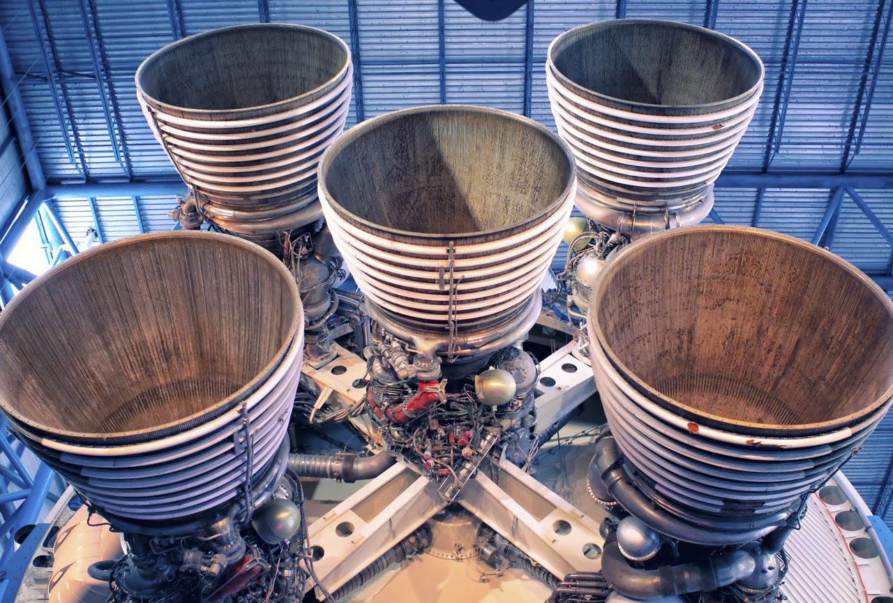
CAPE CANAVERAL, Fla. – As seen on Google Maps, the massive F-1 engines of the Saturn V's first stage on display inside the Apollo/Saturn V Center at the Kennedy Space Center Visitor Complex. Each engine stands 19 feet tall with a diameter of more than 12 feet. The five engines on the first stage produced 7.5 million pounds of thrust at liftoff. The Saturn V was used to launch NASA's Apollo missions to the moon which saw 12 astronauts land and work on the lunar surface. Google precisely mapped Kennedy Space Center and some of its historical facilities for the company's map page. Photo credit: Google/Wendy Wang
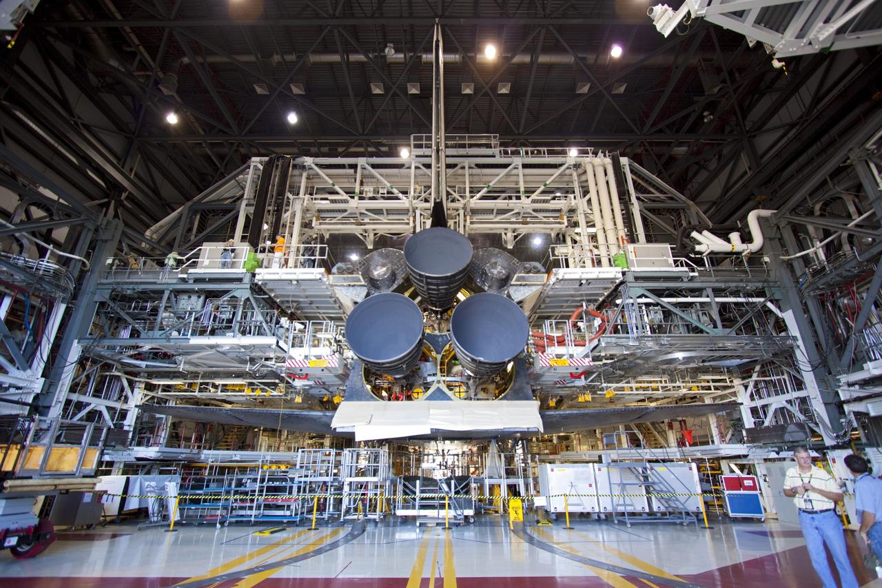
CAPE CANAVERAL, Fla. – Space shuttle Discovery sports three replica shuttle main engines (RSMEs) in Orbiter Processing Facility-1 at NASA’s Kennedy Space Center in Florida. The RSMEs were installed on Discovery during Space Shuttle Program transition and retirement activities. The replicas are built in the Pratt & Whitney Rocketdyne engine shop at Kennedy to replace the shuttle engines which will be placed in storage to support NASA's Space Launch System, under development. Discovery is being prepared for display at the Smithsonian’s National Air and Space Museum Steven F. Udvar-Hazy Center in Chantilly, Va. For more information, visit http://www.nasa.gov/shuttle. Photo credit: NASA/Jim Grossmann
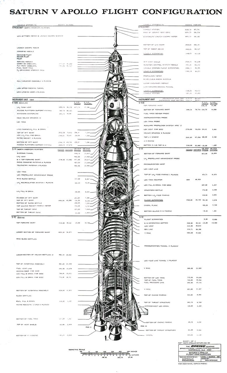
The Saturn V configuration is shown in inches and meters as illustrated by the Boeing Company. The Saturn V vehicle consisted of three stages: the S-IC (first) stage powered by five F-1 engines, the S-II (second) stage powered by five J-2 engines, the S-IVB (third) stage powered by one J-2 engine. A top for the first three stages was designed to contain the instrument unit, the guidance system, the Apollo spacecraft, and the escape system. The Apollo spacecraft consisted of the lunar module, the service module, and the command module. The Saturn V was designed perform lunar and planetary missions and it was capable of placing 280,000 pounds into Earth orbit.
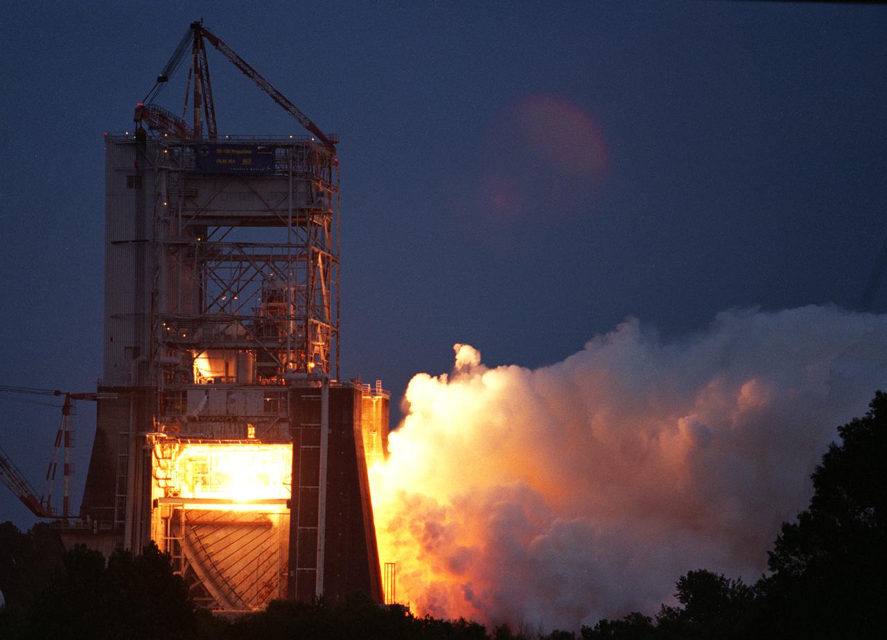
NASA engineers successfully tested a Russian-built rocket engine on November 4, 1998 at the Marshall Space Flight Center (MSFC) Advanced Engine Test Facility, which had been used for testing the Saturn V F-1 engines and Space Shuttle Main engines. The MSFC was under a Space Act Agreement with Lockheed Martin Astronautics of Denver to provide a series of test firings of the Atlas III propulsion system configured with the Russian-designed RD-180 engine. The tests were designed to measure the performance of the Atlas III propulsion system, which included avionics and propellant tanks and lines, and how these components interacted with the RD-180 engine. The RD-180 is powered by kerosene and liquid oxygen, the same fuel mix used in Saturn rockets. The RD-180, the most powerful rocket engine tested at the MSFC since Saturn rocket tests in the 1960s, generated 860,000 pounds of thrust.
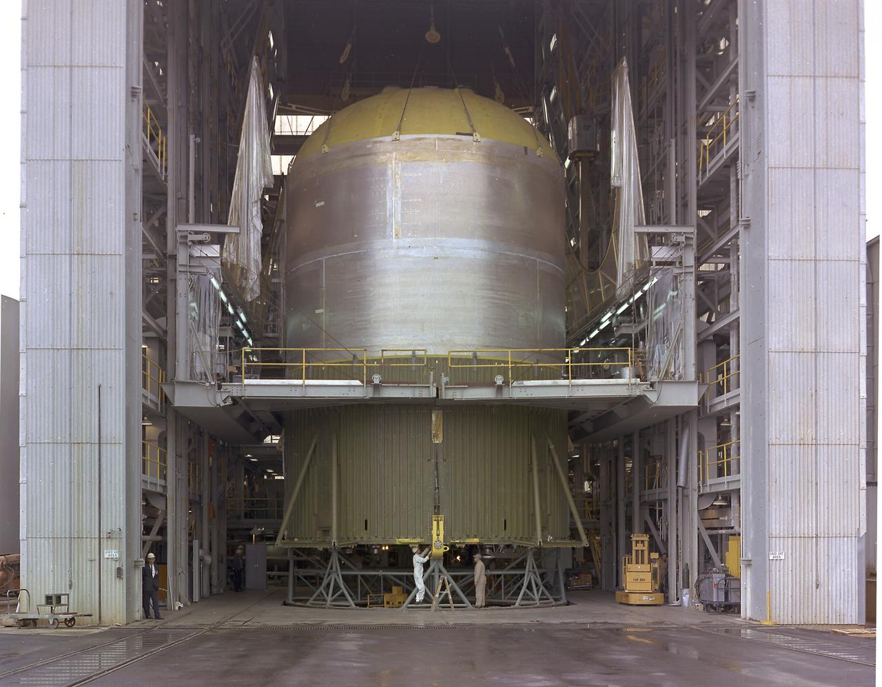
This image shows the Saturn V S-IC-T stage (S-IC static test article) fuel tank being attached to the thrust structure in the vehicle assembly building at the Marshall Space Flight Center (MSFC). The S-IC stage utilized five F-1 engines that used liquid oxygen and kerosene as propellant and provided a combined thrust of 7,500,000 pounds.
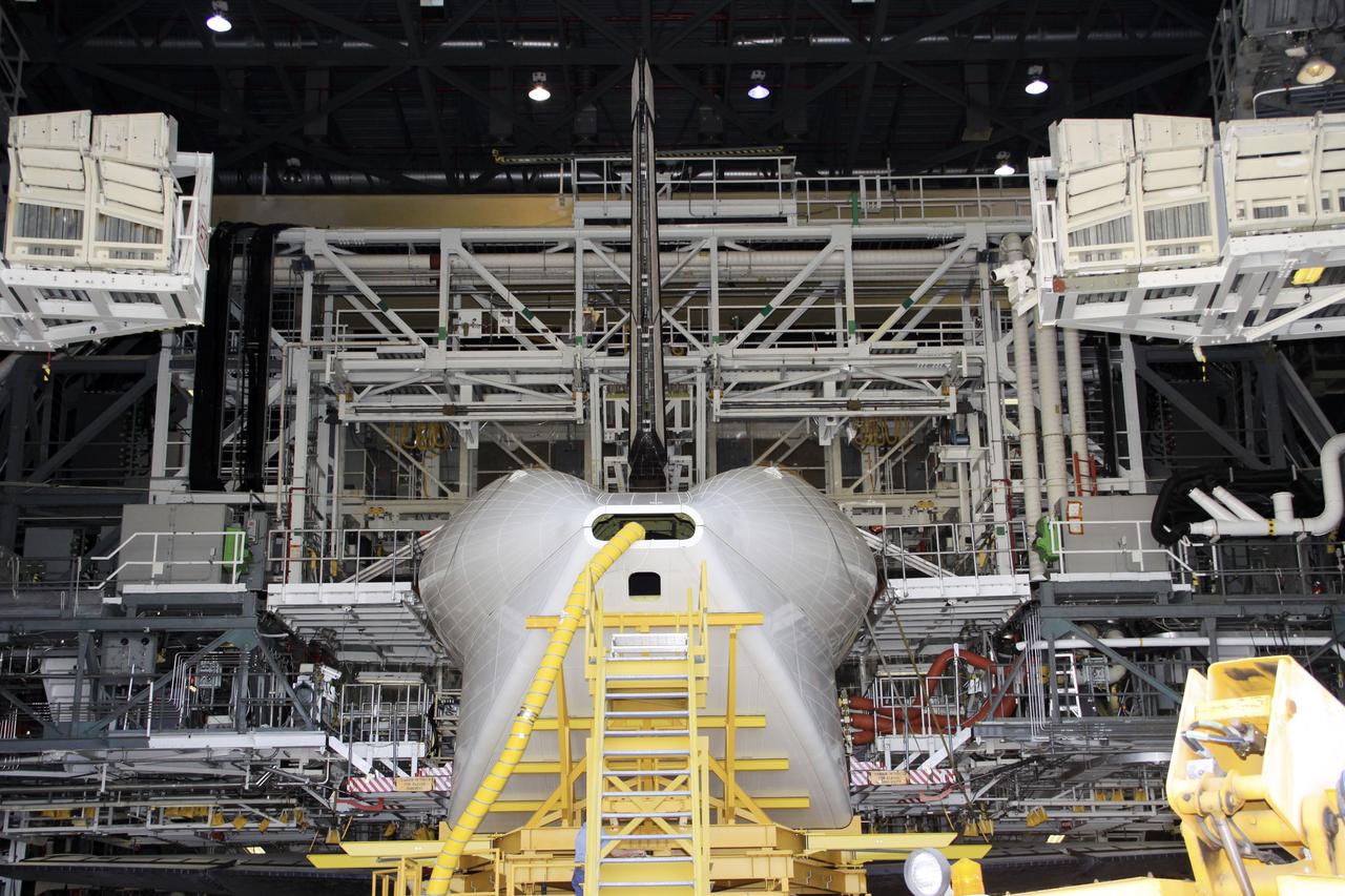
CAPE CANAVERAL, Fla. -- Inside Orbiter Processing Facility-1 at NASA’s Kennedy Space Center in Florida, the tail cone is installed around space shuttle Discovery’s three replica shuttle main engines for protection. The work is part of the Space Shuttle Program’s transition and retirement processing of shuttle Discovery. Discovery is being prepared for display at the Smithsonian’s National Air and Space Museum, Steven F. Udvar-Hazy Center in Chantilly, Va. For more information, visit http://www.nasa.gov/shuttle. Photo credit: NASA/Jim Grossmann
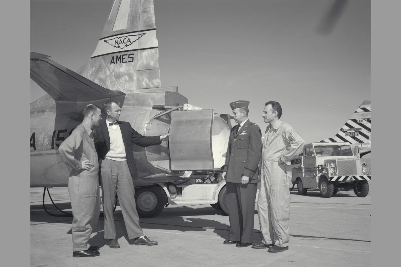
NACA Photographer Thrust reverser on F-94C-1 (AF50-956 NACA 156) Starfire (l to R) Air Force Major E. Sommerich; Ames Engineer Seth Anderson, Lt. Col. Tavasti; and Ames Chief test pilot George Cooper discussing phases of flight evaluation tests. Note: Used in publication in Flight Research at Ames; 57 Years of Development and Validation of Aeronautical Technology NASA SP-1998-3300 fig 91
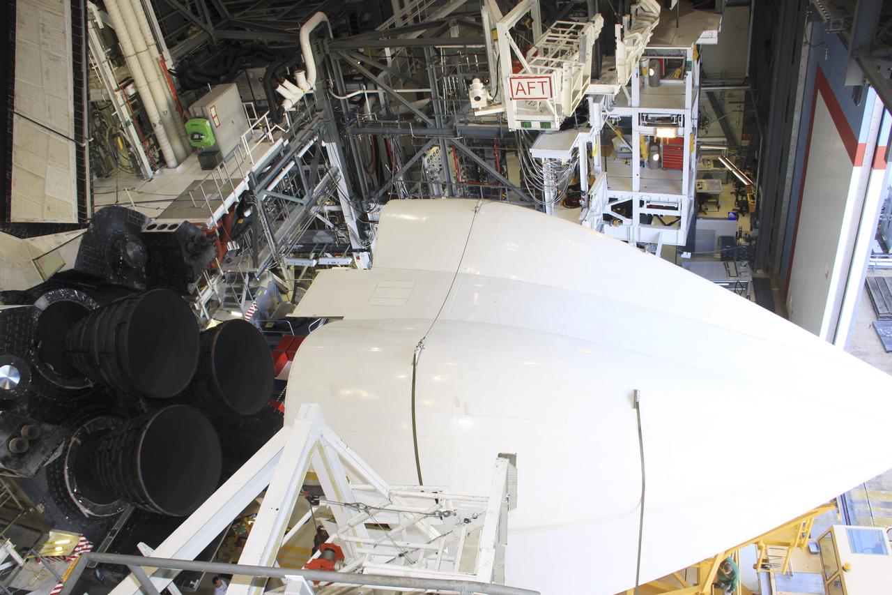
CAPE CANAVERAL, Fla. -- Inside Orbiter Processing Facility-1 at NASA’s Kennedy Space Center in Florida, the tail cone is being installed around Discovery’s three replica shuttle main engines for protection. The work is part of the Space Shuttle Program’s transition and retirement processing of shuttle Discovery. Discovery is being prepared for display at the Smithsonian’s National Air and Space Museum, Steven F. Udvar-Hazy Center in Chantilly, Va. For more information, visit http://www.nasa.gov/shuttle. Photo credit: NASA/Jim Grossmann
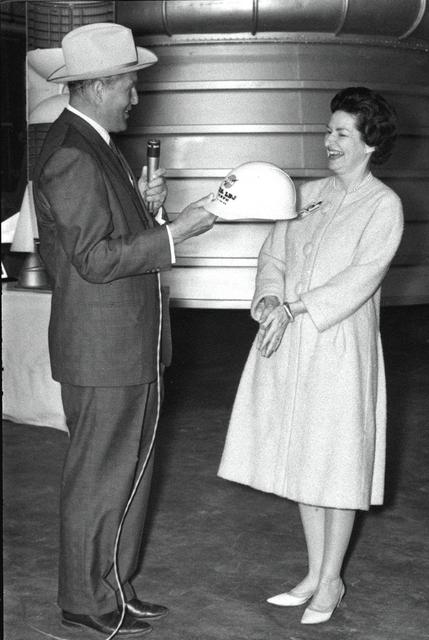
Marshall Space Flight Center Director Dr. Wernher von Braun presents Lady Bird Johnson with an inscribed hard hat during the First Lady's March 24, 1964 visit. While at the Marshall Center, Mrs. Johnson addressed Center employees, toured facilities and witnessed test firings of a Saturn I first stage and an F-1 engine. Dr. von Braun is wearing a Texas hat presented to him months earlier by Lyndon Johnson during a visit to the Johnson ranch in Texas.
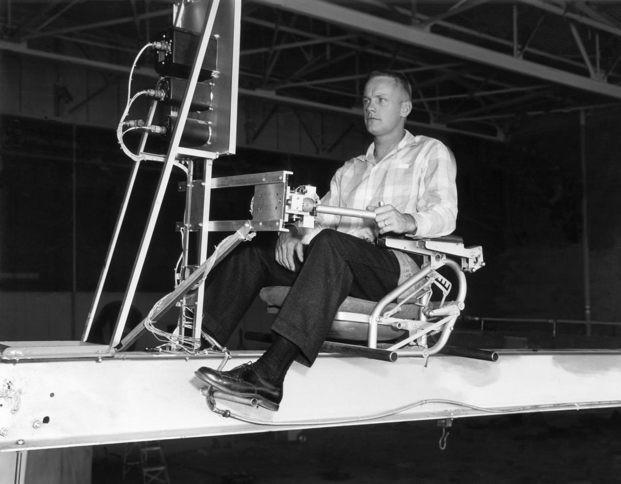
Famed astronaut Neil A. Armstrong, the first man to set foot on the moon during the historic Apollo 11 space mission in July 1969, served for seven years as a research pilot at the NACA-NASA High-Speed Flight Station, now the Dryden Flight Research Center, at Edwards, California, before he entered the space program. Armstrong joined the National Advisory Committee for Aeronautics (NACA) at the Lewis Flight Propulsion Laboratory (later NASA's Lewis Research Center, Cleveland, Ohio, and today the Glenn Research Center) in 1955. Later that year, he transferred to the High-Speed Flight Station at Edwards as an aeronautical research scientist and then as a pilot, a position he held until becoming an astronaut in 1962. He was one of nine NASA astronauts in the second class to be chosen. As a research pilot Armstrong served as project pilot on the F-100A and F-100C aircraft, F-101, and the F-104A. He also flew the X-1B, X-5, F-105, F-106, B-47, KC-135, and Paresev. He left Dryden with a total of over 2450 flying hours. He was a member of the USAF-NASA Dyna-Soar Pilot Consultant Group before the Dyna-Soar project was cancelled, and studied X-20 Dyna-Soar approaches and abort maneuvers through use of the F-102A and F5D jet aircraft. Armstrong was actively engaged in both piloting and engineering aspects of the X-15 program from its inception. He completed the first flight in the aircraft equipped with a new flow-direction sensor (ball nose) and the initial flight in an X-15 equipped with a self-adaptive flight control system. He worked closely with designers and engineers in development of the adaptive system, and made seven flights in the rocket plane from December 1960 until July 1962. During those fights he reached a peak altitude of 207,500 feet in the X-15-3, and a speed of 3,989 mph (Mach 5.74) in the X-15-1. Armstrong has a total of 8 days and 14 hours in space, including 2 hours and 48 minutes walking on the Moon. In March 1966 he was commander of the Gemini 8 or
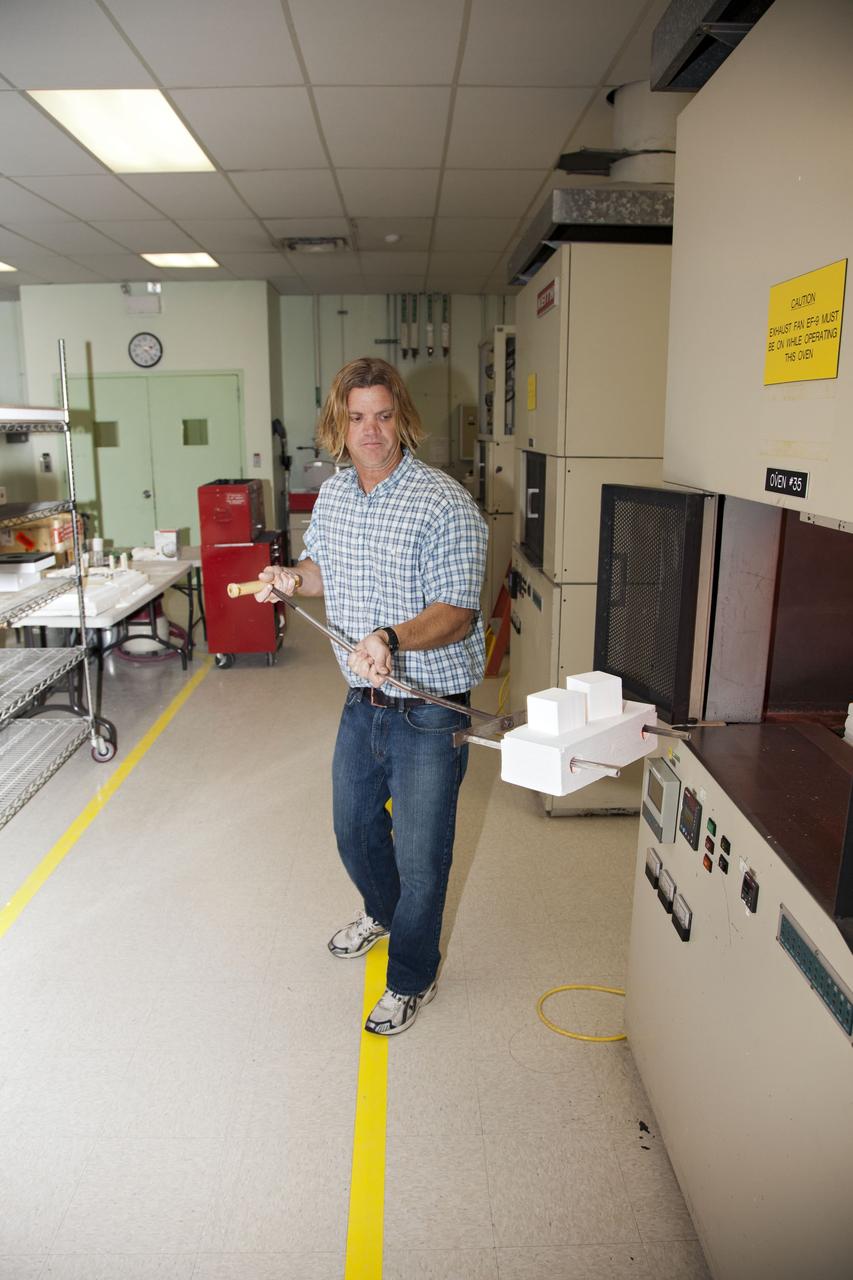
CAPE CANAVERAL, Fla. -- Tim Wright, a United Space Alliance engineering manager at NASA's Kennedy Space Center in Florida, removes the heat shield tiles that will be installed to the backshell of the Orion Multi-Purpose Crew Vehicle's Exploration Flight Test EFT-1 capsule from a Keith thermal automation oven. Inside, the tiles were baked at 2,200 degrees F to cure their ceramic coating. The work to manufacture and inspect the tiles is taking place in Kennedy's Thermal Protection System Facility. EFT-1 will be used during Orion's first test flight in space. For more information, visit www.nasa.gov/orion. Photo credit: Frankie Martin