
NASA Extreme Ultraviolet Imaging Telescope aboard ESA’s SOHO spacecraft took this image of a huge, handle-shaped prominence in 1999. Prominences are huge clouds of relatively cool dense plasma suspended in the Sun hot, thin corona.
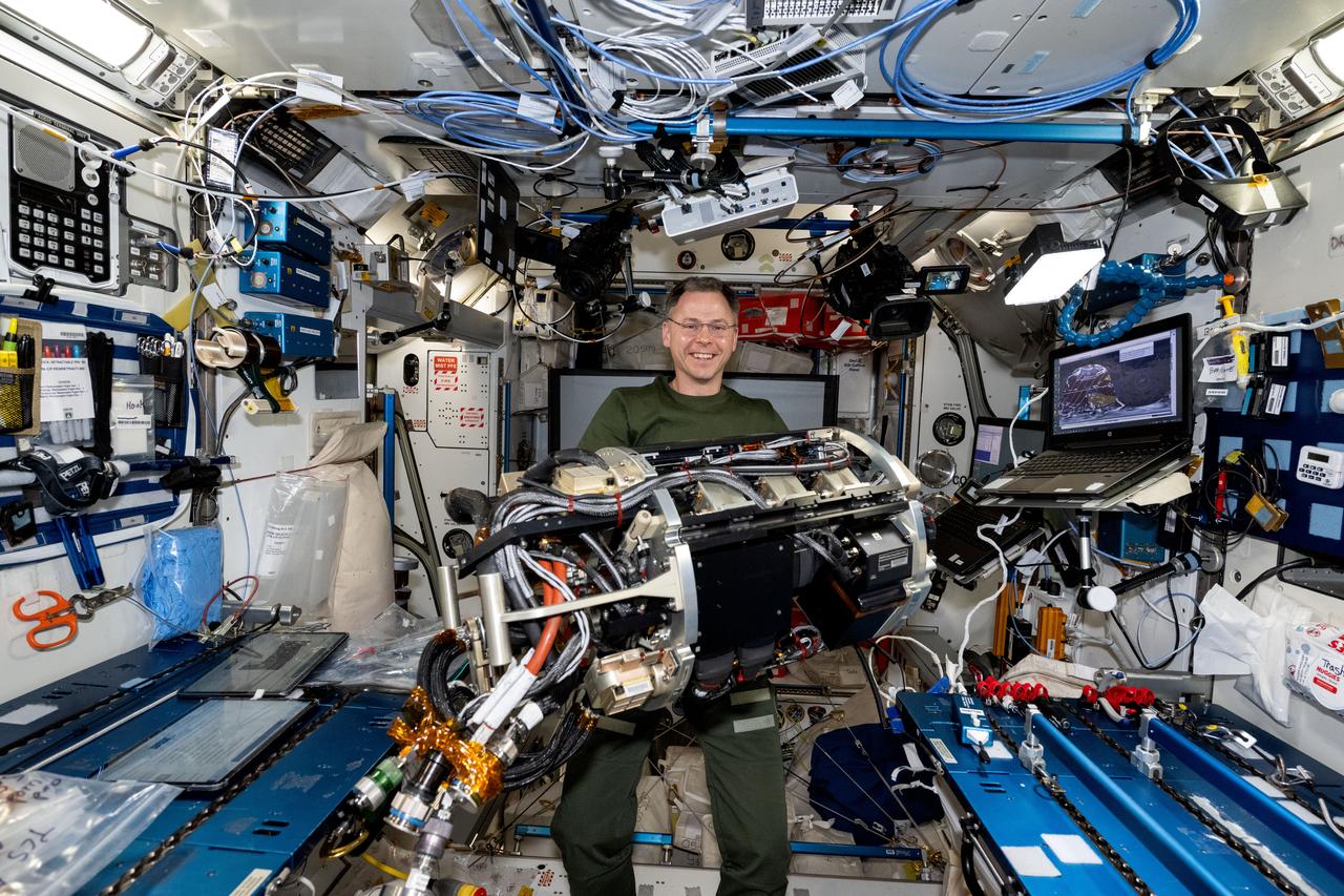
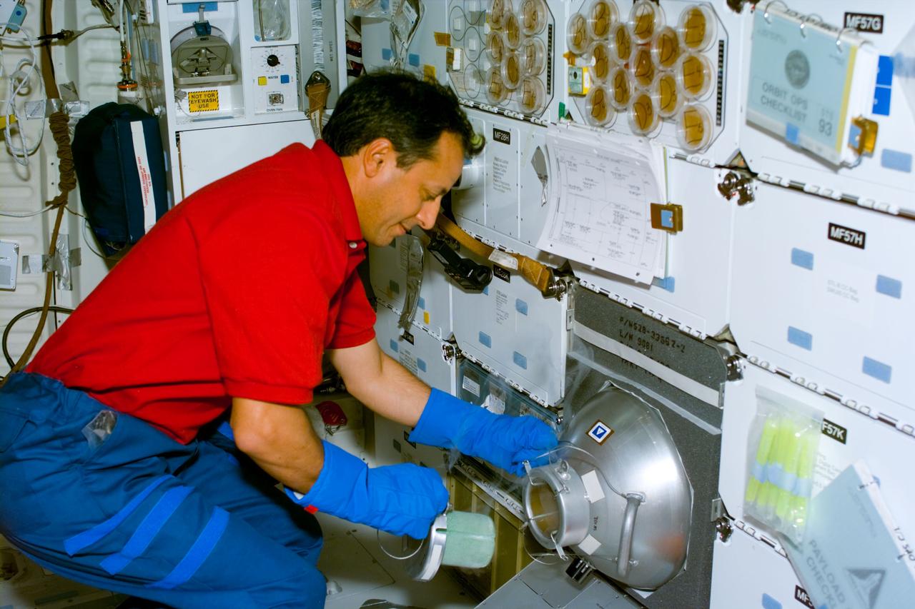
iss072e519705 (Jan. 23, 2025) --- NASA astronaut and Expedition 72 Flight Engineer Nick Hague handles research hardware that is part of the Combustion Integrated Rack that enables safe fuel and flame research aboard the International Space Station.
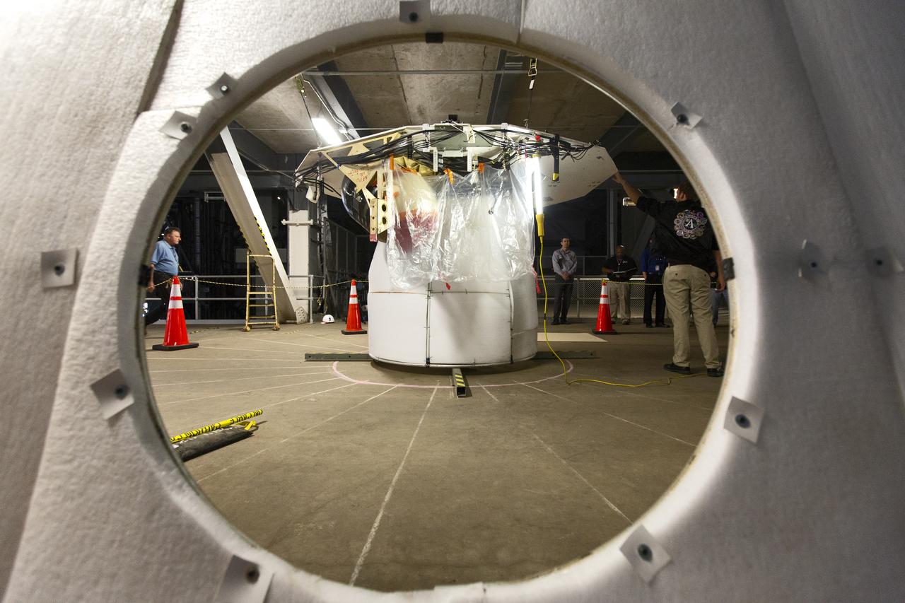
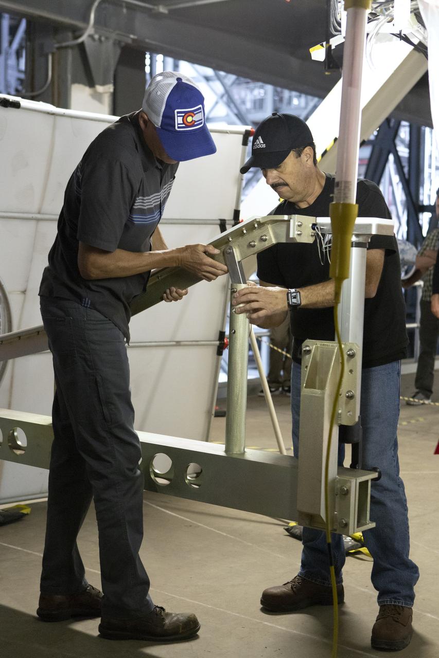
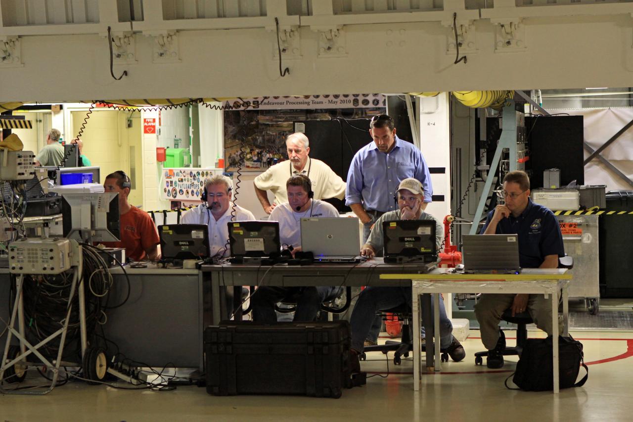
A Space Launch System (SLS) avionics handling tool demonstration takes place inside Kennedy Space Center’s Vehicle Assembly Building on April 4, 2019. The demonstration showed that avionics boxes could be successfully and safely mounted into the SLS rocket’s upper stage — called the Interim Cryogenic Propulsion Stage, or ICPS — with low risk of damaging a closely located hydrazine tank. Avionics boxes include the Inertial Navigation and Control Assembly and flight batteries. The actual installation will take place just weeks before NASA’s SLS rocket and uncrewed Orion spacecraft lift off on Exploration Mission-1 from Launch Pad 39B at Kennedy.
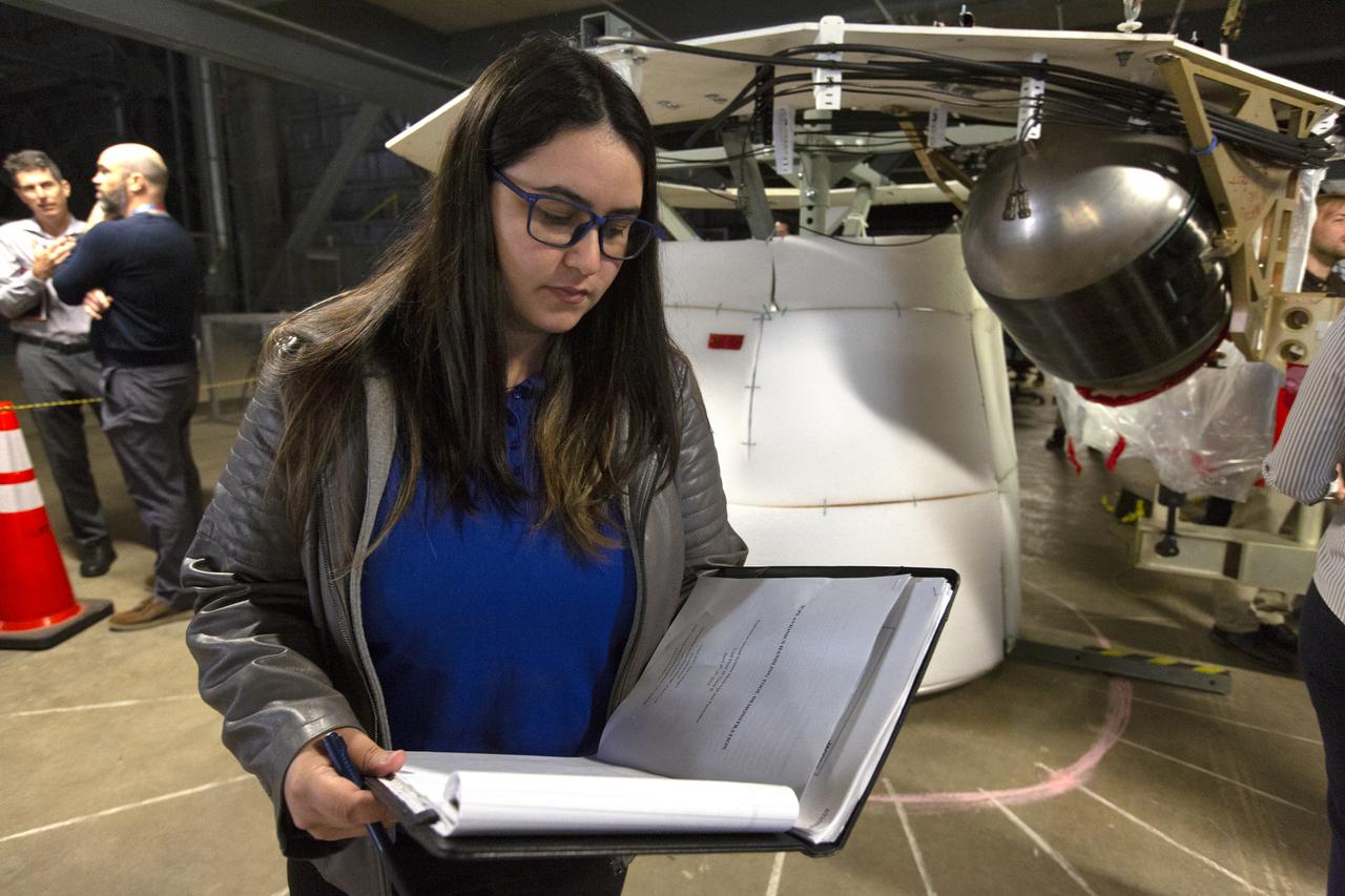
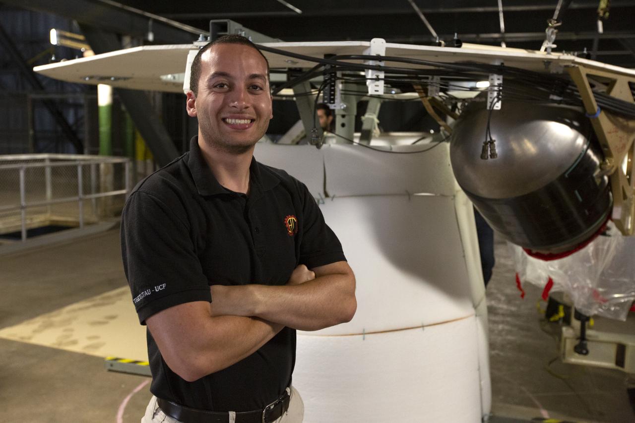
NASA Flight Systems Engineer Sherild Rivera Melendez takes notes during the Space Launch System avionics handling tool demonstration inside Kennedy Space Center’s Vehicle Assembly Building on April 4, 2019. The demonstration showed that avionics boxes could be successfully and safely mounted into the SLS rocket’s upper stage — called the Interim Cryogenic Propulsion Stage, or ICPS — with low risk of damaging a closely located hydrazine tank. Avionics boxes include the Inertial Navigation and Control Assembly and flight batteries. Rivera Melendez coordinated multiple human factors teams, focusing on life cycle reviews and impact risks during installation of the avionics.
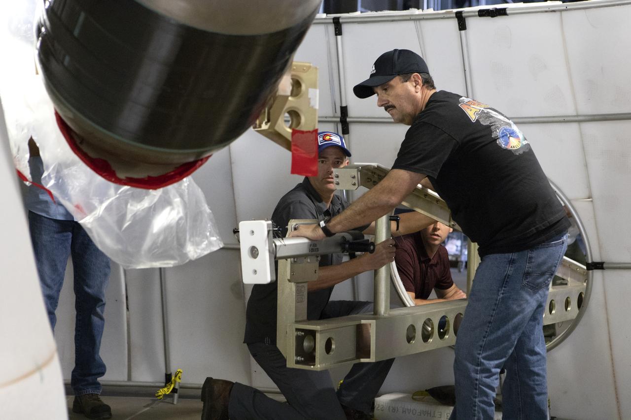
Robert Cook, a launch vehicle engineer with Millennium Engineering and Integration, talks during the Space Launch System (SLS) avionics handling tool demonstration inside Kennedy Space Center’s Vehicle Assembly Building on April 4, 2019. The demonstration showed that avionics boxes could be successfully and safely mounted into the SLS rocket’s upper stage — called the Interim Cryogenic Propulsion Stage, or ICPS — with low risk of damaging a closely located hydrazine tank. Avionics boxes include the Inertial Navigation and Control Assembly and flight batteries. Cook designed the ICPS section mockup used in the exercise.
A Space Launch System (SLS) avionics handling tool demonstration takes place inside Kennedy Space Center’s Vehicle Assembly Building on April 4, 2019. The demonstration showed that avionics boxes could be successfully and safely mounted into the SLS rocket’s upper stage — called the Interim Cryogenic Propulsion Stage, or ICPS — with low risk of damaging a closely located hydrazine tank. Avionics boxes include the Inertial Navigation and Control Assembly and flight batteries. The actual installation will take place just weeks before NASA’s SLS rocket and uncrewed Orion spacecraft lift off on Exploration Mission-1 from Launch Pad 39B at Kennedy.
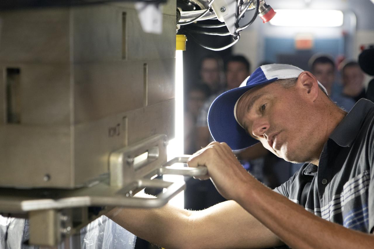
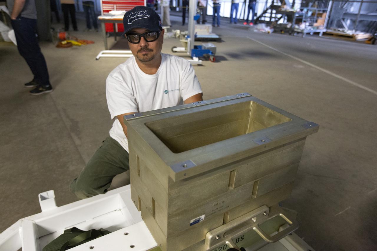
Christopher Di Taranto, a member of the mechanical structures engineering team on the Jacobs Test and Operations Contract, stands in front of an Interim Cryogenic Propulsion Stage (ICPS) mockup during the Space Launch System avionics handling tool demonstration inside Kennedy Space Center’s Vehicle Assembly Building on April 4, 2019. The demonstration showed that avionics boxes could be successfully mounted into the SLS rocket’s upper stage safely, and with low risk of damaging a closely located hydrazine tank. Avionics boxes include the Inertial Navigation and Control Assembly and flight batteries. Di Taranto led a team to quickly resolve a non-conformance issue with the tool.
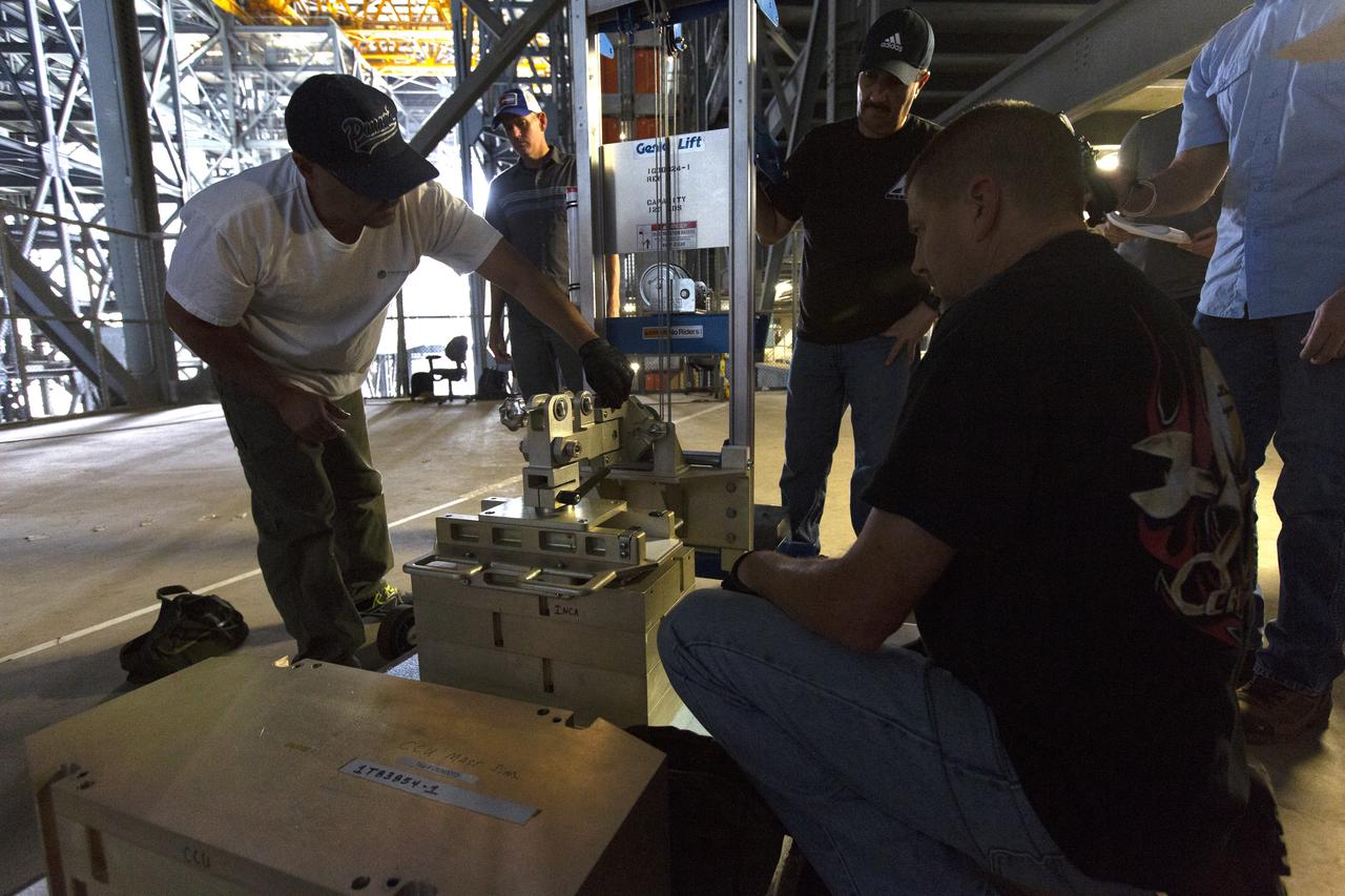
A Space Launch System (SLS) avionics handling tool demonstration takes place inside Kennedy Space Center’s Vehicle Assembly Building on April 4, 2019. The demonstration showed that avionics boxes could be successfully and safely mounted into the SLS rocket’s upper stage — called the Interim Cryogenic Propulsion Stage, or ICPS — with low risk of damaging a closely located hydrazine tank. Avionics boxes include the Inertial Navigation and Control Assembly and flight batteries. The actual installation will take place just weeks before NASA’s SLS rocket and uncrewed Orion spacecraft lift off on Exploration Mission-1 from Launch Pad 39B at Kennedy.
A Space Launch System (SLS) avionics handling tool demonstration takes place inside Kennedy Space Center’s Vehicle Assembly Building on April 4, 2019. The demonstration showed that avionics boxes could be successfully and safely mounted into the SLS rocket’s upper stage — called the Interim Cryogenic Propulsion Stage, or ICPS — with low risk of damaging a closely located hydrazine tank. Avionics boxes include the Inertial Navigation and Control Assembly and flight batteries. The actual installation will take place just weeks before NASA’s SLS rocket and uncrewed Orion spacecraft lift off on Exploration Mission-1 from Launch Pad 39B at Kennedy.
A Space Launch System (SLS) avionics handling tool demonstration takes place inside Kennedy Space Center’s Vehicle Assembly Building on April 4, 2019. The demonstration showed that avionics boxes could be successfully and safely mounted into the SLS rocket’s upper stage — called the Interim Cryogenic Propulsion Stage, or ICPS — with low risk of damaging a closely located hydrazine tank. Avionics boxes include the Inertial Navigation and Control Assembly and flight batteries. The actual installation will take place just weeks before NASA’s SLS rocket and uncrewed Orion spacecraft lift off on Exploration Mission-1 from Launch Pad 39B at Kennedy.
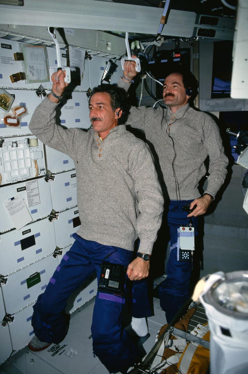
STS035-10-005 (2-10 Dec 1990) --- STS-35 Mission Specialist (MS) Jeffrey A. Hoffman (front) and Pilot Guy S. Gardner, holding Development Test Objective (DTO) 634 trash compactor handles to the ceiling, "commute" to work on the middeck of Columbia, Orbiter Vehicle (OV) 102. Just below Hoffman's right elbow in locker MF43G DTO 634, Trash Compaction and Retention System Demonstration, trash compactor with a geared mechanism that allows manual compaction of wet and dry trash is visible. Also in the view are the stowed treadmill on the middeck floor and the starboard side sleep station.
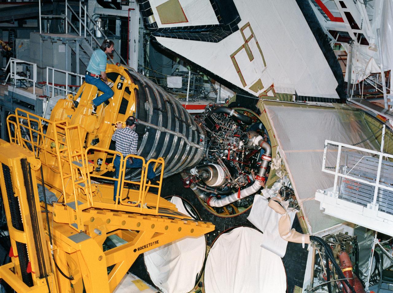
S88-29076 (10 Jan 1988) --- KSC employees work together to carefully guide a 7,000 pound main engine into the number one position in Discovery's aft compartment. Because of the engine's weight and size, special handling equipment is needed to perform the installation. Discovery is currently being prepared for the upcoming STS-26 mission in bay 1 of the Orbiter Processing Facility. This engine, 2019, arrived at KSC on Jan. 6 and was installed Jan. 10. The other two engines are scheduled to be installed later this month. The shuttle's three main liquid fueled engines provide the main propulsion for the orbiter vehicle. The cluster of three engines operate in parallel with the solid rocket boosters during the initial ascent.
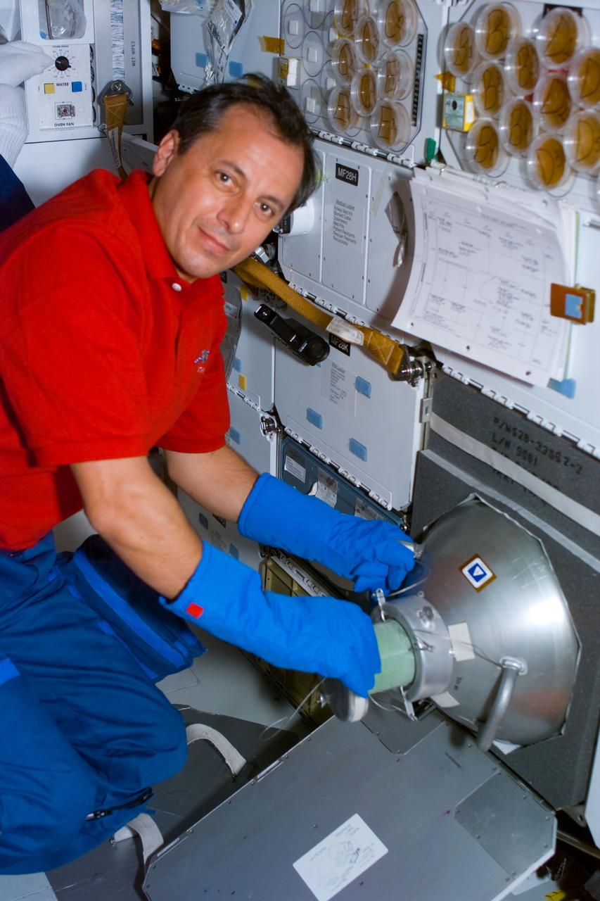
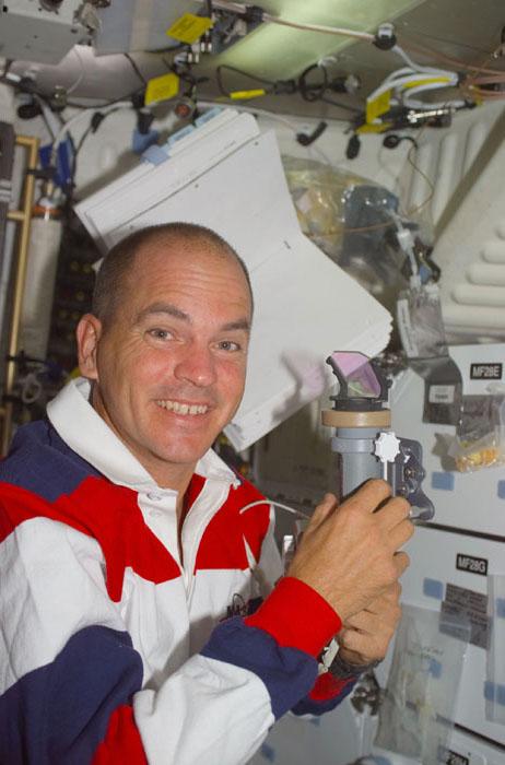
S93-E-5009 (22-27 July 1999) --- Astronaut Michel Tognini, mission specialist, is photographed on the mid deck of the Earth-orbiting Space Shuttle Columbia as he handles the Biological Research in Canisters (BRIC) GN2 freezer. Tognini represents France?s Centre National d?Etudes Spatiales (CNES). The photo was recorded with an electronic still camera (ESC).
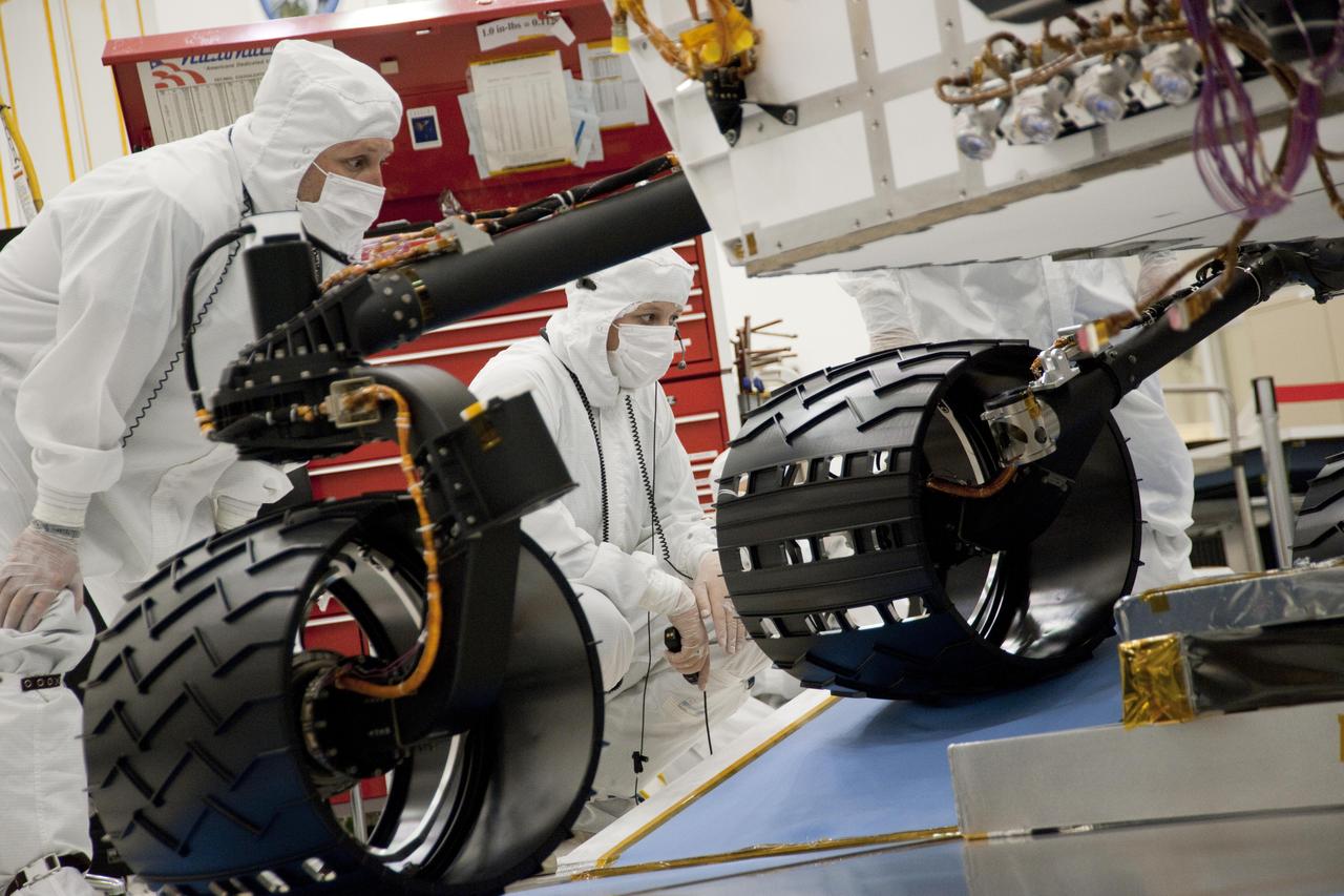
Test operators monitor how NASA Mars rover Curiosity handles driving over a ramp during a test on Sept. 10, 2010, inside the Spacecraft Assembly Facility at NASA Jet Propulsion Laboratory, Pasadena, Calif.
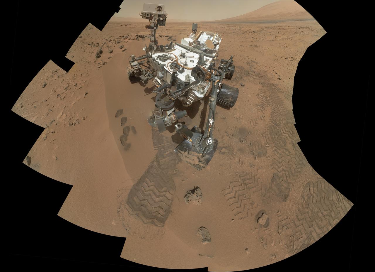
This mosaic from NASA Mars rover, Curiosity, shows the first four of five places from which the rover scoop obtained sand to clean the sample handling and processing system.
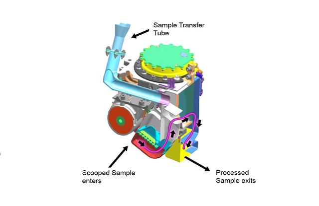
This cutaway view shows the internal chambers of the Collection and Handling for In-Situ Martian Rock Analysis CHIMRA device, attached to the turret at the end of the robotic arm on NASA Curiosity Mars rover.
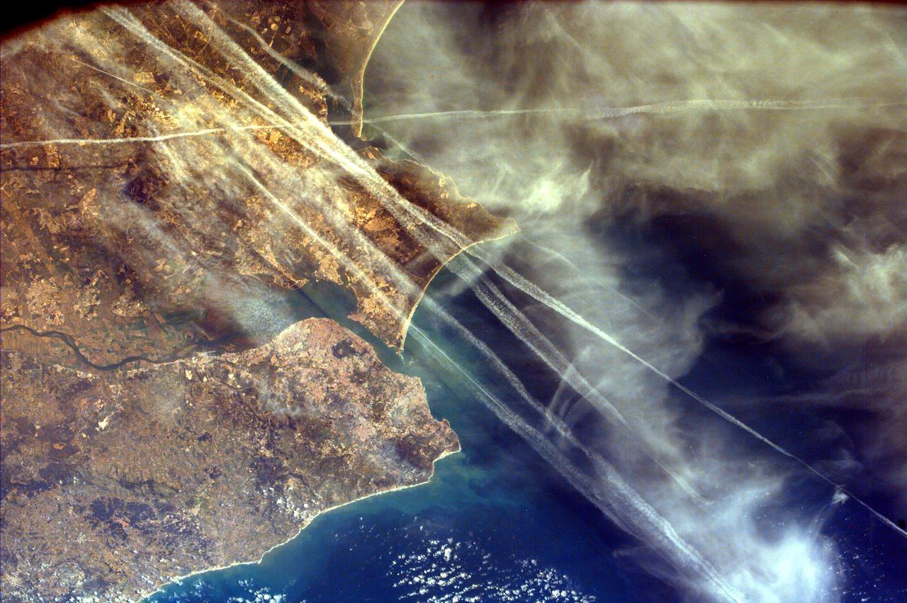
This image from NASA EarthKAM shows Lisbon, the capital of Portugal. The superb natural harbor at Lisbon is a commercially important European port handling much of the import-export traffic for Portugal and Spain.
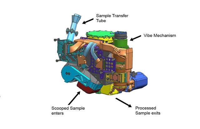
This false-color engineering drawing shows the Collection and Handling for In-Situ Martian Rock Analysis CHIMRA device, attached to the turret at the end of the robotic arm on NASA Curiosity Mars rover.
A crew member handles liquid nitrogen servicing for NASA’s Armstrong Flight Research Center’s ER-2 aircraft at Edwards, California, on Thursday, Aug. 21, 2025. Liquid nitrogen is used to support key science instruments for extended flight durations in critical research missions, such as the Geological Earth Mapping Experiment (GEMx), which requires flights of up to eight hours at approximately 65,000 feet altitude.
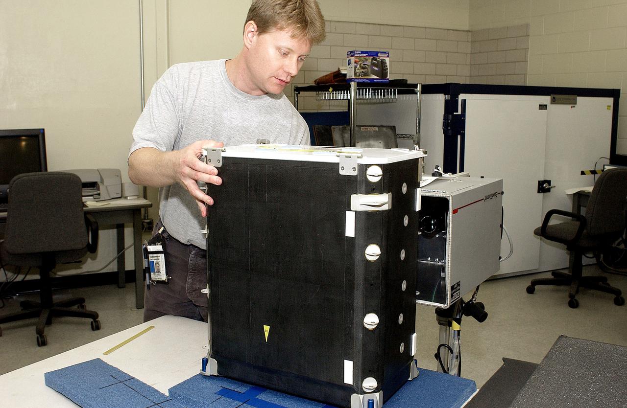
KENNEDY SPACE CENTER, FLA. - In the Vehicle Assembly Building, Jim Landy, NDE specialist, sets up a flight crew lockers for flash thermography. He is screening the lockers for hidden damage underneath dings and dents that might occur during handling.
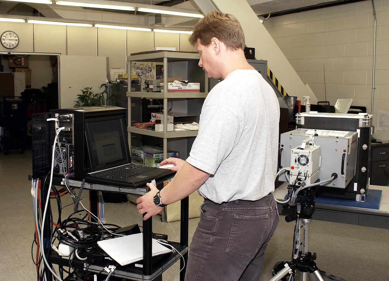
KENNEDY SPACE CENTER, FLA. - In the Vehicle Assembly Building, Jim Landy, NDE specialist, performs flash thermography on flight crew lockers. He is screening the lockers for hidden damage underneath dings and dents that might occur during handling.
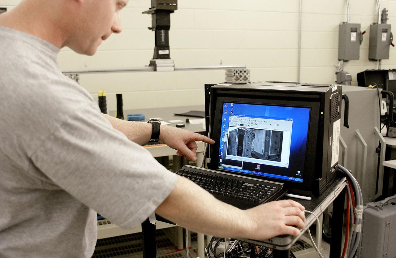
KENNEDY SPACE CENTER, FLA. - In the Vehicle Assembly Building, Jim Landy, NDE specialist, examines flight crew lockers using flash thermography. He is screening the lockers for hidden damage underneath dings and dents that might occur during handling.
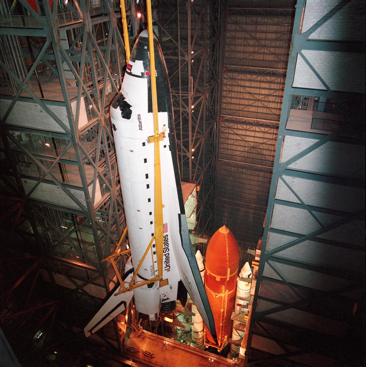
STS-27 Atlantis, Orbiter Vehicle (OV) 104, is suspended via overhead crane, attached at four points, in the Kennedy Space Center (KSC) Vehicle Assembly Building (VAB). Below OV-104 on the mobile launcher platform are the external tank (ET) and solid rocket boosters (SRBs). During ET/SRB mating operations, OV-104 will be mounted atop the ET.
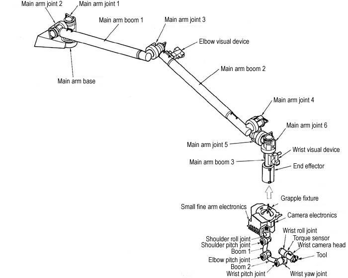
JSC2003-E-42547 (For Release: 18 June 2003) --- This graphic shows the Kibo Japanese Experiment Module (JEM) Remote Manipulator System (RMS). The RMS is used to exchange experiment payloads or hardware located on the JEM Exposed Facility and Experiment Logistics Module - Exposed Section and from inside the Pressurized Module through a scientific airlock, support maintenance tasks of Kibo and handle orbital replacement units (ORUs). The Main Arm can handle up to seven tons (14,000 pounds) of hardware and the Small Fine Arm, when attached to the Main Arm, handles more delicate operations. Photo Credit: NASDA
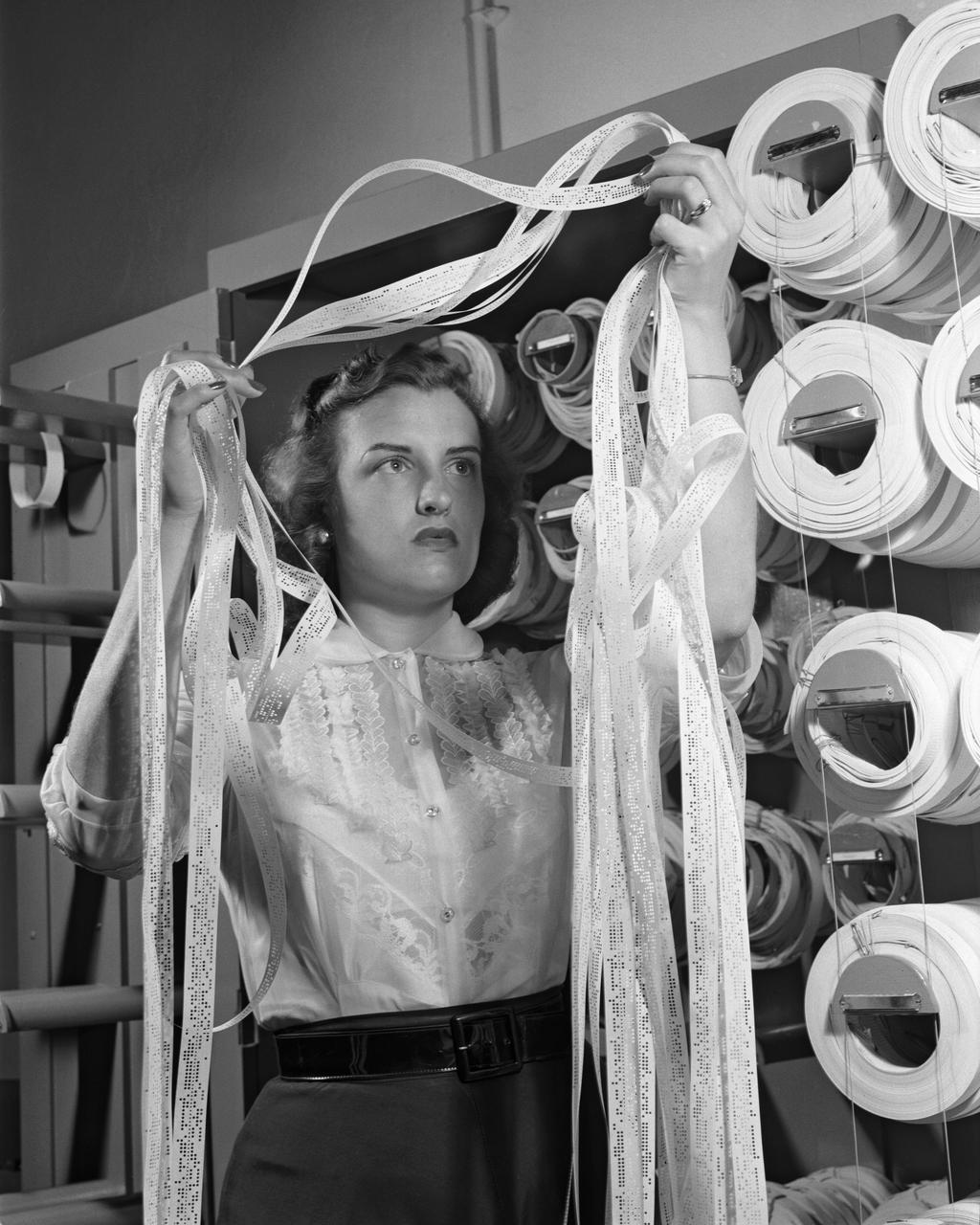
Women Adequately Filling Posts In NACA Laboratory: Mrs. Doris Rudd Porter Baron handling Manometertape, Bell computer.
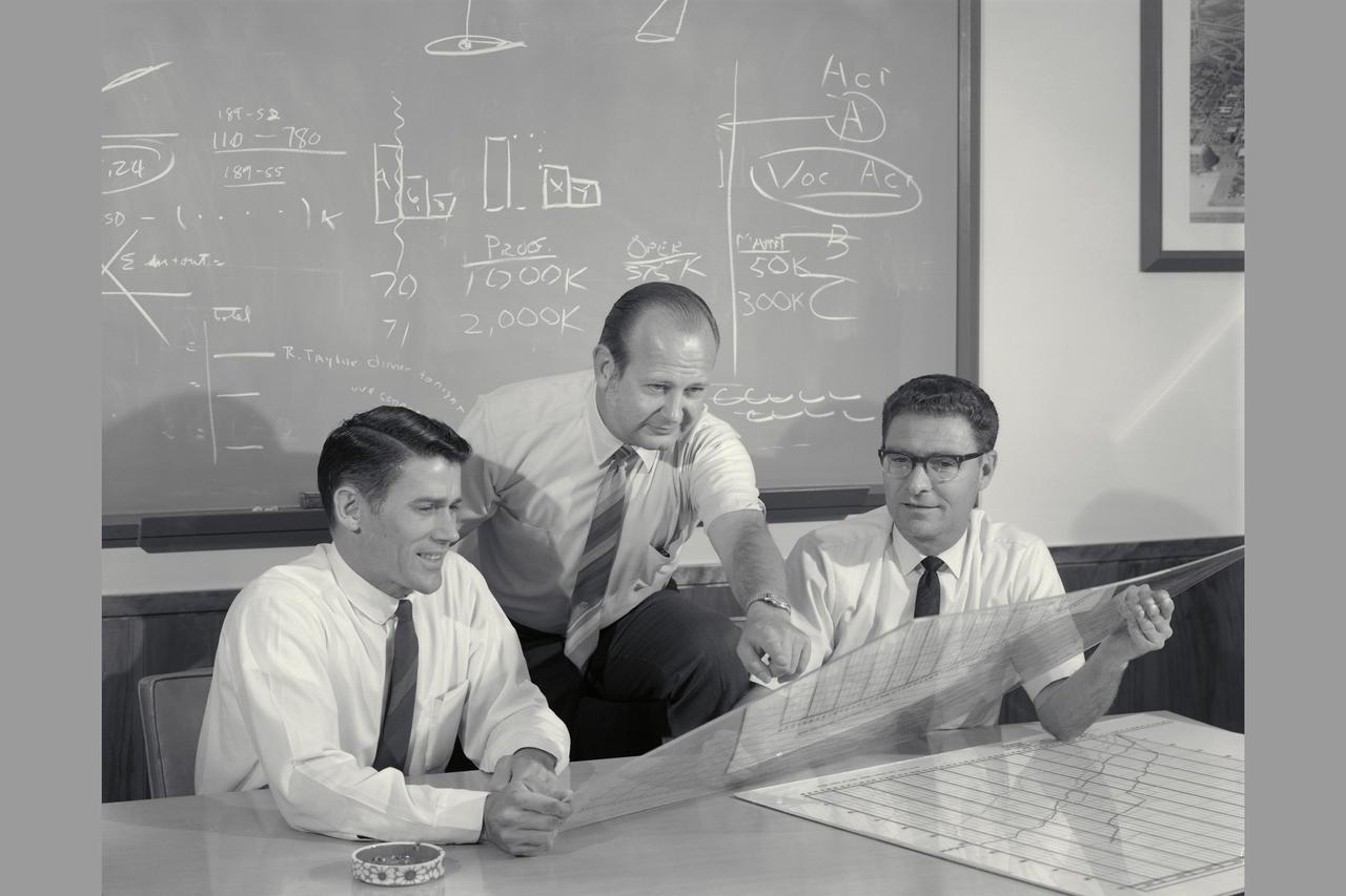
Ames engineers Allen Faye, Merrill Mead and John 'Jack' Boyd discuss aircraft design and handling

A C-17 Globemaster aircraft from the Alaska Air National Guard’s 249th Airlift Squadron flies overhead as pararescue specialists from the 304th Rescue Squadron, located in Portland, Oregon complete an astronaut rescue training exercise inside a covered life raft on the Atlantic Ocean. The pararescue specialists, supporting the 45th Operations Group’s Detachment 3, based out of Patrick Air Force Base, conducted the exercise in April with NASA’s Commercial Crew Program and SpaceX off of Florida’s eastern coast. The specially designed 20-person life raft is equipped with enough food, water and medical supplies to sustain both rescuers and crew for up to three days, if necessary. In this situation, the Department of Defense (DOD) would complete the rescue by enlisting help from the US Coast Guard, a DOD ship, or a nearby commercial ship of opportunity to transport the crew to safety.
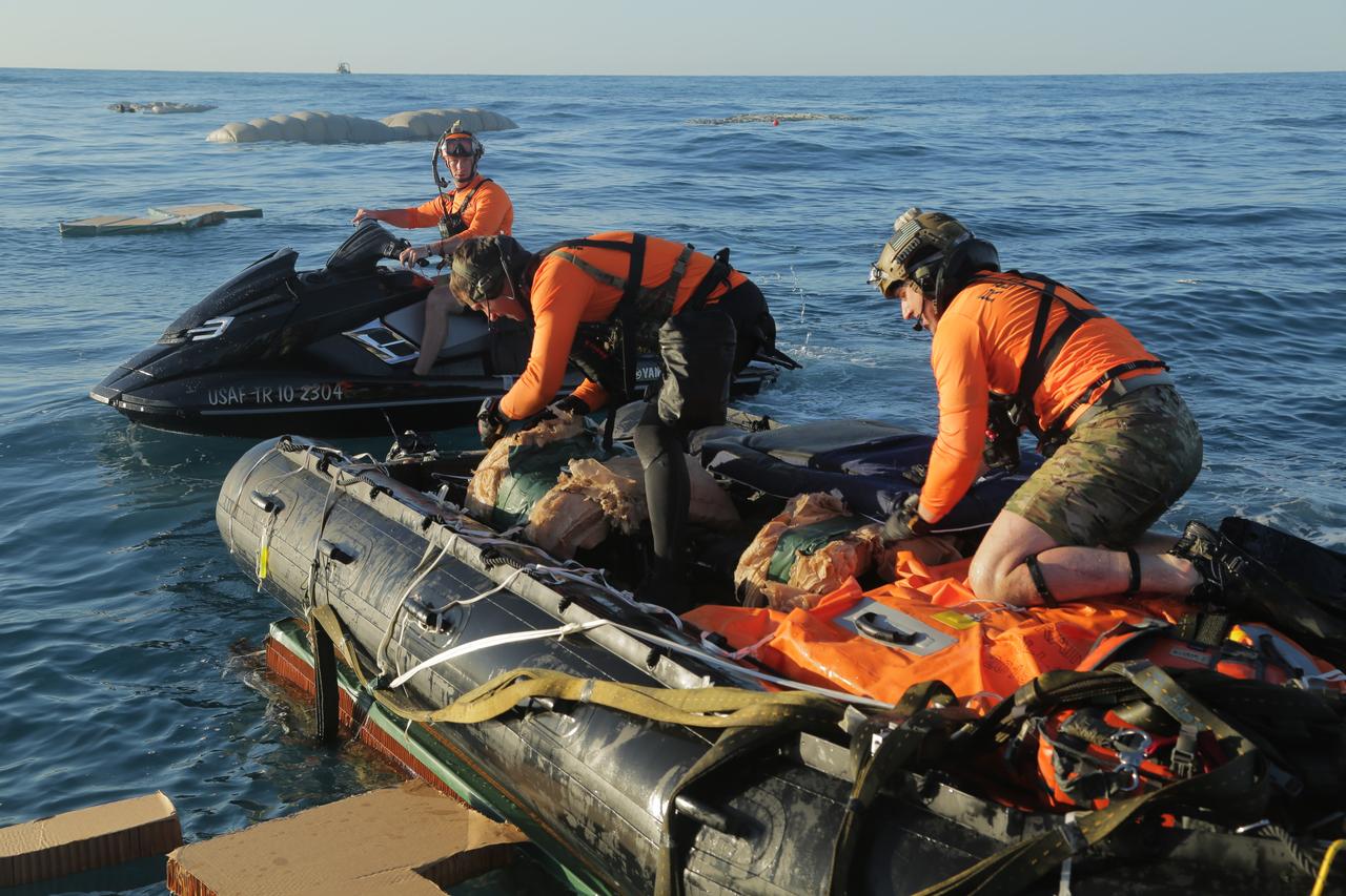
Pararescue specialists from the 304th Rescue Squadron, located in Portland, Oregon and supporting the 45th Operations Group’s Detachment 3, based out of Patrick Air Force Base, prepare equipment during an April astronaut rescue exercise with NASA’s Commercial Crew Program and SpaceX off of Florida’s eastern coast. The pararescue specialists, also known as “Guardian Angels,” jumped from military aircraft and simulated a rescue operation to demonstrate their ability to safely remove crew from the SpaceX Crew Dragon in the unlikely event of an emergency landing. The pararescue specialists are fully qualified paramedics able to perform field surgery, if necessary.
51F-13-021 (29 July-6 Aug 1985) --- Astronaut Story Musgrave, STS51F mission specialist, is seen hitching a zero-g ride on a blood centrifuge on the middeck of the space shuttle Challenger. "The centrifuge got more workout than just separation of our blood," crewmate John Bartoe, payload specialist, later told a gathering of media representatives at the 51F post-flight press conference, referring to Musgrave's off-duty antics. Photo credit: NASA
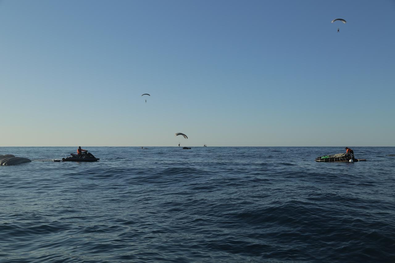
Pararescue specialists from the 304th Rescue Squadron, located in Portland, Oregon and supporting the 45th Operations Group’s Detachment 3, based out of Patrick Air Force Base, deploy their parachutes and prepare to touch down on the Atlantic Ocean surface during an April astronaut rescue exercise with NASA’s Commercial Crew Program and SpaceX off of Florida’s eastern coast. The pararescue specialists, also known as “Guardian Angels,” jumped from military aircraft and simulated a rescue operation to demonstrate their ability to safely remove crew from the SpaceX Crew Dragon in the unlikely event of an emergency landing.

Pararescue specialists from the 304th Rescue Squadron, located in Portland, Oregon and supporting the 45th Operations Group’s Detachment 3, based out of Patrick Air Force Base, secure a covered life raft as the sun sets during an astronaut rescue training exercise with NASA’s Commercial Crew Program and SpaceX off of Florida’s eastern coast in April. The specially designed 20-person life raft is equipped with enough food, water and medical supplies to sustain both rescuers and crew for up to three days, if necessary. In this situation, the Department of Defense (DOD) would complete the rescue by enlisting help from the US Coast Guard, a DOD ship, or a nearby commercial ship of opportunity to transport the crew to safety.
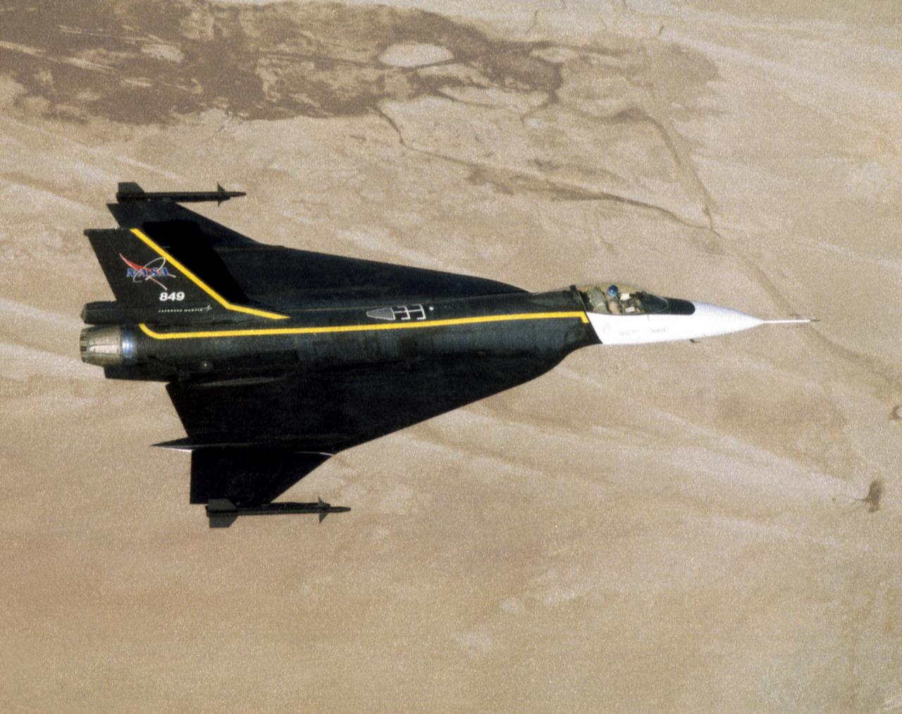
An image of the F-16XL #1 during its functional flight check of the Digital Flight Control System (DFCS) on December 16, 1997. The mission was flown by NASA research pilot Dana Purifoy, and lasted 1 hour and 25 minutes. The tests included pilot familiarly, functional check, and handling qualities evaluation maneuvers to a speed of Mach 0.6 and 300 knots. Purifoy completed all the briefed data points with no problems, and reported that the DFCS handled as well, if not better than the analog computer system that it replaced.

Presented here are side-by-side comparisons of a traditional Cassini Synthetic Aperture Radar (SAR) view and one made using a new technique for handling electronic noise that results in clearer views of Titan's surface. The technique, called despeckling, produces images that can be easier for researchers to interpret. The view is a mosaic of SAR swaths over Ligeia Mare, one of the large hydrocarbons seas on Titan. In particular, despeckling improves the visibility of channels flowing down to the sea. http://photojournal.jpl.nasa.gov/catalog/PIA19052

How differential deflection of the inboard and outboard leading-edge flaps affected the handling qualities of this modified F/A-18A was evaluated during the first check flight in the Active Aeroelastic Wing program at NASA's Dryden Flight Research Center.
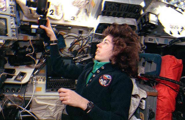
Space Shuttle Discovery (STS-56) Mission Specialist 3 (MS3) Ellen Ochoa handles a 35mm camera on the aft flight deck of the Orbiter. Ochoa is positioned next to the payload station and behind the commander's station.
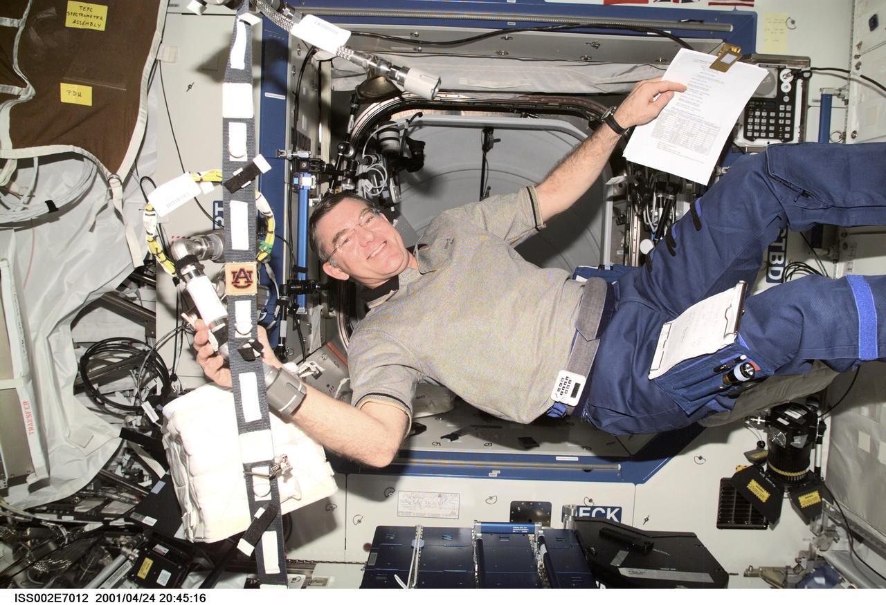
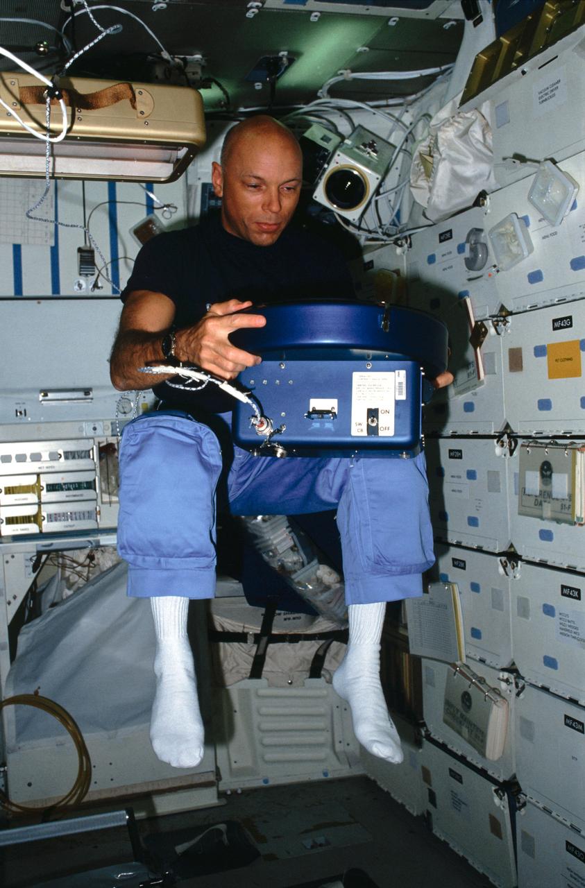
ISS002-E-7012 (24 April 2001) --- Astronaut James S. Voss, Expedition Two flight engineer, handles a connector in the Destiny/U.S. Laboratory. A digital still camera was used to record this image.
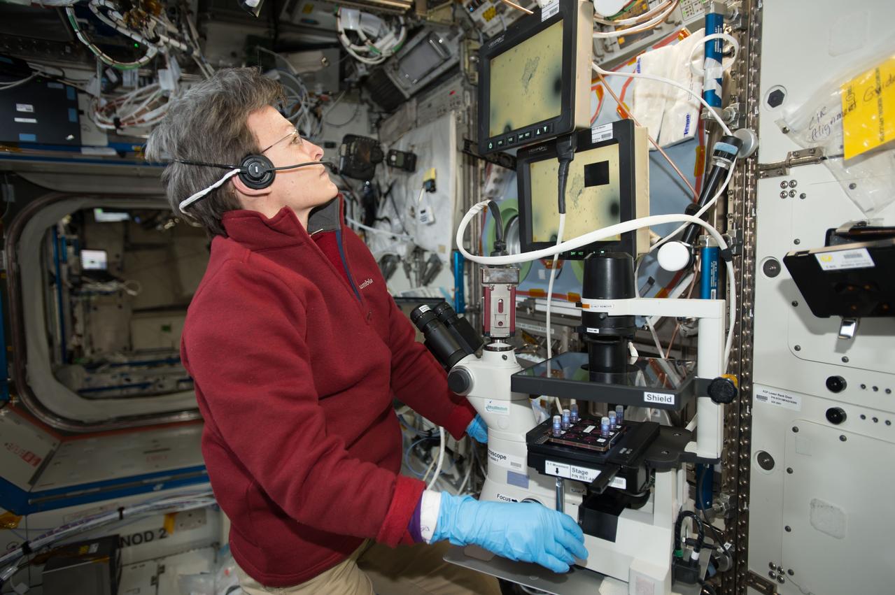
iss052e014201 (7/11/2017) --- NASA astronaut Peggy Whitson uses a microscope to view Magnetic 3D Biocells. This investigation uses magnetized cells and tools to make it easier to handle cells and cultures and to improve the reproducibility of experiments.
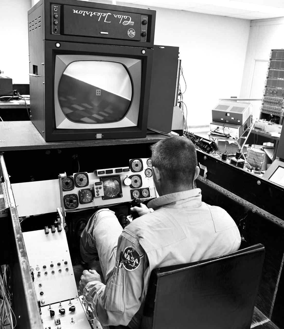
As shown in this photo of the HL-10 flight simulator, the lifting-body pilots and engineers made use of early simulators for both training and the determination of a given vehicle's handling at various speeds, attitudes, and altitudes. This provided warning of possible problems.
STS105-E-5414 (20 August 2001) --- Astronaut Frederick W. Sturckow, STS-105 pilot, handles the Co-Axial Sight (COAS) on the mid deck of the Space Shuttle Discovery. This image was taken with a digital still camera.
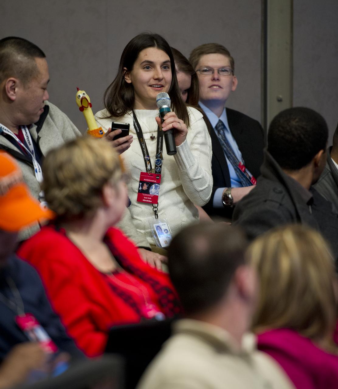
NASA Twitter follower Sarah Smith, Twitter handle @smith5se, asks a question at a Tweetup hosted by astronaut Ron Garan at NASA Headquarters in Washington, Tuesday, Feb. 14, 2012. Photo Credit: (NASA/Carla Cioffi)
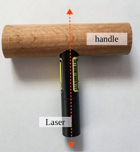
jsc2021e037886 (8/242021) --- A preflight photo of the First object to be observed rotating around its intermediate axis, made from a laser-pointer and a wooden handle for the Dzhanibekov Demonstrations investigation. Image courtesy of DLR.
jsc2021e012558 (12/2021) --- NASA astronaut Shannon Walker, handling the fiber produced by the second iteration of FOP hardware (FOP1.5) during the ISS demo in December 2020. Image courtesy of Physical Optics Corporation.
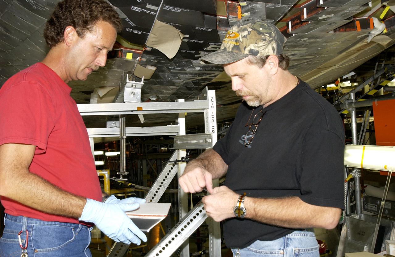
In the Vehicle Assembly Building, Jim Landy, NDE specialist, sets up a flight crew lockers for flash thermography. He is screening the lockers for hidden damage underneath dings and dents that might occur during handling.
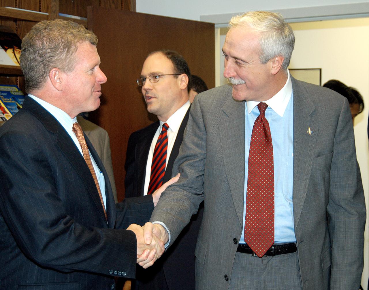
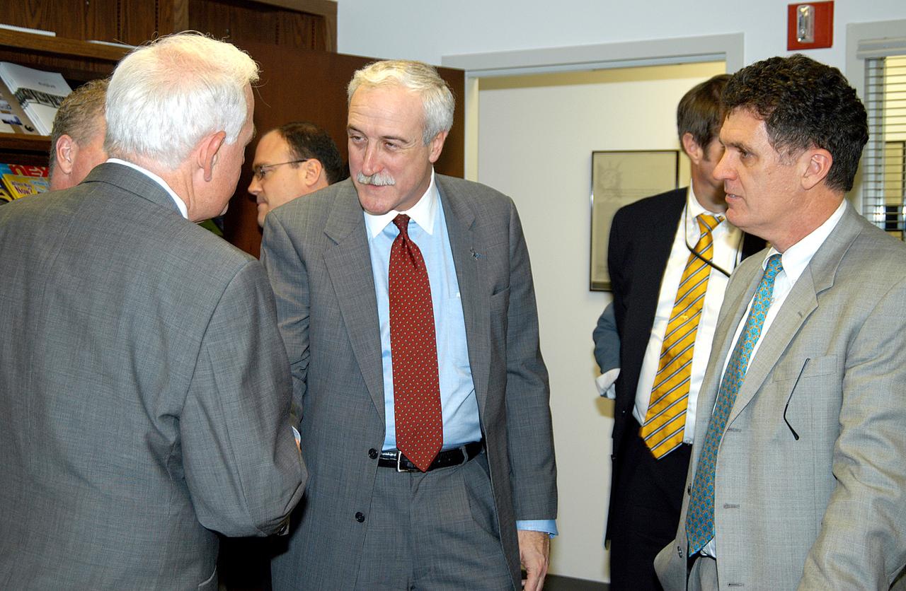
KENNEDY SPACE CENTER, FLA. - NASA Administrator Sean O’Keefe (right) greets Florida Congressman Tom Feeney during a tour of the Central Florida Research Park, near Orlando. Central Florida leaders are proposing the research park as the site for the new NASA Shared Services Center. The center would centralize NASA’s payroll, accounting, human resources, facilities and procurement offices that are now handled at each field center. The consolidation is part of the One NASA focus. Six sites around the U.S. are under consideration by NASA.
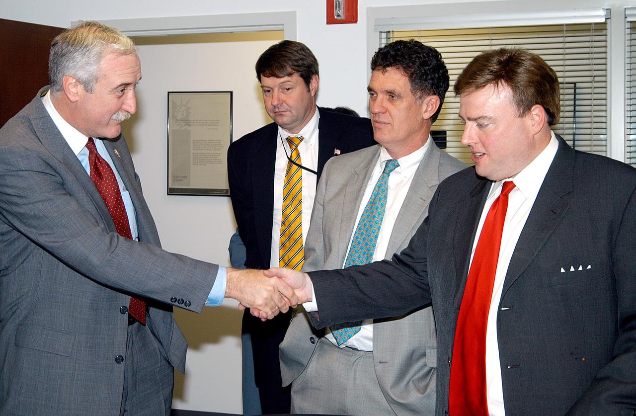
KENNEDY SPACE CENTER, FLA. - NASA Administrator Sean O’Keefe (left) greets U.S. Representative Ric Keller during a tour of the Central Florida Research Park, near Orlando. Central Florida leaders are proposing the research park as the site for the new NASA Shared Services Center. The center would centralize NASA’s payroll, accounting, human resources, facilities and procurement offices that are now handled at each field center. The consolidation is part of the One NASA focus. Six sites around the U.S. are under consideration by NASA.
KENNEDY SPACE CENTER, FLA. - NASA Administrator Sean O’Keefe (center) is welcomed to the Central Florida Research Park, near Orlando. Central Florida leaders are proposing the research park as the site for the new NASA Shared Services Center. The center would centralize NASA’s payroll, accounting, human resources, facilities and procurement offices that are now handled at each field center. The consolidation is part of the One NASA focus. Six sites around the U.S. are under consideration by NASA.
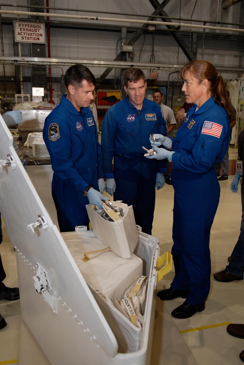
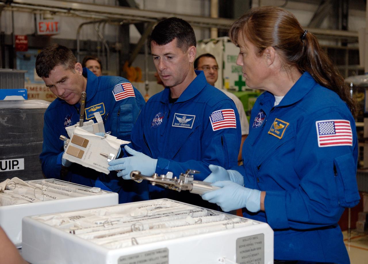
CAPE CANAVERAL, Fla. – In Orbiter Processing Facility 2 at NASA's Kennedy Space Center, STS-126 Mission Specialists (from left) Steve Bowen, Shane Kimbrough and Heidemarie Stefanyshyn-Piper handle tools required for the mission. Members of space shuttle Endeavour's STS-126 crew are at Kennedy to participate in a crew equipment interface test, or CEIT. The CEIT provides experience handling tools, equipment and hardware they will use on the mission. Endeavour will deliver a multi-purpose logistics module to the International Space Station on the STS-126 mission. Launch is targeted for Nov. 10. Photo credit: NASA/Kim Shiflett
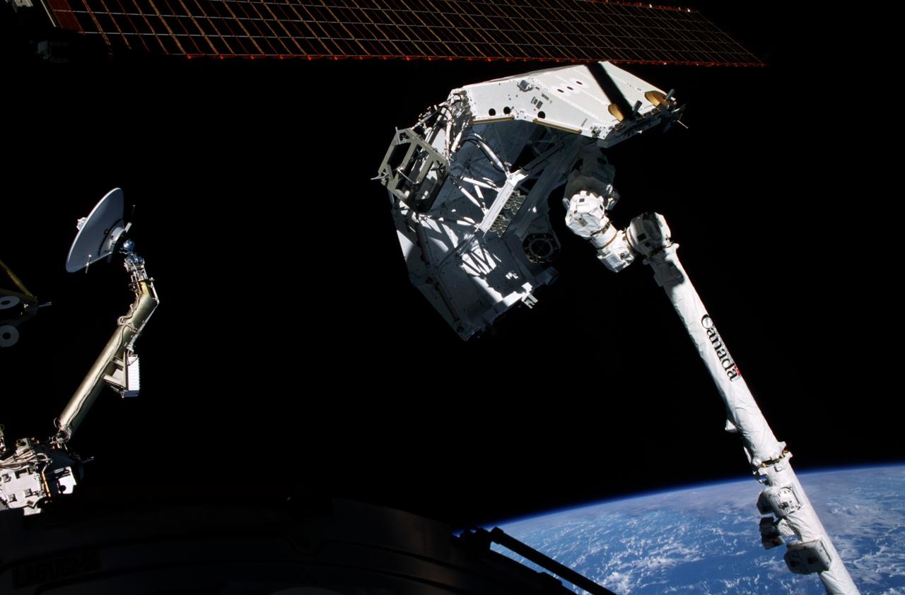
A worker in the Payload Changeout Room, Launch Pad 39A, moves the Payload Ground Handling Mechanism away from the open doors of Space Shuttle Endeavour’s payload bay. The PGHM helped move the STS-100 mission payload into the bay. Visible above and behind the worker is the Multi-Purpose Logistics Module Raffaello, which carries six system racks and two storage racks for the U.S. Lab. Above Raffaello is the Canadian robotic arm, the SSRMS. Capable of handling large payloads and assisting with docking the Space Shuttle, the SSRMS is crucial to the continued assembly of the International Space Station. Launch of mission STS-100 is scheduled for April 19 at 2:41 p.m. EDT
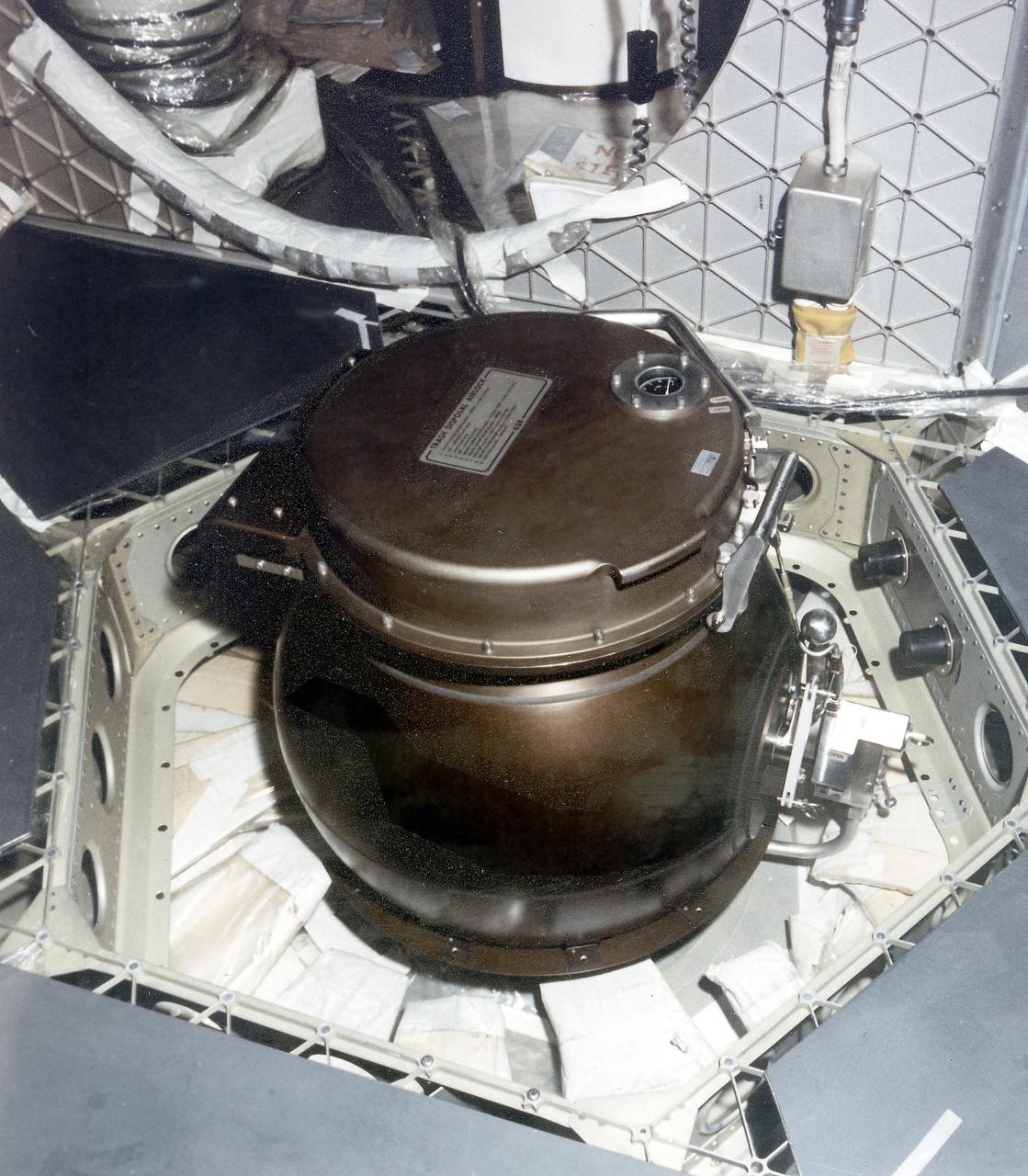
This is a close-up photograph of the Orbital Workshop (OWS) trash disposal airlock located on the floor of the lower level of the OWS. It provided a means of passing trash from the pressurized habitable area into the unpressurized waste tank. The crewman opened a valve which brought the airlock to the same pressure as that within the workshop. He then opened the lid, placed the bagged trash inside, closed the lid and locked it. By turning the valve handle, he reduced the pressure within the airlock until it reached the vacuum of the waste tank. The crewman then operated an ejector handle that caused a scissors-type mechanism to push the bagged trash from the airlock into the tank.
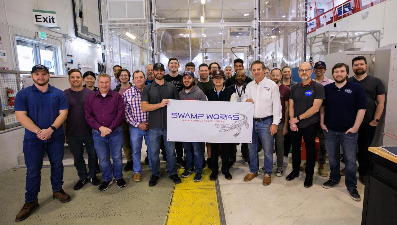
Groups from the Granular Mechanics and Regolith Operations (GMRO) laboratory and the Electrostatics and Surface Physics Laboratory (ESPL) gather for a photograph to celebrate the 10th anniversary of Swamp Works at NASA’s Kennedy Space Center in Florida on Feb. 13, 2023. Studies of the mechanics of materials in a launch pad environment are performed in the GMRO lab. The team also develops technologies for handling lunar and Martian regolith, including excavator technologies, pneumatic transport of soil, and magnetic handling of soil. The ESPL group performs scientific investigations to protect flight hardware and launch equipment from the phenomenon of electrostatic discharges, commonly known as sparks.
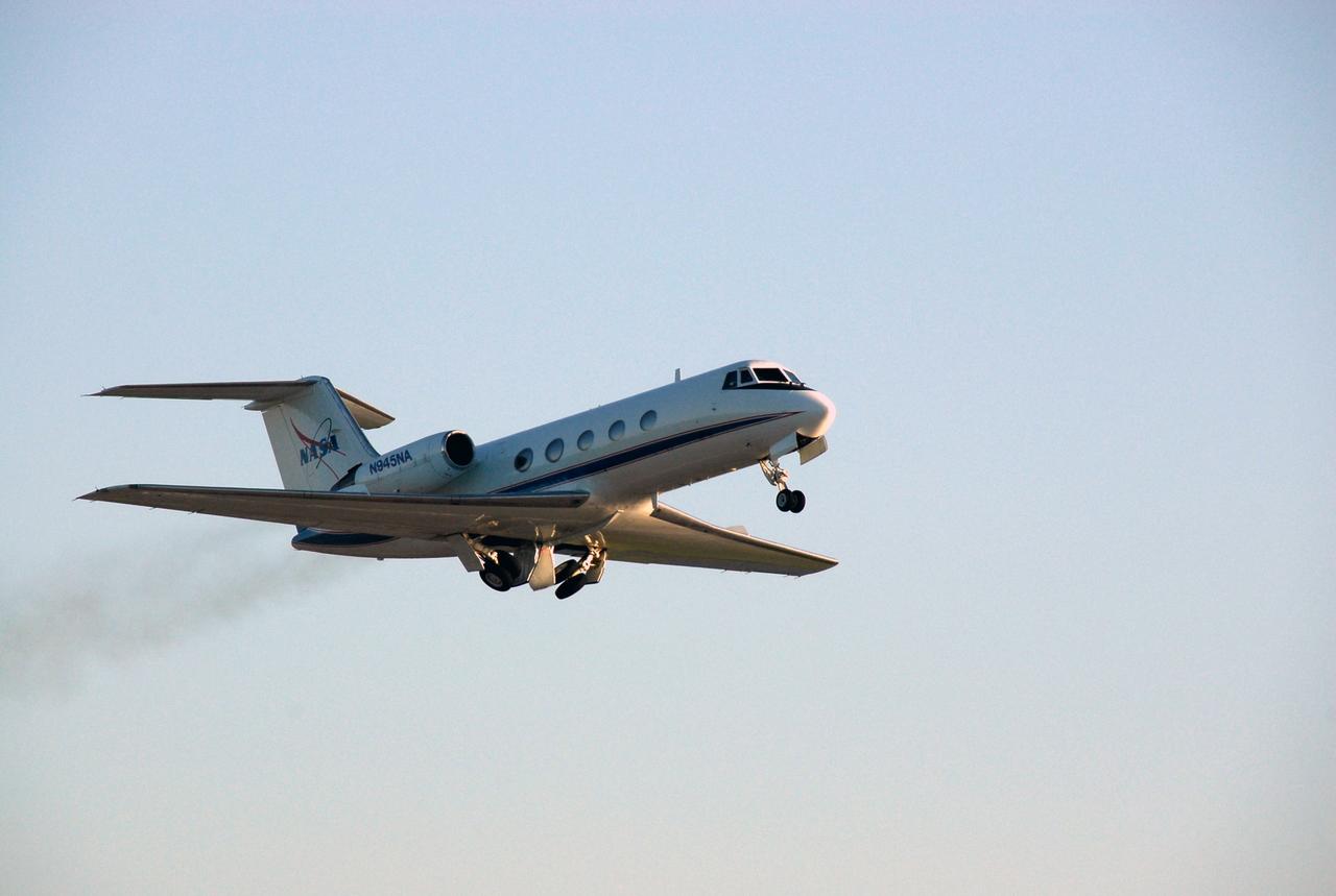
CAPE CANAVERAL, Fla. -- One of the shuttle training aircraft, or STA, takes off from the runway at NASA Kennedy Space Center's Shuttle Landing Facility. Handling the controls is the pilot of the STS-124 mission, Ken Ham, who will practice landing the shuttle. The STA is a Grumman American Aviation-built Gulf Stream II jet that was modified to simulate an orbiter's cockpit, motion and visual cues, and handling qualities. In flight, the aircraft duplicates the orbiter's atmospheric descent trajectory from approximately 35,000 feet altitude to landing on a runway. Space shuttle Discovery is scheduled to lift off on the STS-124 mission at 5:02 p.m. May 31. Photo credit: NASA/Kim Shiflett
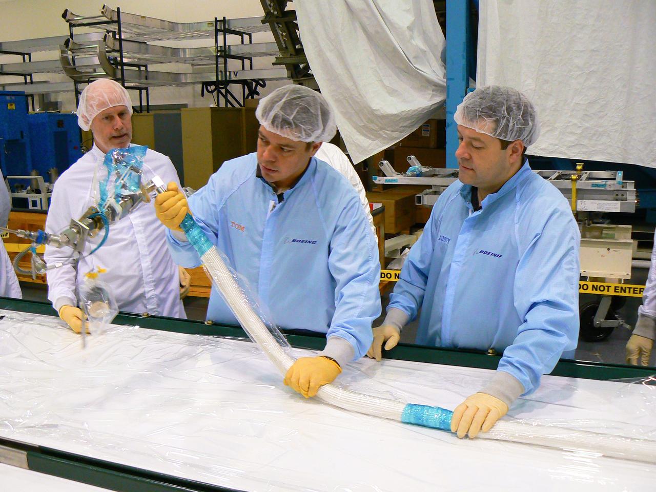
JSC2010-E-014775 (15 Jan. 2010) --- Seen at Marshall Space Center building 4708 in the high-bay clean room, astronauts Nicholas Patrick (right) and Robert Behnken, both STS-130 mission specialists, accompanied by Eric Howell, Boeing Huntsville Chief Engineer for ISS, handle ammonia hoses to be installed during mission STS-130. The hoses are at 500 pounds per square inch pressure (psi) to give them a feel for how stiff the hoses would be at 500 psi if they had to handle them under pressure on orbit.
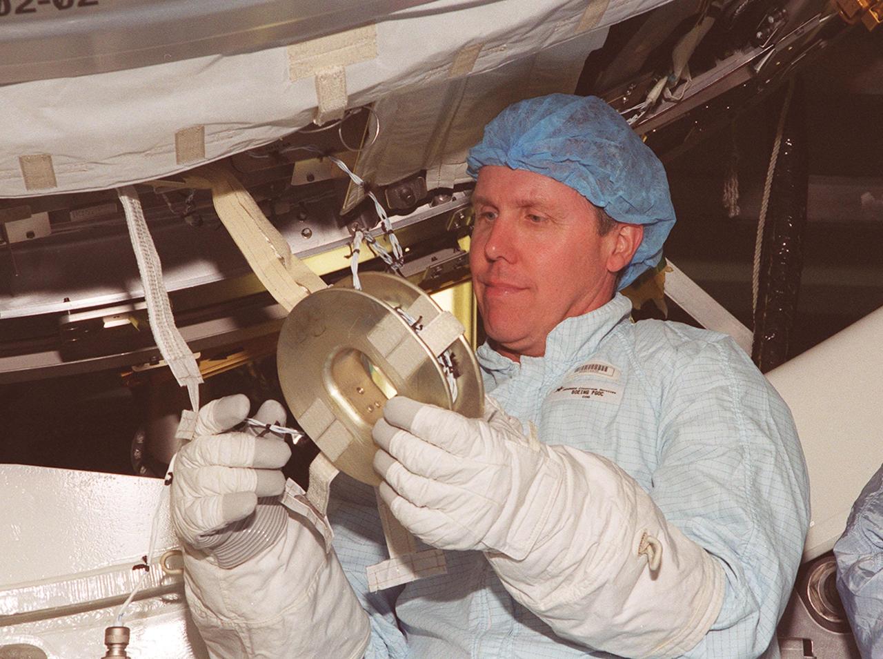
STS-98 Mission Specialist Thomas Jones practices handling a piece of equipment on the U.S. Lab, Destiny, while wearing the gloves he will wear in space. Jones and other crew members are taking part in Crew Equipment Interface Test activities to become familiar with equipment they will be handling during the mission. With launch scheduled for Jan. 18, 2001, the STS-98 mission will be transporting the Lab to the International Space Station with five system racks already installed inside of the module. After delivery of electronics in the lab, electrically powered attitude control for Control Moment Gyroscopes will be activated
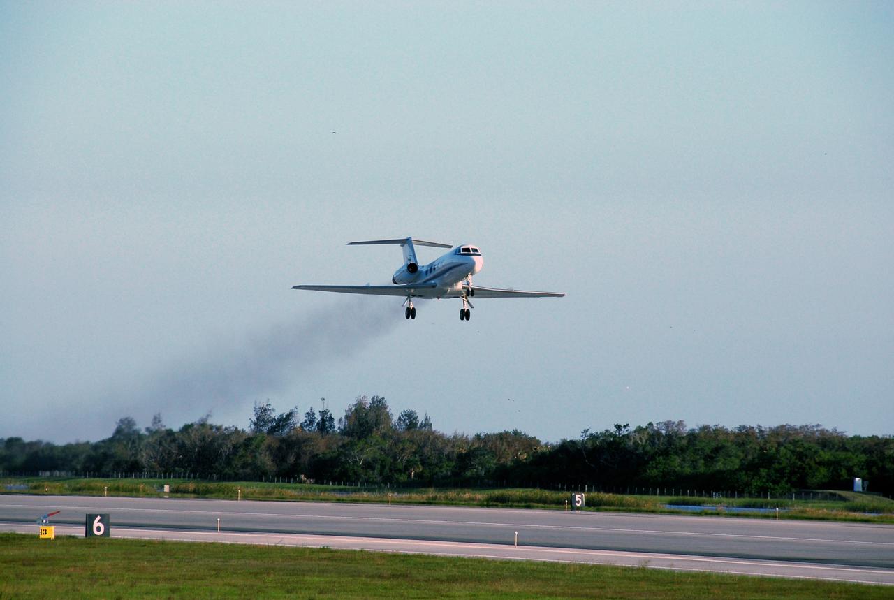
CAPE CANAVERAL, Fla. -- One of the shuttle training aircraft, or STA, takes off from the runway at NASA Kennedy Space Center's Shuttle Landing Facility. Handling the controls is the commander of the STS-124 mission, Mark Kelly, who will practice landing the shuttle. The STA is a Grumman American Aviation-built Gulf Stream II jet that was modified to simulate an orbiter's cockpit, motion and visual cues, and handling qualities. In flight, the aircraft duplicates the orbiter's atmospheric descent trajectory from approximately 35,000 feet altitude to landing on a runway. Space shuttle Discovery is scheduled to lift off on the STS-124 mission at 5:02 p.m. May 31. Photo credit: NASA/Kim Shiflett
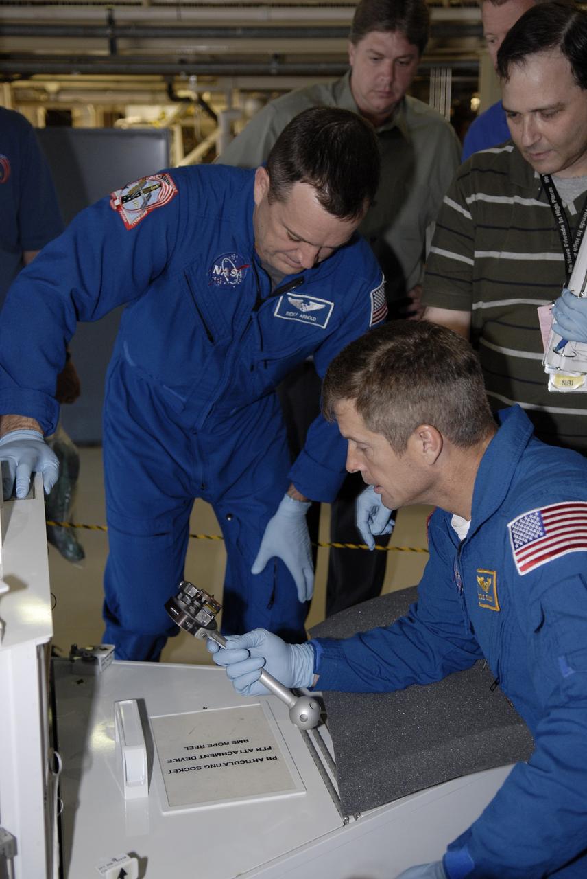
CAPE CANAVERAL, Fla. -- In the Orbiter Processing Facility at NASA's Kennedy Space Center in Florida, STS-119 Mission specialists Richard Arnold (left) and Steve Swanson handle tools to be used on the mission. The crew is at Kennedy for a Crew Equipment Interface Test that provides experience handling tools, equipment and hardware they will use on the mission. On the STS-119 mission, space shuttle Discovery will carry the S6 truss segment to complete the 361-foot-long backbone of the International Space Station. The truss includes the fourth pair of solar array wings and electronics that convert sunlight to power for the orbiting laboratory. Discovery is targeted for launch on Feb. 12, 2009. Photo credit: NASA/Kim Shiflett
CAPE CANAVERAL, Fla. – In Orbiter Processing Facility 2 at NASA's Kennedy Space Center, STS-126 Mission Specialists (from left) Steve Bowen, Shane Kimbrough and Heidemarie Stefanyshyn-Piper handle tools required for the mission. Members of space shuttle Endeavour's STS-126 crew are at Kennedy to participate in a crew equipment interface test, or CEIT. The CEIT provides experience handling tools, equipment and hardware they will use on the mission. Endeavour will deliver a multi-purpose logistics module to the International Space Station on the STS-126 mission. Launch is targeted for Nov. 10. Photo credit: NASA/Kim Shiflett

JSC2003-E-42548 (For Release: 18 June 2003) --- The Remote Manipulator System (RMS) Small Fine Arm is shown in a processing facility. The RMS consists of two robotic arms that support operations on the outside of the Japanese Experiment Module (JEM) Japan's primary contribution to the International Space Station. The Main Arm can handle up to seven tons (14,000 pounds) of hardware and the Small Fine Arm, when attached to the Main Arm, handles more delicate operations. Each arm has six joints that mimic the movements of a human arm. Photo Credit: NASA
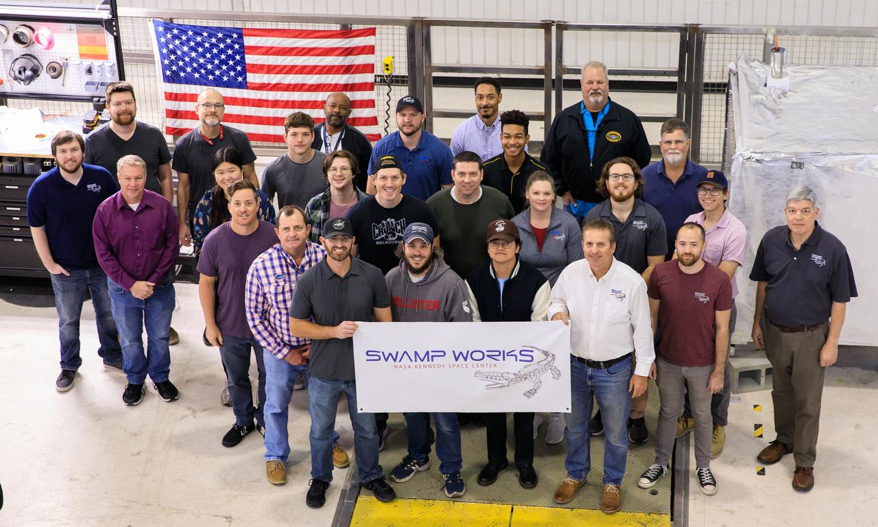
Groups from the Granular Mechanics and Regolith Operations (GMRO) laboratory and the Electrostatics and Surface Physics Laboratory (ESPL) gather for a photograph to celebrate the 10th anniversary of Swamp Works at NASA’s Kennedy Space Center in Florida on Feb. 13, 2023. Studies of the mechanics of materials in a launch pad environment are performed in the GMRO lab. The team also develops technologies for handling lunar and Martian regolith, including excavator technologies, pneumatic transport of soil, and magnetic handling of soil. The ESPL group performs scientific investigations to protect flight hardware and launch equipment from the phenomenon of electrostatic discharges, commonly known as sparks.
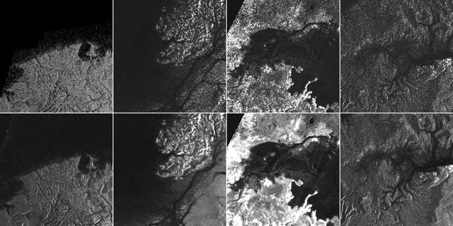
This montage of Cassini Synthetic Aperture Radar (SAR) images of the surface of Titan shows four examples of how a newly developed technique for handling noise results in clearer, easier to interpret views. The top row of images was produced in the manner used since the mission arrived in the Saturn system a decade ago; the row at bottom was produced using the new technique. The three leftmost image pairs show bays and spits of land in Ligea Mare, one of Titan's large hydrocarbon seas. The rightmost pair shows a valley network along Jingpo Lacus, one of Titan's larger northern lakes. North is toward the left in these images. Each thumbnail represents an area 70 miles (112 kilometers) wide. http://photojournal.jpl.nasa.gov/catalog/PIA19053
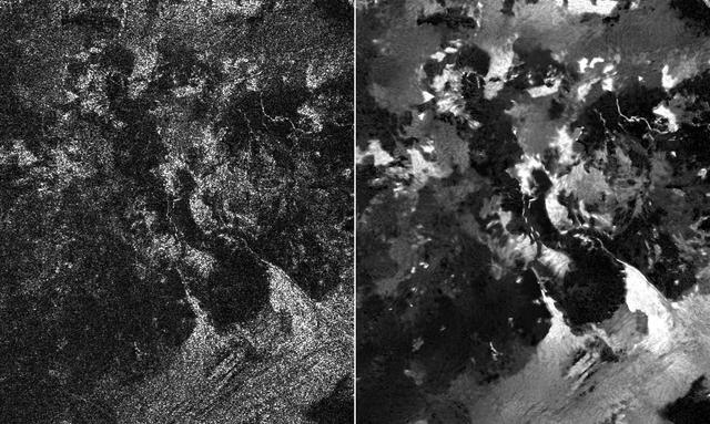
Presented here are side-by-side comparisons of a traditional Cassini Synthetic Aperture Radar (SAR) view, at left, and one made using a new technique for handling electronic noise that results in clearer views of Titan's surface, at right. The technique, called despeckling, produces images that can be easier for researchers to interpret. The terrain seen here is in the flow region named Leilah Fluctus (55 degrees north, 80 degrees west). With the speckle noise suppressed, the overall pattern of bright and dark in the scene becomes more apparent. In particular, cone-shaped features near lower right stand out, which could be alluvial analogues on Titan -- features produced by the action of rivers or floods. North is toward right in this image, which shows an area about 50 miles (80 kilometers) wide. http://photojournal.jpl.nasa.gov/catalog/PIA19054
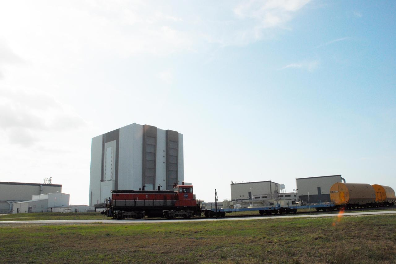
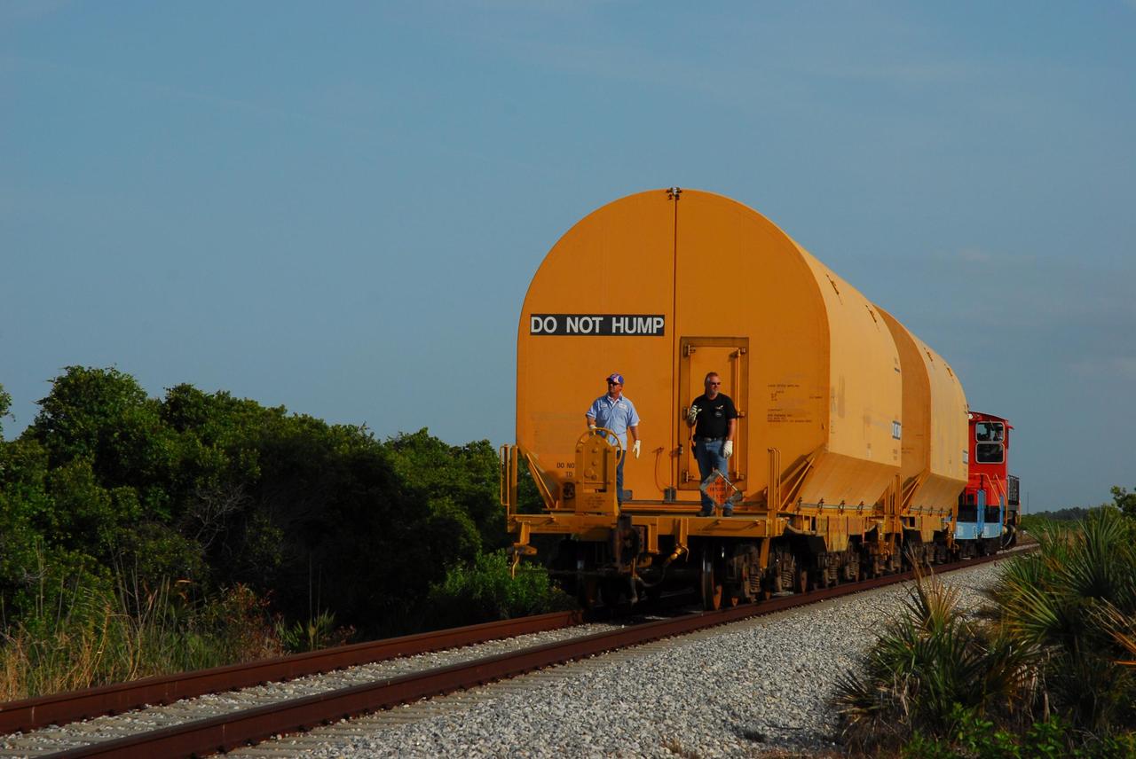
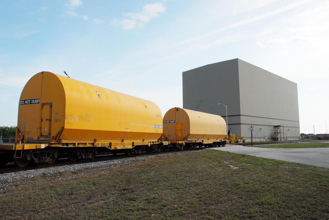
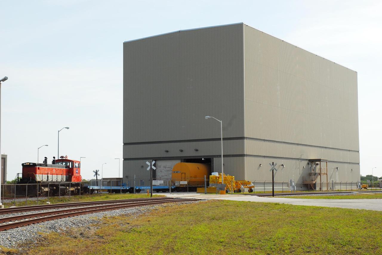
KENNEDY SPACE CENTER, FLA. -- The locomotive and rail cars carrying solid rocket booster motor segments and two aft exit cone segments roll past the Vehicle Assembly Building to the Rotation, Processing and Surge Facility (RPSF) in Kennedy Space Center's Launch Complex 39 Area. The RPSF is used for solid rocket motor receiving, rotation and inspection, and supports aft booster buildup. When live solid rocket motor segments arrive at the processing facility, they are positioned under one of the cranes. Handling slings are then attached to and remove the railcar cover. The segment is inspected while it remains horizontal. The two overhead cranes hoist the segment, rotate it to a vertical position and place it on a fixed stand. The aft handling ring is then removed. The segment is hoisted again and lowered onto a transportation and storage pallet, and the forward handling ring is removed to allow inspections. It is then transported to one of the surge buildings and temporarily stored until it is needed for booster stacking in the VAB. While enroute, solid rocket motor segments were involved in a derailment in Alabama. The rail cars carrying these segments remained upright and were undamaged. An inspection determined these segment cars could continue on to Florida. The segments themselves will undergo further evaluation at Kennedy before they are cleared for flight. Other segments involved in the derailment will be returned to a plant in Utah for further evaluation. Photo credit: NASA/George Shelton
KENNEDY SPACE CENTER, FLA. -- The locomotive and rail cars carrying solid rocket booster motor segments and two aft exit cone segments roll to the Rotation, Processing and Surge Facility in Kennedy Space Center's Launch Complex 39 Area. The main facility is used for solid rocket motor receiving, rotation and inspection, and supports aft booster buildup. When live solid rocket motor segments arrive at the processing facility, they are positioned under one of the cranes. Handling slings are then attached to and remove the railcar cover. The segment is inspected while it remains horizontal. The two overhead cranes hoist the segment, rotate it to a vertical position and place it on a fixed stand. The aft handling ring is then removed. The segment is hoisted again and lowered onto a transportation and storage pallet, and the forward handling ring is removed to allow inspections. It is then transported to one of the surge buildings and temporarily stored until it is needed for booster stacking in the VAB. While enroute, solid rocket motor segments were involved in a derailment in Alabama. The rail cars carrying these segments remained upright and were undamaged. An inspection determined these segment cars could continue on to Florida. The segments themselves will undergo further evaluation at Kennedy before they are cleared for flight. Other segments involved in the derailment will be returned to a plant in Utah for further evaluation. Photo credit: NASA/George Shelton
KENNEDY SPACE CENTER, FLA. -- The locomotive and rail cars carrying solid rocket booster motor segments and two aft exit cone segments roll toward the Rotation, Processing and Surge Facility (RPSF) in Kennedy Space Center's Launch Complex 39 Area. The RPSF is used for solid rocket motor receiving, rotation and inspection, and supports aft booster buildup. When live solid rocket motor segments arrive at the processing facility, they are positioned under one of the cranes. Handling slings are then attached to and remove the railcar cover. The segment is inspected while it remains horizontal. The two overhead cranes hoist the segment, rotate it to a vertical position and place it on a fixed stand. The aft handling ring is then removed. The segment is hoisted again and lowered onto a transportation and storage pallet, and the forward handling ring is removed to allow inspections. It is then transported to one of the surge buildings and temporarily stored until it is needed for booster stacking in the VAB. While enroute, solid rocket motor segments were involved in a derailment in Alabama. The rail cars carrying these segments remained upright and were undamaged. An inspection determined these segment cars could continue on to Florida. The segments themselves will undergo further evaluation at Kennedy before they are cleared for flight. Other segments involved in the derailment will be returned to a plant in Utah for further evaluation. Photo credit: NASA_George Shelton
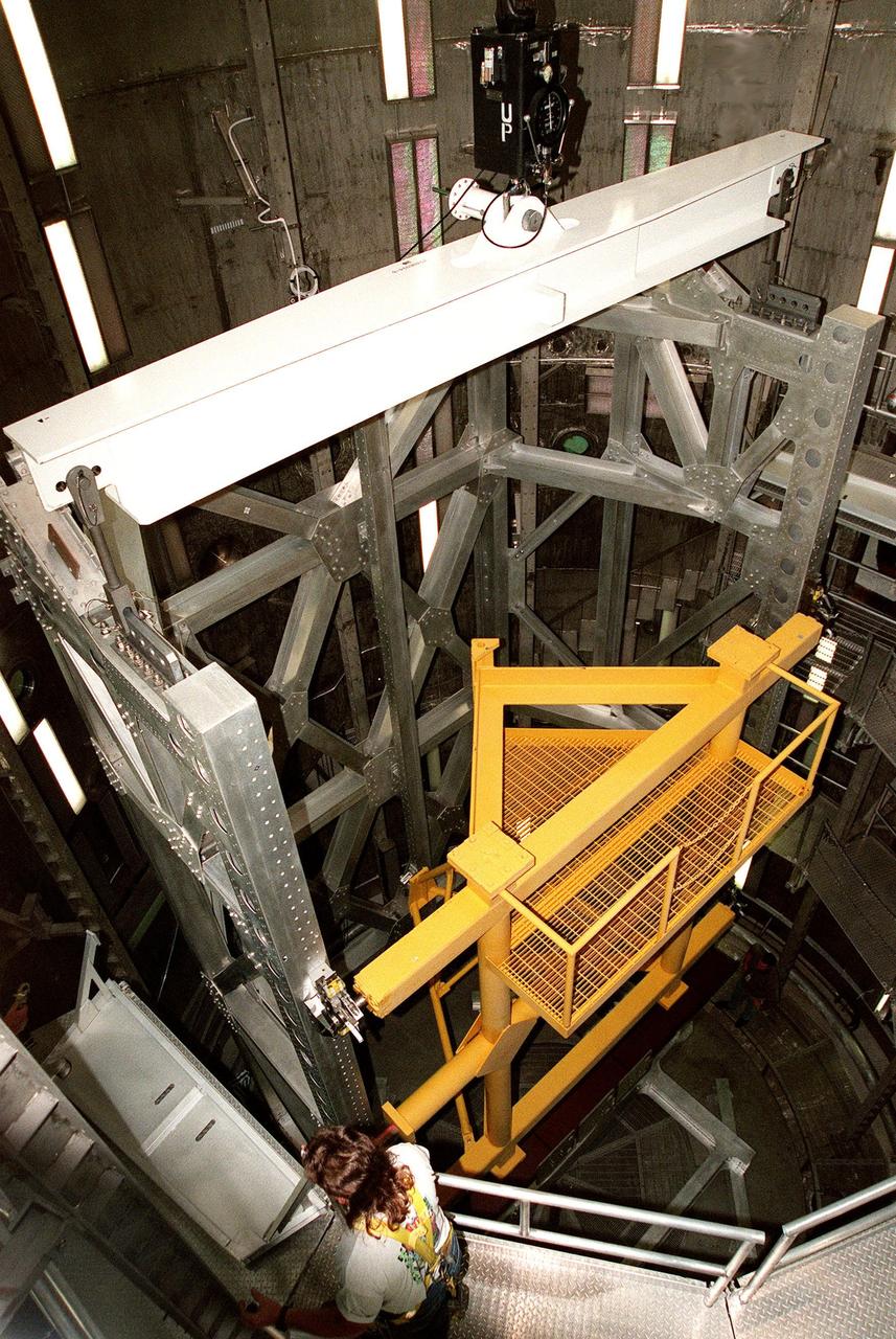
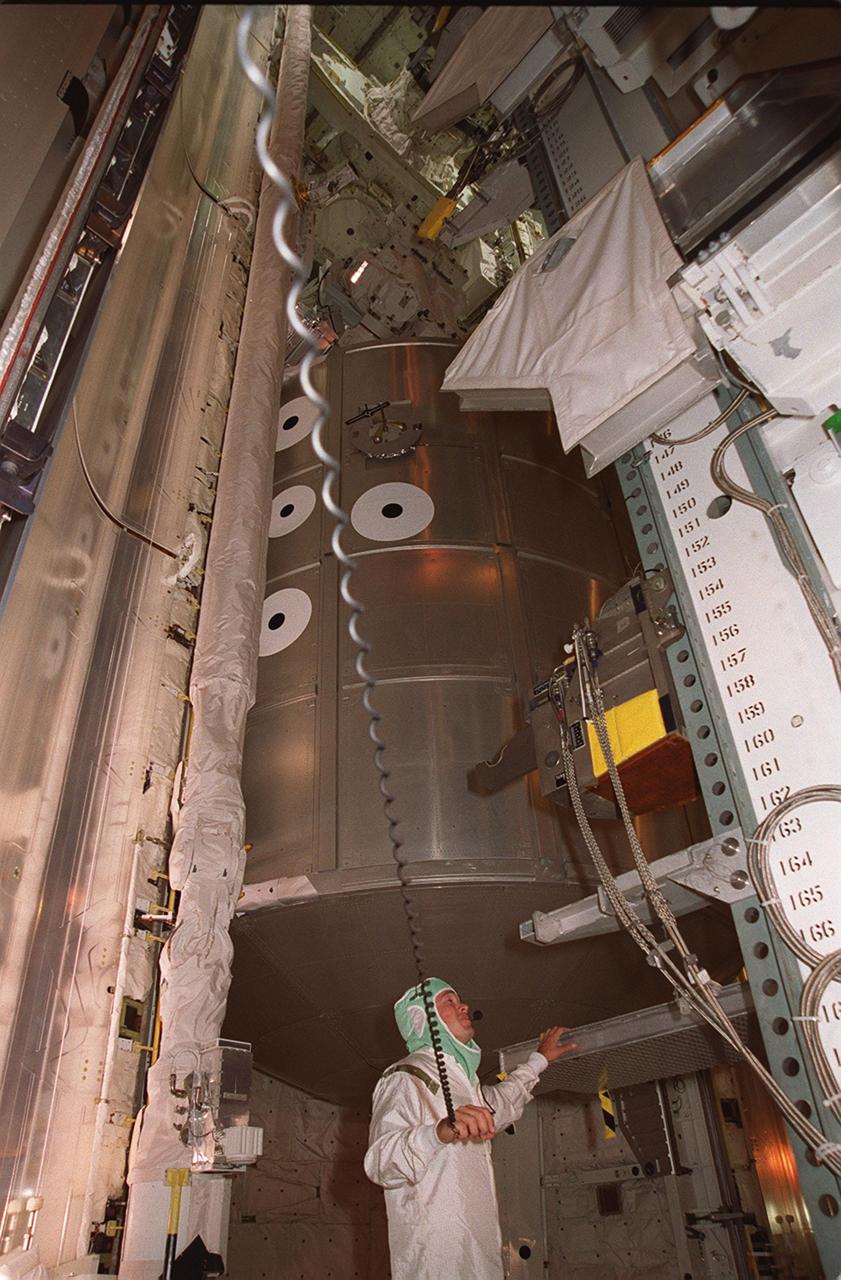
KENNEDY SPACE CENTER, FLA. -- In the Operations and Checkout Building's high bay, the Rotation Handling Fixture (RHF), with a simulated module attached, is viewed from above the altitude chamber into which it was lowered during a test. Under normal operation, the RHF will hold a pressurized module intended for the International Space Station, depositing it into the altitude chamber for leak testing. The chamber was recently reactivated after a 20-year hiatus. Originally, two chambers were built to test Apollo Program flight hardware. They were last used in 1975 during the Apollo-Soyuz Test Project. In 1997, in order to increase the probability of successful missions aboard the ISS, NASA decided to perform leak tests on ISS pressurized modules at the launch site. After installation of new vacuum pumping equipment and controls, a new control room, and a new rotation and handling fixture, the chamber again became operational in February 1999. The chamber, which is 33 feet in diameter and 50 feet tall, is constructed of stainless steel. The rotation handling fixture is aluminum. The first module that will be tested for leaks is the U.S. Laboratory. No date has been determined for the test
KENNEDY SPACE CENTER, FLA. -- The final rail car carrying solid rocket booster motor segments moves its cargo into the Rotation, Processing and Surge Facility (RPSF) in Kennedy Space Center's Launch Complex 39 Area. The RPSF is used for solid rocket motor receiving, rotation and inspection, and supports aft booster buildup. When live solid rocket motor segments arrive at the processing facility, they are positioned under one of the cranes. Handling slings are then attached to and remove the railcar cover. The segment is inspected while it remains horizontal. The two overhead cranes hoist the segment, rotate it to a vertical position and place it on a fixed stand. The aft handling ring is then removed. The segment is hoisted again and lowered onto a transportation and storage pallet, and the forward handling ring is removed to allow inspections. It is then transported to one of the surge buildings and temporarily stored until it is needed for booster stacking in the VAB. While enroute, solid rocket motor segments were involved in a derailment in Alabama. The rail cars carrying these segments remained upright and were undamaged. An inspection determined these segment cars could continue on to Florida. The segments themselves will undergo further evaluation at Kennedy before they are cleared for flight. Other segments involved in the derailment will be returned to a plant in Utah for further evaluation. Photo credit: NASA/George Shelton
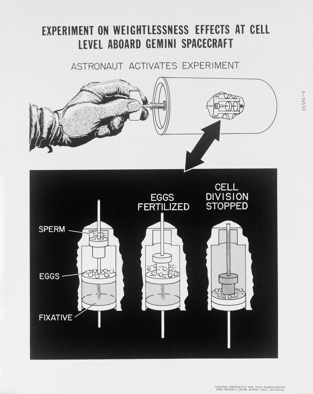
S65-18766 (March 1965) --- Diagram of experiment planned for the Gemini-Titan 3 mission scheduled on March 23, 1965, to find out if there are effects of weightlessness on individual living cells. The round canister (top) shows the experiment package. It will contain eight identical chambers, each with sections of sperm, eggs and fixative. Cells are eggs of the spiny, black sea animal, the sea urchin. Bottom panel shows the three stages of each chamber. From left in the first stage, sperm, eggs and fixative are separated. By turning the handle, astronauts will fertilize a certain portion of the eggs, which will begin to divide. At 20 minutes after launch, further turns of the handle will force fixative into two chambers and stop cell division. At 70 minutes after launch, cell division in four more chambers will be stopped, and just prior to re-entry, growth of the remaining two chambers will be terminated by a turn of the handle. This system will allow study after the flight of how cells divided after various time periods in weightlessness. Abnormalities would suggest weightlessness effects on living tissue and possible hazard to prolonged manned spaceflight.
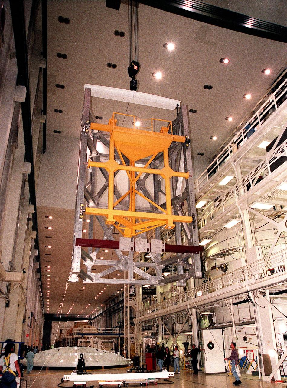
KENNEDY SPACE CENTER, FLA. -- In the Operations and Checkout Building's high bay, a crane lifts the Rotation Handling Fixture (RHF) and simulated module during a test. Under normal operation, the RHF will hold a pressurized module intended for the International Space Station, lifting it up and into an altitude chamber for leak testing. The chamber was recently reactivated after a 24-year hiatus. Originally, two chambers were built to test Apollo Program flight hardware. They were last used in 1975 during the Apollo-Soyuz Test Project. In 1997, in order to increase the probability of successful missions aboard the ISS, NASA decided to perform leak tests on ISS pressurized modules at the launch site. After installation of new vacuum pumping equipment and controls, a new control room, and a new rotation and handling fixture, the chamber again became operational in February 1999. The chamber, which is 33 feet in diameter and 50 feet tall, is constructed of stainless steel. The rotation handling fixture is aluminum. The first module that will be tested for leaks is the U.S. Laboratory. No date has been determined for the test
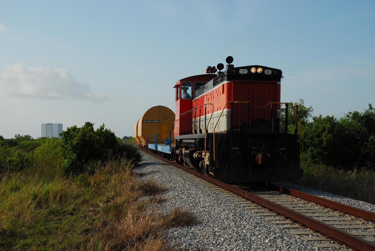
KENNEDY SPACE CENTER, FLA. -- The locomotive and rail cars carrying solid rocket booster motor segments and two aft exit cone segments roll to the Rotation, Processing and Surge Facility (RPSF) in Kennedy Space Center's Launch Complex 39 Area. In the background, at left, is the Vehicle Assembly Building. The RPSF is used for solid rocket motor receiving, rotation and inspection, and supports aft booster buildup. When live solid rocket motor segments arrive at the processing facility, they are positioned under one of the cranes. Handling slings are then attached to and remove the railcar cover. The segment is inspected while it remains horizontal. The two overhead cranes hoist the segment, rotate it to a vertical position and place it on a fixed stand. The aft handling ring is then removed. The segment is hoisted again and lowered onto a transportation and storage pallet, and the forward handling ring is removed to allow inspections. It is then transported to one of the surge buildings and temporarily stored until it is needed for booster stacking in the VAB. While enroute, solid rocket motor segments were involved in a derailment in Alabama. The rail cars carrying these segments remained upright and were undamaged. An inspection determined these segment cars could continue on to Florida. The segments themselves will undergo further evaluation at Kennedy before they are cleared for flight. Other segments involved in the derailment will be returned to a plant in Utah for further evaluation. Photo credit: NASA/George Shelton

This galaxy is known as Mrk 820 and is classified as a lenticular galaxy — type S0 on the Hubble Tuning Fork. The Hubble Tuning Fork is used to classify galaxies according to their morphology. Elliptical galaxies look like smooth blobs in the sky and lie on the handle of the fork. They are arranged along the handle based on how elliptical they are, with the more spherical galaxies furthest from the tines of the fork, and the more egg-shaped ones closest to the end of the handle where it divides. The two prongs of the tuning fork represent types of unbarred and barred spiral galaxies. Lenticular galaxies like Mrk 820 are in the transition zone between ellipticals and spirals and lie right where the fork divides. A closer look at the appearance of Mrk 820 reveals hints of a spiral structure embedded in a circular halo of stars. Surrounding Mrk 820 in this image is good sampling of other galaxy types, covering almost every type found on the Hubble Tuning Fork, both elliptical and spiral. Most of the smears and specks are distant galaxies, but the prominent bright object at the bottom is a foreground star called TYC 4386-787-1. A version of this image was entered into the Hubble's Hidden Treasures image processing competition by contestant Judy Schmidt.
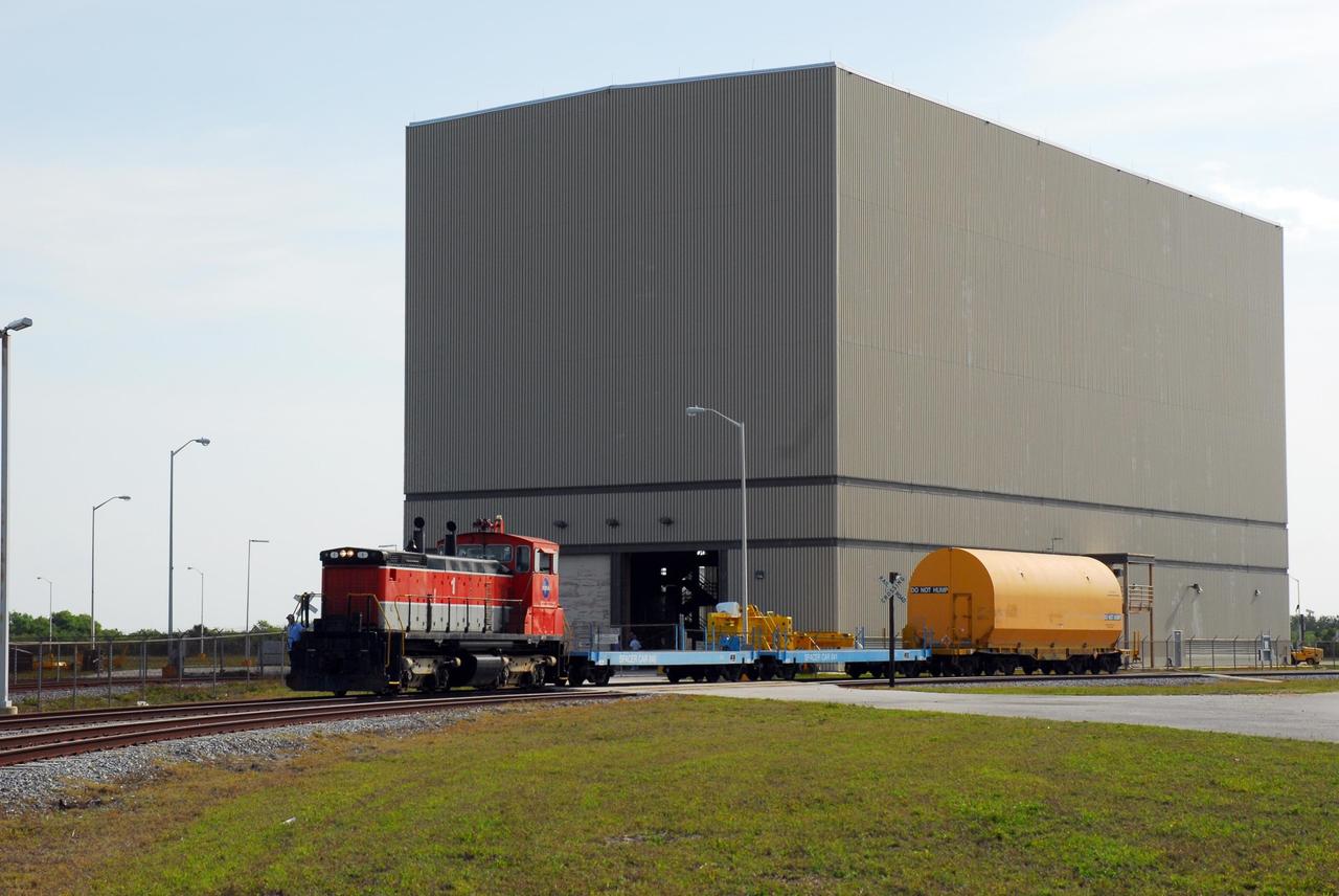
KENNEDY SPACE CENTER, FLA. -- The locomotive and rail cars carrying solid rocket booster motor segments and two aft exit cone segments deliver their cargo to the Rotation, Processing and Surge Facility (RPSF) in Kennedy Space Center's Launch Complex 39 Area. The RPSF is used for solid rocket motor receiving, rotation and inspection, and supports aft booster buildup. When live solid rocket motor segments arrive at the processing facility, they are positioned under one of the cranes. Handling slings are then attached to and remove the railcar cover. The segment is inspected while it remains horizontal. The two overhead cranes hoist the segment, rotate it to a vertical position and place it on a fixed stand. The aft handling ring is then removed. The segment is hoisted again and lowered onto a transportation and storage pallet, and the forward handling ring is removed to allow inspections. It is then transported to one of the surge buildings and temporarily stored until it is needed for booster stacking in the VAB. While enroute, solid rocket motor segments were involved in a derailment in Alabama. The rail cars carrying these segments remained upright and were undamaged. An inspection determined these segment cars could continue on to Florida. The segments themselves will undergo further evaluation at Kennedy before they are cleared for flight. Other segments involved in the derailment will be returned to a plant in Utah for further evaluation. Photo credit: NASA/George Shelton
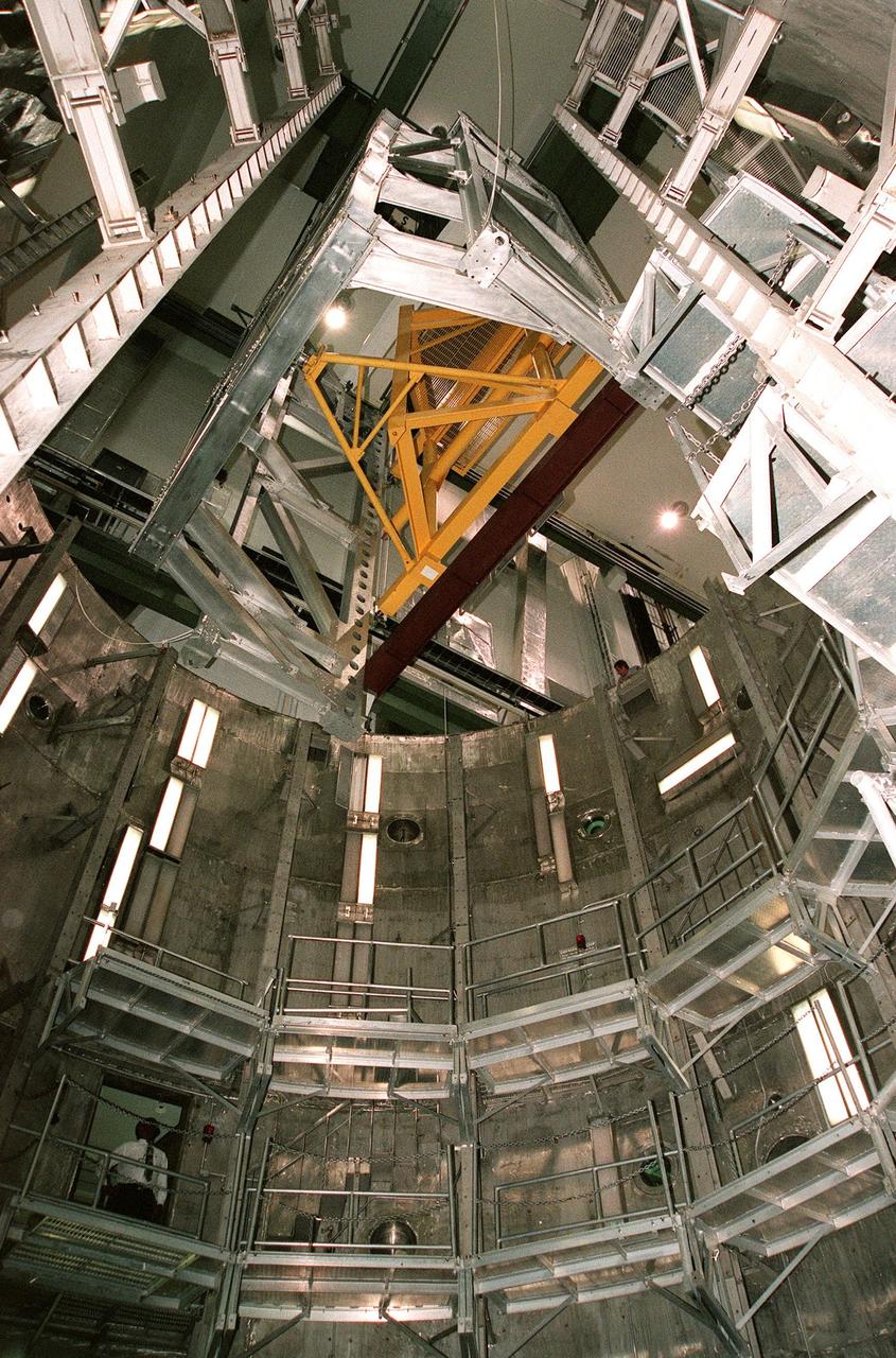
KENNEDY SPACE CENTER, FLA. -- Viewed from inside the altitude chamber in the Operations and Checkout Building's high bay, the Rotation Handling Fixture (RHF), with a simulated module attached, is lowered during a test. Under normal operation, the RHF will hold a pressurized module intended for the International Space Station, depositing it into the altitude chamber for leak testing. The chamber was recently reactivated after a 24-year hiatus. Originally, two chambers were built to test Apollo Program flight hardware. They were last used in 1975 during the Apollo-Soyuz Test Project. In 1997, in order to increase the probability of successful missions aboard the ISS, NASA decided to perform leak tests on ISS pressurized modules at the launch site. After installation of new vacuum pumping equipment and controls, a new control room, and a new rotation and handling fixture, the chamber again became operational in February 1999. The chamber, which is 33 feet in diameter and 50 feet tall, is constructed of stainless steel. The rotation handling fixture is aluminum. The first module that will be tested for leaks is the U.S. Laboratory. No date has been determined for the test
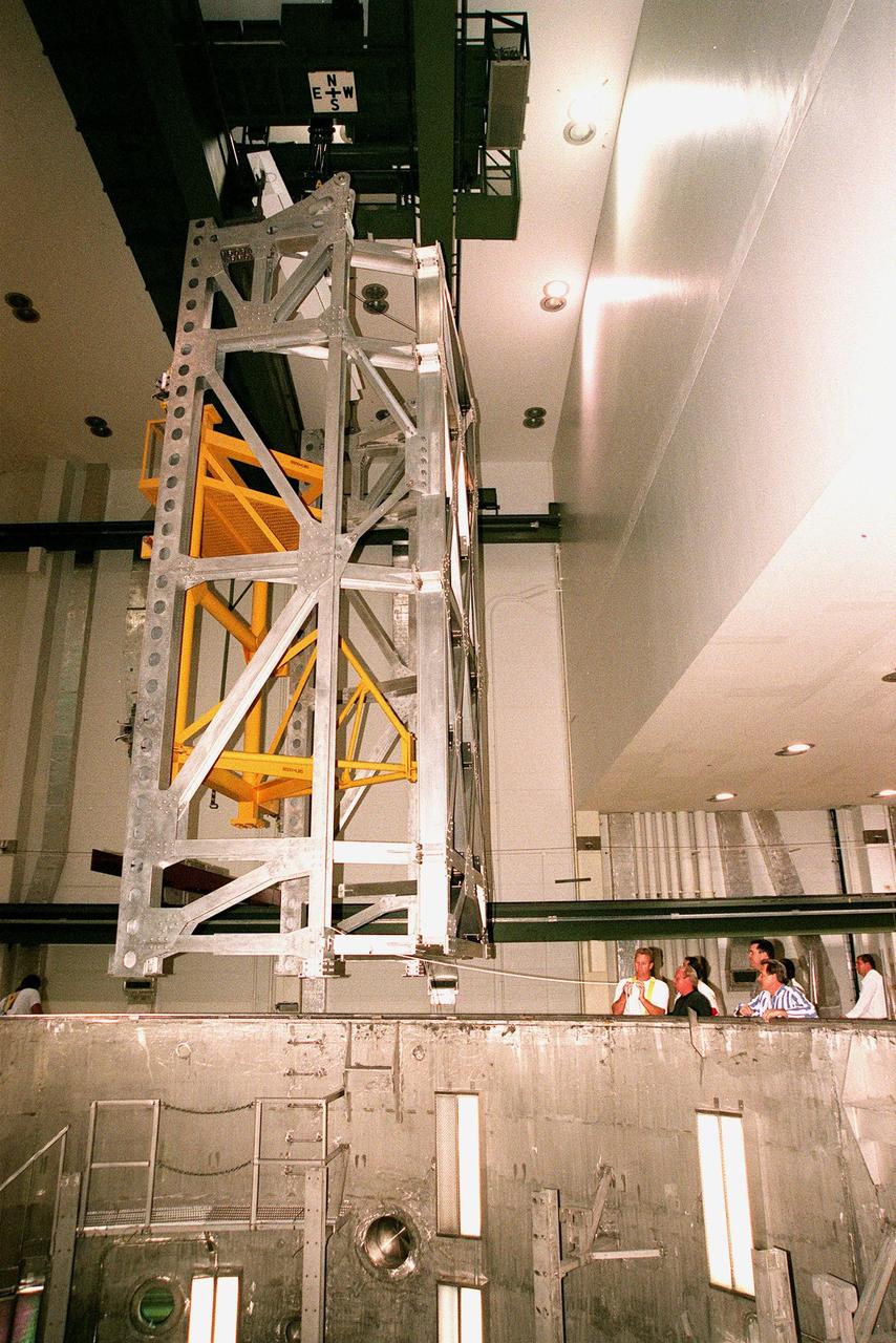
KENNEDY SPACE CENTER, FLA. -- In the Operations and Checkout Building's high bay, the Rotation Handling Fixture (RHF), with a simulated module attached, is lowered by crane into the altitude chamber below during a test. Under normal operation, the RHF will hold a pressurized module intended for the International Space Station, depositing it into the altitude chamber for leak testing. The chamber was recently reactivated after a 24-year hiatus. Originally, two chambers were built to test Apollo Program flight hardware. They were last used in 1975 during the Apollo-Soyuz Test Project. In 1997, in order to increase the probability of successful missions aboard the ISS, NASA decided to perform leak tests on ISS pressurized modules at the launch site. After installation of new vacuum pumping equipment and controls, a new control room, and a new rotation and handling fixture, the chamber again became operational in February 1999. The chamber, which is 33 feet in diameter and 50 feet tall, is constructed of stainless steel. The rotation handling fixture is aluminum. The first module that will be tested for leaks is the U.S. Laboratory. No date has been determined for the test
CAPE CANAVERAL, Fla. – In Orbiter Processing Facility OPF Bay 2 at NASA’s Kennedy Space Center in Florida, weight and center of gravity checks are underway on the space shuttle Endeavour. Monitoring data on the activity are United Space Alliance USA OPF Manager Mark Barnes, standing to the left, and Mike McClure, of USA Orbiter Handling Engineering. Seated, from the left, are USA move director Cliff Semonski, USA move director Mark McGee, USA lead aerospace Quality Mission Assurance inspector Jesse English, Doug Robison, of USA Orbiter Handling Engineering, and Robert Handl, of Boeing Mass Properties. The work is part of Transition and Retirement of the remaining space shuttles, Endeavour and Atlantis. Endeavour is being prepared for public display at the California Science Center in Los Angeles. Its ferry flight to California is targeted for mid-September. Endeavour was the last space shuttle added to NASA’s orbiter fleet. Over the course of its 19-year career, Endeavour spent 299 days in space during 25 missions. For more information, visit http://www.nasa.gov/transition Photo credit: NASA/ Jim Grossmann
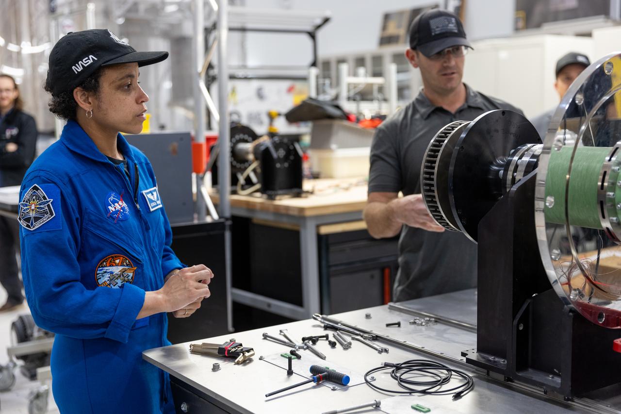
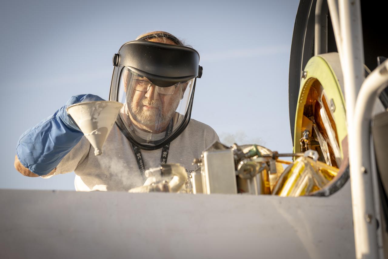
NASA astronaut Jessica Watkins visits the Granular Mechanics and Regolith Operations Laboratory inside Swamp Works at Kennedy Space Center in Florida on Wednesday, Aug. 27, 2025, to view some of the evolving technologies in development that astronauts may use to explore the Moon’s surface, prepare it for sustainable outposts, and to handle the dust that is collected during moonwalks.
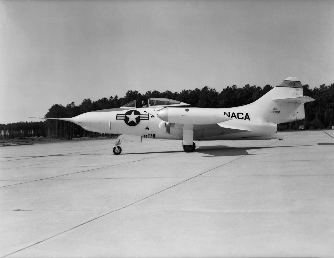
Grumman F9F-2 Panther: Originally built as a F9F-3, this Grumman F9F-2 Panther has a Pratt and Whitney J42 turbojet power plant, hence the designation change. This Panther underwent handling quality tests, serving long enough at Langley to witness the change from the NACA to NASA.
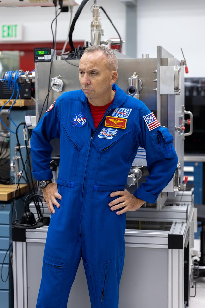
NASA astronaut Randy Bresnik visits the Granular Mechanics and Regolith Operations Laboratory inside Swamp Works at Kennedy Space Center in Florida on Wednesday, Aug. 27, 2025, to view some of the evolving technologies in development that astronauts may use to explore the Moon’s surface, prepare it for sustainable outposts, and to handle the dust that is collected during moonwalks.

S96-E-5234 (3 June 1999) --- A STS-96 crew member handling an electronic still camera (ESC) recorded this image of the International Space Station (ISS) during a flyaround following separation of the two spacecraft. The image was recorded at 23:12:29 GMT, June 3, 1999.
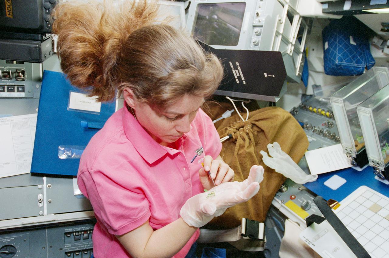
STS093-319-003 (23-27 July 1999) --- Astronaut Catherine G. (Cady) Coleman, mission specialist, handles a tiny mouse ear plant on Columbia's flight deck. The plant experiment is part of the Plant Growth Investigations in Microgravity (PGIM).

Astronaut Dale A. Gardner, 51-A mission specialist, rehearses control of manned maneuvering unit (MMU) during a practice for an extravehicular activity (EVA). Gardner is in the Shuttle mockup and integration laboratory at JSC. Gardner handles a stinger device to make initial contact with one of the two satellites they will be working with.

ISS006-E-40545 (March 2003) --- The bowl and a portion of the “handle” stars of the Big Dipper are visible in this photograph taken by astronaut Donald R. Pettit, Expedition Six NASA ISS science officer, on board the International Space Station (ISS).

STS79-E-5366 (16-26 September 1996) --- Astronaut Carl E. Walz handles the IMAX in-cabin motion picture camera, which was used to capture some of the same imagery seen in this series of Electronic Still Camera (ESC) views.
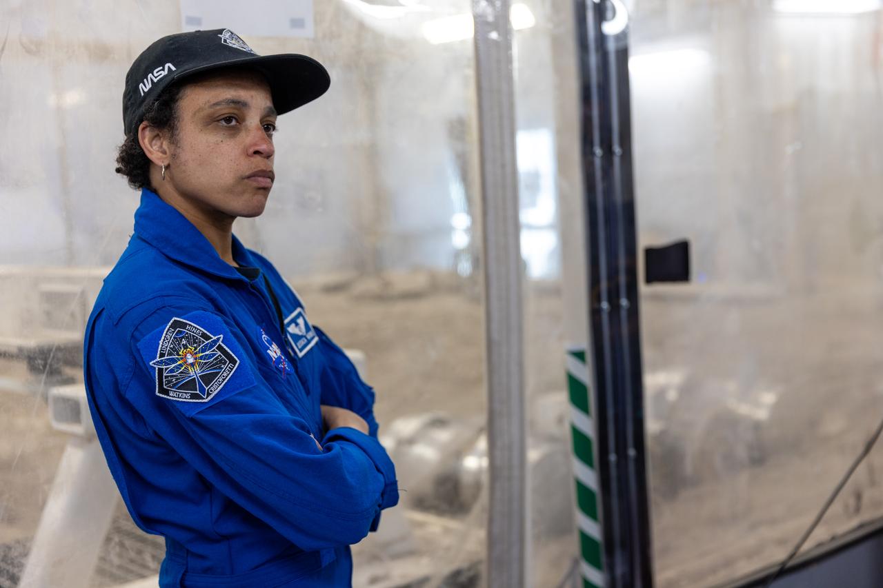
NASA astronaut Jessica Watkins visits the Granular Mechanics and Regolith Operations Laboratory inside Swamp Works at Kennedy Space Center in Florida on Wednesday, Aug. 27, 2025, to view some of the evolving technologies in development that astronauts may use to explore the Moon’s surface, prepare it for sustainable outposts, and to handle the dust that is collected during moonwalks.
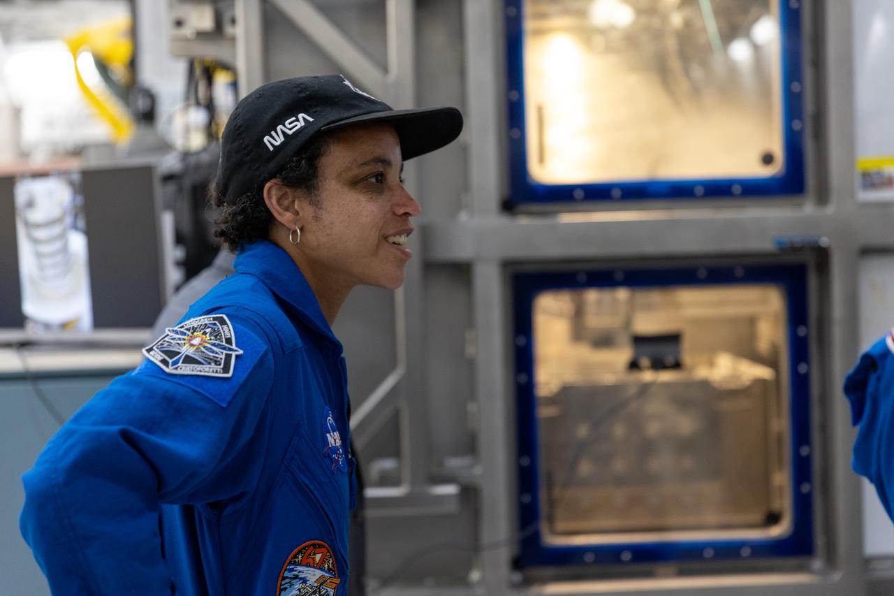
NASA astronaut Jessica Watkins visits the Granular Mechanics and Regolith Operations Laboratory inside Swamp Works at Kennedy Space Center in Florida on Wednesday, Aug. 27, 2025, to view some of the evolving technologies in development that astronauts may use to explore the Moon’s surface, prepare it for sustainable outposts, and to handle the dust that is collected during moonwalks.
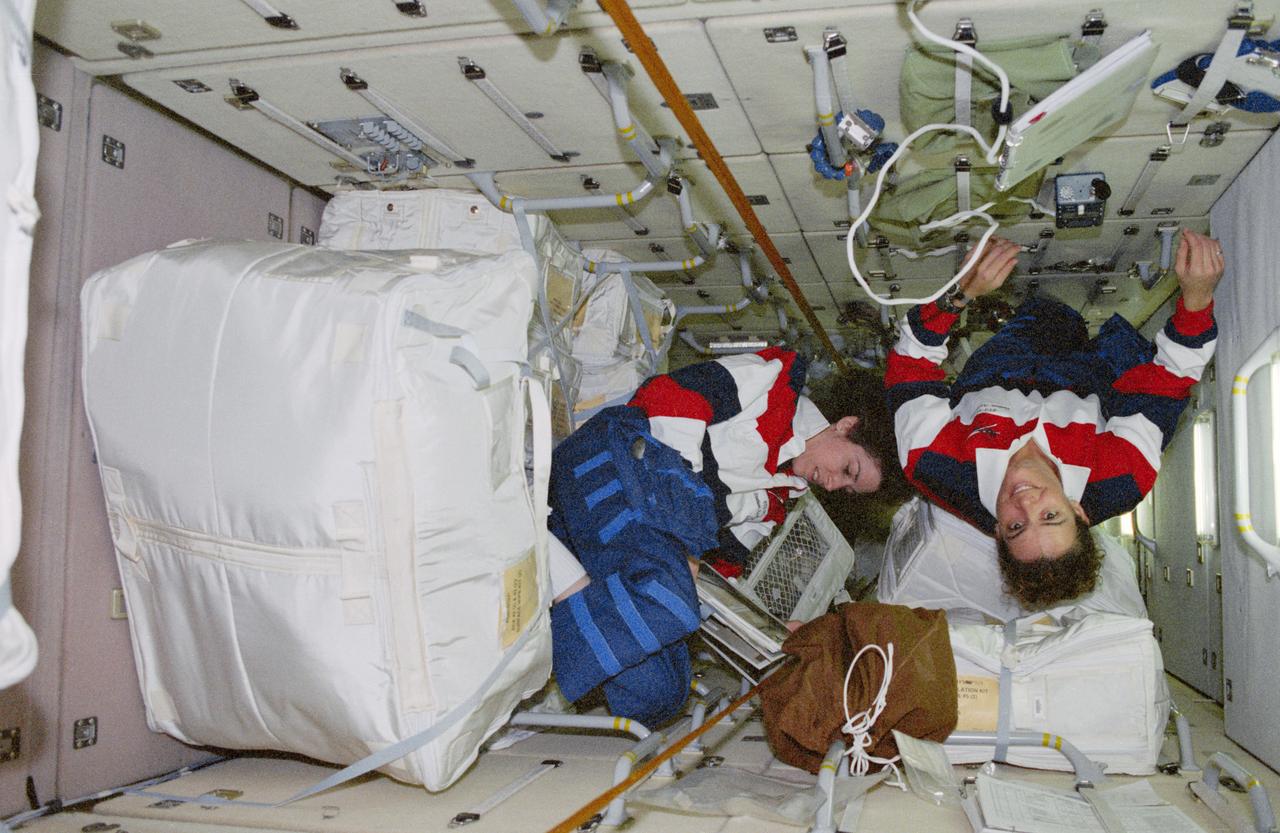
STS096-364-015 (27 May - 6 June 1999) --- Onboard the Russian-built Zarya module, astronauts Julie Payette (left) and Ellen Ochoa handle a portion of the supplies which have been moved over from the docked Discovery. Payette represents the Canadian Space Agency (CSA).
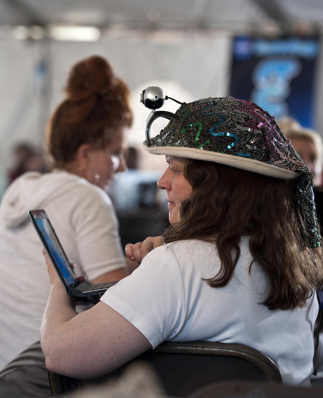
Heather Good, Twitter handle @foundonmars, tweets during the STS-134 Tweetup, Thursday, April 28, 2011, at Kennedy Space Center in Cape Canaveral, Fla. About 150 NASA Twitter followers attended the event. Photo Credit: (NASA/Paul E. Alers)
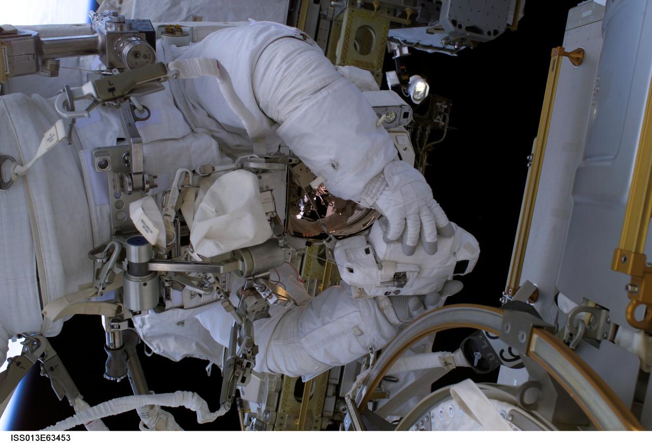
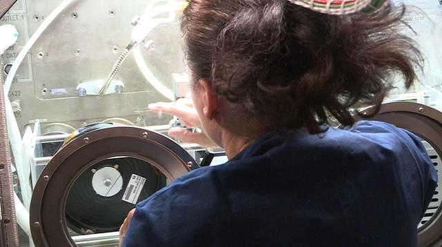
ISS013-E-63453 (3 August 2006) --- Astronaut Thomas Reiter, who represents the European Space Agency on the Expedition 13 crew, handles the infrared camera used to photograph a set of reinforced carbon carbon (RCC) samples for possible detection of damage caused by variations in temperature between sound and damaged RCC test sections.
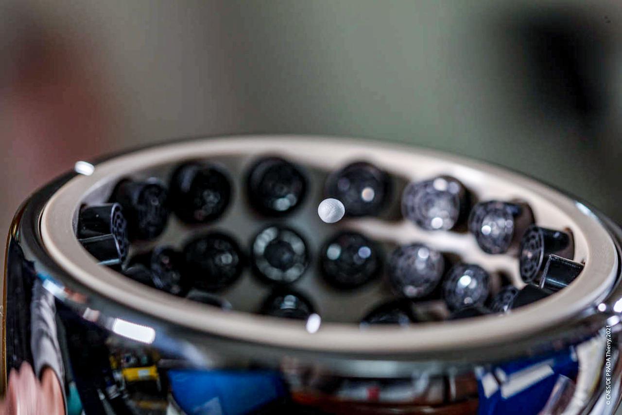
jsc2021e020420 (2/10/2021) --- A preflight view of the Ultrasonic Tweezers handle trapping a polystyrene sphere during hardware verification. The objective of the Ultrasonic Tweezers project is to develop acoustic tweezers that use sound to allow for remote and contactless manipulation of materials in a microgravity context. Image courtesy of CNES/T. De Prada.
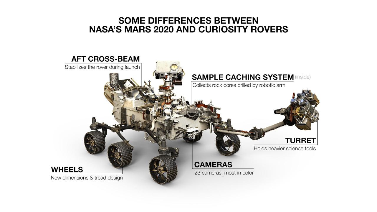
NASA's Mars 2020 rover looks virtually the same as Curiosity, but there are a number of differences. One giveaway to which rover you're looking at is 2020's aft cross-beam, which looks a bit like a shopping cart handle. https://photojournal.jpl.nasa.gov/catalog/PIA23516
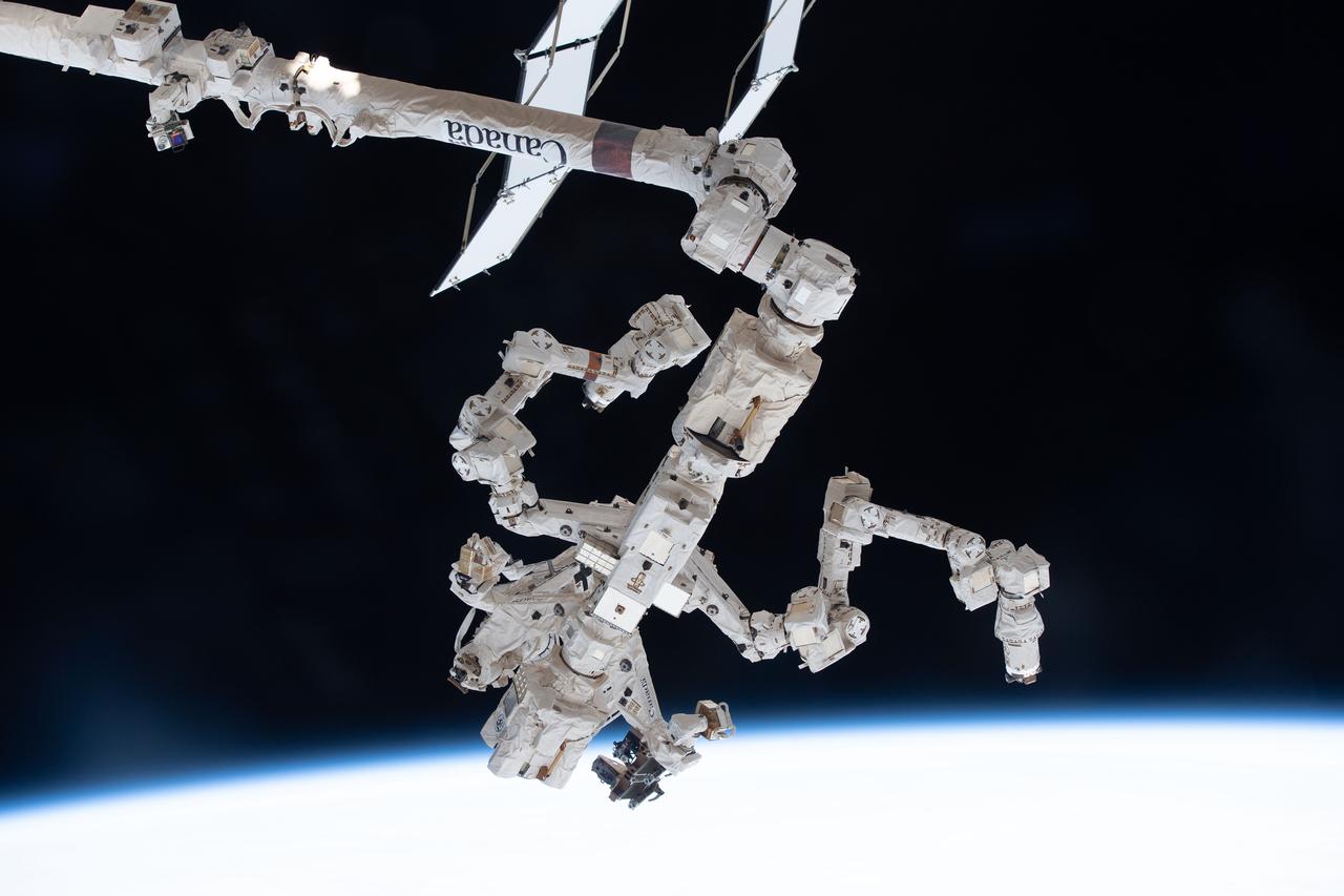
iss067e356122 (Sept. 10, 2022) --- The Special Purpose Dexterous Manipulator (SPDM), also known as Dextre, is pictured attached to the International Space Station's Canadarm2 robotic arm. The SPDM is the orbiting lab's fine-tuned robotic hand designed for precise handling abilities and routine maintenance tasks such as replacing batteries and cameras in the harsh environment of space.
STS100-385-009 (19 April-1 May 2001) --- Extended by a crewmember on the International Space Station (ISS), the Space Station Remote Manipulator System (SSRMS) is backdropped by the blackness of space and the Earth's horizon while handling the Spacelab pallet.
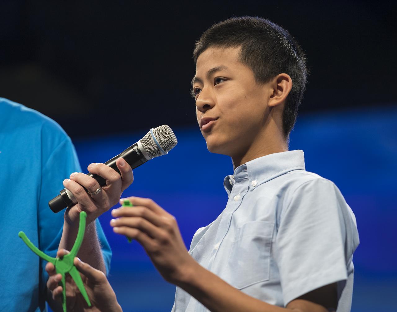
Future Engineers "Two for the Crew" competition winner, Jason Qin, speaks about his Two Pliers + 1 Handle, during a STEM in 30 event, Wednesday, June 27, 2018 at Smithsonian's National Air and Space Museum in Washington. Photo Credit: (NASA/Aubrey Gemignani)
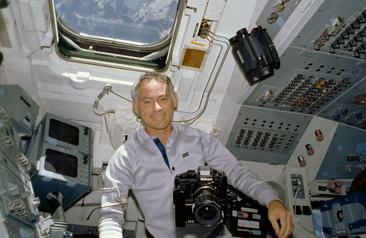
STS027-10-021 (2-6 Dec. 1988) --- Astronaut Richard M. (Mike) Mullane, STS-27 mission specialist, is able to handle a number of cameras with the aid of the microgravity in the shirt sleeve environment of the Earth-orbiting space shuttle Atlantis. Photo credit: NASA
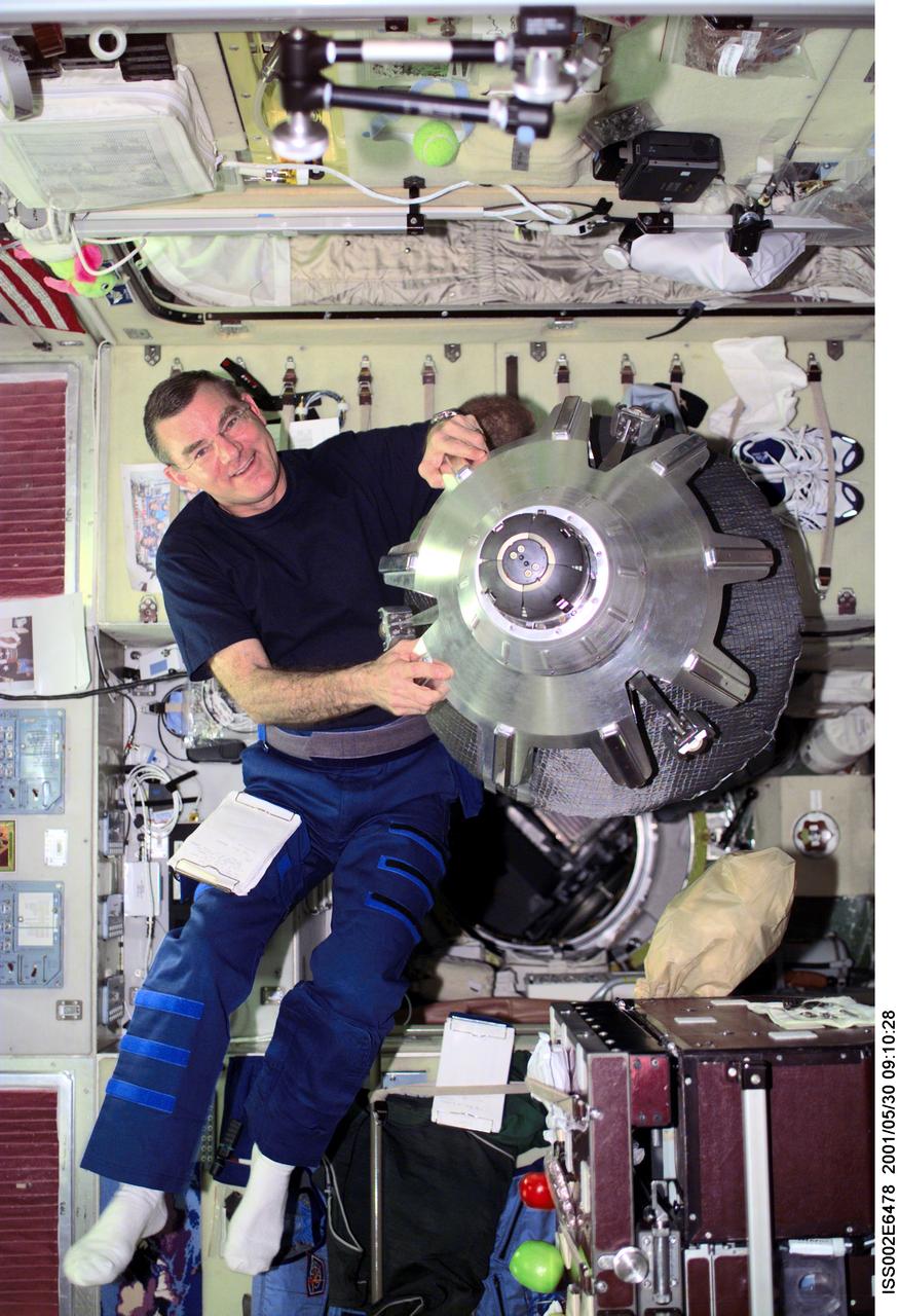
ISS002-E-6478 (30 May 2001) --- James S. Voss, Expedition Two flight engineer, handles a spacecraft docking probe in the Service Module. The docking probe assists with the docking of the Soyuz and Progress vehicles to the International Space Station. The image was taken with a digital still camera.
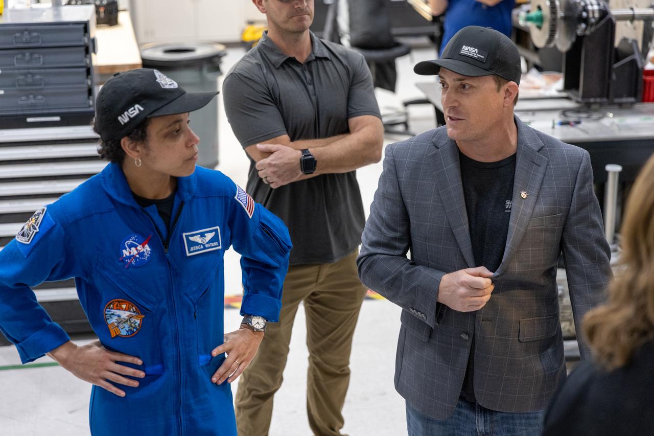
NASA astronaut Jessica Watkins visits the Granular Mechanics and Regolith Operations Laboratory inside Swamp Works at Kennedy Space Center in Florida on Wednesday, Aug. 27, 2025, to view some of the evolving technologies in development that astronauts may use to explore the Moon’s surface, prepare it for sustainable outposts, and to handle the dust that is collected during moonwalks.

ISS003-E-8045 (23-31 October 2001) --- Cosmonaut Mikhail Tyurin (left), Expedition Three flight engineer, and Soyuz Taxi crewmember, Flight Engineer Konstantin Kozeev, work in the Zvezda Service Module’s transfer compartment on the International Space Station (ISS). Tyurin and Kozeev represent Rosaviakosmos.
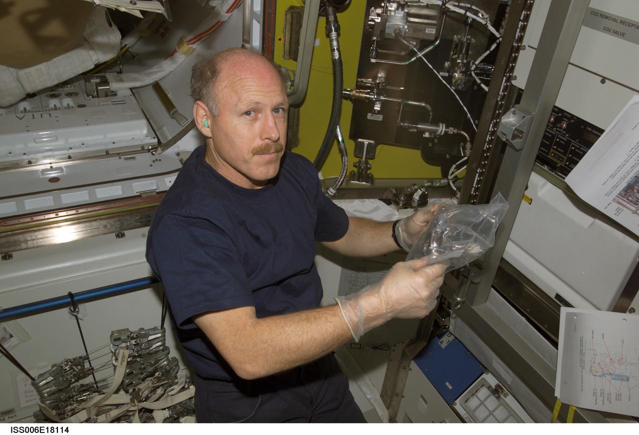
ISS006-E-18114 (18 January 2003) --- Astronaut Kenneth D. Bowersox, Expedition Six mission commander, is pictured in the Quest Airlock on the International Space Station (ISS).

ISS003-E-6547 (10 October 2001) --- Cosmonaut Mikhail Tyurin, Expedition Three flight engineer representing Rosaviakosmos, works with Japan’s National Space Development Agency (NASDA) hardware for the Micro-Particles Capturer (MPAC) and Space Environment Exposure Device (SEED) experiment in the Zvezda Service Module on the International Space Station (ISS). This image was taken with a digital still camera.
S93-E-5006 (23 July 1999) --- Astronaut Michel Tognini, mission specialist representing the French space agency (CNES), opens the gaseous nitorgen (GN2) freezer on Columbia's middeck. The freezer is flown in support of two plant growth experiments--Plant Growth Investigations in Microgravity (PGIM) and Biological Research in Canisters (BRIC). Throughout the mission Tognini periodically freezes samples from the experiments to provide glimpses of the plants in various stages of development. The photo was recorded with an electronic still camera (ESC) on Flight Day 1.
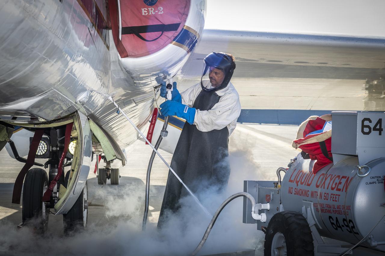
Francisco Rodriguez (aircraft mechanic) services liquid oxygen or LOX on the ER-2 during the Geological Earth Mapping Experiment (GEMx) research project. Experts like Rodriguez sustain a high standard of safety on airborne science aircraft like the ER-2 and science missions like GEMx. The ER-2 is based out of NASA’s Armstrong Flight Research Center in Edwards, California.
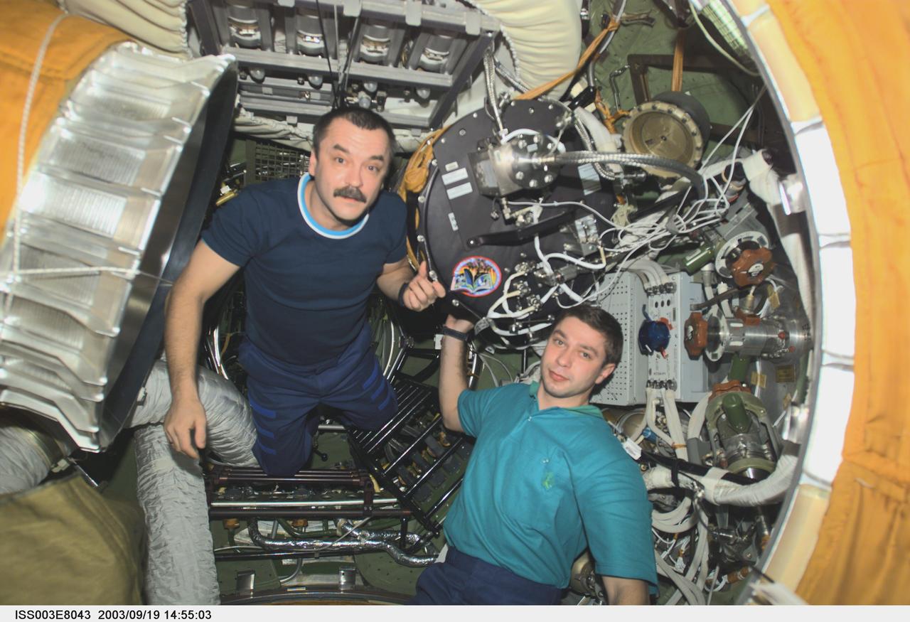
ISS003-E-8043 (23-31 October 2001) --- Cosmonaut Mikhail Tyurin (left), Expedition Three flight engineer, and Soyuz Taxi crewmember, Flight Engineer Konstantin Kozeev, work in the Zvezda Service Module’s transfer compartment on the International Space Station (ISS). Tyurin and Kozeev represent Rosaviakosmos.