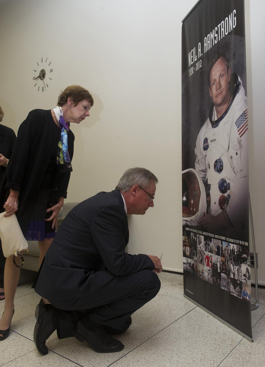
JAMES HANSEN AND HIS WIFE MARGARET INSPECT PHOTOS ON DISPLAY OF NEIL ARMSTRONG PRIOR TO HANSEN’S PRESENTATION TO MSFC EMPLOYEES ABOUT THE LIFE OF ARMSTRONG IN MORRIS AUDITORIUM

Author James Hansen, left, arrives on the red carpet for the premiere of the film "First Man" at the Smithsonian National Air and Space Museum Thursday, Oct. 4, 2018 in Washington. The film is based on the book by Jim Hansen, and chronicles the life of NASA astronaut Neil Armstrong from test pilot to his historic Moon landing. Photo Credit: (NASA/Aubrey Gemignani)
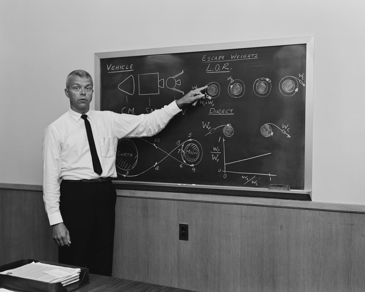
At blackboard, showing his space rendezvous concept for lunar landings. Lunar Orbital Rendezvous (LOR) would be used in the Apollo program. Photograph published in Space Flight Revolution - NASA Langley Research Center From Sputnik to Apollo (page 247), by James R. Hansen.
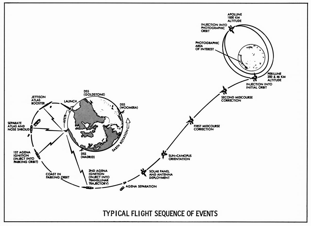
Lunar Orbiter's "Typical Flight sequence of Events" turned out to be quite typical indeed, as all five spacecraft performed exactly as planned. -- Published in James R. Hansen, Spaceflight Revolution: NASA Langley Research Center From Sputnik to Apollo, (Washington: NASA, 1995), p. 340.
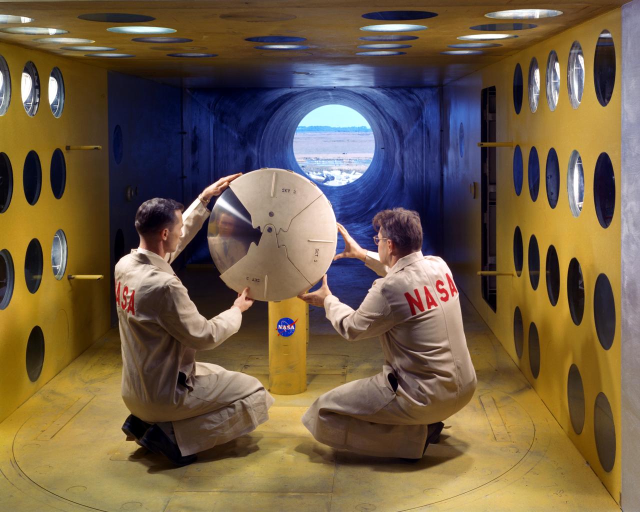
As part of the project FIRE study, technicians ready materials to be subjected to high temperatures that will simulate the effects of re-entry heating. Tests of various space capsule materials for Project FIRE were conducted. Photographed in the 9 X 6 Foot Thermal Structures Tunnel. Photograph published in Winds of Change, 75th Anniversary NASA publication, by James Schultz (page 78). Photograph also published in Engineer in Charge: A History of the Langley Aeronautical Laboratory, 1917-1958 by James R. Hansen (page 476). Also Published in the book " A Century at Langley" by Joseph Chambers. Pg. 92
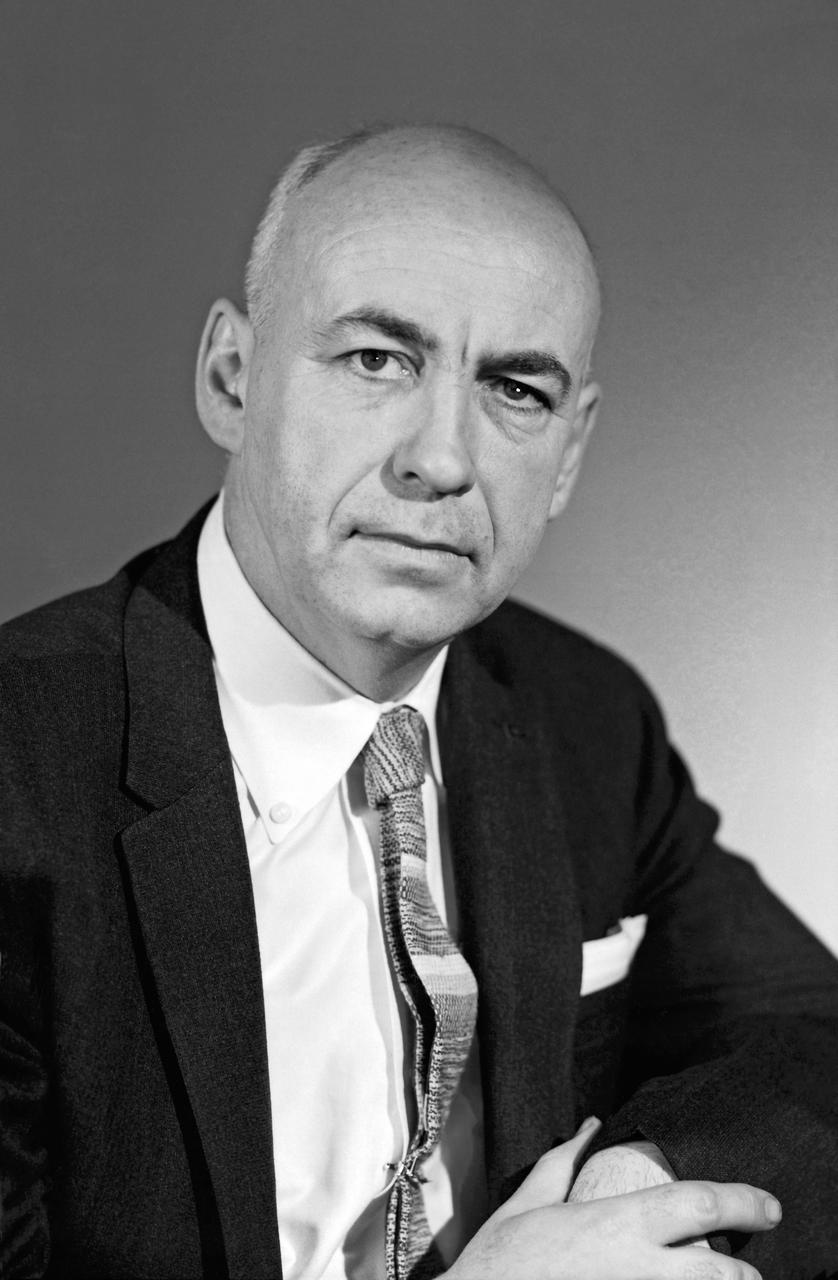
Portrait of Robert R. Gilruth. More than anyone else at Langley, began to push the idea that manned spaceflight was the next great challenge for aeronautic engineers. As head of NASA s Space Task Group, he was responsible for planning and carrying out Project Mercury, the country's first manned spaceflight program. Photograph published in Engineer in Charge: A History of the Langley Aeronautical Laboratory, 1917-1958 by James R. Hansen. Page 386.
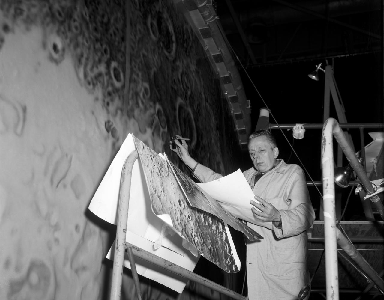
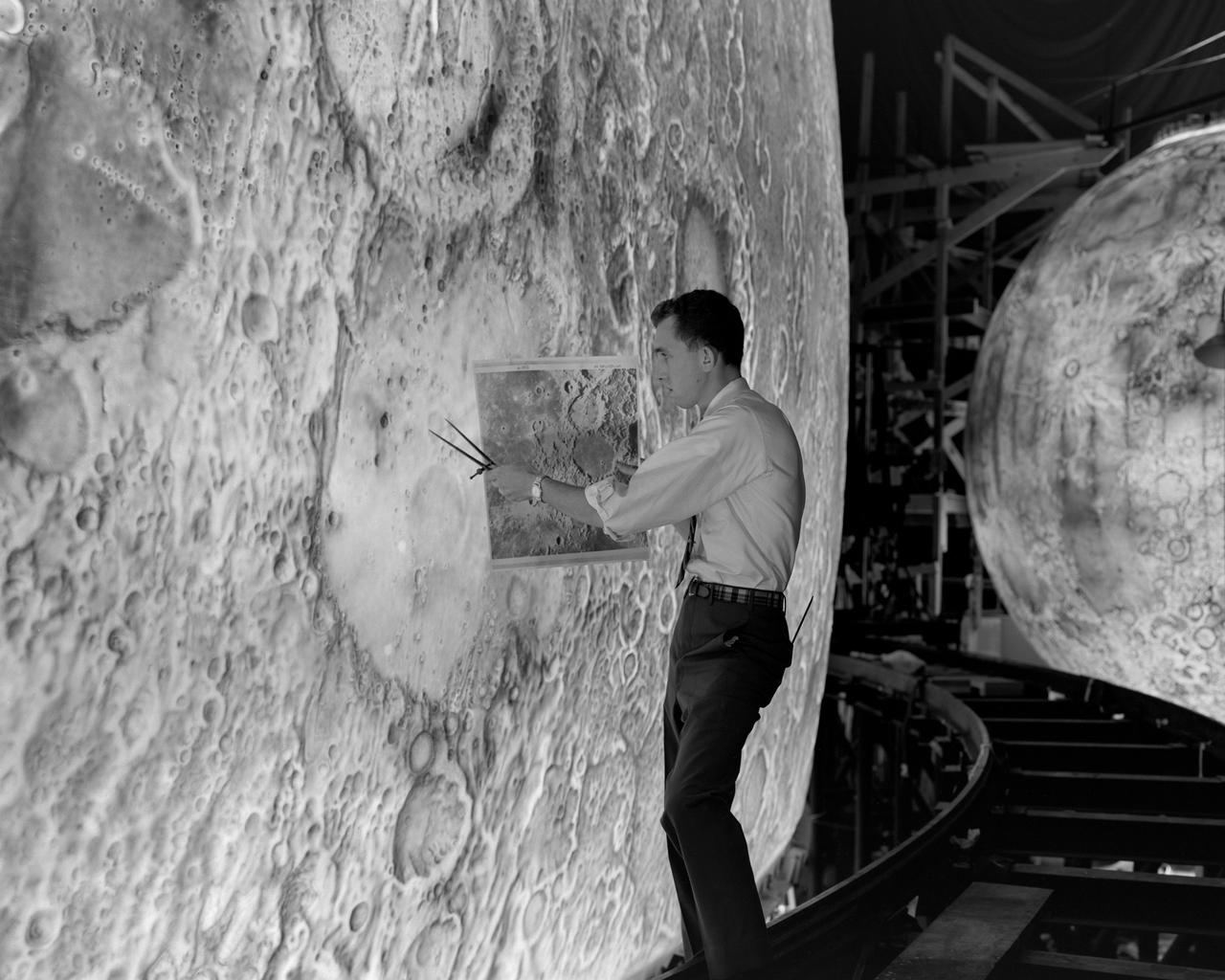
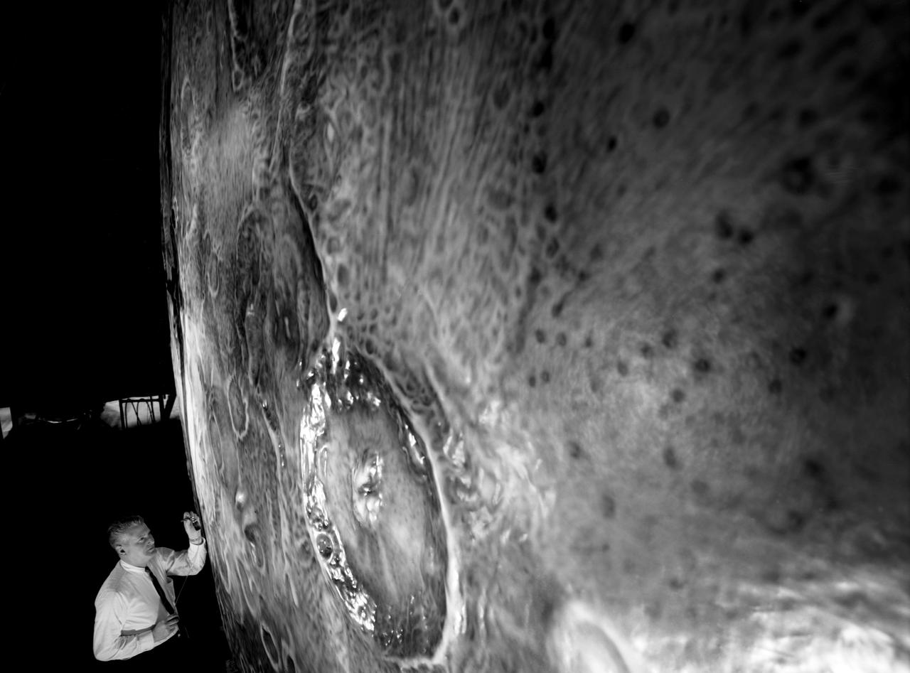
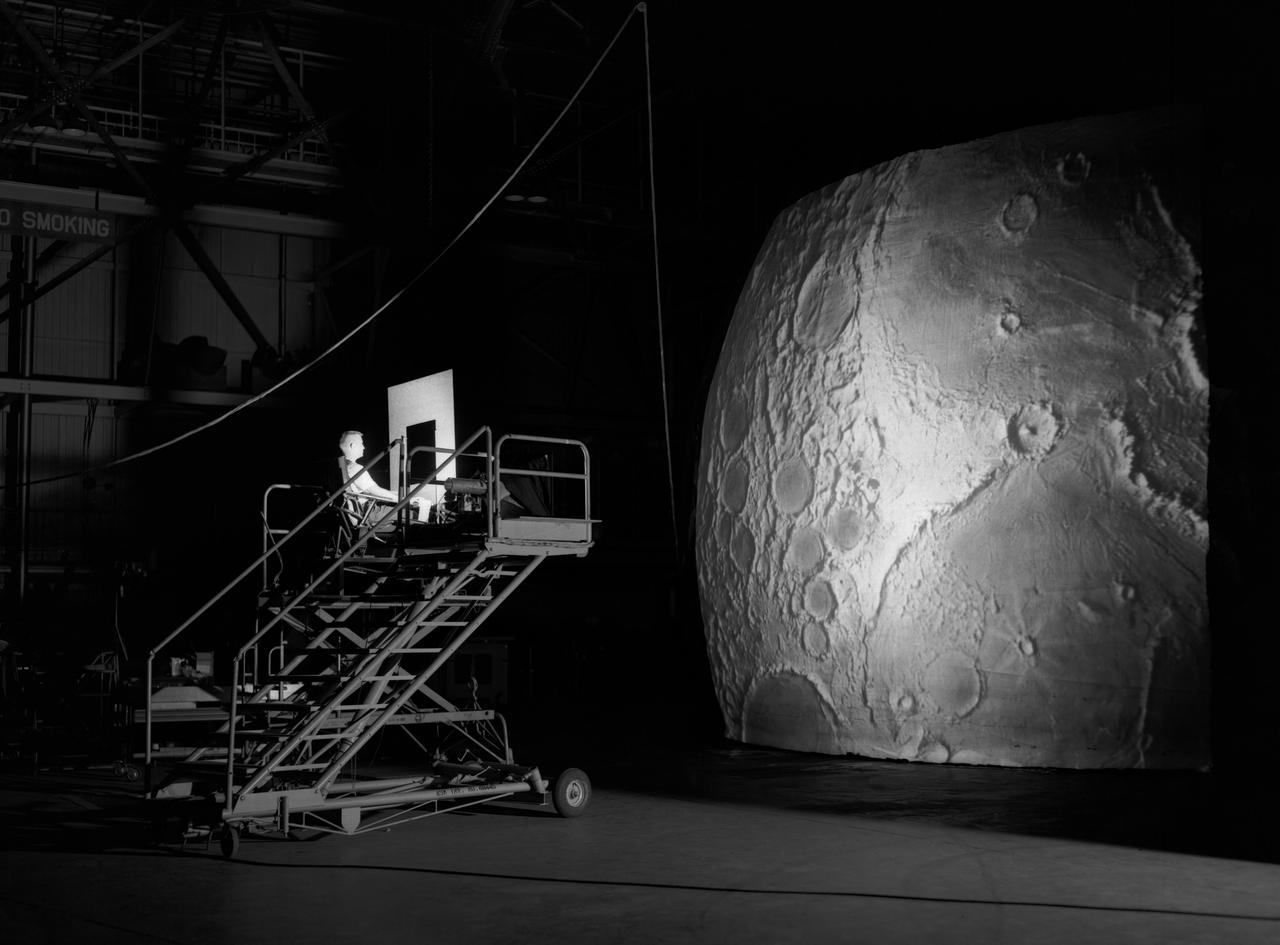
Artists used paintbrushes and airbrushes to recreate the lunar surface on each of the four models comprising the LOLA simulator. Project LOLA or Lunar Orbit and Landing Approach was a simulator built at Langley to study problems related to landing on the lunar surface. It was a complex project that cost nearly $2 million dollars. James Hansen wrote: "This simulator was designed to provide a pilot with a detailed visual encounter with the lunar surface; the machine consisted primarily of a cockpit, a closed-circuit TV system, and four large murals or scale models representing portions of the lunar surface as seen from various altitudes. The pilot in the cockpit moved along a track past these murals which would accustom him to the visual cues for controlling a spacecraft in the vicinity of the moon. Unfortunately, such a simulation--although great fun and quite aesthetic--was not helpful because flight in lunar orbit posed no special problems other than the rendezvous with the LEM, which the device did not simulate. Not long after the end of Apollo, the expensive machine was dismantled." (p. 379) Ellis J. White further described LOLA in his paper "Discussion of Three Typical Langley Research Center Simulation Programs," "Model 1 is a 20-foot-diameter sphere mounted on a rotating base and is scaled 1 in. = 9 miles. Models 2,3, and 4 are approximately 15x40 feet scaled sections of model 1. Model 4 is a scaled-up section of the Crater Alphonsus and the scale is 1 in. = 200 feet. All models are in full relief except the sphere." -- Published in James R. Hansen, Spaceflight Revolution, NASA SP-4308, p. 379; Ellis J. White, "Discussion of Three Typical Langley Research Center Simulation Programs," Paper presented at the Eastern Simulation Council (EAI's Princeton Computation Center), Princeton, NJ, October 20, 1966.
The Mercury space capsule undergoing tests in Full Scale Wind Tunnel, January 1959. Photograph published in Winds of Change, 75th Anniversary NASA publication, page 75, by James Schultz. Also Photograph published in Engineer in Charge: A History of the Langley Aeronautical Laboratory, 1917-1958, page 389, by James R. Hansen.
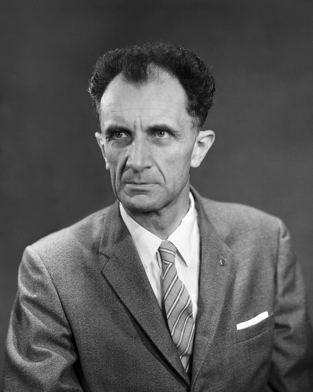
L60-5232 Clinton E. Brown of the Brown Hypersonic Study Group. Photograph published in Engineer in Charge: A History of the Langley Aeronautical Laboratory, 1917-1958 by James R. Hansen. Page 352.
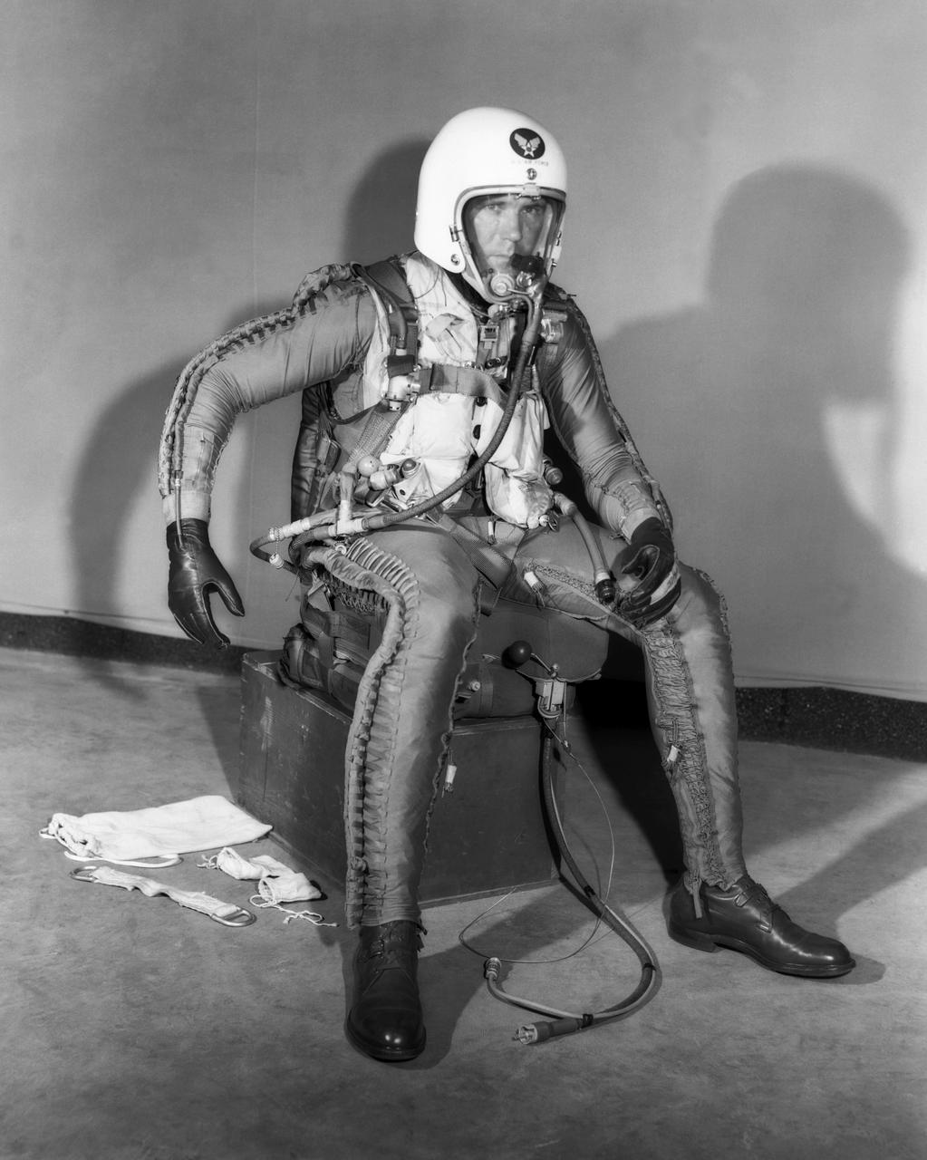
Robert Champine in X-Series Pressure Suit. Photograph published in Engineer in Charge: A History of the Langley Aeronautical Laboratory, 1917-1958 by James R. Hansen. Page 305.
Lunar Landing Research Model. -- Published in James R. Hansen, Spaceflight Revolution: NASA Langley Research Center From Sputnik to Apollo, (Washington: NASA, 1995), p. 356.
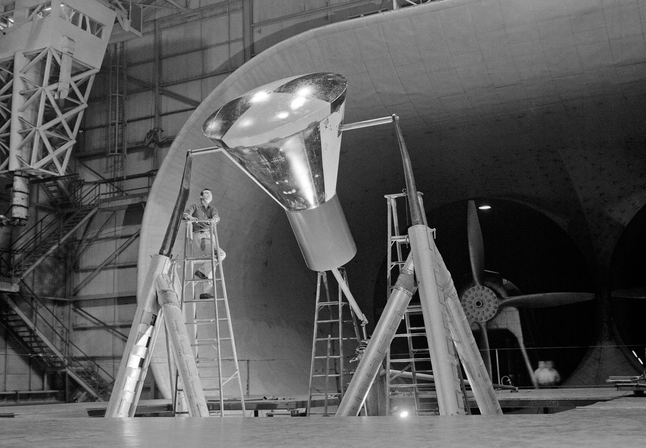
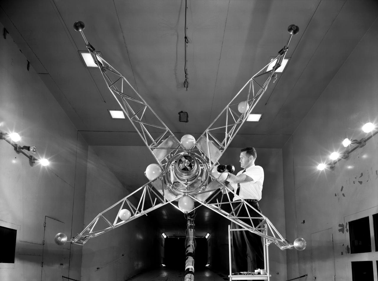
Engineer and 12 foot Beacon showing NACA emblem on inflated satelloon . For related information see, Spaceflight Revolution, NASA from Sputnik to Apollo, by James R. Hansen. NASA SP-4308, 1995. p. 173.
Attitude control simulator for X-15 studies at Langley, 1958. Photograph published in Engineer in Charge: A History of the Langley Aeronautical Laboratory, 1917-1958 by James R. Hansen (page 367).
Engineer and 12 foot Beacon showing NACA emblem on inflated satelloon . For related information see, Spaceflight Revolution, NASA from Sputnik to Apollo, by James R. Hansen. NASA SP-4308, 1995. p. 173.
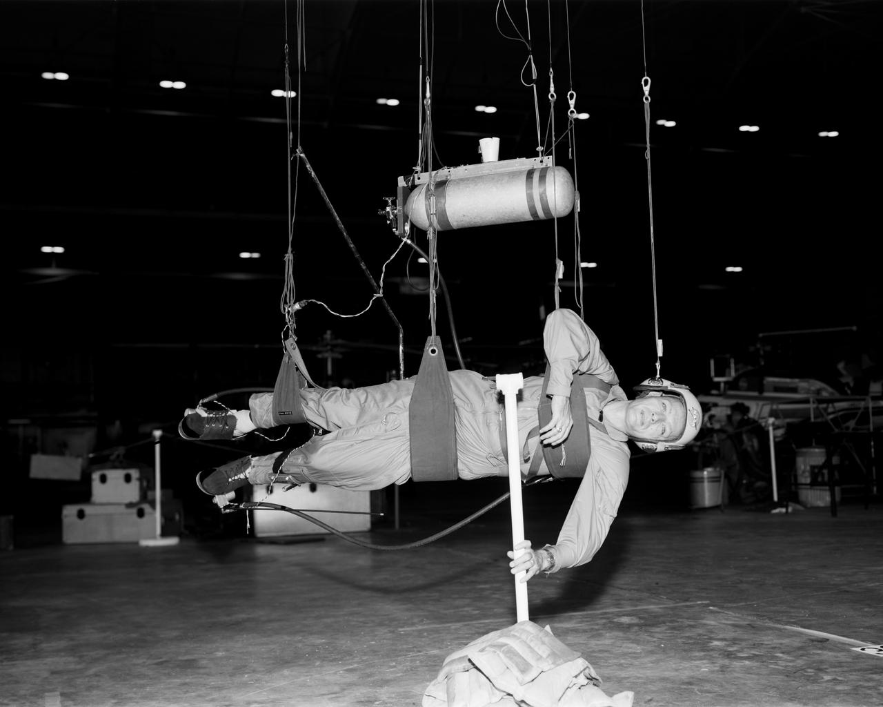
Cable system which supports the test subject on the Reduced Gravity Walking Simulator. The purpose of this simulator was to study the subject while walking, jumping or running. Researchers conducted studies of various factors such as fatigue limit, energy expenditure, and speed of locomotion. A.W. Vigil described the purpose of the simulator as follows: "When the astronauts land on the moon they will be in an unfamiliar environment involving, particularly, a gravitational field only one-sixth as strong as on earth. A novel method of simulating lunar gravity has been developed and is supported by a puppet-type suspension system at the end of a long pendulum. A floor is provided at the proper angle so that one-sixth of the subject's weight is supported by the floor with the remainder being supported by the suspension system. This simulator allows almost complete freedom in vertical translation and pitch and is considered to be a very realistic simulation of the lunar walking problem. For this problem this simulator suffers only slightly from the restrictions in lateral movement it puts on the test subject. This is not considered a strong disadvantage for ordinary walking problems since most of the motions do, in fact, occur in the vertical plane. However, this simulation technique would be severely restrictive if applied to the study of the extra-vehicular locomotion problem, for example, because in this situation complete six degrees of freedom are rather necessary. This technique, in effect, automatically introduces a two-axis attitude stabilization system into the problem. The technique could, however, be used in preliminary studies of extra-vehicular locomotion where, for example, it might be assumed that one axis of the attitude control system on the astronaut maneuvering unit may have failed." -- Published in James R. Hansen, Spaceflight Revolution: NASA Langley Research Center From Sputnik to Apollo, (Washington: NASA, 1995); A.W. Vigil, "Discussion of Existing and Planned Simulators for Space Research," Paper presented at Conference on the Role of Simulation in Space Technology," Blacksburg, VA, August 17-21, 1964.
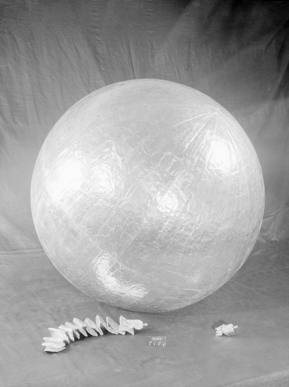
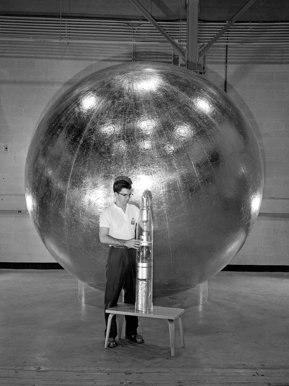
James Hansen describes the work on Project Echo s air density experiment known as the Sub-Satellite. Before launch engineers subjected the sub-satellite to many tests. Here, the sub-satellite is shown prior to tests to determine the capacity of the 30-inch Sub-Satellite to withstand the high temperature of direct sunlight in space, Langley researchers subjected it to 450 F heat test. Results indicated that the aluminum-covered Mylar plastic would effectively reflect the dangerous heat. -- Published in James R. Hansen, Spaceflight Revolution: NASA Langley Research Center From Sputnik to Apollo, NASA SP-4308, p. 168.
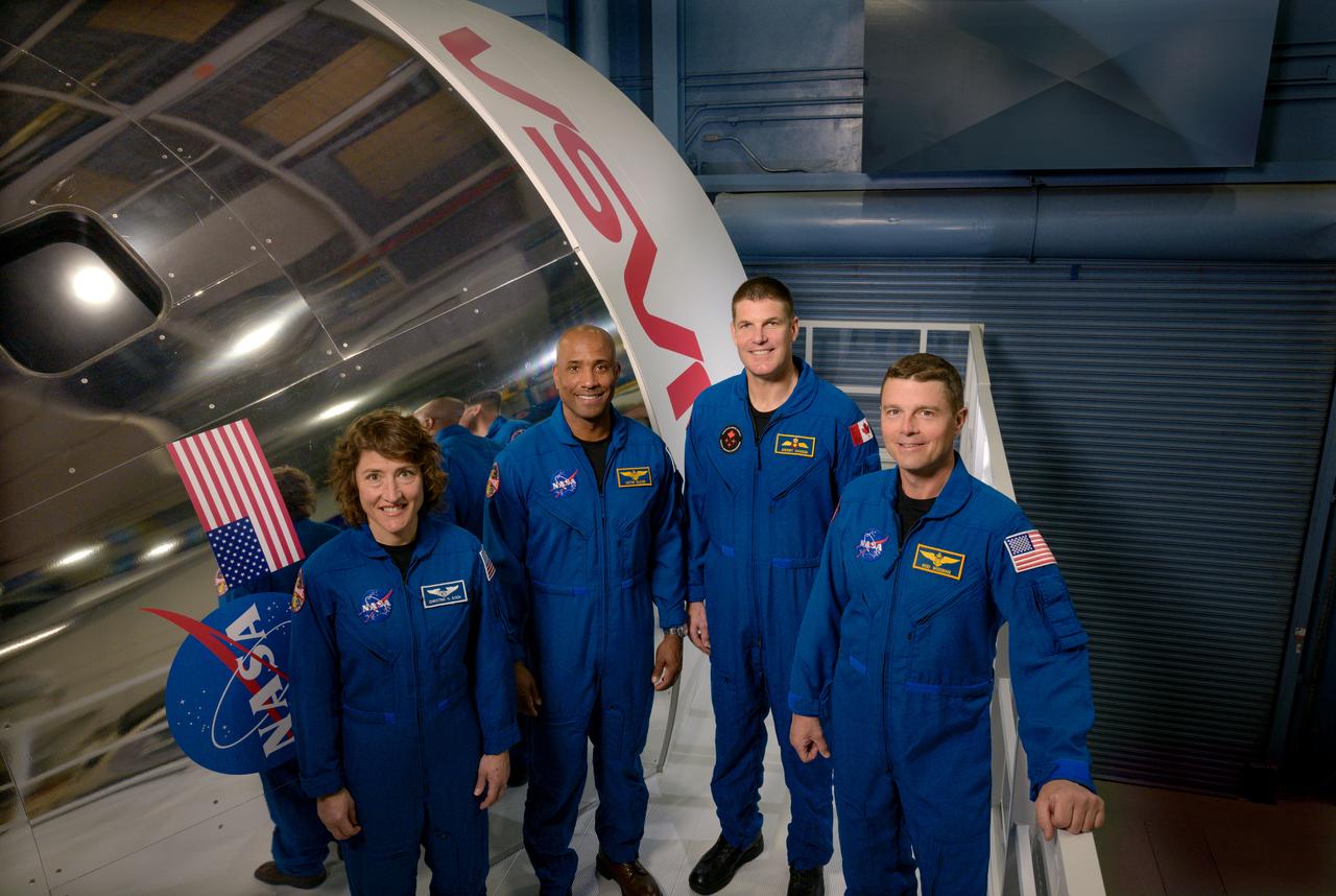
NASA astronauts Reid Wiseman, Victor Glover, and Christina Hammock Koch, and CSA astronaut Jeremy Hansen were announced Monday, April 3 as the four astronauts who will venture around the Moon on Artemis II, the first crewed mission on NASA’s path to establishing a long-term presence at the Moon for science and exploration through Artemis. The crew assignments are as follows: Commander Reid Wiseman, Pilot Victor Glover, Mission Specialist 1 Christina Koch, Mission Specialist 2 Jeremy Hansen. Photographer: James Blair

NASA astronauts Reid Wiseman, Victor Glover, and Christina Hammock Koch, and CSA astronaut Jeremy Hansen were announced Monday, April 3 as the four astronauts who will venture around the Moon on Artemis II, the first crewed mission on NASA’s path to establishing a long-term presence at the Moon for science and exploration through Artemis. The crew assignments are as follows: Commander Reid Wiseman, Pilot Victor Glover, Mission Specialist 1 Christina Koch, Mission Specialist 2 Jeremy Hansen. Photographer: James Blair
Adolf Busemann, the German aerodynamicist who first expressed the advantages of wing sweep in a 1935 theoretical paper, came to work at Langley in May 1947 as a result of Operation Paperclip. Photograph published in Engineer in Charge: A History of the Langley Aeronautical Laboratory, 1917-1958 by James R. Hansen. Page 283.
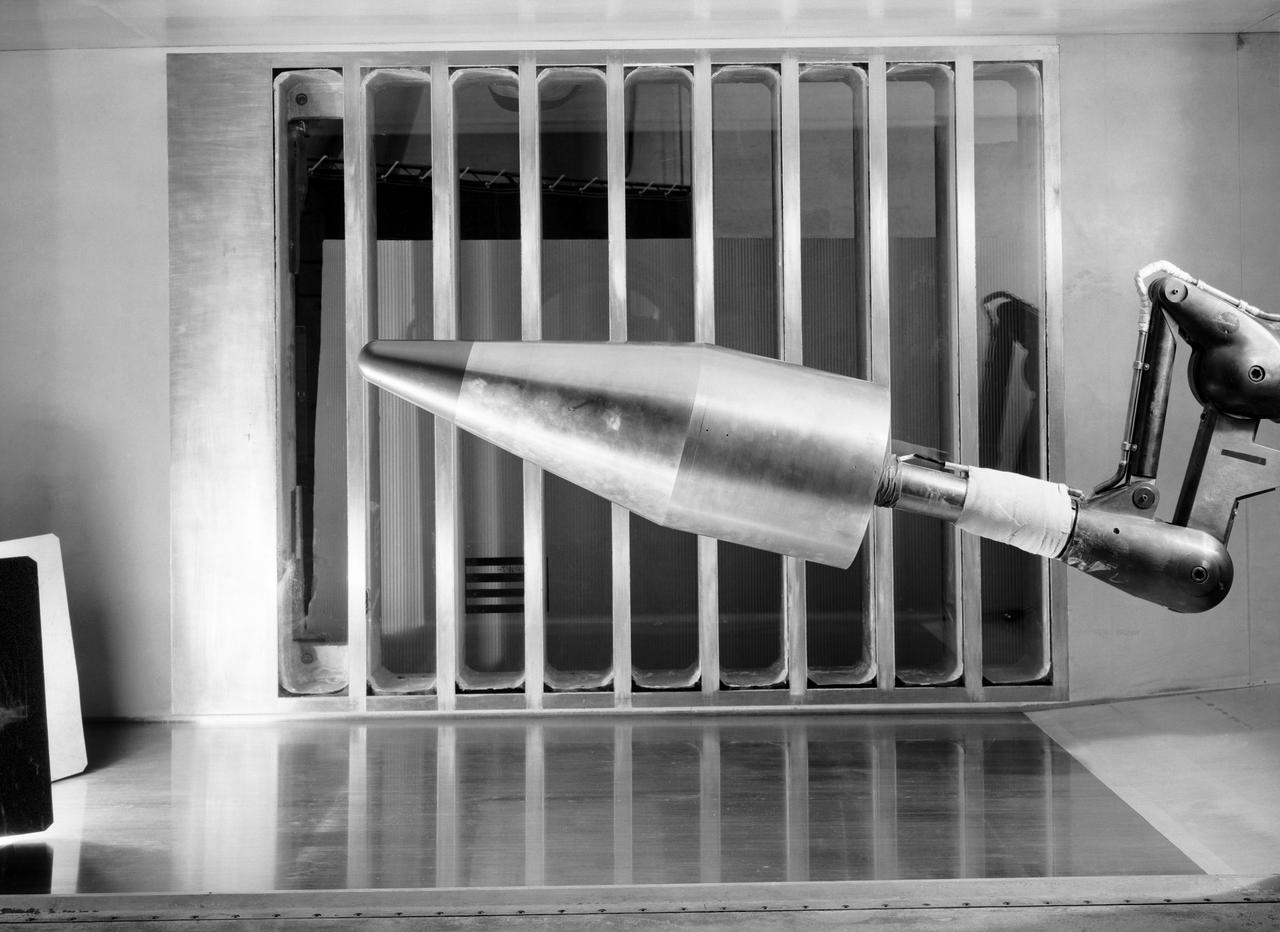
L57-700 In the reentry flight path of this nose cone model of a Jupiter Intermediate range ballistic missile (IRBM) was tested in the Unitary Plan Wind Tunnel. Photograph published in Engineer in Charge: A History of the Langley Aeronautical Laboratory, 1917-1958 by James R. Hansen. Page 475.
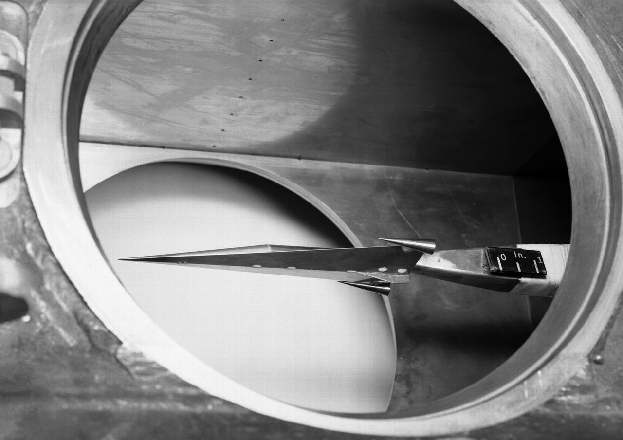
Hypersonic Boost Glider in 11 Inch Hypersonic Tunnel L57-1681 In 1957 Langley tested its HYWARDS design in the 11 Inch Hypersonic Tunnel. Photograph published in Engineer in Charge: A History of the Langley Aeronautical Laboratory, 1917-1958 by James R. Hansen. Page 369.
L65-5505 In the Gas Dynamics Laboratory, completed in 1951, researchers explored basic aerodynamic, heating and fluid-mechanical problems in the speed range from Mach 1.5 to Mach 8.0. Photograph published in Engineer in Charge: A History of the Langley Aeronautical Laboratory, 1917-1958 by James R. Hansen. Page 348.
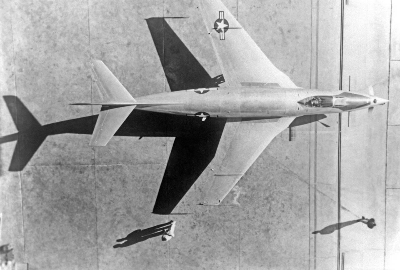
91,591 Overhead view. McDonnell XF-88B Experimental Jet Fighter. Langley used this aircraft in the mid-1950s to explore the potential of a supersonic propeller. Photographed in Engineer in Charge A History of the Langley Aeronautical Laboratory, 1917-1958 by James R. Hansen. Page 508. **Note see L57-2259 for eye level view.
Unidentified Pilot eyeballs his way to a docking by peering through the portal in his capsule. Photo published in Spaceflight Revolution, NASA Langley Research Center From Sputnik to Apollo. By James R. Hansen. NASA SP-4308, 1995, p. 372.
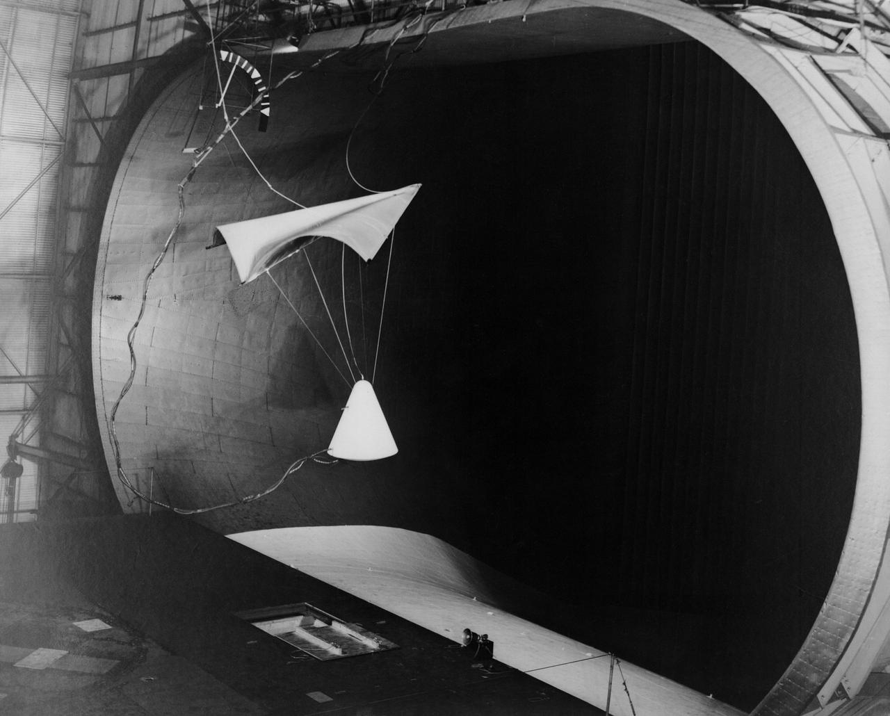
Image L61-4369 is available as an electronic file from the photo lab. See URL. -- Photographed on 06/30/1961. -- Test of parawing in Full Scale Wind Tunnel. -- Published in James R. Hansen, Spaceflight Revolution: NASA Langley Research Center From Sputnik to Apollo, (Washington: NASA, 1995), pp. 380-387.
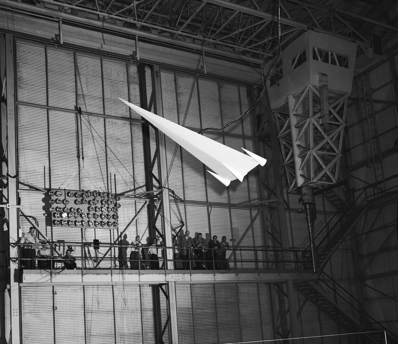
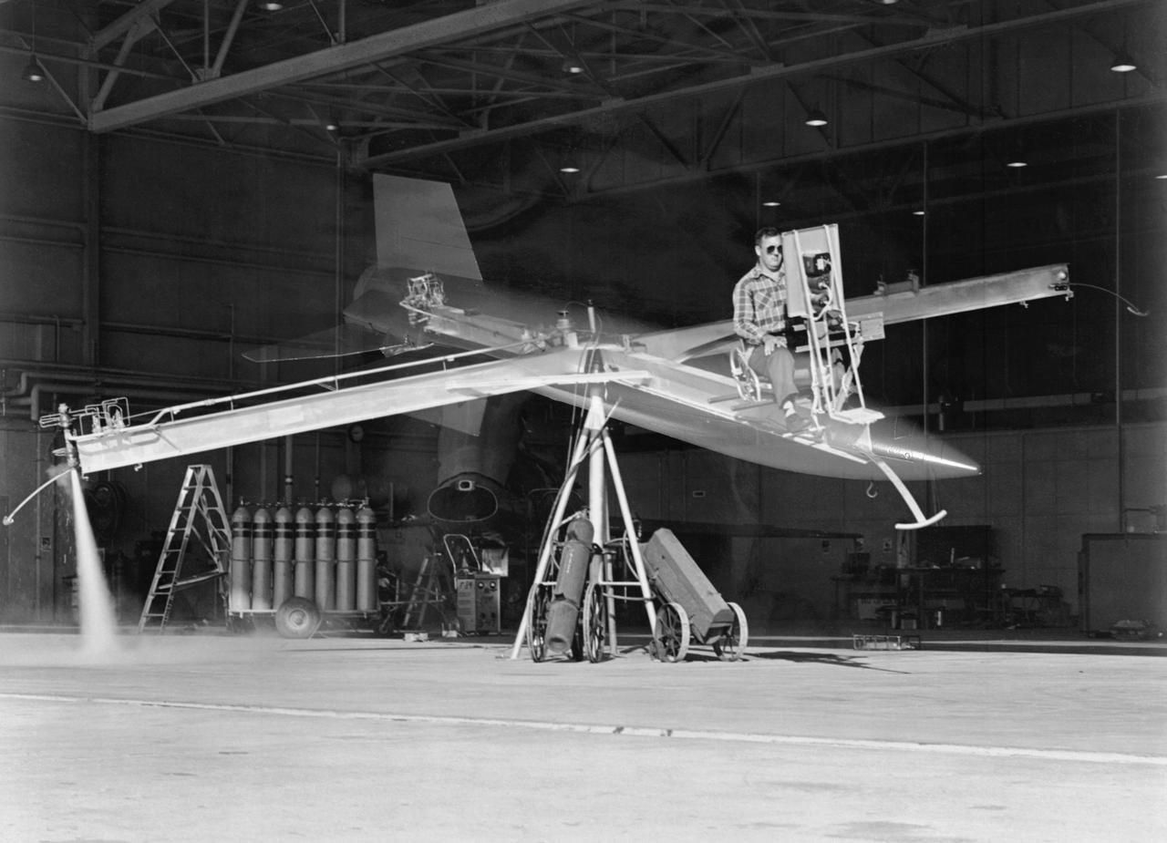
L57-1439 A model based on Langley s concept of a hypersonic glider was test flown on an umbilical cord inside the Full Scale Tunnel in 1957. Photograph published in Engineer in Charge: A History of the Langley Aeronautical Laboratory, 1917-1958 by James R. Hansen. Page 374.
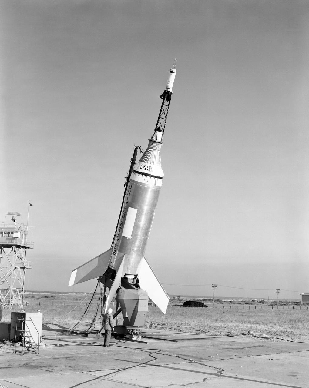
The Little Joe launch vehicle being readied for a test launch from Wallops in January 1960... Page 77. Photograph published in Winds of Change, 75th Anniversary NASA publication, by James Schultz. **note - see L59-5137 page 77 also. Photograph published in Engineer in Charge: A History of the Langley Aeronautical Laboratory, 1917-1958 by James R. Hansen. Page 389. ...was conceived by Langley engineers Max Faget and Paul Purser even before STG (Space Task Group) was organized.
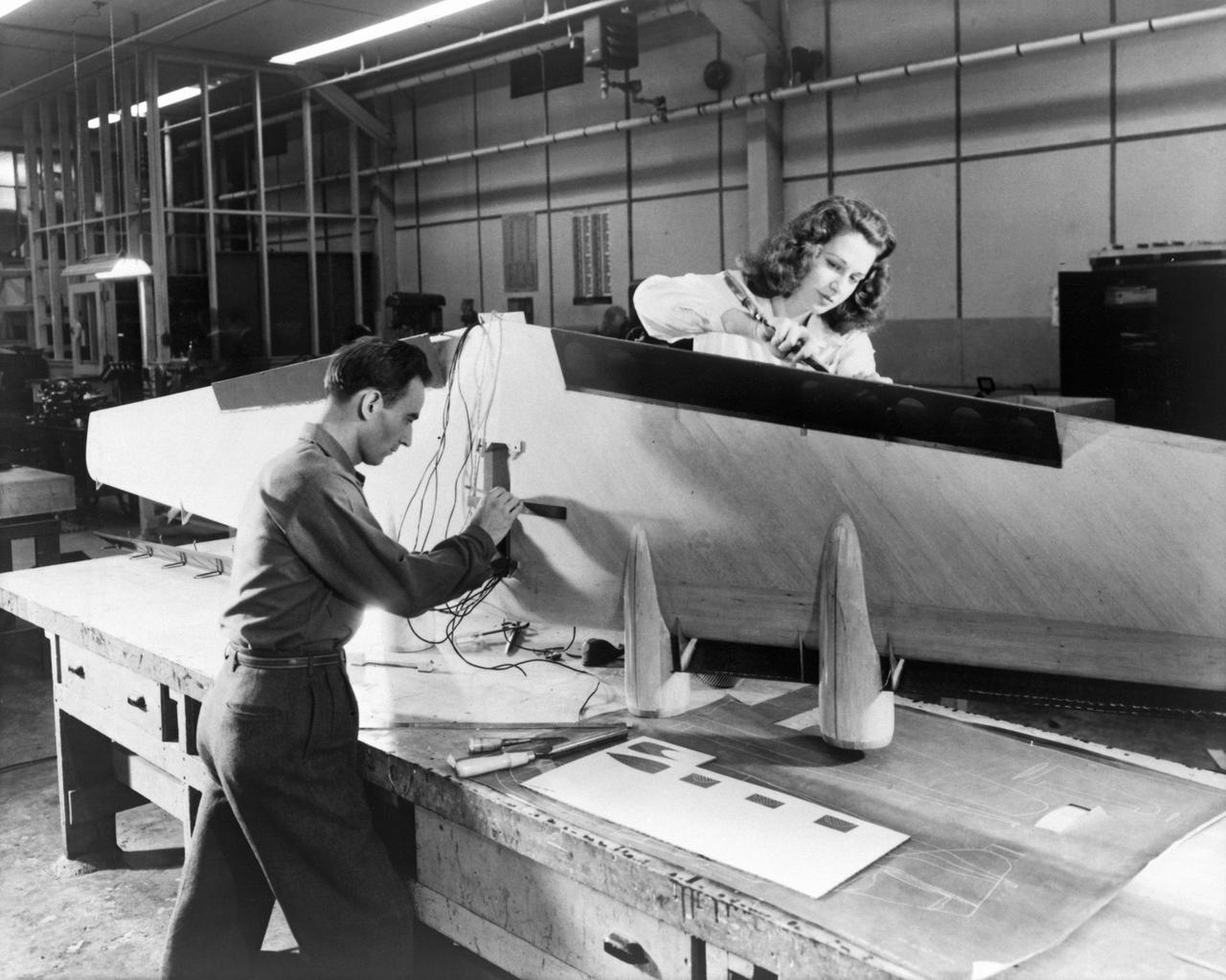
Technicians are pictured installing flaps and wiring on a flying-boat model, circa 1944 (page 47). Photograph published in Winds of Change, 75th Anniversary NASA publication, by James Schultz. Photograph also published in Engineer in Charge: A History of the Langley Aeronautical Laboratory, 1917-1958 by James R. Hansen (page 209). -- Photographed on: 04/24/1946.
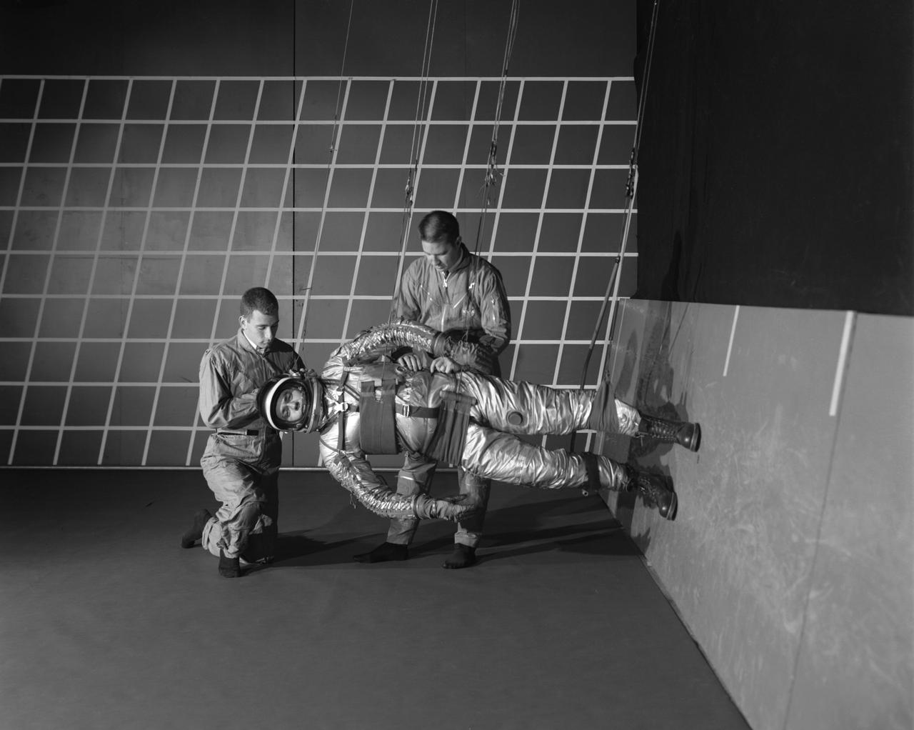
A test subject being suited up for studies on the Reduced Gravity Walking Simulator located in the hangar at Langley Research Center. The initial version of this simulator was located inside the hangar. Later a larger version would be located at the Lunar Landing Facility. The purpose of this simulator was to study the subject while walking, jumping or running. Researchers conducted studies of various factors such as fatigue limit, energy expenditure, and speed of locomotion. Francis B. Smith wrote in his paper "Simulators For Manned Space Research," "I would like to conclude this talk with a discussion of a device for simulating lunar gravity which is very effective and yet which is so simple that its cost is in the order of a few thousand dollars at most, rather than hundreds of thousands. With a little ingenuity, one could almost build this type simulator in his backyard for children to play on. The principle is ...if a test subject is suspended in a sling so that his body axis makes an angle of 9 1/2 degrees with the horizontal and if he then "stands" on a platform perpendicular to his body axis, the component of the earth's gravity forcing him toward the platform is one times the sine of 9 1/2 degrees or approximately 1/6 of the earth's normal gravity field. That is, a 180 pound astronaut "standing" on the platform would exert a force of only 30 pounds - the same as if he were standing upright on the lunar surface." -- Published in James R. Hansen, Spaceflight Revolution: NASA Langley Research Center From Sputnik to Apollo, NASA SP-4308; Francis B. Smith, "Simulators For Manned Space Research," Paper for 1966 IEEE International Convention, New York, NY, March 21-25, 1966
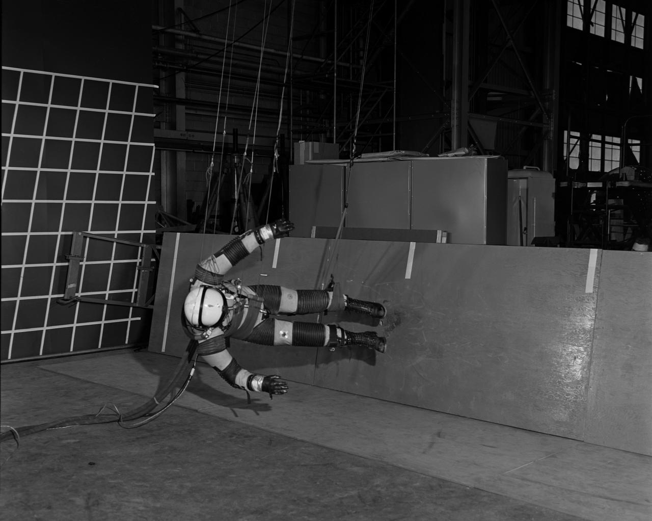
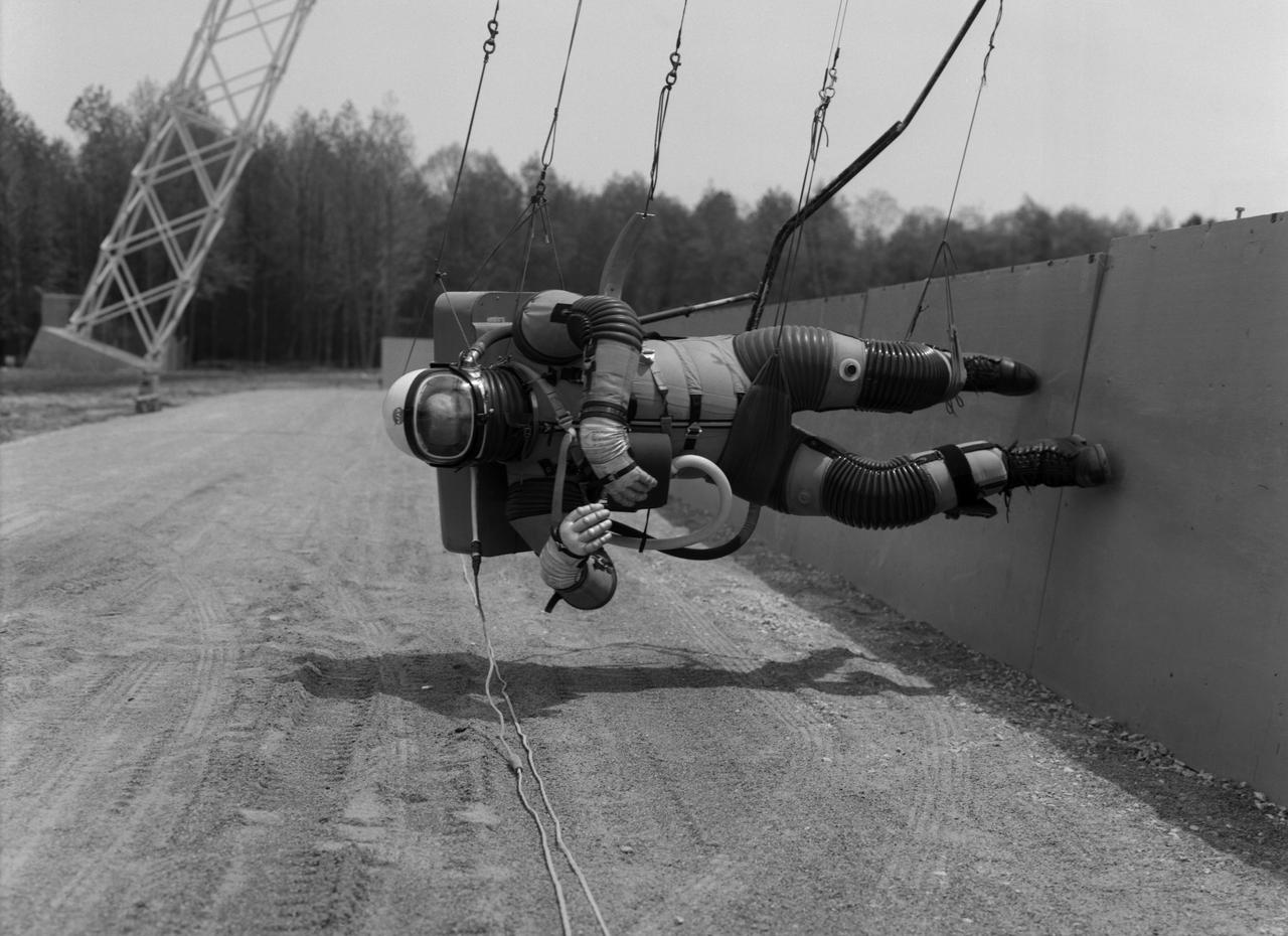
A "suited" test subject on the Reduced Gravity Walking Simulator located in the hangar at Langley Research Center. The initial version of this simulator was located inside the hangar. Later a larger version would be located at the Lunar Landing Facility. The purpose of this simulator was to study the subject while walking, jumping or running. Researchers conducted studies of various factors such as fatigue limit, energy expenditure, and speed of locomotion. Francis B. Smith wrote in "Simulators For Manned Space Research:" "The cables which support the astronaut are supported by an overhead trolley about 150 feet above the center line of the walkway and the support is arranged so that the subject is free to walk, run, jump, and perform other self-locomotive tasks in a more-or-less normal manner, even though he is constrained to move in one place." "The studies thus far show that an astronaut should have no particular difficulty in walking in a pressurized space suit on a hard lunar surface. Rather, the pace was faster and the suit was found to be more comfortable and less fatiguing under lunar "g" than under earth "g." When the test subject wished to travel hurriedly any appreciable distance, a long loping gait at about 10 feet per second was found to be most comfortable." -- Published in James R. Hansen, Spaceflight Revolution: NASA Langley Research Center From Sputnik to Apollo, (Washington: NASA, 1995), p. 377; Francis B. Smith, "Simulators For Manned Space Research," Paper for 1966 IEEE International Convention, New York, NY, March 21-25, 1966.

Astronaut Roger Chaffee on the Reduced Gravity Walking Simulator located at the Lunar Landing Facility. The purpose of this simulator was to study the subject while walking, jumping or running. Researchers conducted studies of various factors such as fatigue limit, energy expenditure, and speed of locomotion. A.W. Vigil, described the simulator as follows: "When the astronauts land on the moon they will be in an unfamiliar environment involving, particularly, a gravitational field only one-sixth as strong as on earth. A novel method of simulating lunar gravity has been developed and is supported by a puppet-type suspension system at the end of a long pendulum. A floor is provided at the proper angle so that one-sixth of the subject's weight is supported by the floor with the remainder being supported by the suspension system. This simulator allows almost complete freedom in vertical translation and pitch and is considered to be a very realistic simulation of the lunar walking problem. For this problem this simulator suffers only slightly from the restrictions in lateral movement it puts on the test subject. This is not considered a strong disadvantage for ordinary walking problems since most of the motions do, in fact, occur in the vertical plane. However, this simulation technique would be severely restrictive if applied to the study of the extra-vehicular locomotion problem, for example, because in this situation complete six degrees of freedom are rather necessary. This technique, in effect, automatically introduces a two-axis attitude stabilization system into the problem. The technique could, however, be used in preliminary studies of extra-vehicular locomotion where, for example, it might be assumed that one axis of the attitude control system on the astronaut maneuvering unit may have failed." -- Published in James R. Hansen, Spaceflight Revolution: NASA Langley Research Center From Sputnik to Apollo, NASA SP-4308, p. 377; A.W. Vigil, "Discussion of Existing and Planned Simulators for Space Research," Paper presented at Conference on the Role of Simulation in Space Technology," Blacksburg, VA, August 17-21, 1964.
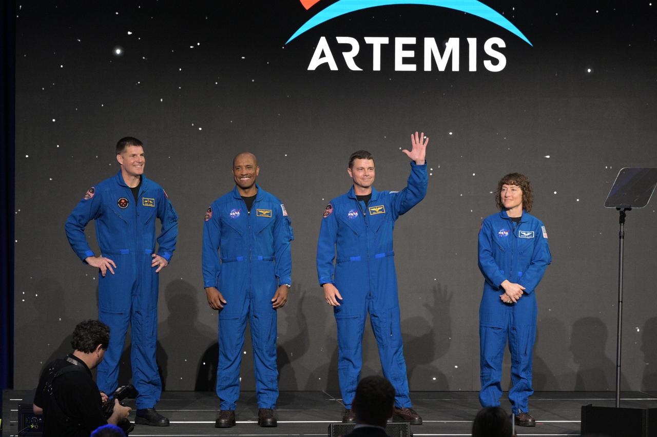
jsc2023e017059 (April 4, 2023) -- NASA astronauts Reid Wiseman, Victor Glover and Christina Koch, and CSA (Canadian Space Agency) astronaut Jeremy Hansen, are announced as members of the Artemis II crew that will travel around the Moon during a Monday, April 3, 2023, crew announcement news conference at Ellington Field near NASA’s Johnson Space Center. The crew is comprised of Commander Reid Wiseman, Pilot Victor Glover, and Mission Specialists Christina Koch and Jeremy Hansen. The four astronauts will venture around the Moon on Artemis II, the first crewed mission on NASA’s path to establishing a long-term presence at the Moon for science and exploration through Artemis. Photo by James Blair.
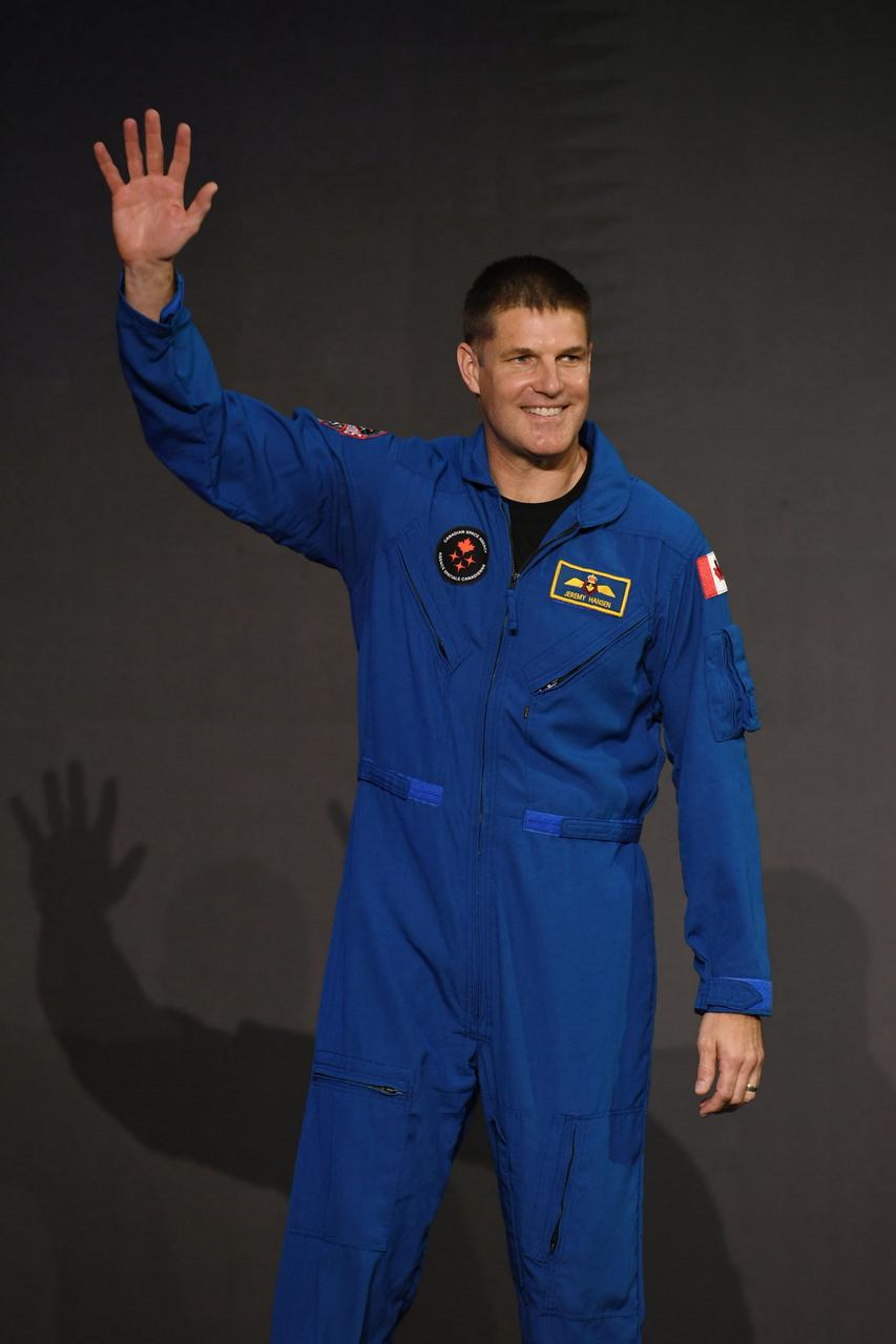
jsc2023e017056 (April 4, 2023) -- CSA (Canadian Space Agency) astronaut Jeremy Hansen is announced as one of four members of the Artemis II crew that will travel around the Moon. Hansen was joined by NASA astronauts Reid Wiseman, Victor Glover, and Christina Koch, during a Monday, April 3, 2023, crew announcement news conference at Ellington Field near NASA's Johnson Space Center. The crew is comprised of Commander Reid Wiseman, Pilot Victor Glover, and Mission Specialists Christina Koch and Jeremy Hansen. The four astronauts will venture around the Moon on Artemis II, the first crewed mission on NASA's path to establishing a long-term presence at the Moon for science and exploration through Artemis. Photo by James Blair.
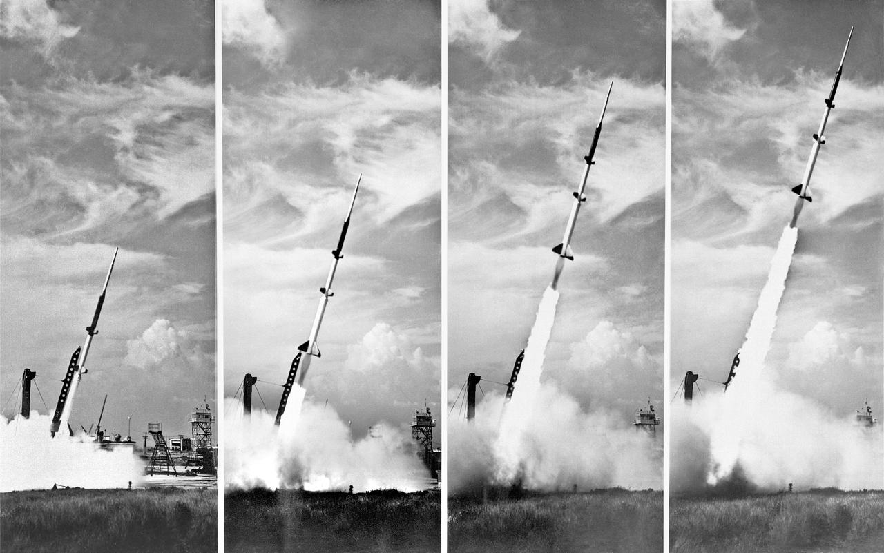
**Note also copied and numbered as L90-3749. -- L57-4827 caption: Take off of a five-stage missile research rocket from Wallops Island in 1957. The first two stages propelled the model to about 100,000 feet the last three stages were fired on a descending path to simulate the reentry conditions of ballistic missiles. -- Photograph published in Winds of Change, 75th Anniversary NASA publication (page 72), by James Schultz. -- Photograph also published in Engineer in Charge: A History of the Langley Aeronautical Laboratory, 1917-1958 by James R. Hansen (page 380).
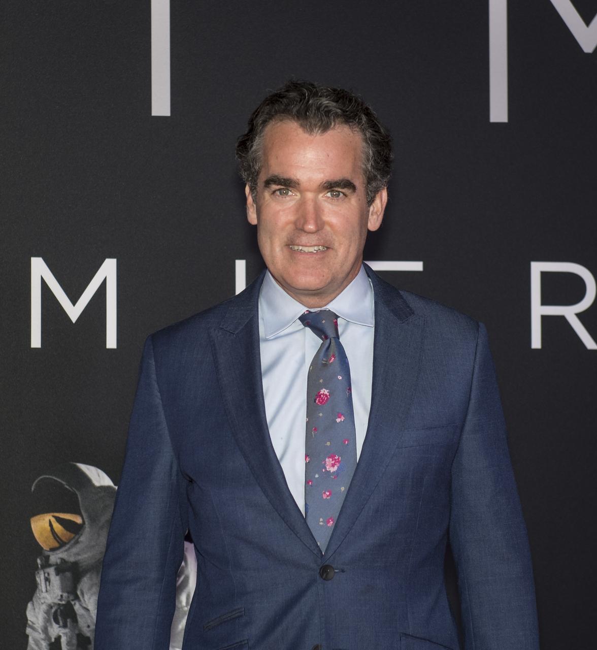
American actor Brian D'Arcy James arrives on the red carpet for the premiere of the film "First Man" at the Smithsonian National Air and Space Museum Thursday, Oct. 4, 2018 in Washington. The film is based on the book by Jim Hansen, and chronicles the life of NASA astronaut Neil Armstrong from test pilot to his historic Moon landing. Photo Credit: (NASA/Aubrey Gemignani)
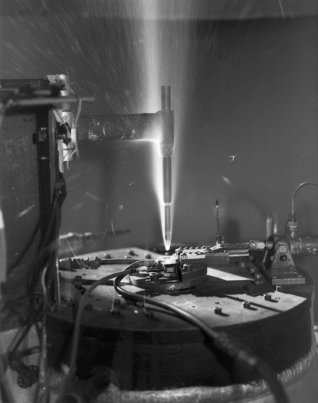
L57-5383 Hot-air jets employing ceramic heat exchangers played an important role at Langley in the study of materials for ballistic missile nose cones and re-entry vehicles. Here a model is being tested in one of theses jets at 4000 degrees Fahrenheit in 1957. Photograph published in Engineer in Charge: A History of the Langley Aeronautical Laboratory, 1917-1958 by James R. Hansen. Page 477.
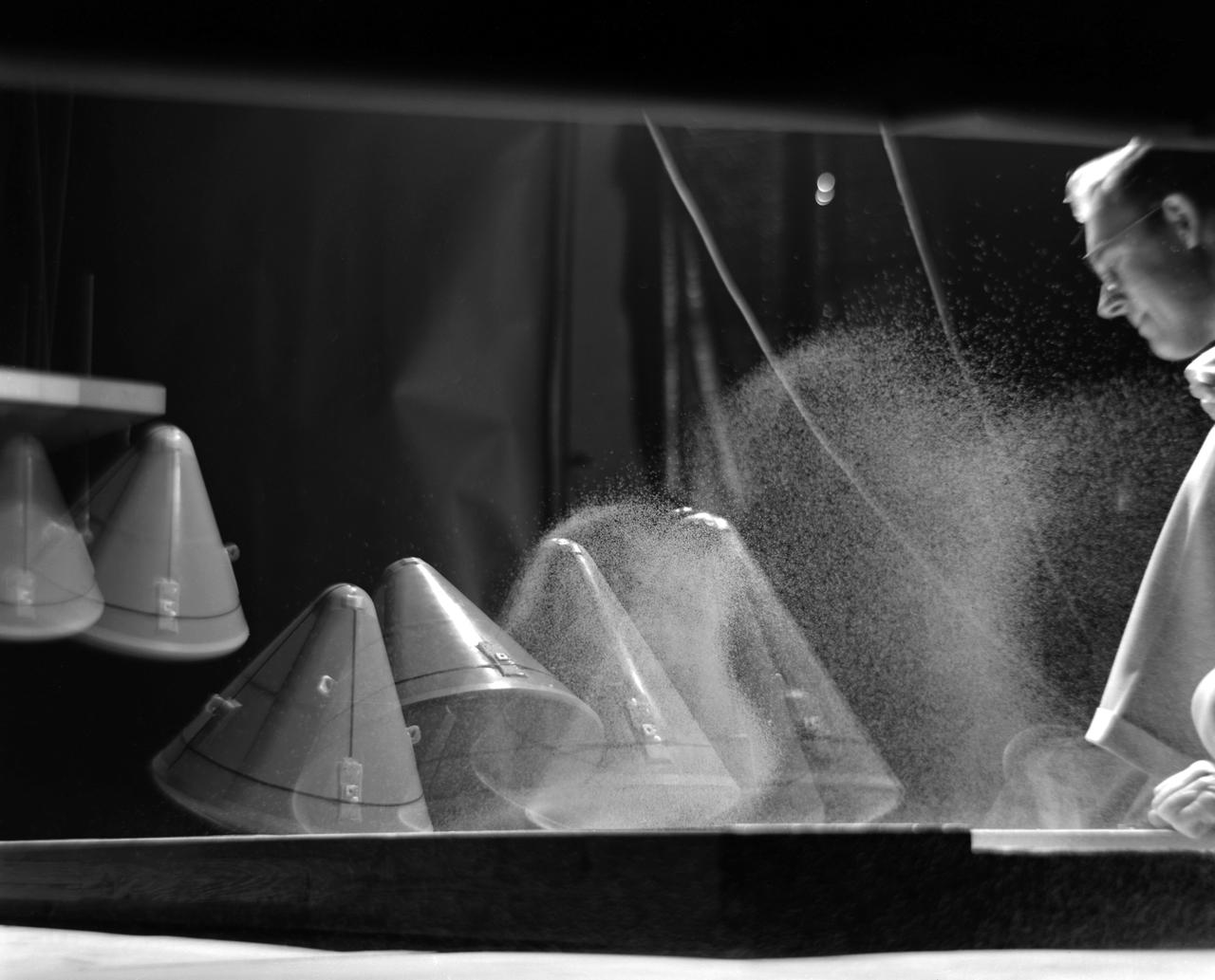
Image L61-8036 is available as an electronic file from the photo lab. See URL. -- Photographed on 12/05/1961. -- Multiple exposure of an impact test of the Apollo command module. In this test the Apollo capsule was tested making a sand landing. -- Published in James R. Hansen, Spaceflight Revolution: NASA Langley Research Center From Sputnik to Apollo, (Washington: NASA, 1995), pp. 361-366.
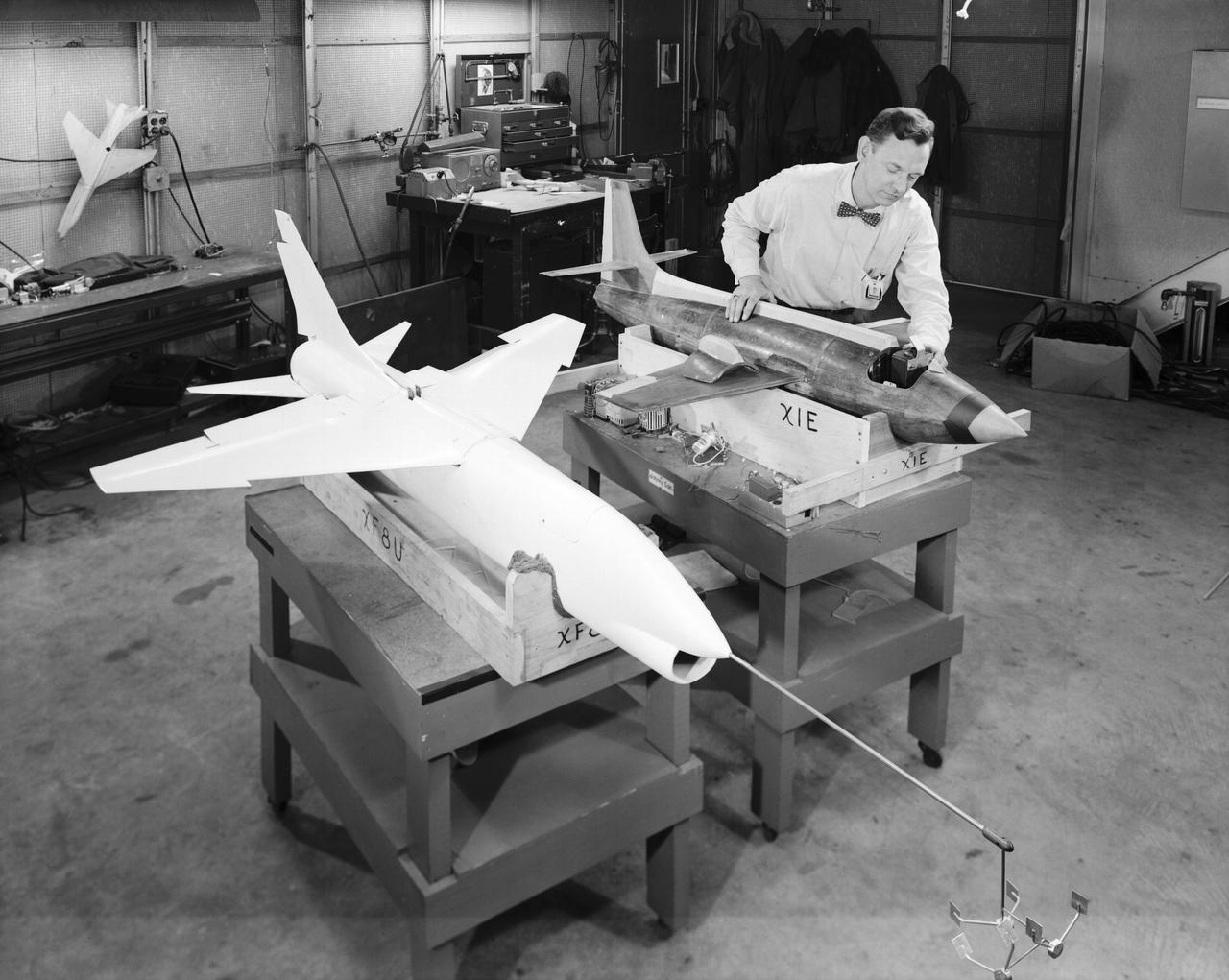
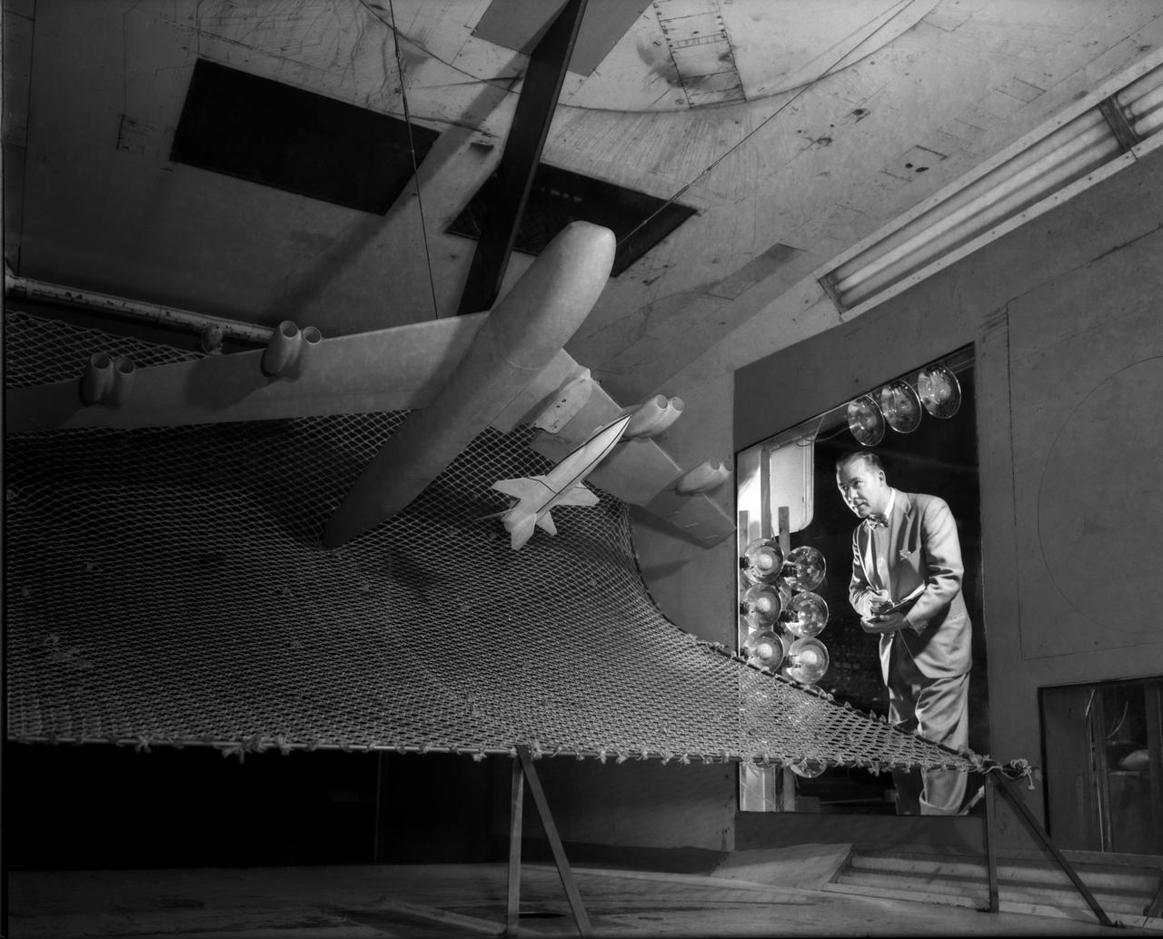
L57-660 A technician prepares dynamic models of the Bell X-1E and the Vought XF-8U Crusader for wind tunnel testing in 1957. The Crusader was then the Navy's fastest aircraft- maximum speed Mach 1.75 at 35,000 Feet. Photograph published in Engineer in Charge: A History of the Langley Aeronautical Laboratory, 1917-1958 by James R. Hansen. Page 307.
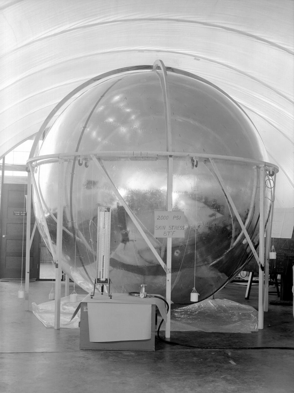
Photographed in 1960. -- Skin Stress Test of the 12-foot satellite built as a prototype of the full-scale Echo satellite. The 12-foot diameter of the sphere was chosen because that was the ceiling height in the Langley model shop. The proposal to build the 12-foot satellite was made in November 1957. -- Published in James R. Hansen, Spaceflight Revolution: NASA Langley Research Center From Sputnik to Apollo, NASA SP-4308, pp. 170-171.
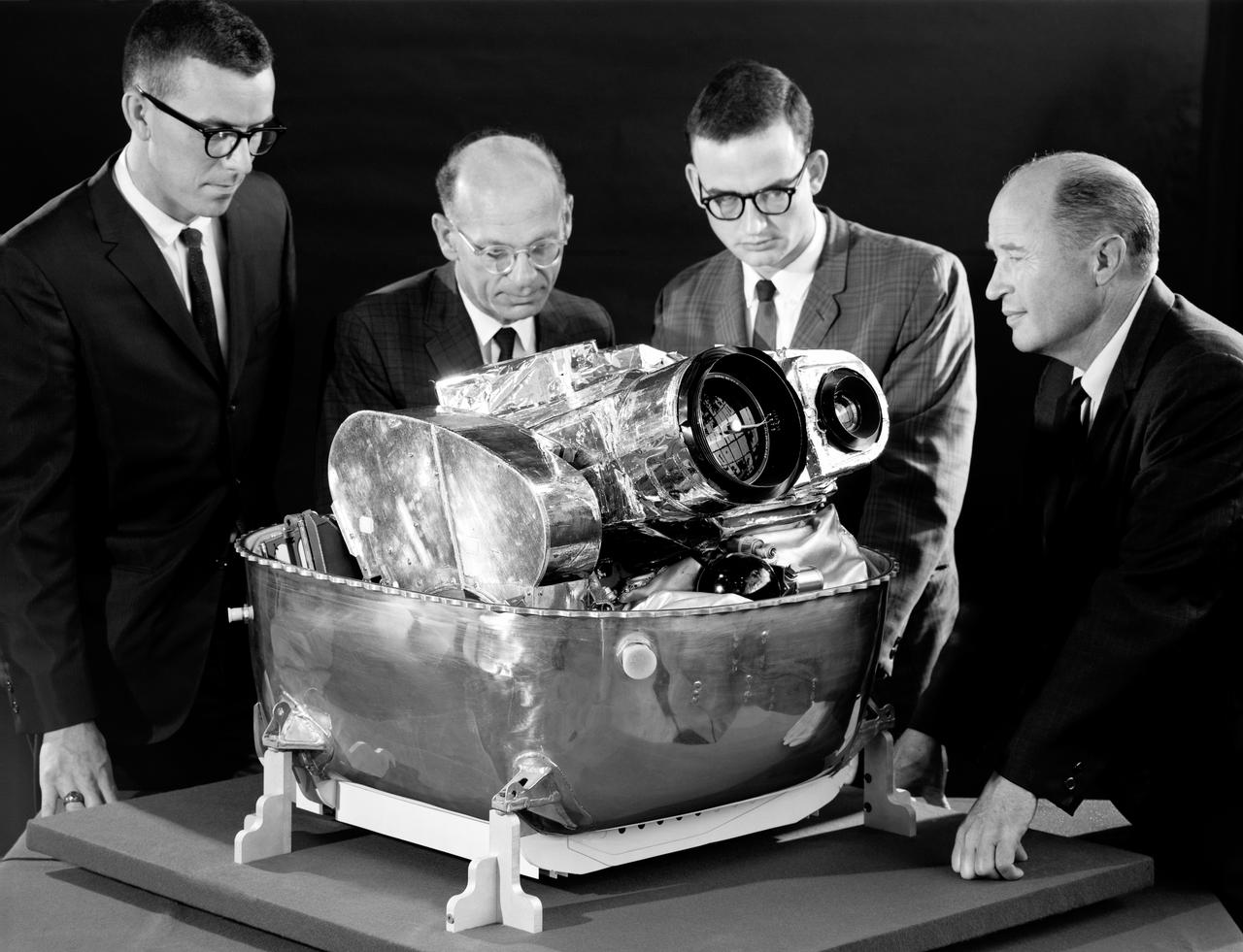
Lunar Orbiter was essentially a flying camera. The payload structure was built around a pressurized shell holding Eastman Kodak s dual-imaging photographic system, which used a camera with wide-angle and telephoto lenses that could simultaneously take two kinds of pictures on the same film. Men in in the picture are: Right to left Cliff Nelson, Calvin Broome, Israel Taback and Joe Mooreman. -- Published in James R. Hansen, Spaceflight Revolution: NASA Langley Research Center From Sputnik to Apollo, NASA SP-4308, p. 329.
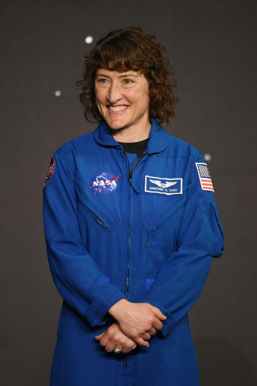
jsc2023e017055 (April 4, 2023) -- NASA astronaut Christina Koch is announced as one of four members of the Artemis II crew that will travel around the Moon. Koch was joined by fellow NASA astronauts Reid Wiseman, Victor Glover, and, and CSA (Canadian Space Agency) astronaut Jeremy Hansen during a Monday, April 3, 2023, crew announcement news conference at Ellington Field near NASA’s Johnson Space Center. The crew is comprised of Commander Reid Wiseman, Pilot Victor Glover, and Mission Specialists Christina Koch and Jeremy Hansen. The four astronauts will venture around the Moon on Artemis II, the first crewed mission on NASA’s path to establishing a long-term presence at the Moon for science and exploration through Artemis. Photo by James Blair.

jsc2023e017057 (April 4, 2023) -- NASA astronaut Victor Glover is announced as one of four members of the Artemis II crew that will travel around the Moon. Glover was joined by fellow NASA astronauts Reid Wiseman and Christina Koch, and CSA (Canadian Space Agency) astronaut Jeremy Hansen during a Monday, April 3, 2023, crew announcement news conference at Ellington Field near NASA’s Johnson Space Center. The crew is comprised of Commander Reid Wiseman, Pilot Victor Glover, and Mission Specialists Christina Koch and Jeremy Hansen. The four astronauts will venture around the Moon on Artemis II, the first crewed mission on NASA’s path to establishing a long-term presence at the Moon for science and exploration through Artemis. Photo by James Blair.
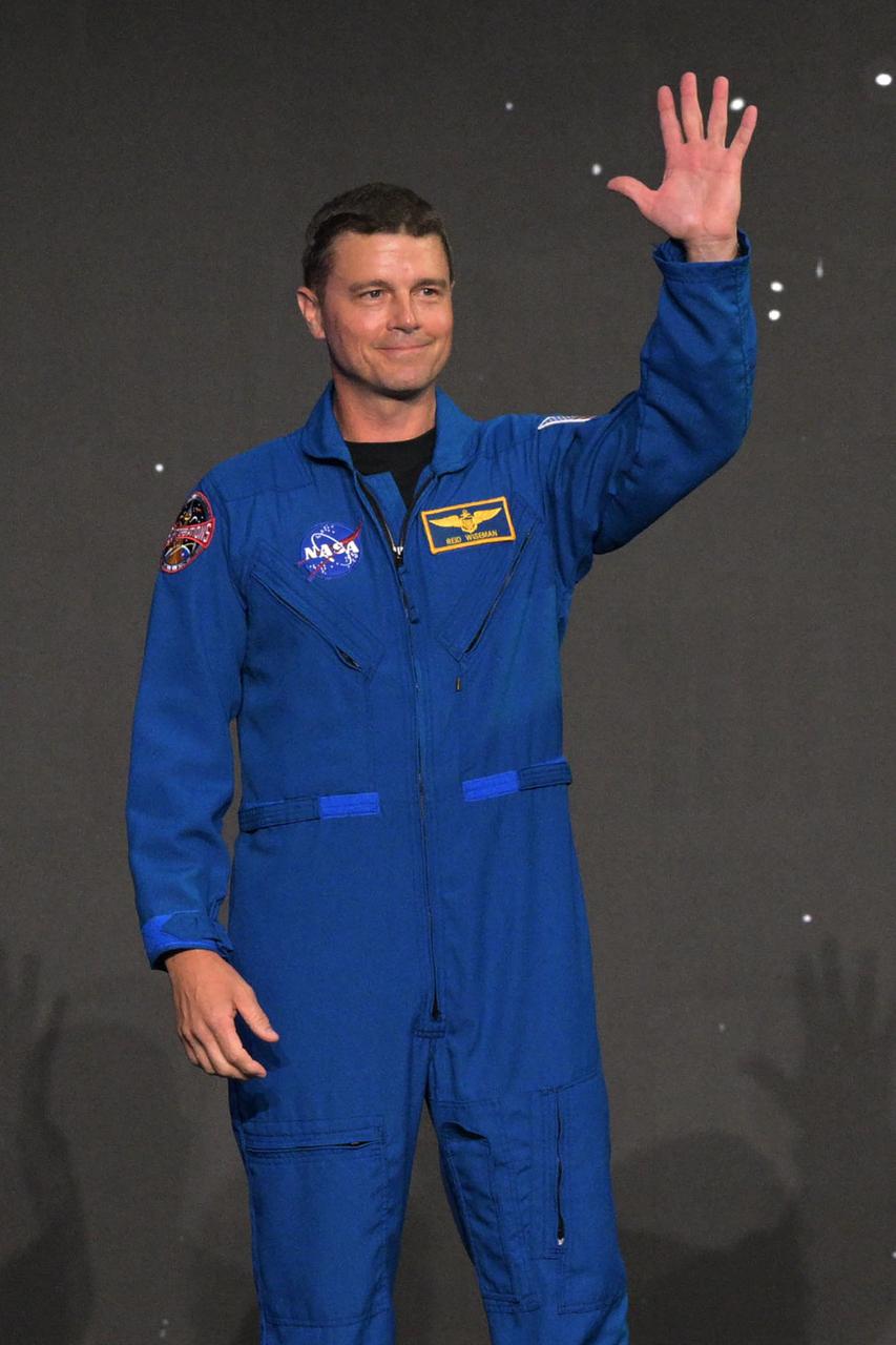
jsc2023e017058 (April 4, 2023) -- NASA astronaut Reid Wiseman is announced as one of four members of the Artemis II crew that will travel around the Moon. Wiseman was joined by fellow NASA astronauts Victor Glover and Christina Koch, and CSA (Canadian Space Agency) astronaut Jeremy Hansen during a Monday, April 3, 2023, crew announcement news conference at Ellington Field near NASA’s Johnson Space Center. The crew is comprised of Commander Reid Wiseman, Pilot Victor Glover, and Mission Specialists Christina Koch and Jeremy Hansen. The four astronauts will venture around the Moon on Artemis II, the first crewed mission on NASA’s path to establishing a long-term presence at the Moon for science and exploration through Artemis. Photo by James Blair.
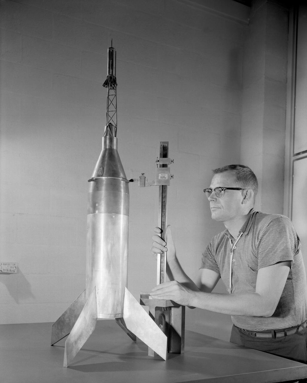
Publicity photograph of a technician measuring a wind tunnel model of the Little Joe test vehicle. Joseph Shortal noted that (vol. 3, p. 29): The largest project at Wallops in support of Mercury was the Little Joe project, designed to qualify the abort-escape system under flight conditions. James Hansen (p. 47) writes: STG engineers Max Faget and Paul Purser, then of Langley's PARD, had conceived Little Joe as a space capsule test vehicle even before the establishment of NASA and the formation of the STG. Girlruth understood the importance of the Little Joe tests: We had to be sure there were no serious performance and operational problems that we had simply not thought of in such a new and radical type of flight vehicle. -- Published in James R. Hansen, Spaceflight Revolution: NASA Langley Research Center From Sputnik to Apollo, (Washington: NASA, 1995), p. 47 Joseph A. Shortal, History of Wallops Station: Origins and Activities Through 1949, (Wallops Island, VA: National Aeronautics and Space Administration, Wallops Station, nd), Comment Edition.
A one-twentieth scale model of the X-15 originally suspended beneath the wing of a B-52 is observed by a scientist of the National Aeronautics and Space Administration (NASA) as it leaves the bomber model in tests to determine the release characteristics and drop motion of the research airplane. Caption: The aerodynamics of air launching the North American X-15 being investigated in the 300MPH Low Speed 7x10 Tunnel, about 1957. Photograph published in Engineer in Charge: A History of the Langley Aeronautical Laboratory, 1917-1958 by James R. Hansen. Page 366. Photograph also published in Sixty Years of Aeronautical Research 1917-1977 By David A. Anderton. A NASA publication. Page 49.
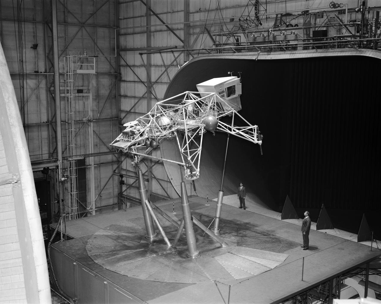
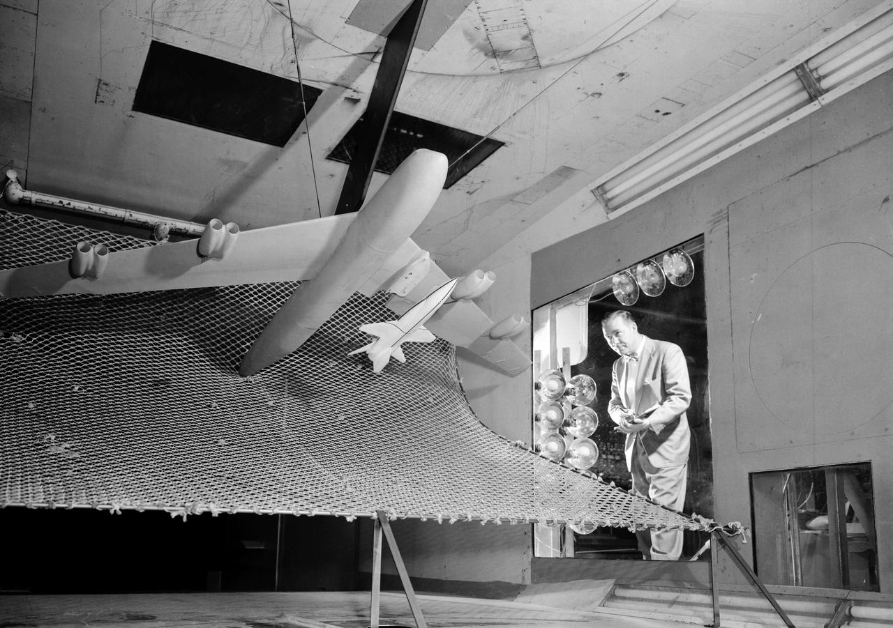
Concept model of the Lunar Excursion Module tested in the Full-Scale wind tunnel. -- Published in James R. Hansen, Spaceflight Revolution: NASA Langley Research Center From Sputnik to Apollo, (Washington: NASA, 1995), p. 356.-L69-670 Bell Lunar Landing Training Vehicle (LLTV): Following the crash of a sister Lunar Landing Training Vehicle at Ellington Field in Houston, Texas, the LLTV NASA 952 was sent from Houston to Langley for tests in the 30 x 60 Full Scale Tunnel. The LLTV was returned to Houston for further training use a short time later. NASA 952 is now on exhibit at the Johnson Space Center in Houston, Texas.
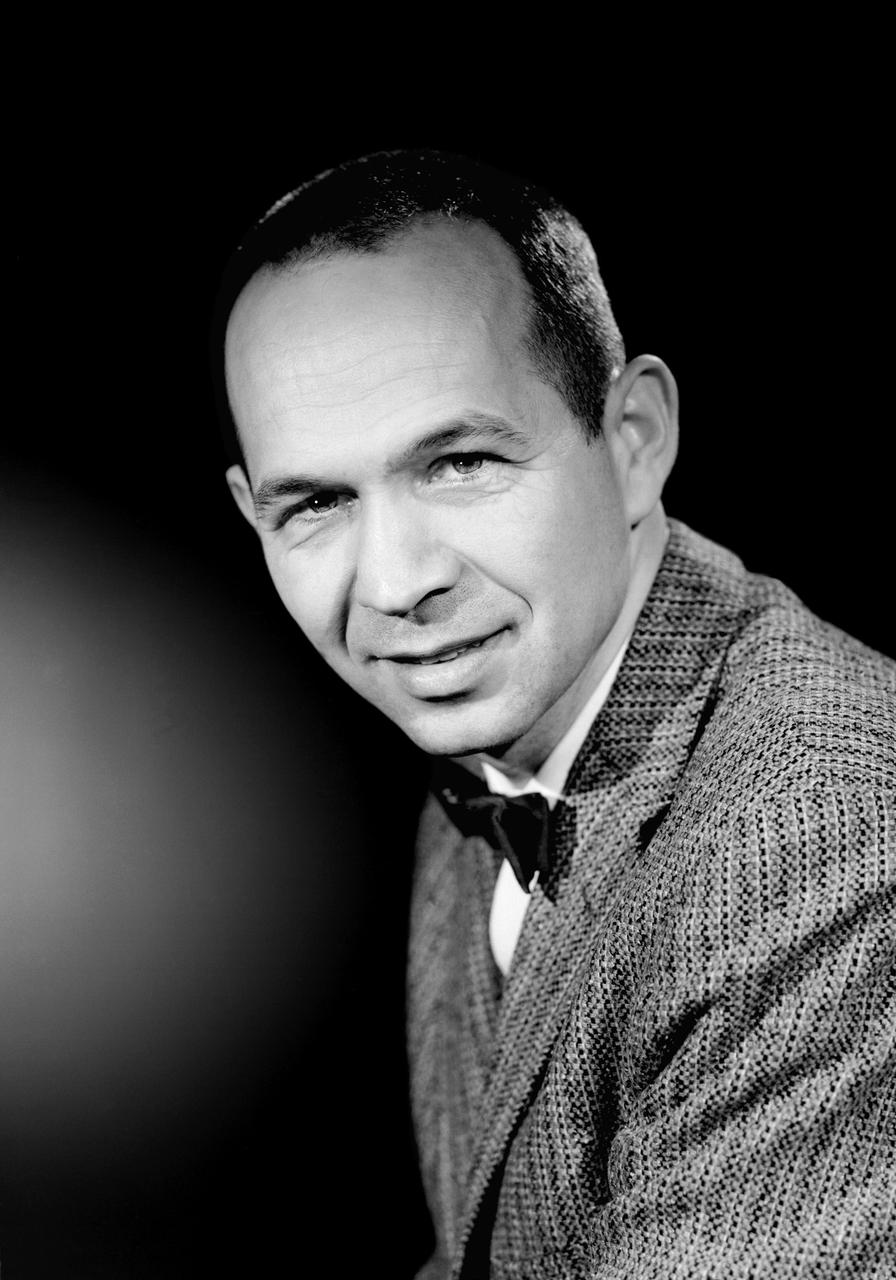
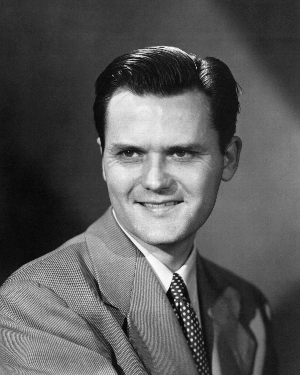
L59-1497-6 Maxime A. Faget was born in British Honduras in 1921, the son of an honored physician of the U.S. Public Health Service. In 1943 he earned a B.S. in mechanical engineering from Louisiana State University. After service as a navy submarine officer, he joined the Langley staff in 1946 as a member of the Pilotless Aircraft Research Division. His early work for PARD involved the invention of choking inlets for ramjets and a flight Mach meter. Photograph published in Engineer in Charge: A History of the Langley Aeronautical Laboratory, 1917-1958 by James R. Hansen. Page 379.
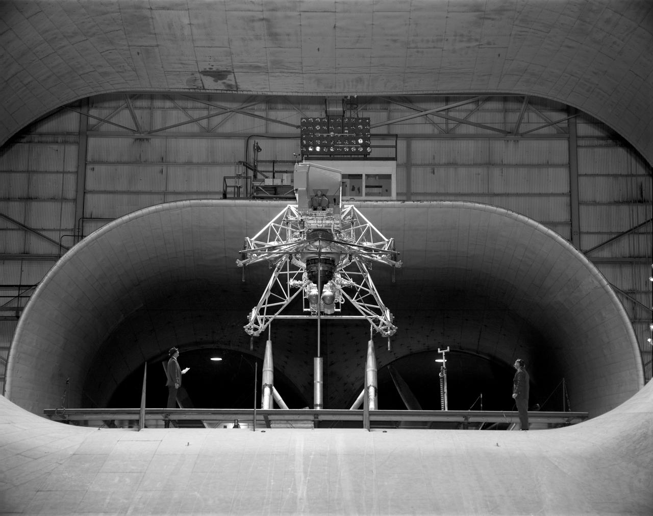
Concept model of the Lunar Excursion Module tested in the Full-Scale wind tunnel. -- Published in James R. Hansen, Spaceflight Revolution: NASA Langley Research Center From Sputnik to Apollo, (Washington: NASA, 1995), p. 356.-L69-670 Bell Lunar Landing Training Vehicle (LLTV): Following the crash of a sister Lunar Landing Training Vehicle at Ellington Field in Houston, Texas, the LLTV NASA 952 was sent from Houston to Langley for tests in the 30 x 60 Full Scale Tunnel. The LLTV was returned to Houston for further training use a short time later. NASA 952 is now on exhibit at the Johnson Space Center in Houston, Texas.
A one-twentieth scale model of the X-15 originally suspended beneath the wing of a B-52 is observed by a scientist of the National Aeronautics and Space Administration (NASA) as it leaves the bomber model in tests to determine the release characteristics and drop motion of the research airplane. Caption: The aerodynamics of air launching the North American X-15 being investigated in the 300MPH Low Speed 7x10 Tunnel, about 1957. Photograph published in Engineer in Charge: A History of the Langley Aeronautical Laboratory, 1917-1958 by James R. Hansen. Page 366. Photograph also published in Sixty Years of Aeronautical Research 1917-1977 By David A. Anderton. A NASA publication. Page 49.
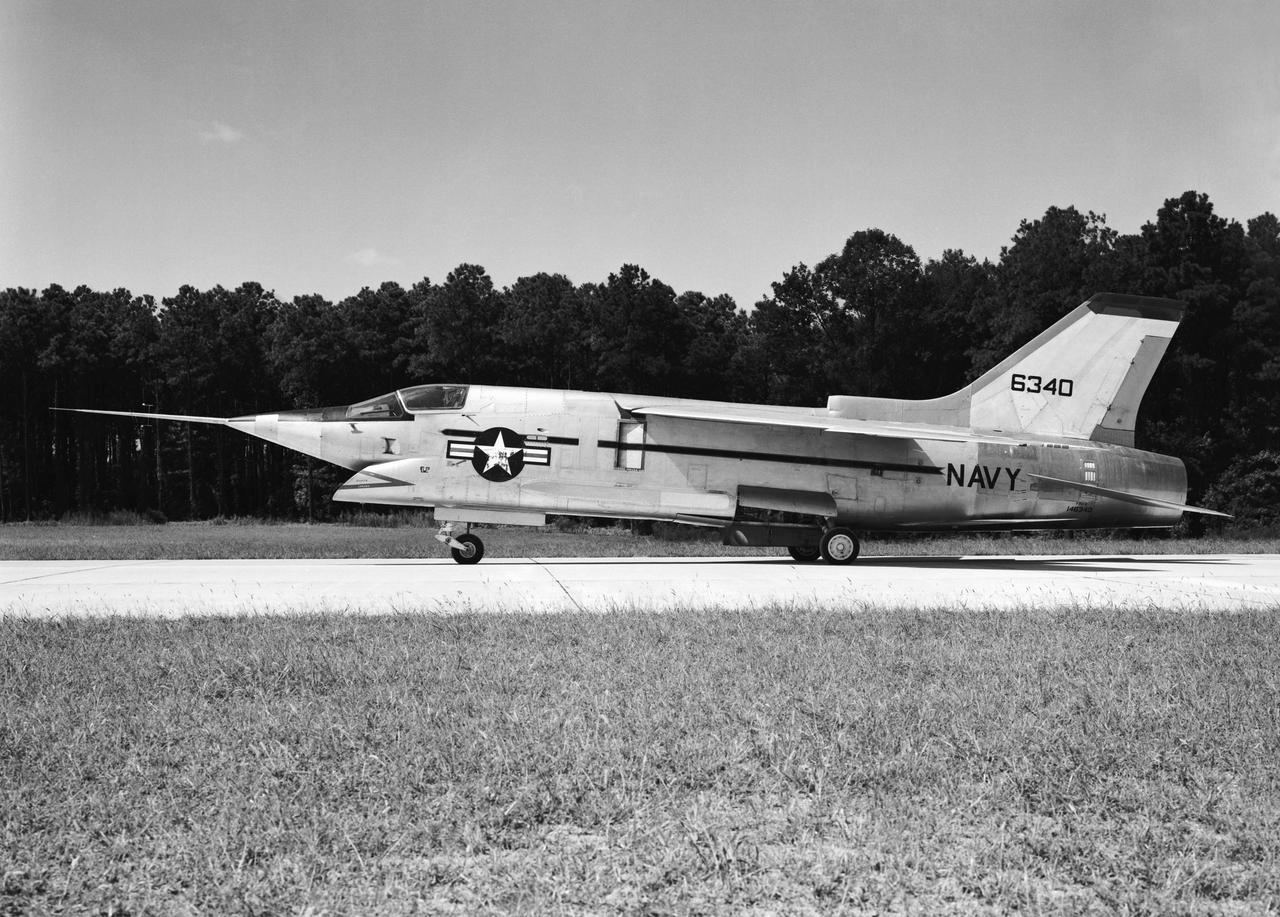
Crusader on runway. Navy aircraft number 6340. L59-6101 caption: The Navy's Vought XF8U-3 Supersonic Fighter was an entirely new design as compared to the earlier F8U Crusader series. This jet plane lost in competition with the McDonnell F4H, however, and was never put into production. Langley used the XF8U-3 in some of the first flight measurements of sonic boom intensity. Photograph published in Engineer in Charge A History of the Langley Aeronautical Laboratory, 1917-1958 by James R. Hansen. Page 507. Caption: Chance Vought F8U-3 airplane used in sonic boom investigation at Wallops, June-August 1959. Photograph published in A New Dimension Wallops Island Flight Test Range: The First Fifteen Years by Joseph Shortal. A NASA publication. Page 672.
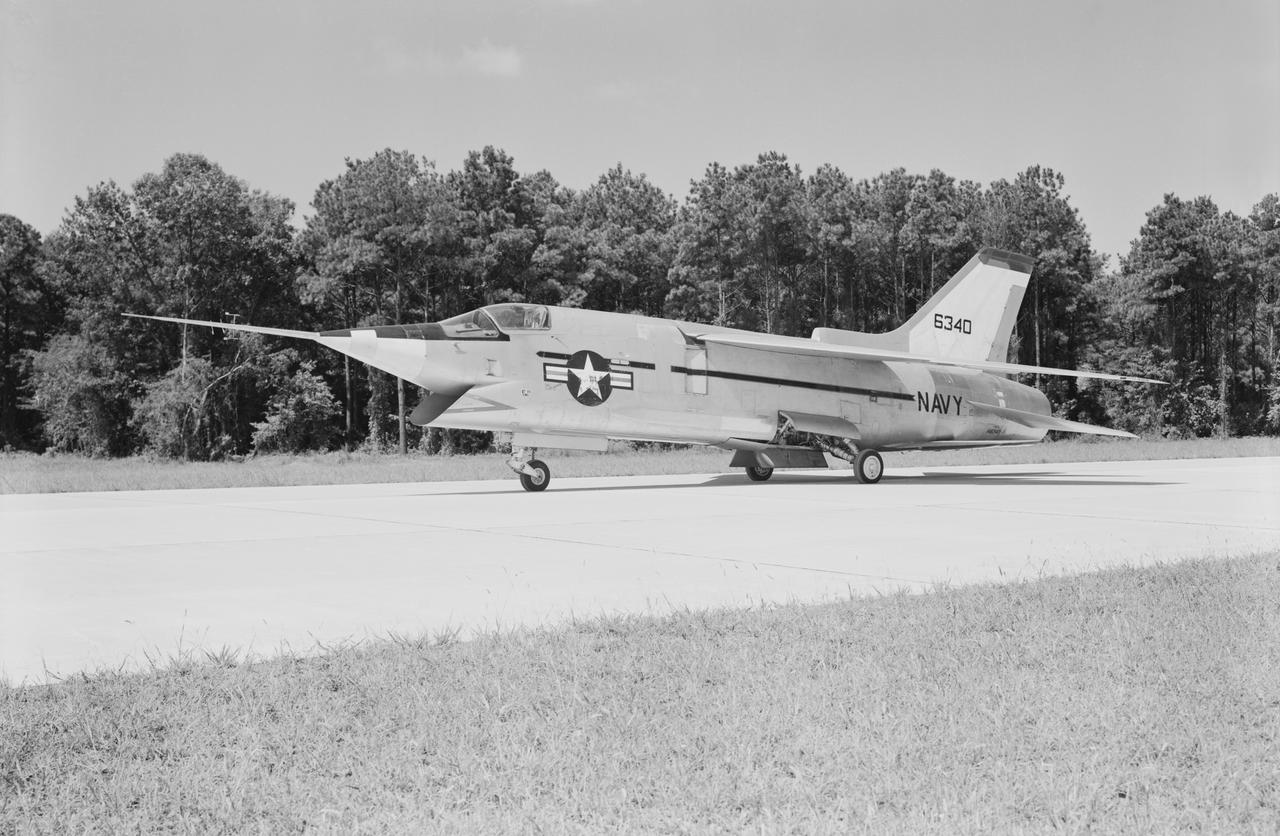
Crusader on runway. Navy aircraft number 6340. L59-6101 caption: The Navy's Vought XF8U-3 Supersonic Fighter was an entirely new design as compared to the earlier F8U Crusader series. This jet plane lost in competition with the McDonnell F4H, however, and was never put into production. Langley used the XF8U-3 in some of the first flight measurements of sonic boom intensity. Photograph published in Engineer in Charge A History of the Langley Aeronautical Laboratory, 1917-1958 by James R. Hansen. Page 507. Caption: Chance Vought F8U-3 airplane used in sonic boom investigation at Wallops, June-August 1959. Photograph published in A New Dimension Wallops Island Flight Test Range: The First Fifteen Years by Joseph Shortal. A NASA publication. Page 672.
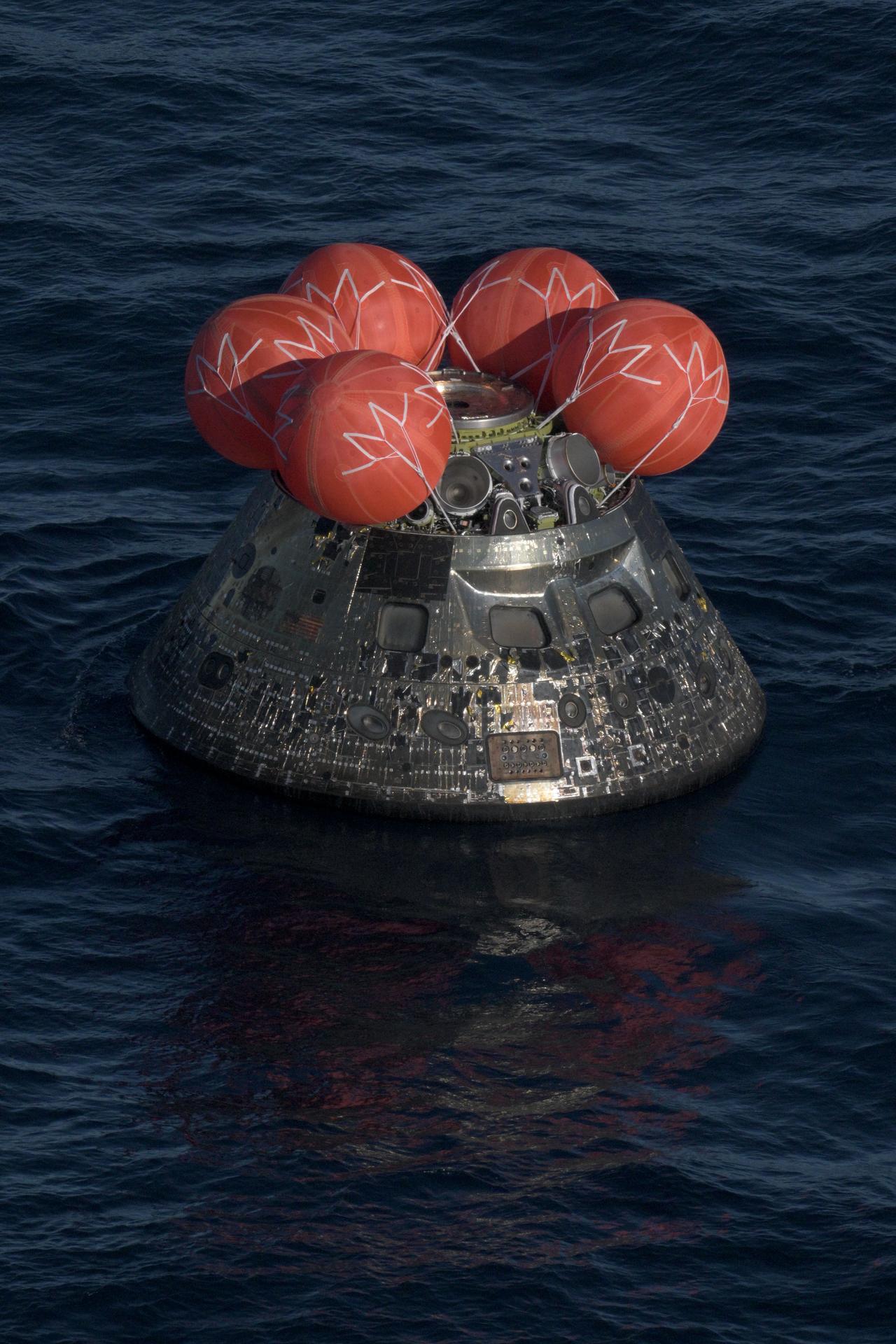
jsc2026e022266 (April 10, 2026) - NASA's Orion spacecraft carrying Artemis II Commander Reid Wiseman, Pilot Victor Glover, and Mission Specialist Christina Koch from NASA, along with Mission Specialist Jeremy Hansen from the CSA (Canadian Space Agency), splashes down in the Pacific Ocean near San Diego, California, at 5:07 p.m. PDT, (8:07 p.m. EDT) on Friday, April 10, 2026. The Artemis II test flight launched on Wednesday, April 1, from NASA’s Kennedy Space Center in Florida to begin its 10-day journey around the Moon for scientific discovery, economic benefits, and to build on our foundation for the first crewed missions to Mars. NASA’s Landing and Recovery team and the U.S. military are coordinating efforts to extract the Artemis II crew from the Orion spacecraft. Credit: NASA/James Blair
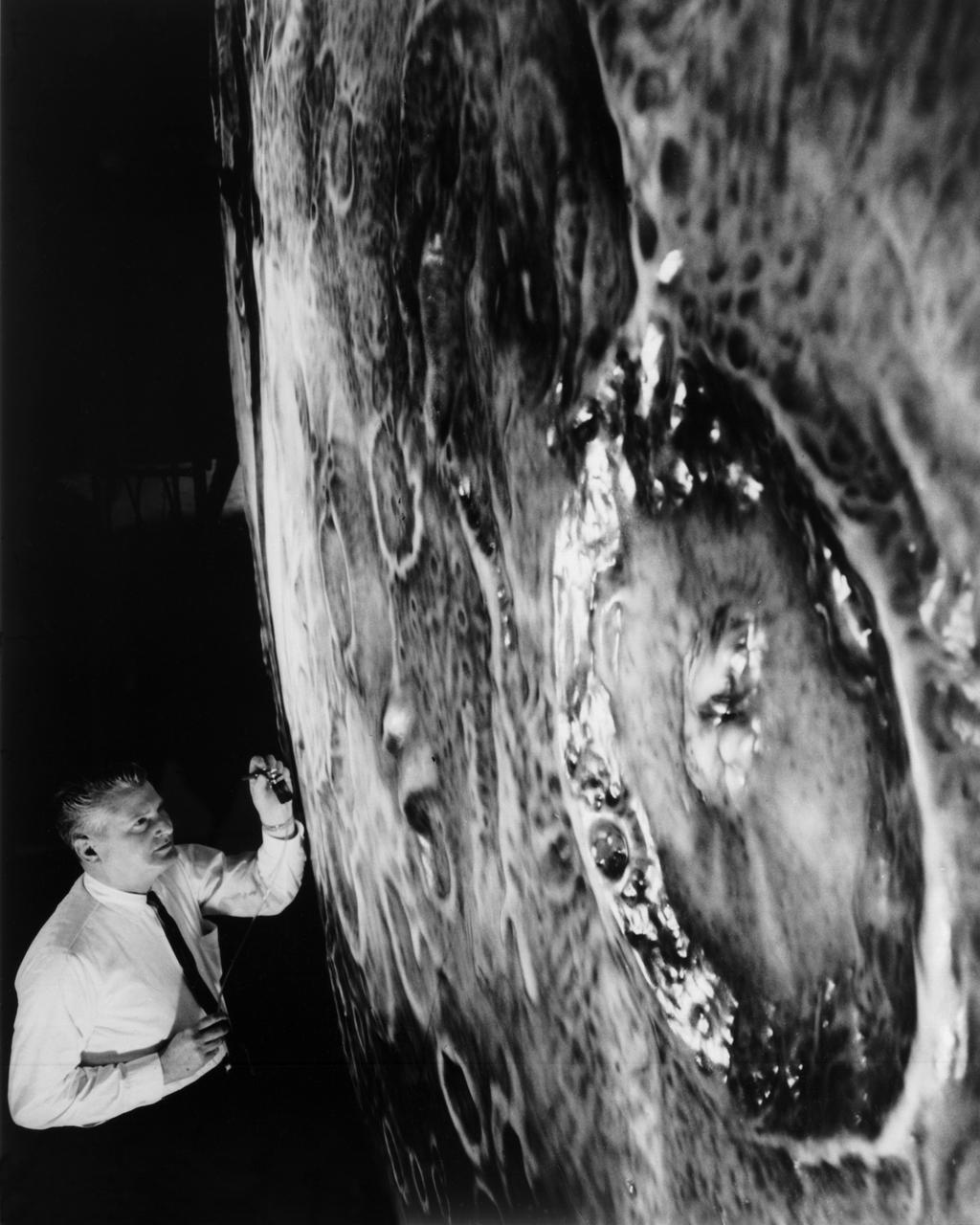
Artists used paintbrushes and airbrushes to recreate the lunar surface on each of the four models comprising the LOLA simulator. Project LOLA or Lunar Orbit and Landing Approach was a simulator built at Langley to study problems related to landing on the lunar surface. It was a complex project that cost nearly $2 million dollars. James Hansen wrote: "This simulator was designed to provide a pilot with a detailed visual encounter with the lunar surface; the machine consisted primarily of a cockpit, a closed-circuit TV system, and four large murals or scale models representing portions of the lunar surface as seen from various altitudes. The pilot in the cockpit moved along a track past these murals which would accustom him to the visual cues for controlling a spacecraft in the vicinity of the moon. Unfortunately, such a simulation--although great fun and quite aesthetic--was not helpful because flight in lunar orbit posed no special problems other than the rendezvous with the LEM, which the device did not simulate. Not long after the end of Apollo, the expensive machine was dismantled." (p. 379) Ellis J. White further described LOLA in his paper "Discussion of Three Typical Langley Research Center Simulation Programs," "Model 1 is a 20-foot-diameter sphere mounted on a rotating base and is scaled 1 in. = 9 miles. Models 2,3, and 4 are approximately 15x40 feet scaled sections of model 1. Model 4 is a scaled-up section of the Crater Alphonsus and the scale is 1 in. = 200 feet. All models are in full relief except the sphere." -- Published in James R. Hansen, Spaceflight Revolution: NASA Langley Research Center From Sputnik to Apollo, (Washington: NASA, 1995), p. 379; From Ellis J. White, "Discussion of Three Typical Langley Research Center Simulation Programs," Paper presented at the Eastern Simulation Council (EAI's Princeton Computation Center), Princeton, NJ, October 20, 1966.
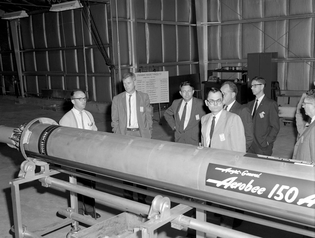
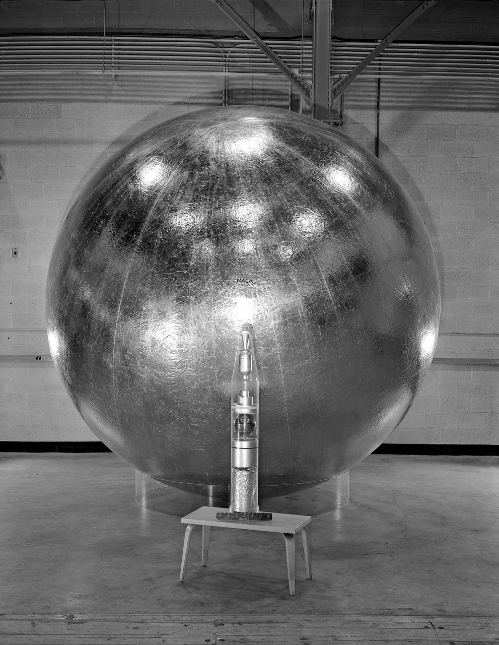
Photographed on 09/22/1960. -- An examination of the Aerojet-General "Aerobee 150A" propulsion system in February 1960. James Hansen described this as follows: "As for the technical definition of the rocket...the Langley engineers tried to keep developmental costs and time to a minimum by selecting components from off-the-shelf hardware. the majority of Scout's components were to come from an inventory of solid-fuel rockets produced for the military, although everyone involved understood that some improved motors would also have to be developed under contract. By early 1959, after intensive technical analysis and reviews, Langley settled on a design and finalized the selection of the major contractors. The rocket's 40-inch-diameter first stage was to be a new "Algol" motor, a combination of the Jupiter Senior and the navy Polaris produced by the Aerojet General Corporation, Sacramento, California. The 31-inch-diameter second stage, "Castor," was derived from the army's Sergeant and was to be manufactured by the Redstone Division of the Thiokol company in Huntsville, Alabama. the motor for the 30-inch-diameter third stage, "Antares," evolved under NASA contract from the ABL X248 design into a new version called the X254 (and subsequently into the X259); it was built under contract to NASA by ABL, a U.S. Navy Bureau of Ordnance facility operated by the Hercules Powder Company, Cumberland, Maryland. the final upper-stage propulsion unit, "Altair," which was 25.7 inches in diameter (34 inches at the heat shield), amounted to an improved edition of the X248 that was also manufactured by ABL." -- Published in James R. Hansen, Spaceflight Revolution: NASA Langley Research Center From Sputnik to Apollo, NASA SP-4308, pp.200-201.
Artists used paintbrushes and airbrushes to recreate the lunar surface on each of the four models comprising the LOLA simulator. Project LOLA or Lunar Orbit and Landing Approach was a simulator built at Langley to study problems related to landing on the lunar surface. It was a complex project that cost nearly 2 million dollars. James Hansen wrote: This simulator was designed to provide a pilot with a detailed visual encounter with the lunar surface the machine consisted primarily of a cockpit, a closed-circuit TV system, and four large murals or scale models representing portions of the lunar surface as seen from various altitudes. The pilot in the cockpit moved along a track past these murals which would accustom him to the visual cues for controlling a spacecraft in the vicinity of the moon. Unfortunately, such a simulation--although great fun and quite aesthetic--was not helpful because flight in lunar orbit posed no special problems other than the rendezvous with the LEM, which the device did not simulate. Not long after the end of Apollo, the expensive machine was dismantled. (p. 379) Ellis J. White described the simulator as follows: Model 1 is a 20-foot-diameter sphere mounted on a rotating base and is scaled 1 in. 9 miles. Models 2,3, and 4 are approximately 15x40 feet scaled sections of model 1. Model 4 is a scaled-up section of the Crater Alphonsus and the scale is 1 in. 200 feet. All models are in full relief except the sphere. -- Published in James R. Hansen, Spaceflight Revolution: NASA Langley Research Center From Sputnik to Apollo, (Washington: NASA, 1995), p. 379 Ellis J. White, Discussion of Three Typical Langley Research Center Simulation Programs, Paper presented at the Eastern Simulation Council (EAI s Princeton Computation Center), Princeton, NJ, October 20, 1966.
Artists used paintbrushes and airbrushes to recreate the lunar surface on each of the four models comprising the LOLA simulator. Project LOLA or Lunar Orbit and Landing Approach was a simulator built at Langley to study problems related to landing on the lunar surface. It was a complex project that cost nearly $2 million dollars. James Hansen wrote: "This simulator was designed to provide a pilot with a detailed visual encounter with the lunar surface; the machine consisted primarily of a cockpit, a closed-circuit TV system, and four large murals or scale models representing portions of the lunar surface as seen from various altitudes. The pilot in the cockpit moved along a track past these murals which would accustom him to the visual cues for controlling a spacecraft in the vicinity of the moon. Unfortunately, such a simulation--although great fun and quite aesthetic--was not helpful because flight in lunar orbit posed no special problems other than the rendezvous with the LEM, which the device did not simulate. Not long after the end of Apollo, the expensive machine was dismantled." (p. 379) Ellis J. White further described LOLA in his paper "Discussion of Three Typical Langley Research Center Simulation Programs," "Model 1 is a 20-foot-diameter sphere mounted on a rotating base and is scaled 1 in. = 9 miles. Models 2,3, and 4 are approximately 15x40 feet scaled sections of model 1. Model 4 is a scaled-up section of the Crater Alphonsus and the scale is 1 in. = 200 feet. All models are in full relief except the sphere." -- Published in James R. Hansen, Spaceflight Revolution: NASA Langley Research Center From Sputnik to Apollo, (Washington: NASA, 1995), p. 379; Ellis J. White, "Discussion of Three Typical Langley Research Center Simulation Programs," Paper presented at the Eastern Simulation Council (EAI's Princeton Computation Center), Princeton, NJ, October 20, 1966.
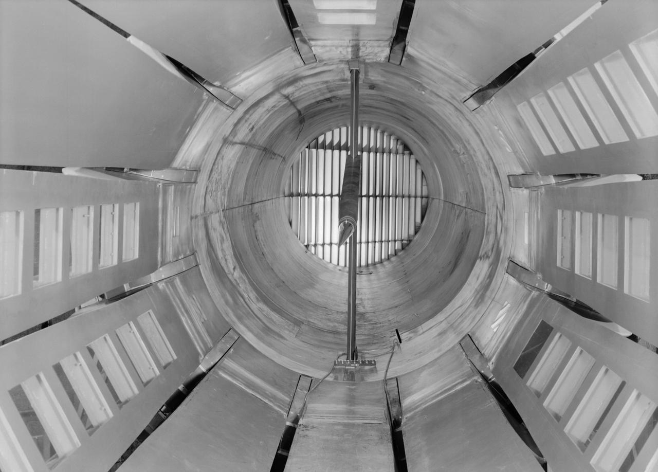
Interior view of the slotted throat test section installed in the 8-Foot High Speed Tunnel (HST) in 1950. The slotted region is about 160 inches in length. In this photograph, the sting-type model support is seen straight on. In a NASA report, the test section is described as follows: The test section of the Langley 8-foot transonic tunnel is dodecagonal in cross section and has a cross-sectional area of about 43 square feet. Longitudinal slots are located between each of the 12 wall panels to allow continuous operation through the transonic speed range. The slots contain about 11 percent of the total periphery of the test section. Six of the twelve panels have windows in them to allow for schlieren observations. The entire test section is enclosed in a hemispherical shaped chamber. John Becker noted that the tunnel s final achievement was the development and use in routine operations of the first transonic slotted throat. The investigations of wing-body shapes in this tunnel led to Whitcomb s discovery of the transonic area rule. James Hansen described the origins of the the slotted throat as follows: In 1946 Langley physicist Ray H. Wright conceived a way to do transonic research effectively in a wind tunnel by placing slots in the throat of the test section. The concept for what became known as the slotted-throat or slotted-wall tunnel came to Wright not as a solution to the chronic transonic problem, but as a way to get rid of wall interference (i.e., the mutual effect of two or more meeting waves or vibrations of any kind caused by solid boundaries) at subsonic speeds. For most of the year before Wright came up with this idea, he had been trying to develop a theoretical understanding of wall interference in the 8-Foot HST, which was then being repowered for Mach 1 capability. When Wright presented these ideas to John Stack, the response was enthusiastic but neither Wright nor Stack thought of slotted-throats as a solution to the transonic problem, only the wall interference problem. It was an accidental discovery which showed that slotted throats might solve the transonic problem. Most engineers were skeptical but Stack persisted. Initially, plans were to modify the 16-Foot tunnel but in the spring of 1948, Stack announced that the 8-Foot HST would also be modified. As Hansen notes: The 8-Foot HST began regular transonic operations for research purposes on 6 October 1950. The concept was a success and led to plans for a new wind tunnel which would be known as the 8-Foot Transonic Pressure Tunnel. -- Published in U.S., National Advisory Committee for Aeronautics, Characteristics of Nine Research Wind Tunnels of the Langley Aeronautical Laboratory, 1957, pp. 17, 22 James R. Hansen, Engineer in Charge, NASA SP-4305, p. 454 and Chapter 11, The Slotted Tunnel and the Area Rule.
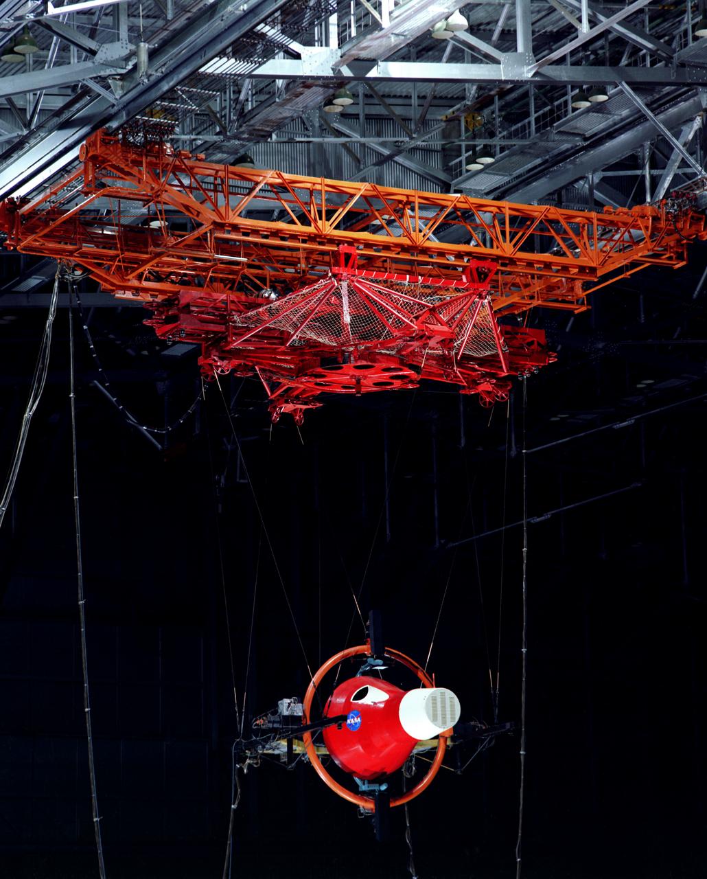
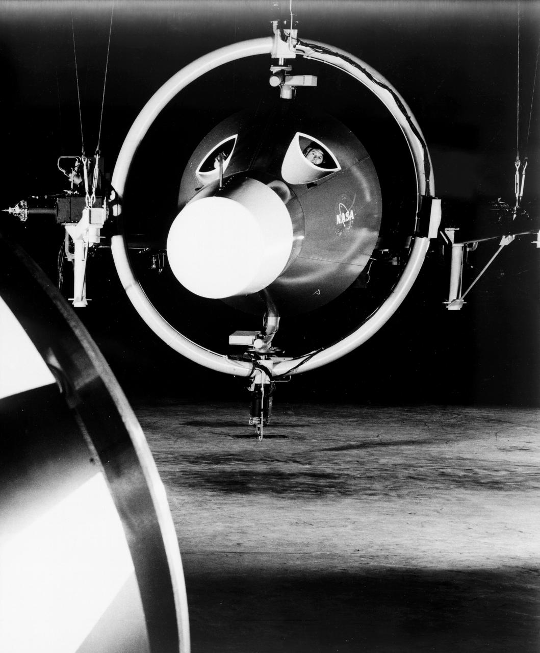
Gemini Rendezvous Docking Simulator suspended from the roof of the Langley Research Center s aircraft hangar. Francis B. Smith wrote: The rendezvous and docking operation of the Gemini spacecraft with the Agena and of the Apollo Command Module with the Lunar Excursion Module have been the subject of simulator studies for several years. This figure illustrates the Gemini-Agena rendezvous docking simulator at Langley. The Gemini spacecraft was supported in a gimbal system by an overhead crane and gantry arrangement which provided 6 degrees of freedom - roll, pitch, yaw, and translation in any direction - all controllable by the astronaut in the spacecraft. Here again the controls fed into a computer which in turn provided an input to the servos driving the spacecraft so that it responded to control motions in a manner which accurately simulated the Gemini spacecraft. -- Published in Barton C. Hacker and James M. Grimwood, On the Shoulders of Titans: A History of Project Gemini, NASA SP-4203 Francis B. Smith, Simulators for Manned Space Research, Paper presented at the 1966 IEEE International convention, March 21-25, 1966.

Project LOLA. Test subject sitting at the controls: Project LOLA or Lunar Orbit and Landing Approach was a simulator built at Langley to study problems related to landing on the lunar surface. It was a complex project that cost nearly 2 million dollars. James Hansen wrote: This simulator was designed to provide a pilot with a detailed visual encounter with the lunar surface the machine consisted primarily of a cockpit, a closed-circuit TV system, and four large murals or scale models representing portions of the lunar surface as seen from various altitudes. The pilot in the cockpit moved along a track past these murals which would accustom him to the visual cues for controlling a spacecraft in the vicinity of the moon. Unfortunately, such a simulation--although great fun and quite aesthetic--was not helpful because flight in lunar orbit posed no special problems other than the rendezvous with the LEM, which the device did not simulate. Not long after the end of Apollo, the expensive machine was dismantled. (p. 379) Ellis J. White wrote in his paper, Discussion of Three Typical Langley Research Center Simulation Programs : A typical mission would start with the first cart positioned on model 1 for the translunar approach and orbit establishment. After starting the descent, the second cart is readied on model 2 and, at the proper time, when superposition occurs, the pilot s scene is switched from model 1 to model 2. then cart 1 is moved to and readied on model 3. The procedure continues until an altitude of 150 feet is obtained. The cabin of the LM vehicle has four windows which represent a 45 degree field of view. The projection screens in front of each window represent 65 degrees which allows limited head motion before the edges of the display can be seen. The lunar scene is presented to the pilot by rear projection on the screens with four Schmidt television projectors. The attitude orientation of the vehicle is represented by changing the lunar scene through the portholes determined by the scan pattern of four orthicons. The stars are front projected onto the upper three screens with a four-axis starfield generation (starball) mounted over the cabin and there is a separate starball for the low window. -- Published in James R. Hansen, Spaceflight Revolution: NASA Langley Research Center From Sputnik to Apollo, (Washington: NASA, 1995), p. 379 Ellis J. White, Discussion of Three Typical Langley Research Center Simulation Programs, Paper presented at the Eastern Simulation Council (EAI s Princeton Computation Center), Princeton, NJ, October 20, 1966.
Test subject sitting at the controls: Project LOLA or Lunar Orbit and Landing Approach was a simulator built at Langley to study problems related to landing on the lunar surface. It was a complex project that cost nearly $2 million dollars. James Hansen wrote: "This simulator was designed to provide a pilot with a detailed visual encounter with the lunar surface; the machine consisted primarily of a cockpit, a closed-circuit TV system, and four large murals or scale models representing portions of the lunar surface as seen from various altitudes. The pilot in the cockpit moved along a track past these murals which would accustom him to the visual cues for controlling a spacecraft in the vicinity of the moon. Unfortunately, such a simulation--although great fun and quite aesthetic--was not helpful because flight in lunar orbit posed no special problems other than the rendezvous with the LEM, which the device did not simulate. Not long after the end of Apollo, the expensive machine was dismantled." (p. 379) Ellis J. White further described this simulator in his paper , "Discussion of Three Typical Langley Research Center Simulation Programs," (Paper presented at the Eastern Simulation Council (EAI's Princeton Computation Center), Princeton, NJ, October 20, 1966.) "A typical mission would start with the first cart positioned on model 1 for the translunar approach and orbit establishment. After starting the descent, the second cart is readied on model 2 and, at the proper time, when superposition occurs, the pilot's scene is switched from model 1 to model 2. then cart 1 is moved to and readied on model 3. The procedure continues until an altitude of 150 feet is obtained. The cabin of the LM vehicle has four windows which represent a 45 degree field of view. The projection screens in front of each window represent 65 degrees which allows limited head motion before the edges of the display can be seen. The lunar scene is presented to the pilot by rear projection on the screens with four Schmidt television projectors. The attitude orientation of the vehicle is represented by changing the lunar scene through the portholes determined by the scan pattern of four orthicons. The stars are front projected onto the upper three screens with a four-axis starfield generation (starball) mounted over the cabin and there is a separate starball for the low window." -- Published in James R. Hansen, Spaceflight Revolution: NASA Langley Research Center From Sputnik to Apollo, (Washington: NASA, 1995), p. 379.
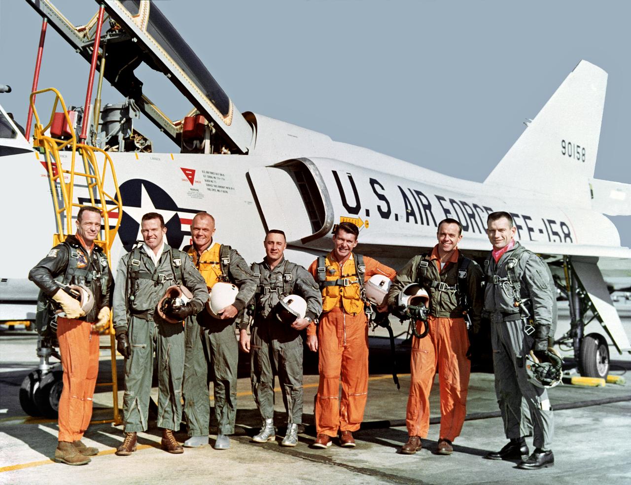
The original seven Mercury astronauts during training at NASA Langley Research Center Project Mercury. The original seven astronauts trained at NASA Langley Research Center. Chosen from among hundreds of applicants, the seven men were all test pilots. Standing in front of the U.S. Air Force Convair F-106B aircraft, the astronauts are, from left, Lt. M. Scott Carpenter, Capt. Gordon Cooper, Col. John H. Glenn Jr., Capt. Virgil "Gus" Grissom, Lt. Comdr. Walter Schirra, Lt. Comdr. Alan B. Shepard Jr. and Capt. Donald K. "Deke" Slayton. While familiarizing the astronauts with the Mercury set-up, Langley employees helped them to specialize in the technical areas crucial to the overall success of Project Mercury. Langley people also guided and monitored the astronauts activities through the many spaceflight simulators and other training devices built at the Center expressly for the manned space program. In less than three years, Project Mercury proved that men could be sent into space and returned safely to Earth, setting the stage for the longer duration Gemini flights and the Apollo lunar landings. This photograph was originally taken on 01/20/1961 and is published in Spaceflight Revolution NASA Langley Research Center from Sputnik to Apollo, NASA SP-4308, by James R. Hansen, 1995, page 40.
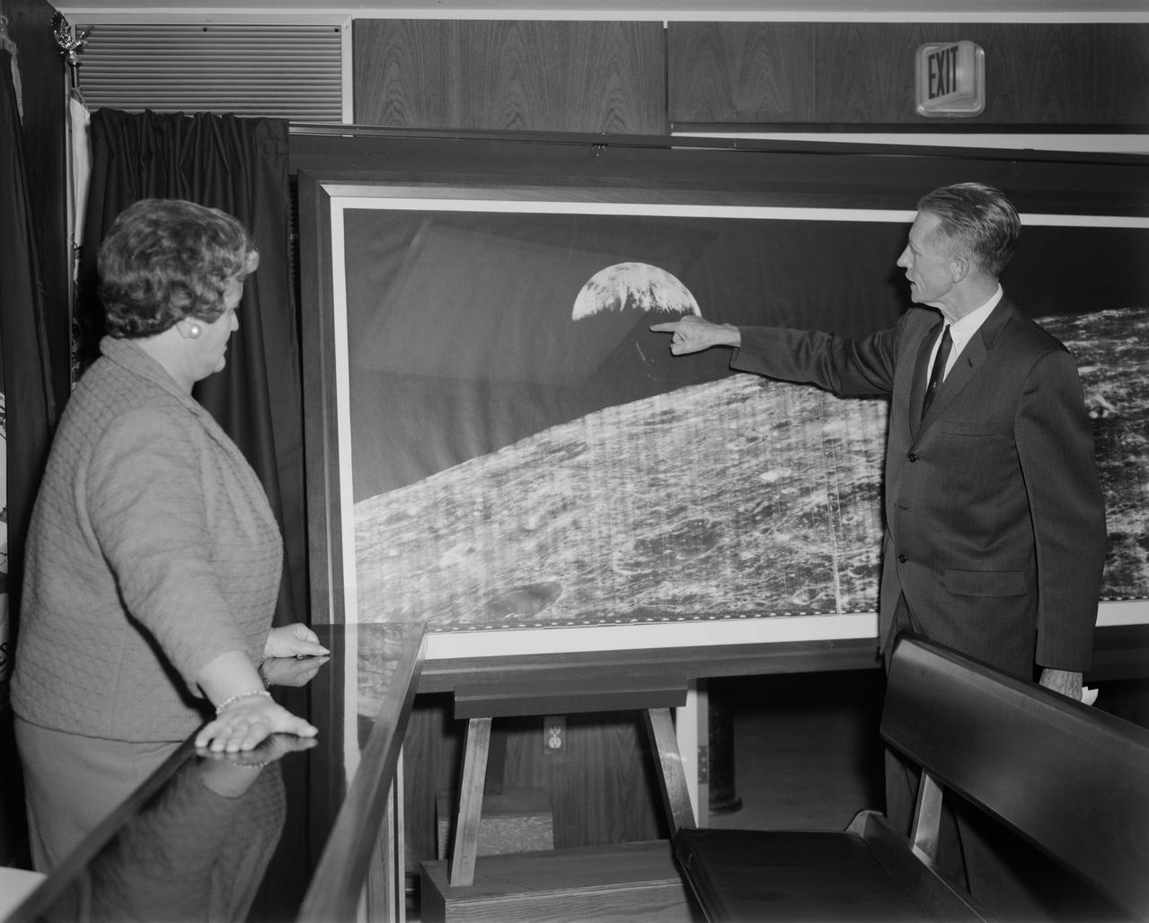
Langley Center Director Floyd Thompson shows Ann Kilgore the "picture of the century." This was the first picture of the earth taken from space. From Spaceflight Revolution: "On 23 August 1966 just as Lunar Orbiter I was about to pass behind the moon, mission controllers executed the necessary maneuvers to point the camera away from the lunar surface and toward the earth. The result was the world's first view of the earth from space. It was called "the picture of the century' and "the greatest shot taken since the invention of photography." Not even the color photos of the earth taken during the Apollo missions superseded the impact of this first image of our planet as a little island of life floating in the black and infinite sea of space." -- Published in James R. Hansen, Spaceflight Revolution: NASA Langley Research Center From Sputnik to Apollo, (Washington: NASA, 1995), pp. 345-346. Mayor Ann Kilgore was married to NASA researcher Edwin Carroll Kilgore. Mrs. Kilgore was Mayor from 1963-1971 and again from 1974-1978.
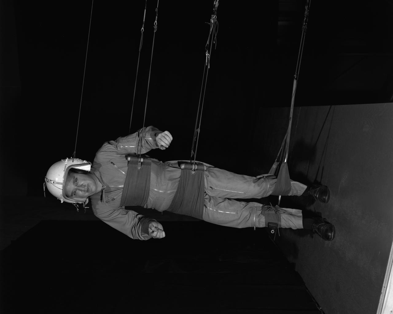
Reduced Gravity Walking Simulator located in the hangar at Langley Research Center. The initial version of this simulator was located inside the hangar. Later a larger version would be located at the Lunar Landing Facility. The purpose of this simulator was to study the subject while walking, jumping or running. Researchers conducted studies of various factors such as fatigue limit, energy expenditure, and speed of locomotion. A.W. Vigil wrote in his paper Discussion of Existing and Planned Simulators for Space Research, When the astronauts land on the moon they will be in an unfamiliar environment involving, particularly, a gravitational field only one-sixth as strong as on earth. A novel method of simulating lunar gravity has been developed and is supported by a puppet-type suspension system at the end of a long pendulum. A floor is provided at the proper angle so that one-sixth of the subject' s weight is supported by the floor with the remainder being supported by the suspension system. This simulator allows almost complete freedom in vertical translation and pitch and is considered to be a very realistic simulation of the lunar walking problem. For this problem this simulator suffers only slightly from the restrictions in lateral movement it puts on the test subject. This is not considered a strong disadvantage for ordinary walking problems since most of the motions do, in fact, occur in the vertical plane. However, this simulation technique would be severely restrictive if applied to the study of the extra-vehicular locomotion problem, for example, because in this situation complete six degrees of freedom are rather necessary. This technique, in effect, automatically introduces a two-axis attitude stabilization system into the problem. The technique could, however, be used in preliminary studies of extra-vehicular locomotion where, for example, it might be assumed that one axis of the attitude control system on the astronaut maneuvering unit may have failed. -- Published in James R. Hansen, Spaceflight Revolution: NASA Langley Research Center From Sputnik to Apollo, NASA SP-4308, p. 377 A.W. Vigil, Discussion of Existing and Planned Simulators for Space Research, Paper presented at Conference on the Role of Simulation in Space Technology, Blacksburg, VA, August 17-21, 1964.
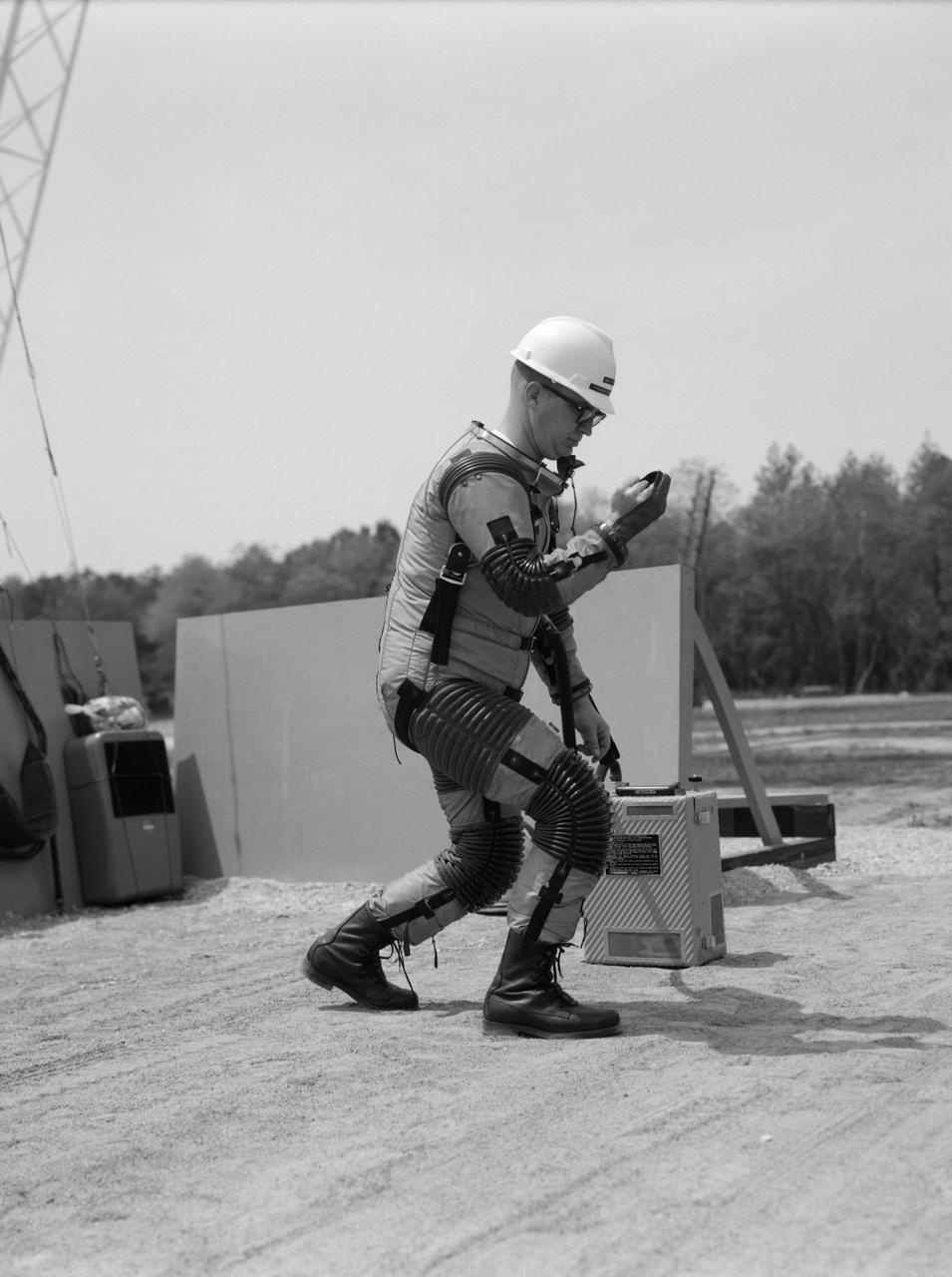
Special "space" suit for the Reduced Gravity Walking Simulator located at the Lunar Landing Facility. The purpose of this simulator was to study the subject while walking, jumping or running. Researchers conducted studies of various factors such as fatigue limit, energy expenditure, and speed of locomotion. A.W. Vigil described the purpose of the simulator in his paper "Discussion of Existing and Planned Simulators for Space Research," "When the astronauts land on the moon they will be in an unfamiliar environment involving, particularly, a gravitational field only one-sixth as strong as on earth. A novel method of simulating lunar gravity has been developed and is supported by a puppet-type suspension system at the end of a long pendulum. A floor is provided at the proper angle so that one-sixth of the subject's weight is supported by the floor with the remainder being supported by the suspension system. This simulator allows almost complete freedom in vertical translation and pitch and is considered to be a very realistic simulation of the lunar walking problem. For this problem this simulator suffers only slightly from the restrictions in lateral movement it puts on the test subject. This is not considered a strong disadvantage for ordinary walking problems since most of the motions do, in fact, occur in the vertical plane. However, this simulation technique would be severely restrictive if applied to the study of the extra-vehicular locomotion problem, for example, because in this situation complete six degrees of freedom are rather necessary. This technique, in effect, automatically introduces a two-axis attitude stabilization system into the problem. The technique could, however, be used in preliminary studies of extra-vehicular locomotion where, for example, it might be assumed that one axis of the attitude control system on the astronaut maneuvering unit may have failed." -- Published in James R. Hansen, Spaceflight Revolution: NASA Langley Research Center From Sputnik to Apollo, (Washington: NASA, 1995), p. 377; A.W. Vigil, "Discussion of Existing and Planned Simulators for Space Research," Paper presented at Conference on the Role of Simulation in Space Technology," Blacksburg, VA, August 17-21, 1964.
Test subject wearing the pressurized "space" suit for the Reduced Gravity Walking Simulator located at the Lunar Landing Facility. The purpose of this simulator was to study the subject while walking, jumping or running. Researchers conducted studies of various factors such as fatigue limit, energy expenditure, and speed of locomotion. A.W. Vigil described the purpose of the simulator in his paper "Discussion of Existing and Planned Simulators for Space Research," "When the astronauts land on the moon they will be in an unfamiliar environment involving, particularly, a gravitational field only one-sixth as strong as on earth. A novel method of simulating lunar gravity has been developed and is supported by a puppet-type suspension system at the end of a long pendulum. A floor is provided at the proper angle so that one-sixth of the subject's weight is supported by the floor with the remainder being supported by the suspension system. This simulator allows almost complete freedom in vertical translation and pitch and is considered to be a very realistic simulation of the lunar walking problem. For this problem this simulator suffers only slightly from the restrictions in lateral movement it puts on the test subject. This is not considered a strong disadvantage for ordinary walking problems since most of the motions do, in fact, occur in the vertical plane. However, this simulation technique would be severely restrictive if applied to the study of the extra-vehicular locomotion problem, for example, because in this situation complete six degrees of freedom are rather necessary. This technique, in effect, automatically introduces a two-axis attitude stabilization system into the problem. The technique could, however, be used in preliminary studies of extra-vehicular locomotion where, for example, it might be assumed that one axis of the attitude control system on the astronaut maneuvering unit may have failed." -- Published in James R. Hansen, Spaceflight Revolution: NASA Langley Research Center From Sputnik to Apollo, (Washington: NASA, 1995), p. 377; A.W. Vigil, "Discussion of Existing and Planned Simulators for Space Research," Paper presented at Conference on the Role of Simulation in Space Technology," Blacksburg, VA, August 17-21, 1964.
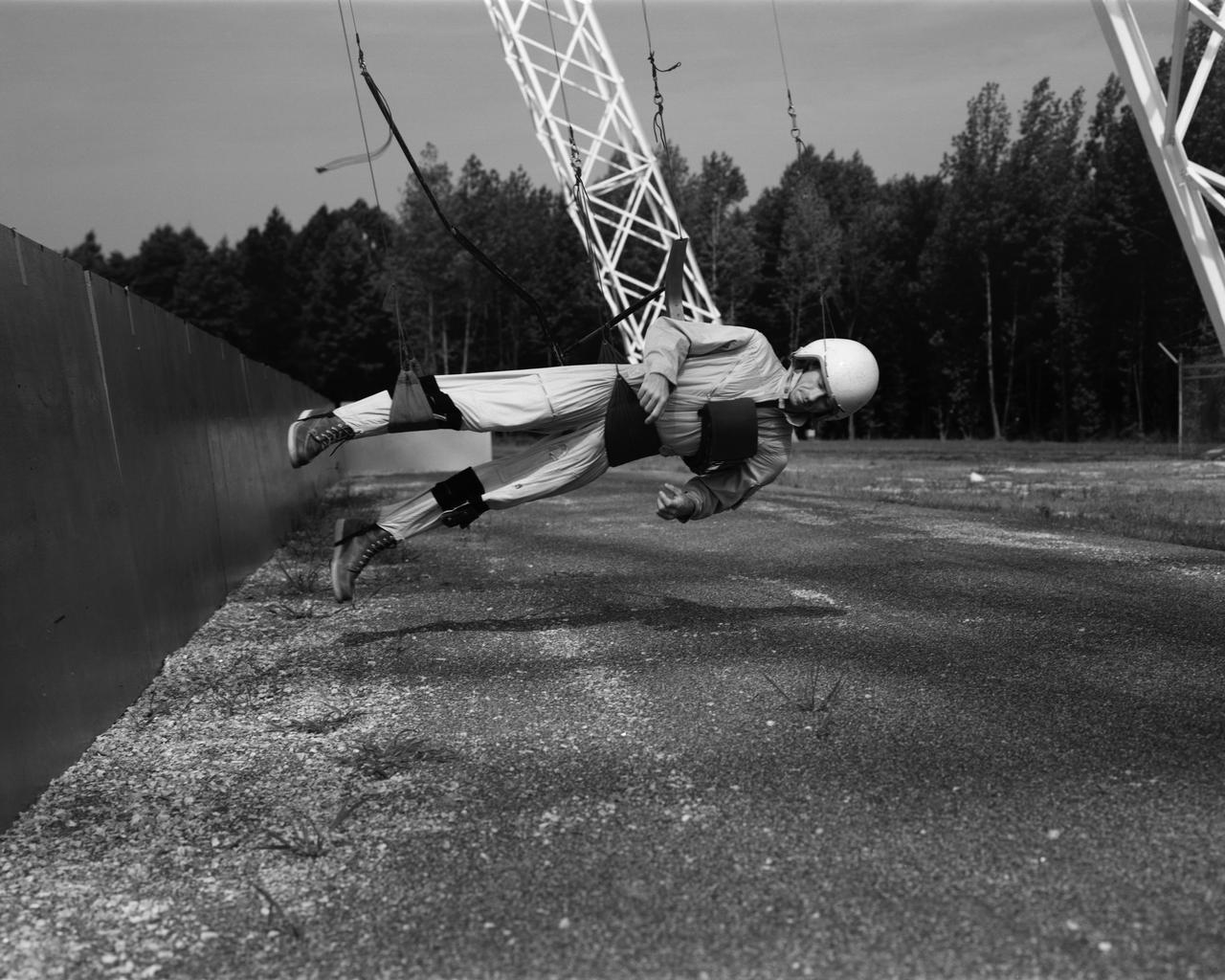
Astronaut Walt Cunningham on the Reduced Gravity Walking Simulator located at the Lunar Landing Facility. The purpose of this simulator was to study the subject while walking, jumping or running. Researchers conducted studies of various factors such as fatigue limit, energy expenditure, and speed of locomotion. A.W. Vigil described the purpose of the simulator in his paper "Discussion of Existing and Planned Simulators for Space Research," "When the astronauts land on the moon they will be in an unfamiliar environment involving, particularly, a gravitational field only one-sixth as strong as on earth. A novel method of simulating lunar gravity has been developed and is supported by a puppet-type suspension system at the end of a long pendulum. A floor is provided at the proper angle so that one-sixth of the subject's weight is supported by the floor with the remainder being supported by the suspension system. This simulator allows almost complete freedom in vertical translation and pitch and is considered to be a very realistic simulation of the lunar walking problem. For this problem this simulator suffers only slightly from the restrictions in lateral movement it puts on the test subject. This is not considered a strong disadvantage for ordinary walking problems since most of the motions do, in fact, occur in the vertical plane. However, this simulation technique would be severely restrictive if applied to the study of the extra-vehicular locomotion problem, for example, because in this situation complete six degrees of freedom are rather necessary. This technique, in effect, automatically introduces a two-axis attitude stabilization system into the problem. The technique could, however, be used in preliminary studies of extra-vehicular locomotion where, for example, it might be assumed that one axis of the attitude control system on the astronaut maneuvering unit may have failed." -- Published in James R. Hansen, Spaceflight Revolution: NASA Langley Research Center From Sputnik to Apollo, (Washington: NASA, 1995), p. 377; A.W. Vigil, "Discussion of Existing and Planned Simulators for Space Research," Paper presented at Conference on the Role of Simulation in Space Technology," Blacksburg, VA, August 17-21, 1964.