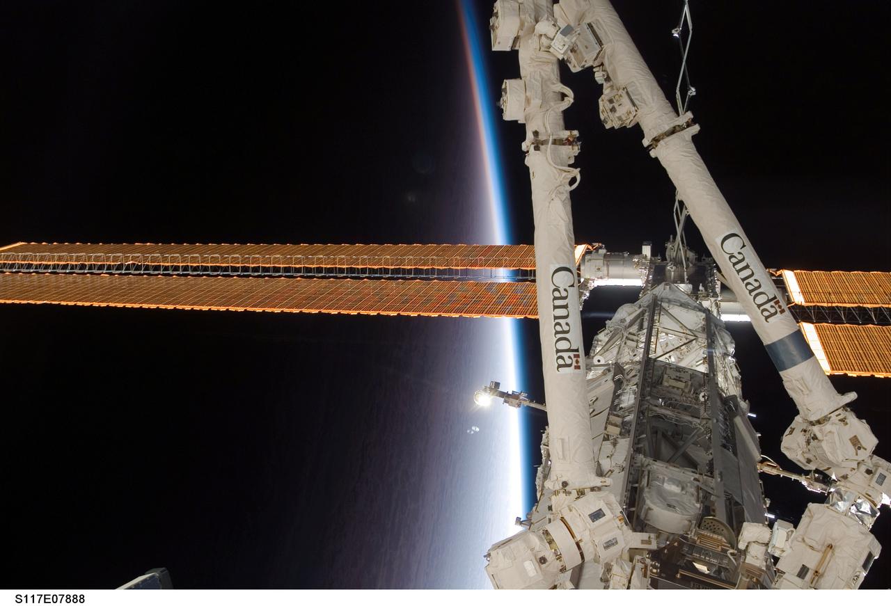
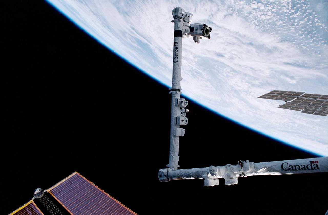
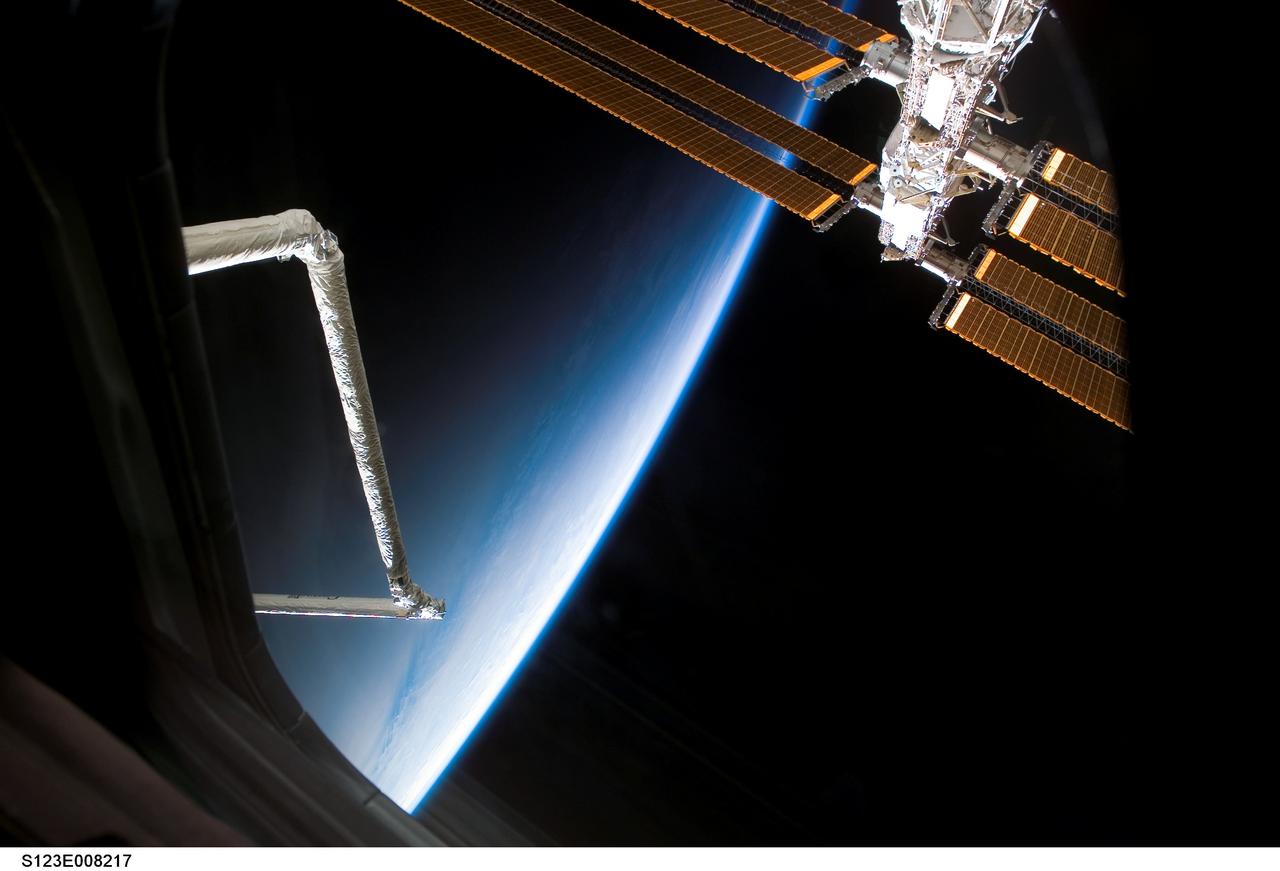
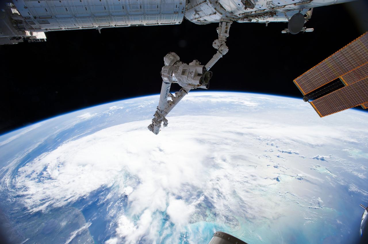
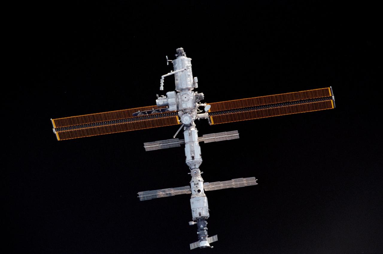
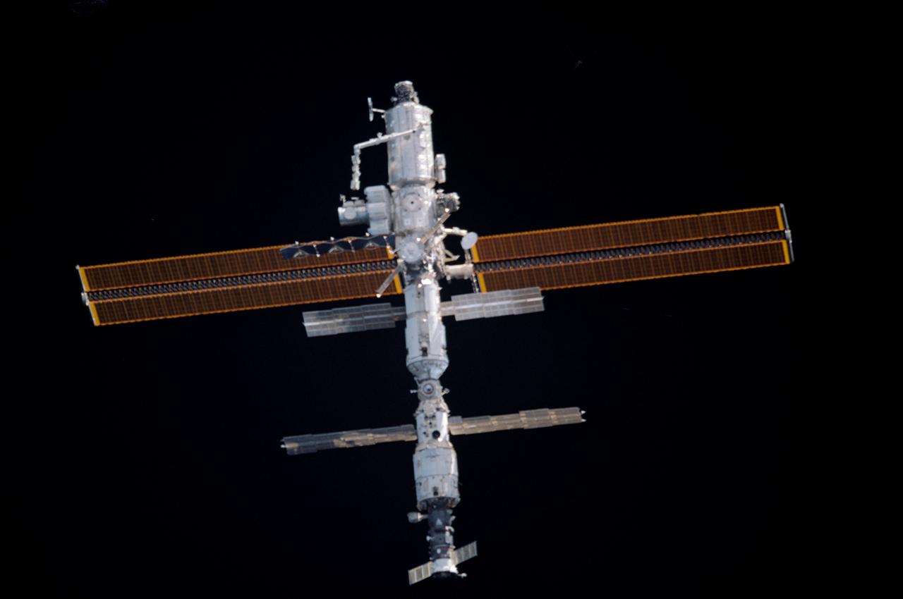
Overall nadir view of ISS seen during flyaround STS104-332-027 (21 July 2001) --- The International Space Station (ISS), just days after receiving the installment of the Quest airlock, was photographed by one the STS-104 astronauts during a fly-around of the orbital outpost. The survey occurred shortly after Atlantis' undocking. The Canadarm2 or Space Station Remote Manipulator System (SSRMS) appears to be pointed toward the new airlock on the station's starboard side. The STS-104 and Expedition Two crew's joint efforts in the past several days, in which the airlock was installed and other work was accomplished, marked the completion of the second phase of the station. Within the last year (beginning in July of 2000), 77 tons of hardware have been added to the complex, including the Zvezda module, the Z1 Truss Assembly, Pressurized Mating Adapter 3, the P6 Truss and its 240-foot long solar arrays, the U.S. laboratory Destiny, the Canadarm2 and finally the Quest airlock.