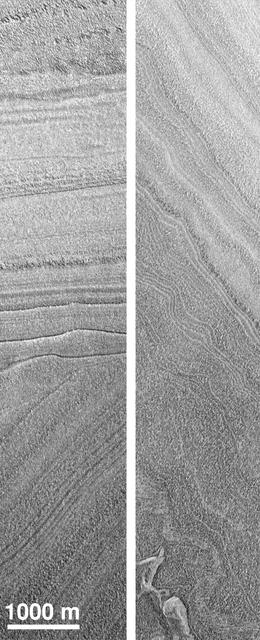
Polar Structures

Structure in the Spiral
A Hint of Structure
Structure in the Shadows
ERA COLTS 30 Toot Checkout Structure Installation: Document relocation of COLTS loading platen 30 Foot Station and installation of 30 Foot Checkout Structure
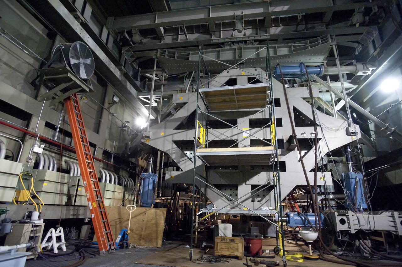
ERA COLTS 30 Toot Checkout Structure Installation: Document relocation of COLTS loading platen 30 Foot Station and installation of 30 Foot Checkout Structure
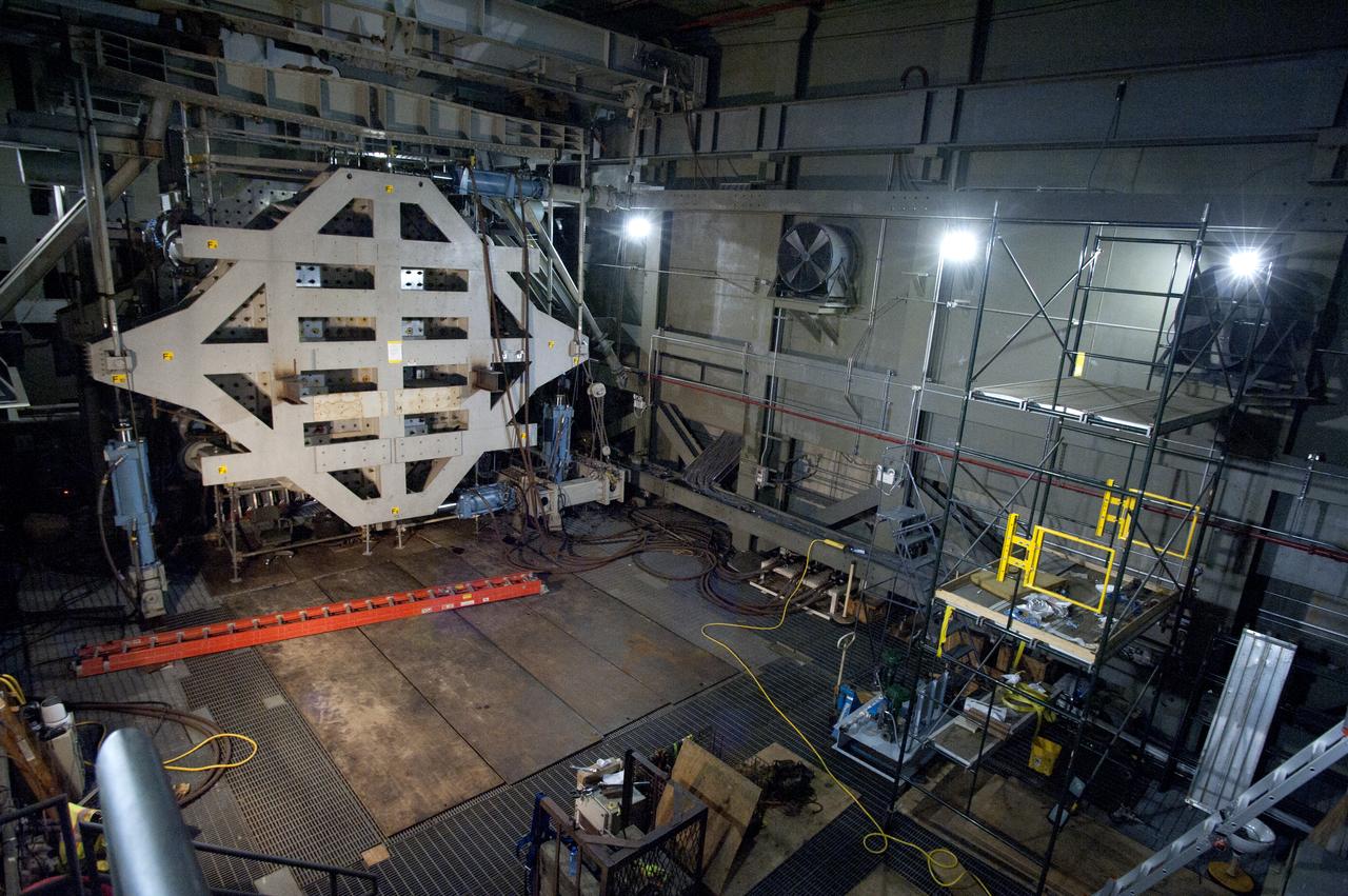
ERA COLTS 30 Toot Checkout Structure Installation: Document relocation of COLTS loading platen 30 Foot Station and installation of 30 Foot Checkout Structure

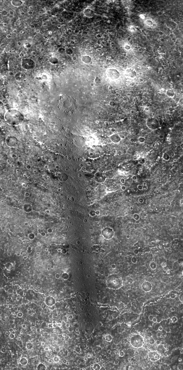
Image taken 1/11/2001: The so-called Richat Structure is a geological formation in the Maur Adrar Desert in the African country of Mauritania. Although it resembles an impact crater, the Richat Structure formed when a volcanic dome hardened and gradually eroded, exposing the onion-like layers of rock. The Richat Structure can be found on Landsat 7 WRS Path 203 Row 45, center: 21.68, -11.94. To learn more about the Landsat satellite go to: <a href="http://landsat.gsfc.nasa.gov/" rel="nofollow">landsat.gsfc.nasa.gov/</a> Credit: NASA/GSFC/Landsat 7/USGS
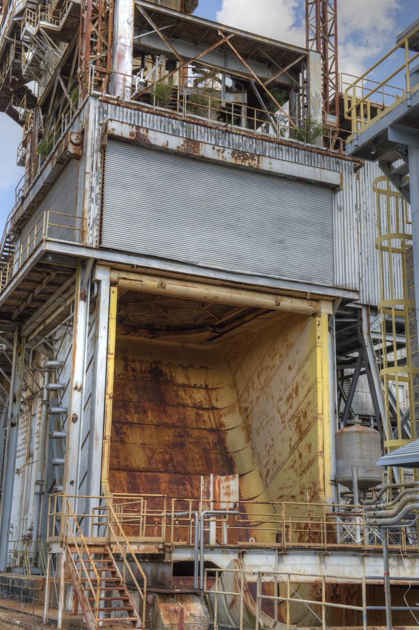
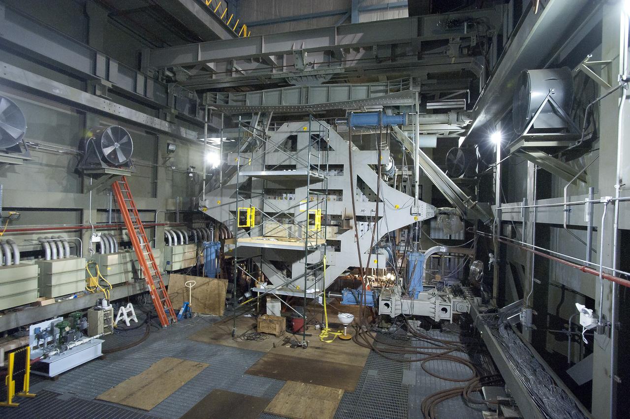
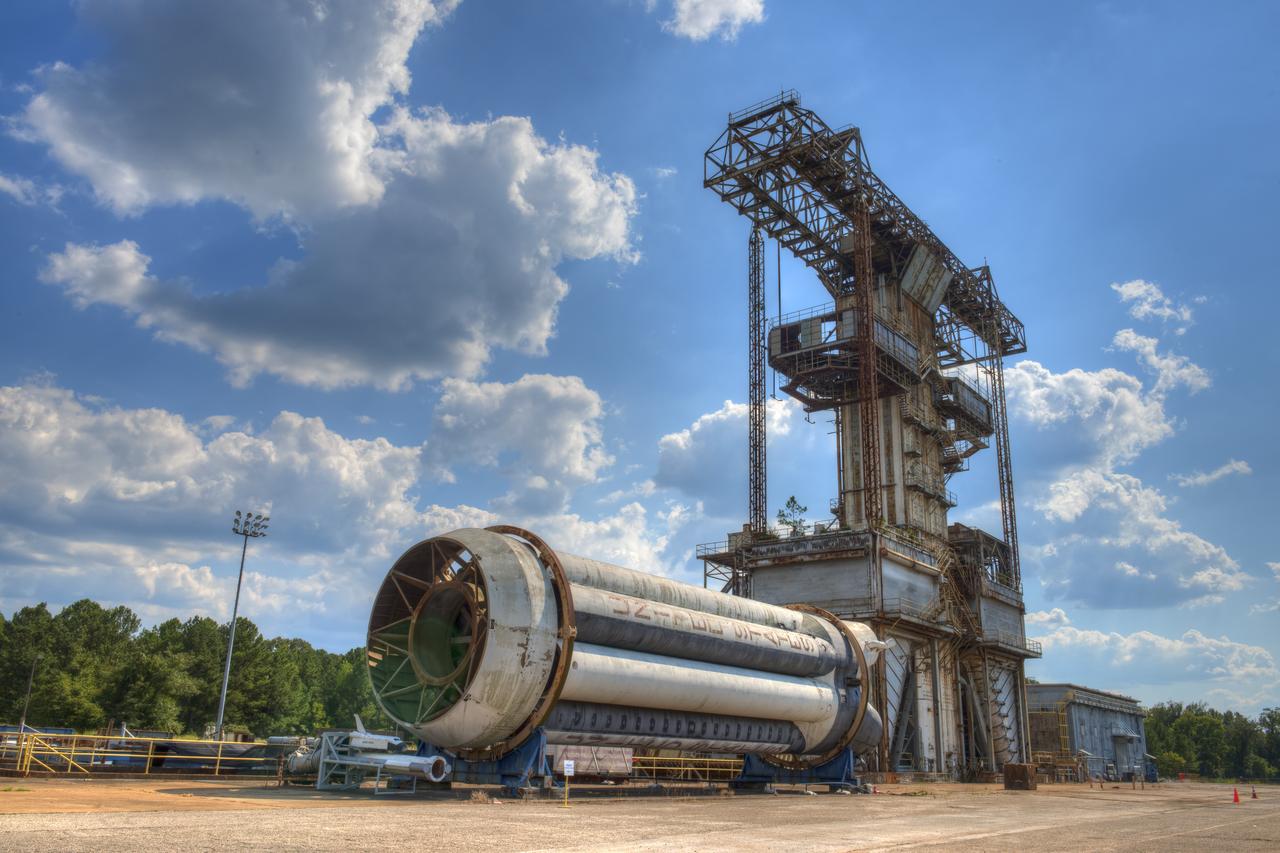
PROPULSION AND STRUCTURAL TEST FACILITY (BUILDING 4572) AT THE GEORGE C. MARSHALL SPACE FLIGHT CENTER IN HUNTSVILLE, ALABAMA
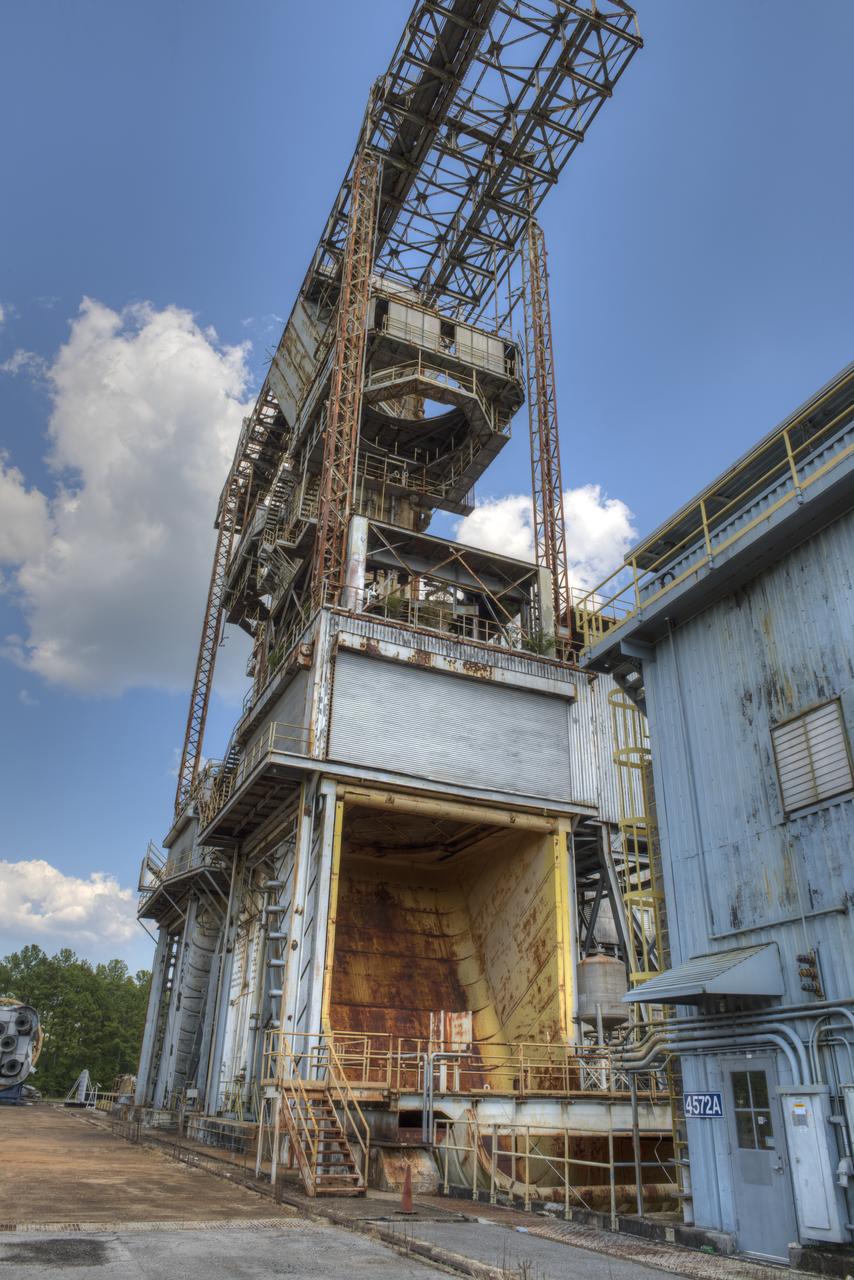
PROPULSION AND STRUCTURAL TEST FACILITY (BUILDING 4572) AT THE GEORGE C. MARSHALL SPACE FLIGHT CENTER IN HUNTSVILLE, ALABAMA
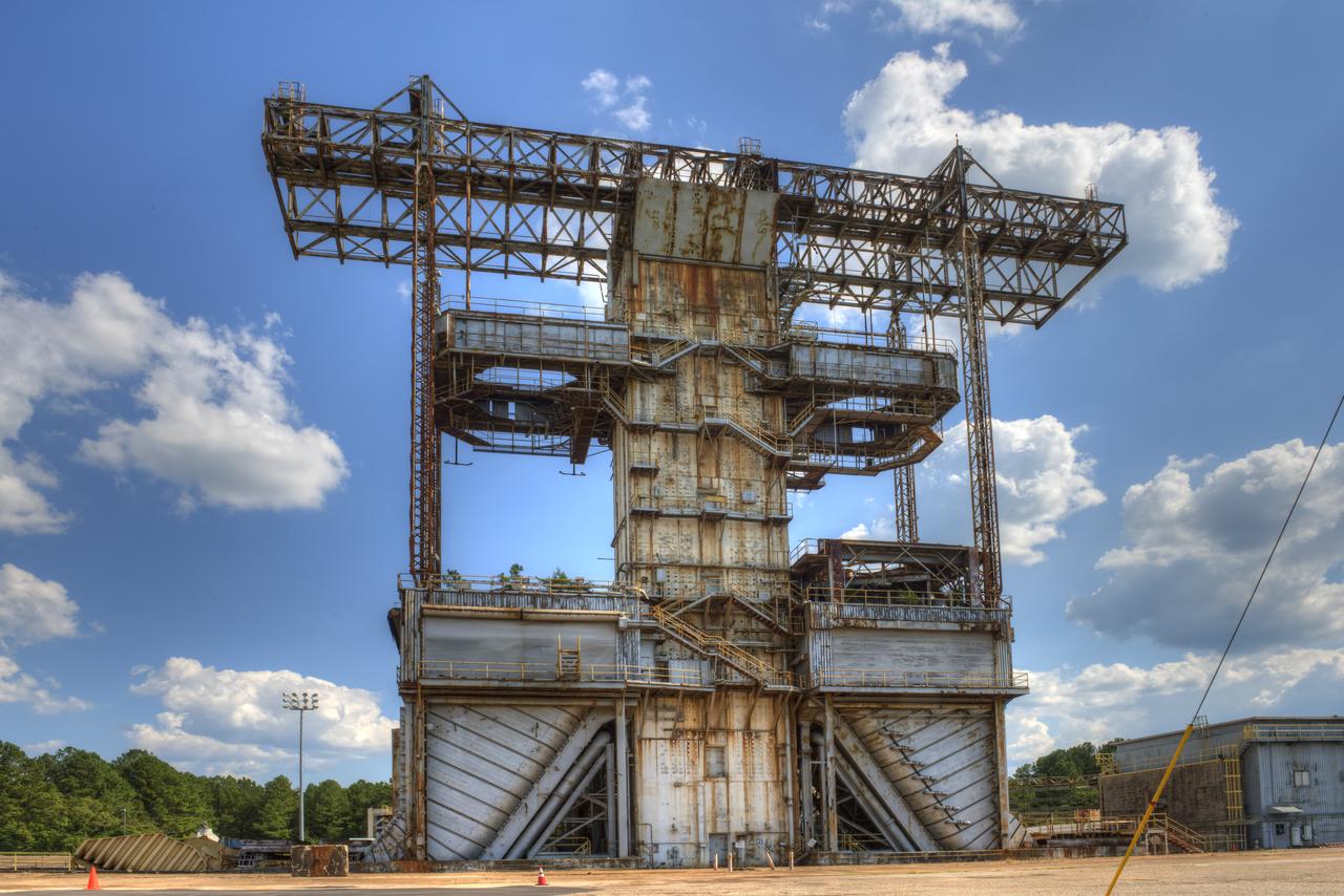
PROPULSION AND STRUCTURAL TEST FACILITY (BUILDING 4572) AT THE GEORGE C. MARSHALL SPACE FLIGHT CENTER IN HUNTSVILLE, ALABAMA
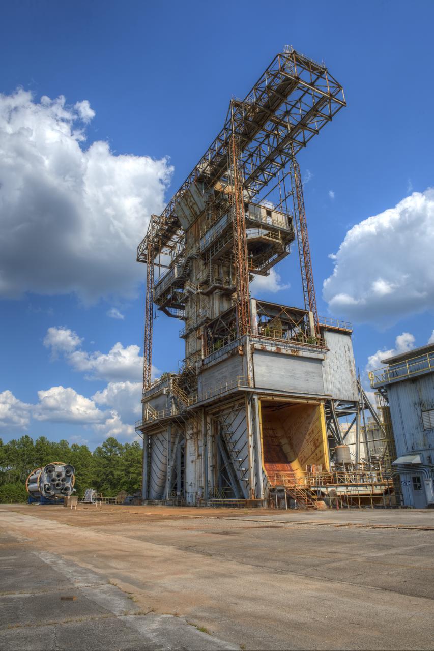
PROPULSION AND STRUCTURAL TEST FACILITY (BUILDING 4572) AT THE GEORGE C. MARSHALL SPACE FLIGHT CENTER IN HUNTSVILLE, ALABAMA
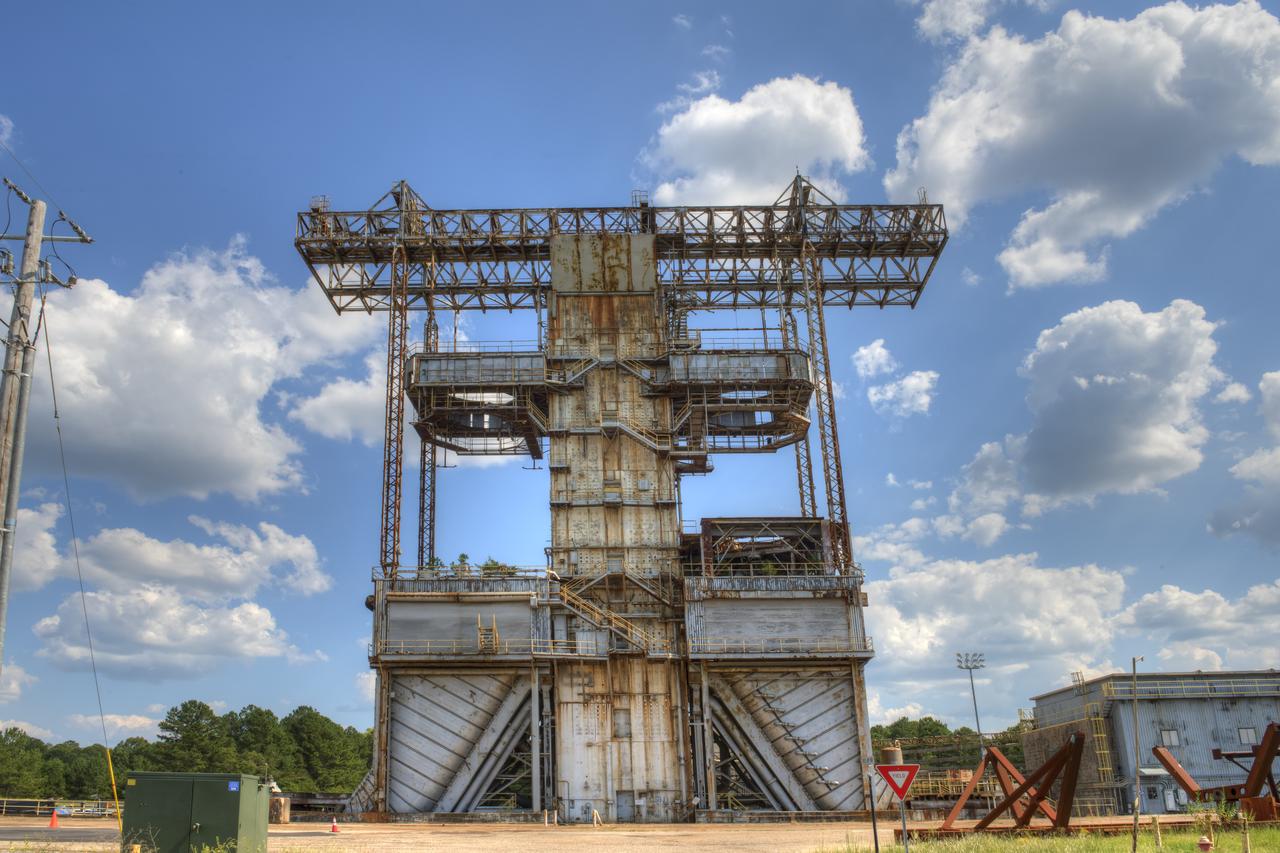
PROPULSION AND STRUCTURAL TEST FACILITY (BUILDING 4572) AT THE GEORGE C. MARSHALL SPACE FLIGHT CENTER IN HUNTSVILLE, ALABAMA
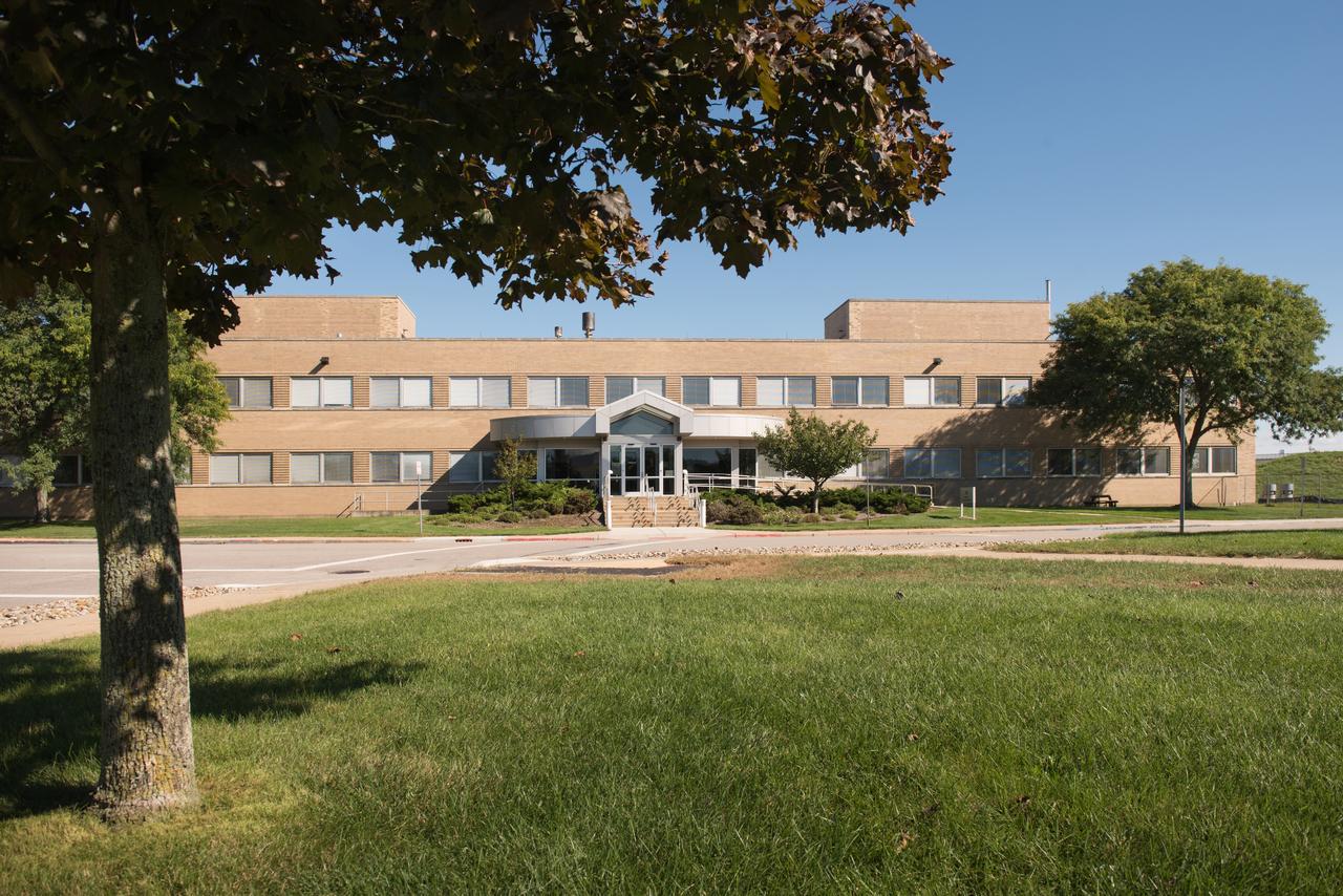
Materials and Structures Laboratory, Building 49
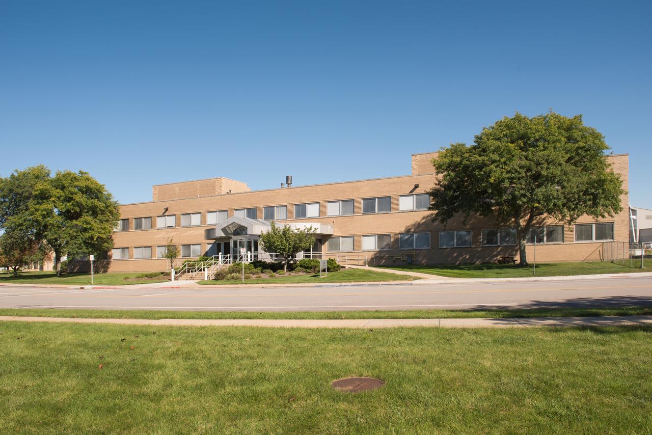
Materials and Structures Laboratory, Building 49
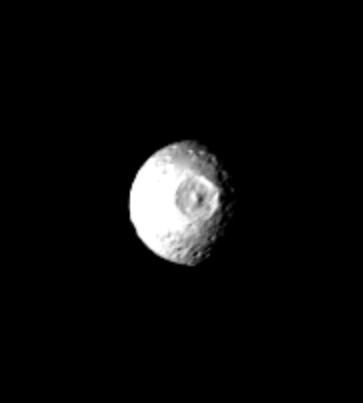
Mimas - Large Impact Structure

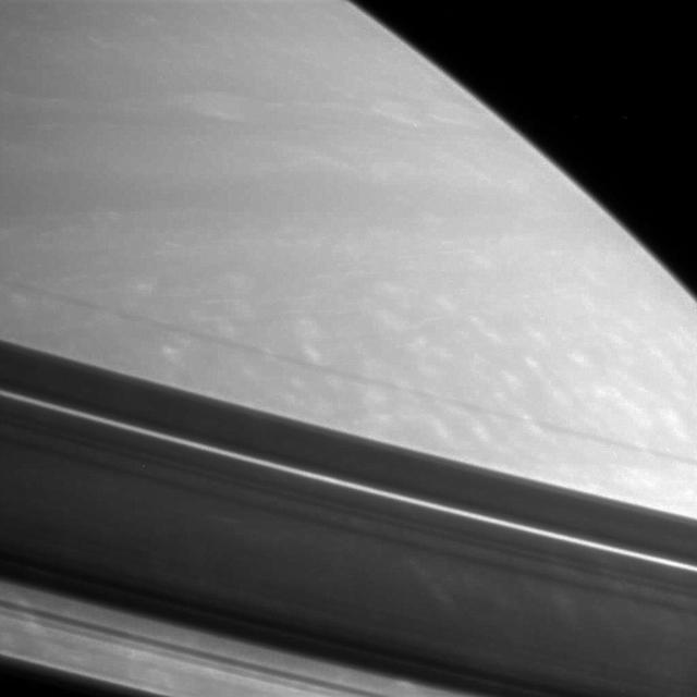
Saturn Ribbonlike Cloud Structure

D-Ring Structure
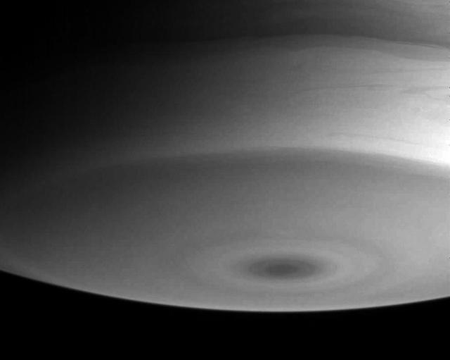
South Polar Structure
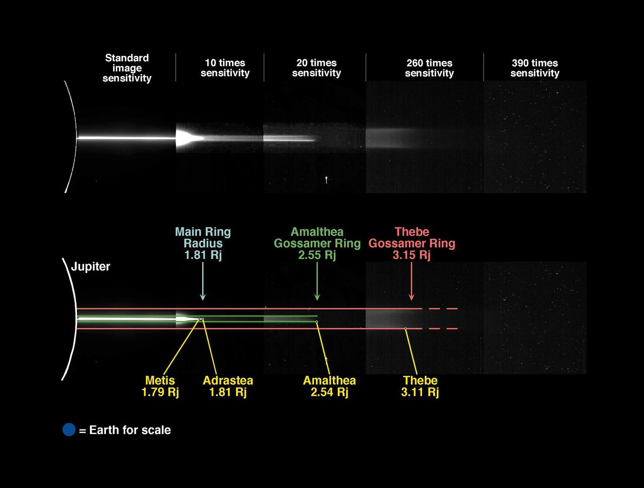
Jupiter Gossamer Ring Structure
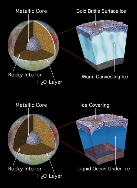
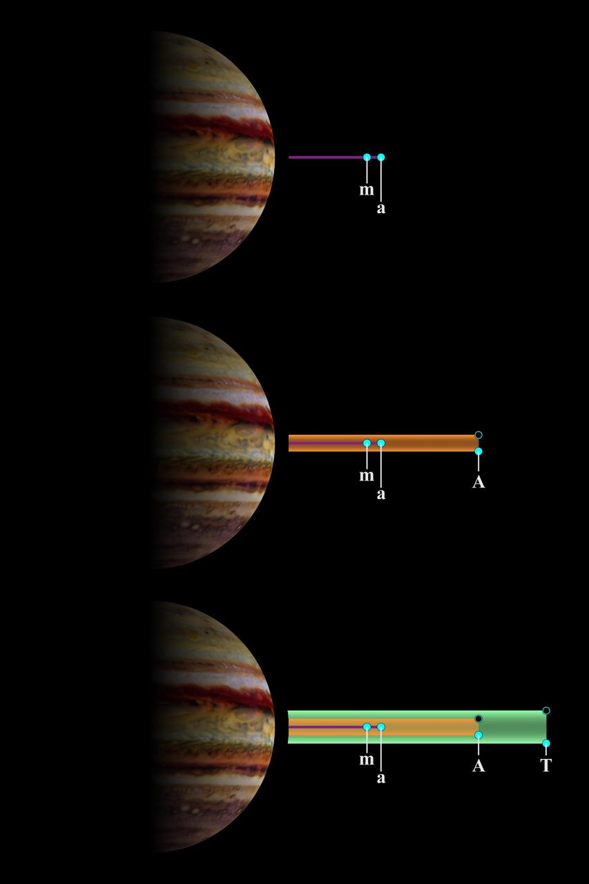
Model of Europa Subsurface Structure
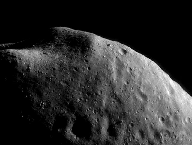
Interesting Structural Features on Eros
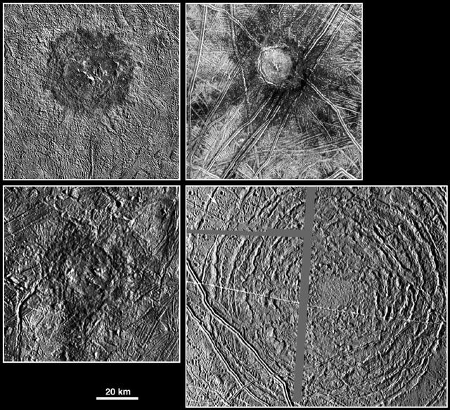
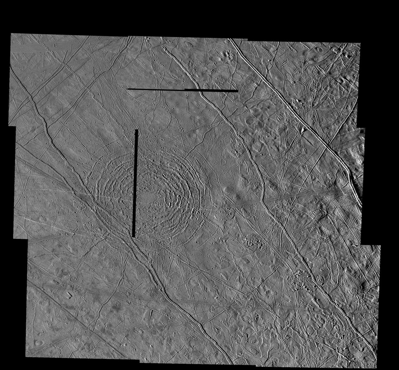
Large Impact Structures on Europa
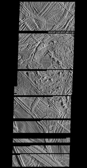
Structurally Complex Surface of Europa

Structure Along the Edge
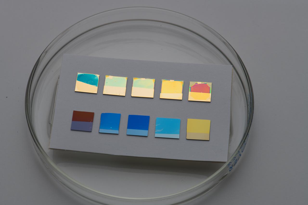
Dynamically tunable structural colors based on asymmetric Fabry-Perot cavities
Jupiter Main and Gossamer Ring Structures
The Tyre multi-ring Structure on Europa
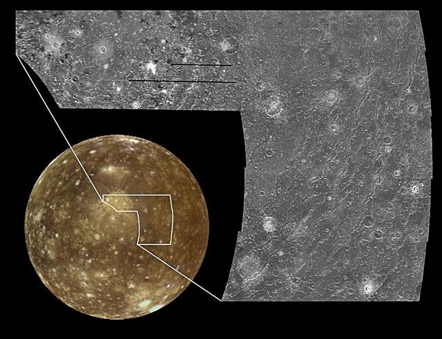
The Valhalla Multi-ring Structure on Callisto
Asgard Multi-Ring Structure on Callisto
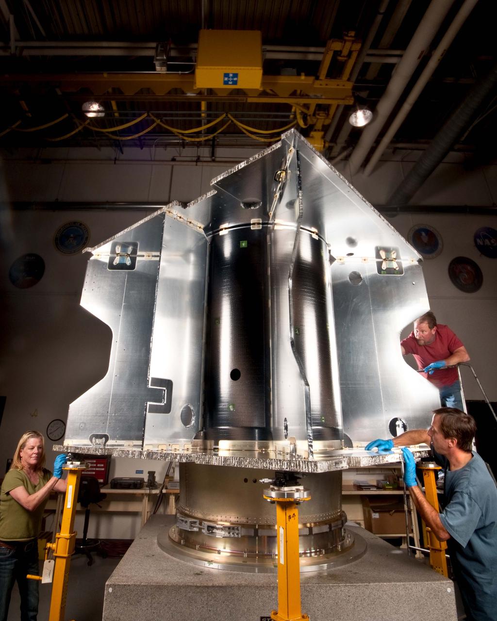
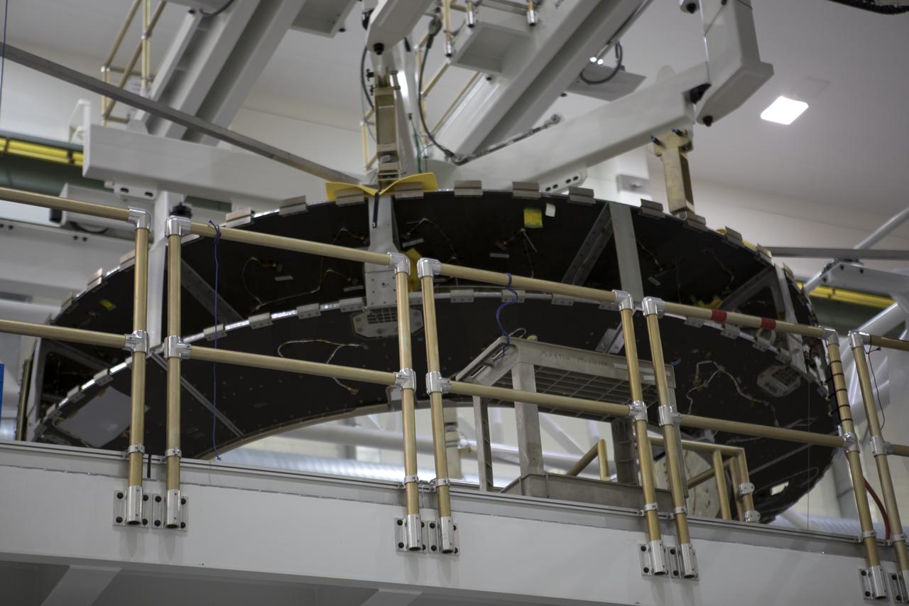
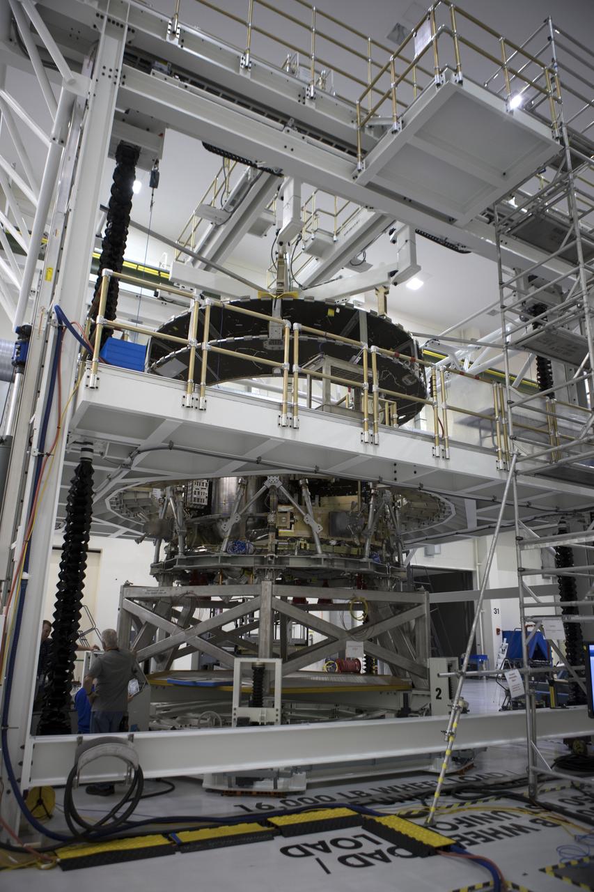
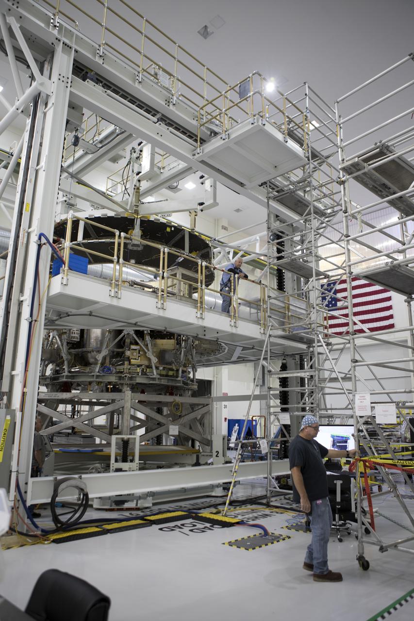
NASA's Mars Atmosphere and Volatile EvolutioN (MAVEN) mission has reached a new milestone. Lockheed Martin has completed building the primary structure of the MAVEN spacecraft at its Space Systems Company facility near Denver. The MAVEN spacecraft is scheduled to launch in November 2013 and will be the first mission devoted to understanding the Martian upper atmosphere. The mission's principal investigator is Bruce Jakosky from the Laboratory for Atmospheric and Space Physics at the University of Colorado. In the photo taken on Sept. 8, technicians from Lockheed Martin are inspecting the MAVEN primary structure following its recent completion at the company’s Composites Lab. The primary structure is cube shaped at 7.5 feet x 7.5 feet x 6.5 feet high (2.3 meters x 2.3 meters x 2 meters high). Built out of composite panels comprised of aluminum honeycomb sandwiched between graphite composite face sheets and attached to one another with metal fittings, the entire structure only weighs 275 pounds (125 kilograms). At the center of the structure is the 4.25 feet (1.3 meters) diameter core cylinder that encloses the hydrazine propellant tank and serves as the primary vertical load-bearing structure. The large tank will hold approximately 3,615 pounds (1640 kilograms) of fuel. To read more go to: <a href="http://www.nasa.gov/mission_pages/maven/news/maven-structure.html" rel="nofollow">www.nasa.gov/mission_pages/maven/news/maven-structure.html</a> Credit: Lockheed Martin <b><a href="http://www.nasa.gov/audience/formedia/features/MP_Photo_Guidelines.html" rel="nofollow">NASA image use policy.</a></b> <b><a href="http://www.nasa.gov/centers/goddard/home/index.html" rel="nofollow">NASA Goddard Space Flight Center</a></b> enables NASA’s mission through four scientific endeavors: Earth Science, Heliophysics, Solar System Exploration, and Astrophysics. Goddard plays a leading role in NASA’s accomplishments by contributing compelling scientific knowledge to advance the Agency’s mission. <b>Follow us on <a href="http://twitter.com/NASA_GoddardPix" rel="nofollow">Twitter</a></b> <b>Like us on <a href="http://www.facebook.com/pages/Greenbelt-MD/NASA-Goddard/395013845897?ref=tsd" rel="nofollow">Facebook</a></b> <b>Find us on <a href="http://instagrid.me/nasagoddard/?vm=grid" rel="nofollow">Instagram</a></b>
Dynamically tunable structural colors based on asymmetric Fabry-Perot cavities
Mission Adaptive Digital Composite Aerostructure Technologies (MADCAT) model in the 14x22 test section. Interior of Structure. For more information go to NASA.gov article. April 3, 2019 "What is MADCAT?" Flexing Wings for Efficient Flight
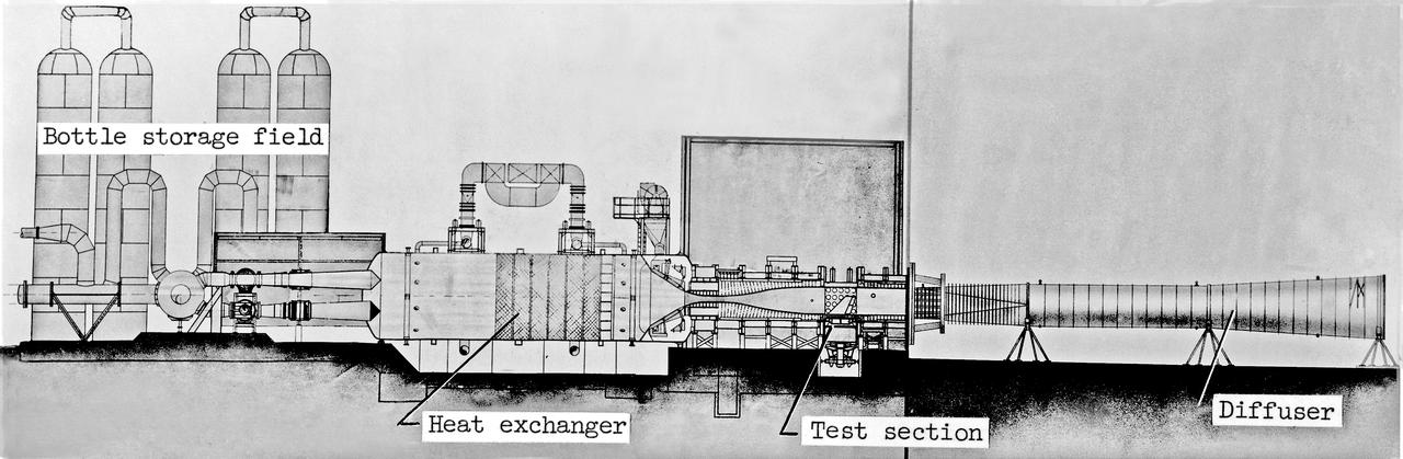
Scale Model of 9x6 Thermal Structures Tunnel: Image L-7256.01 is a Drawing Figure 12 in NASA Document L-1265. The Major components of the 9-by6-Foot Thermal Structures Tunnel. The 97 foot-long diffuser was added in 1960 to reduce noise.
SATURN S-1B STAGE (SA-T) WITH PROPULSION AND STRUCTURAL TEST FACILITY (BUILDING 4572) IN BACKGROUND
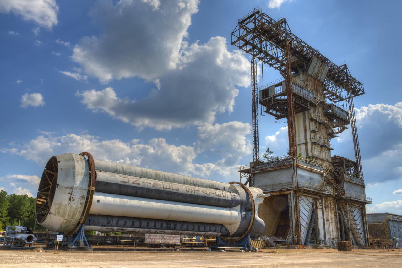
PROPULSION AND STRUCTURAL TEST FACILITY (BUILDING 4572) AT THE GEORGE C. MARSHALL SPACE FLIGHT CENTER IN HUNTSVILLE, ALABAMA WITH THE SATURN S-1B STAGE (SA-) IN FOREGROUND
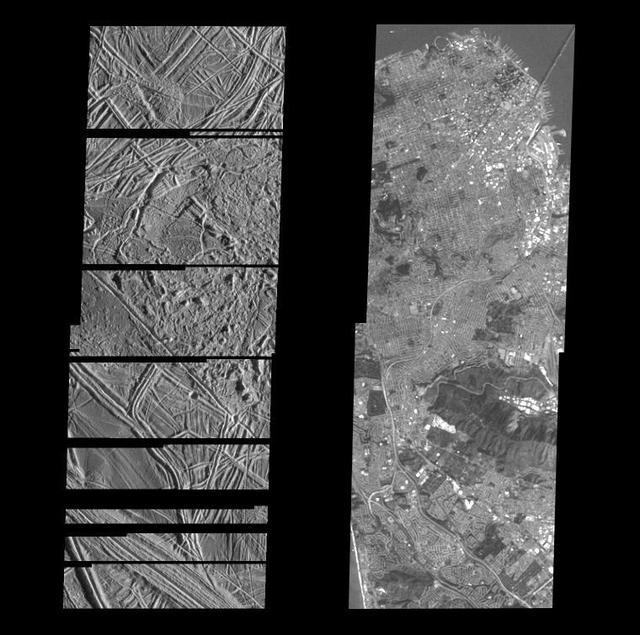
Structurally Complex Surface of Europa and similar scales on Earth

Temperature Profile from Pathfinder Atmospheric Structure Instrument
Unusual Structure on Crater Rim in West Utopia Planitia

Mission Adaptive Digital Composite Aerostructure Technologies (MADCAT) model in the 14x22 test section. Interior of structure. For more information go to NASA.gov article. April 3, 2019 "What is MADCAT?" Flexing Wings for Efficient Flight
Inside the Neil Armstrong Operations and Checkout Building high bay at NASA's Kennedy Space Center in Florida, operations are underway to lower the Orion crew module adapter structural test article onto the European Space Agency's service module structural test article. After the hardware is attached, the structure will be packed and shipped to Lockheed Martin's Denver facility to undergo testing. The Orion spacecraft will launch atop the agency's Space Launch System rocket on Exploration Mission-1 in 2019.
Inside the Neil Armstrong Operations and Checkout Building high bay at NASA's Kennedy Space Center in Florida, operations are underway to lower the Orion crew module adapter structural test article onto the European Space Agency's service module structural test article. After the hardware is attached, the structure will be packed and shipped to Lockheed Martin's Denver facility to undergo testing. The Orion spacecraft will launch atop the agency's Space Launch System rocket on Exploration Mission-1 in 2019.
Inside the Neil Armstrong Operations and Checkout Building high bay at NASA's Kennedy Space Center in Florida, operations are underway to lower the Orion crew module adapter structural test article onto the European Space Agency's service module structural test article. After the hardware is attached, the structure will be packed and shipped to Lockheed Martin's Denver facility to undergo testing. The Orion spacecraft will launch atop the agency's Space Launch System rocket on Exploration Mission-1 in 2019.
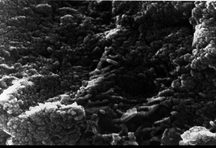
This electron microscope image shows tubular structures of likely Martian origin. These structures are very similar in size and shape to extremely tiny microfossils found in some Earth rocks. http://photojournal.jpl.nasa.gov/catalog/PIA00287
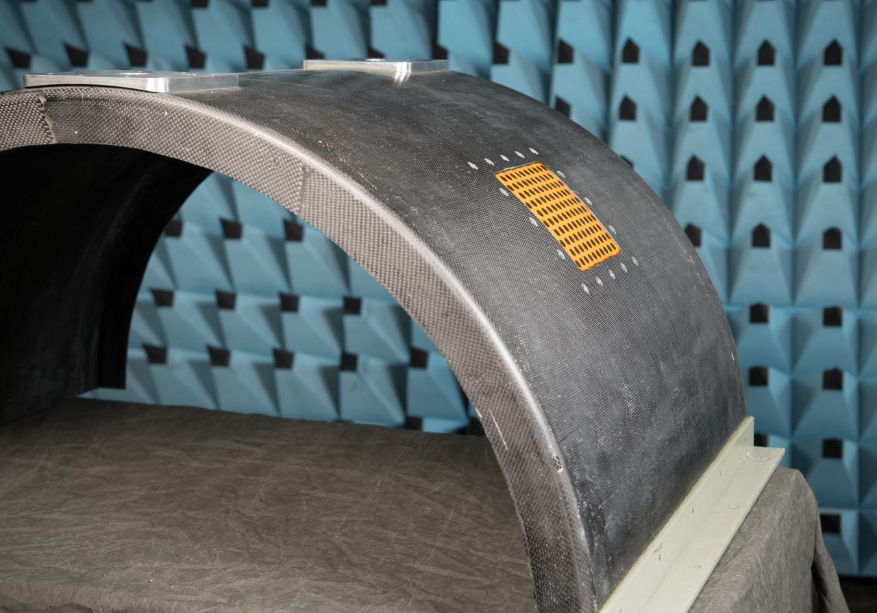
Curved Confocal Lightweight Antenna Structures for Aeronautical Communications Technologies, CLAS-ACT, Phased Array Antenna on Mock Carbon Fiber Fuselage
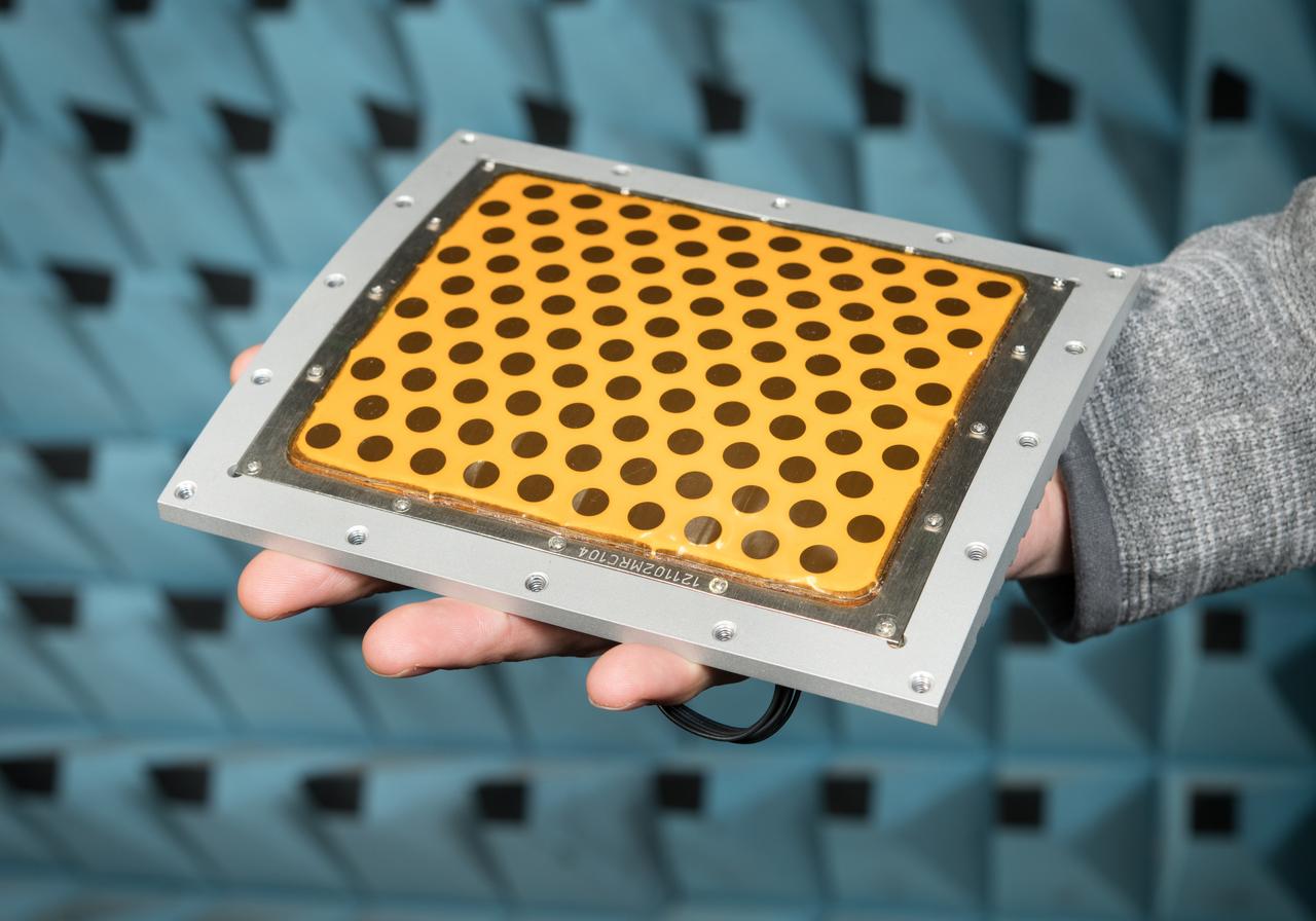
Curved Confocal Lightweight Antenna Structures for Aeronautical Communications Technologies, CLAS-ACT, Phased Array Antenna on Mock Carbon Fiber Fuselage
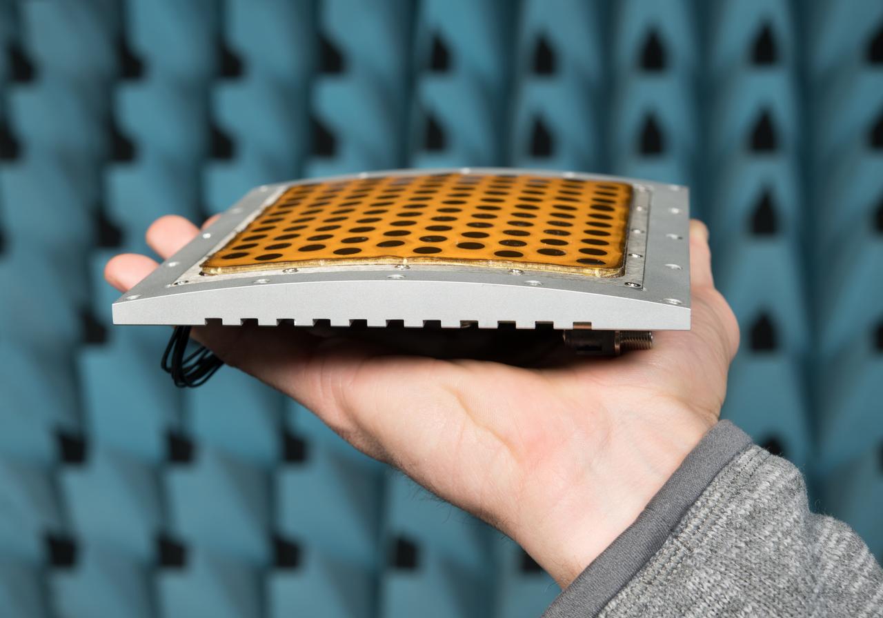
Curved Confocal Lightweight Antenna Structures for Aeronautical Communications Technologies, CLAS-ACT, Phased Array Antenna on Mock Carbon Fiber Fuselage
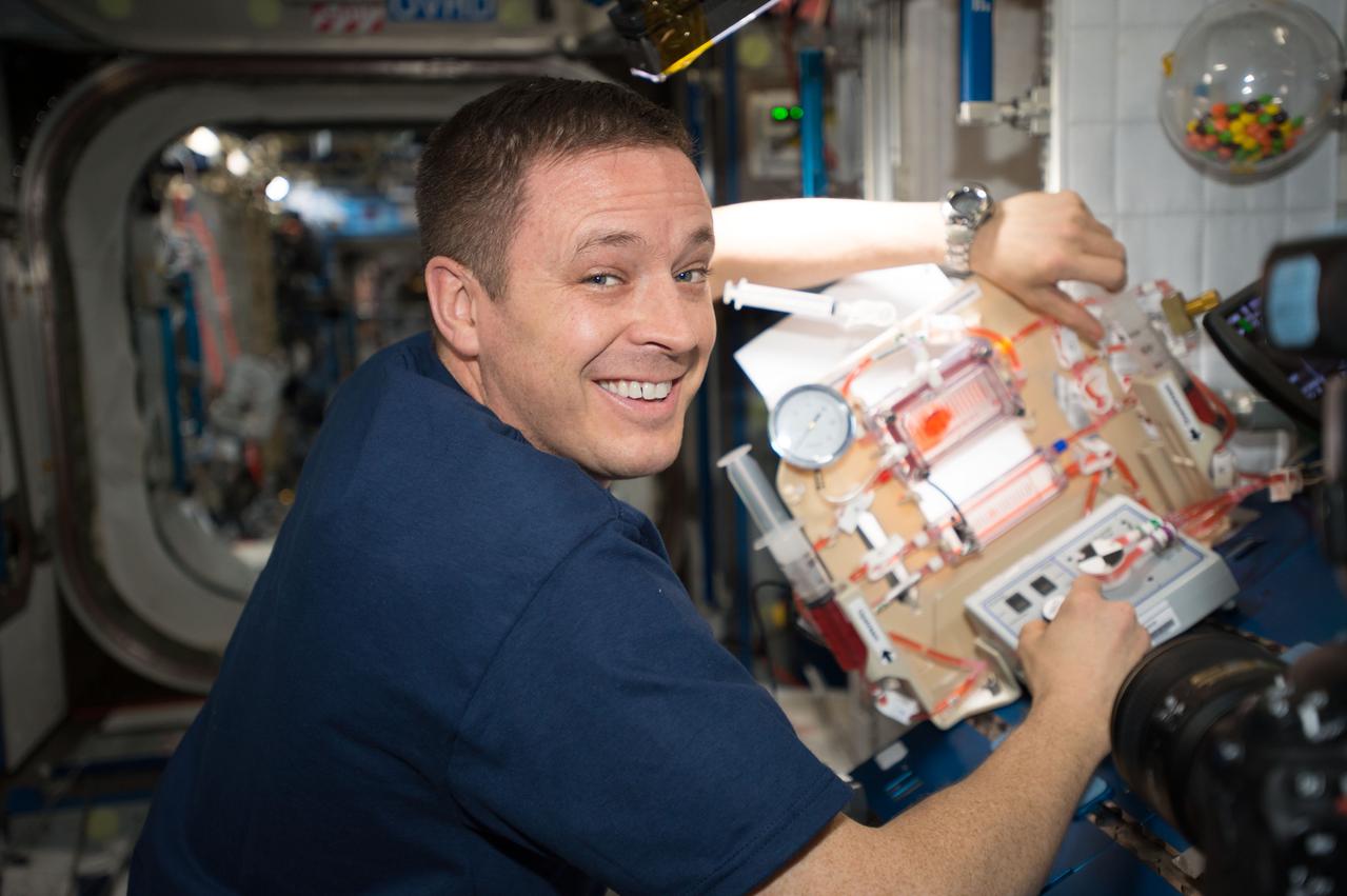
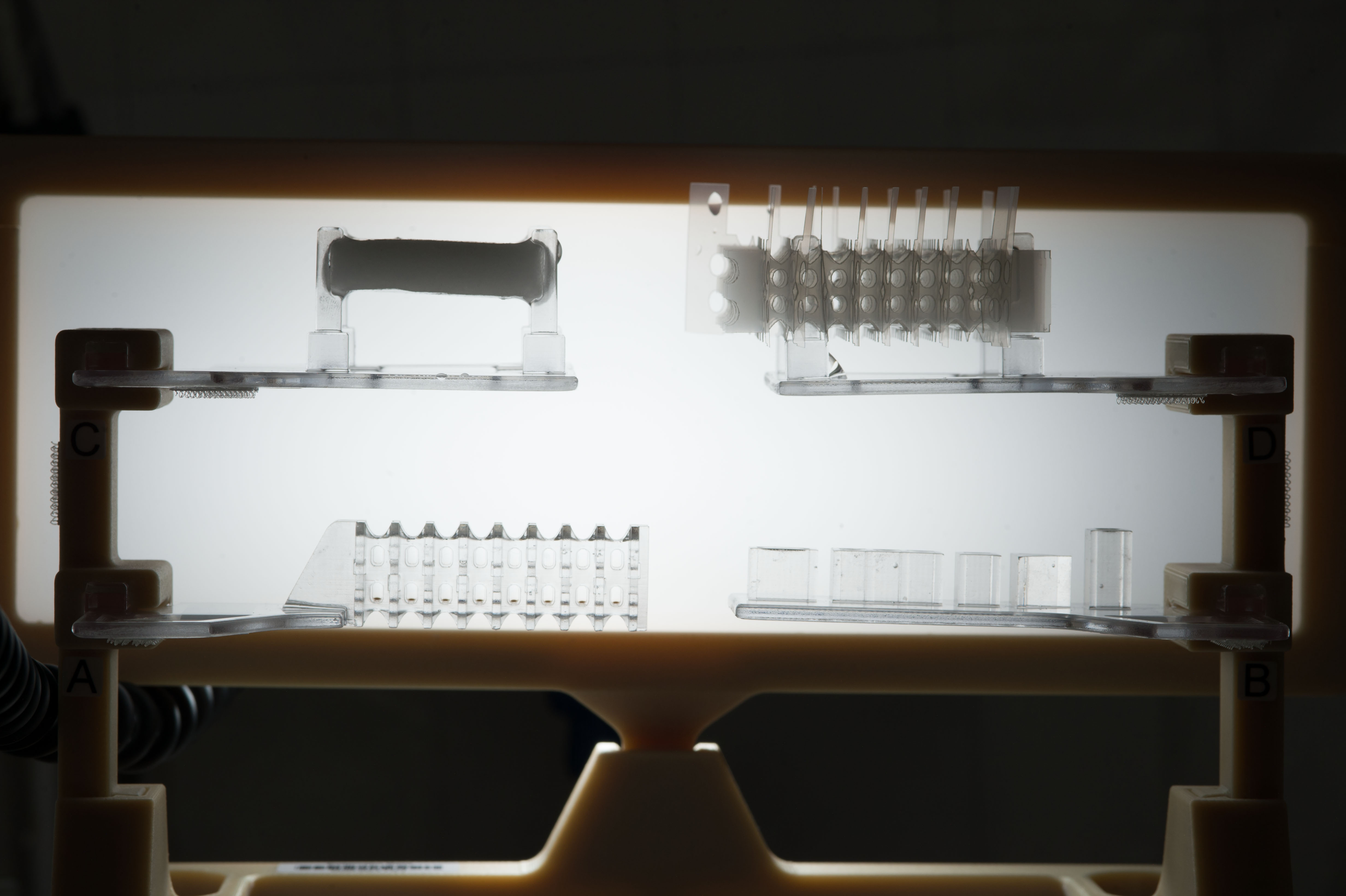
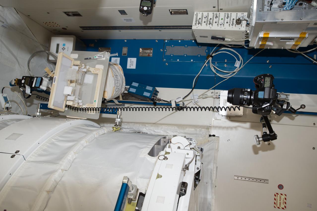
iss052e013146 (July 10, 2017) --- Astronaut Jack Fischer is photographed during setup of hardware for the Capillary Structures for Exploration Life Support (Capillary Structures) two sorbent demonstrations. The Capillary Structures for Exploration Life Support (Capillary Structures) investigation studies a new method using structures of specific shapes to manage fluid and gas mixtures. The investigation studies water recycling and carbon dioxide removal, benefiting future efforts to design lightweight, more reliable life support systems for future space missions.
iss052e013087 (7/10/2017) NASA astronaut Jack Fischer is photographed during setup of hardware for the Capillary Structures for Exploration Life Support (Capillary Structures) two sorbent demonstrations. The Capillary Structures for Exploration Life Support (Capillary Structures) investigation studies a new method using structures of specific shapes to manage fluid and gas mixtures. The investigation studies water recycling and carbon dioxide removal, benefiting future efforts to design lightweight, more reliable life support systems for future space missions.

Several structures in Saturn A ring are exposed near the Encke Gap in this image captured by NASA Cassini spacecraft. A peculiar kink can be seen in one particularly bright ringlet at the bottom right.
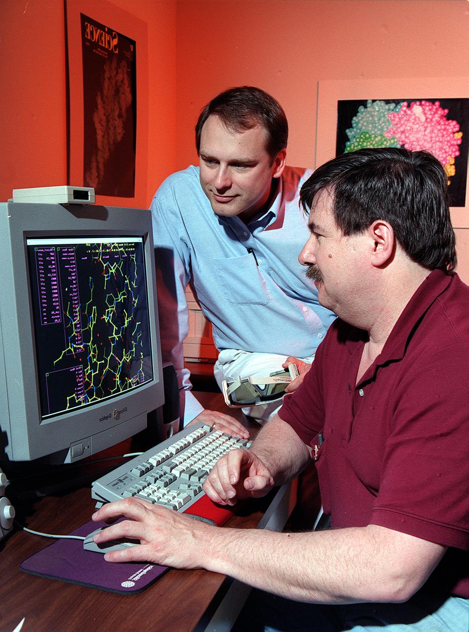
Dr. Marc Pusey (seated) and Dr. Craig Kundrot use computers to analyze x-ray maps and generate three-dimensional models of protein structures. With this information, scientists at Marshall Space Flight Center can learn how proteins are made and how they work. The computer screen depicts a proten structure as a ball-and-stick model. Other models depict the actual volume occupied by the atoms, or the ribbon-like structures that are crucial to a protein's function.
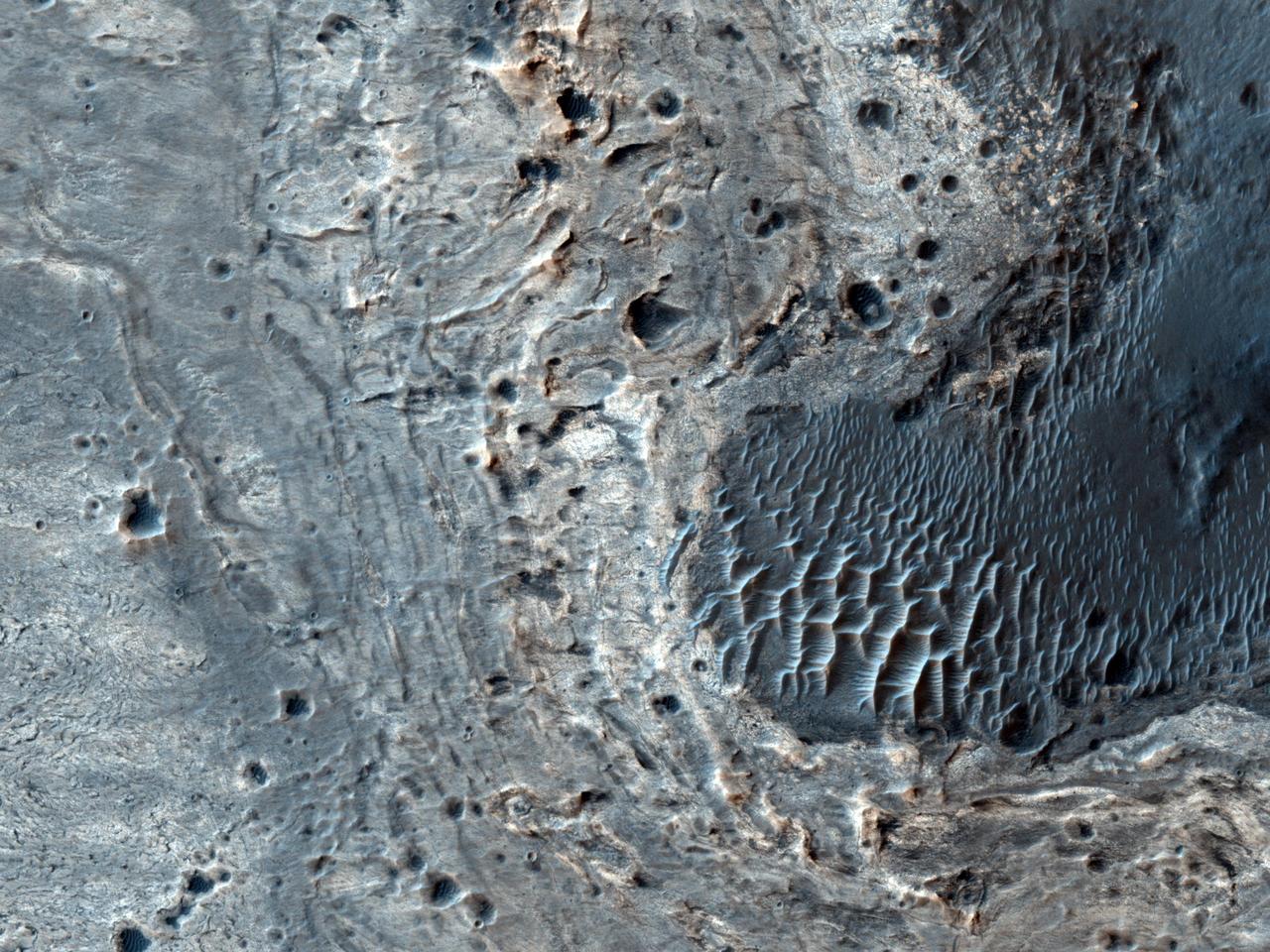
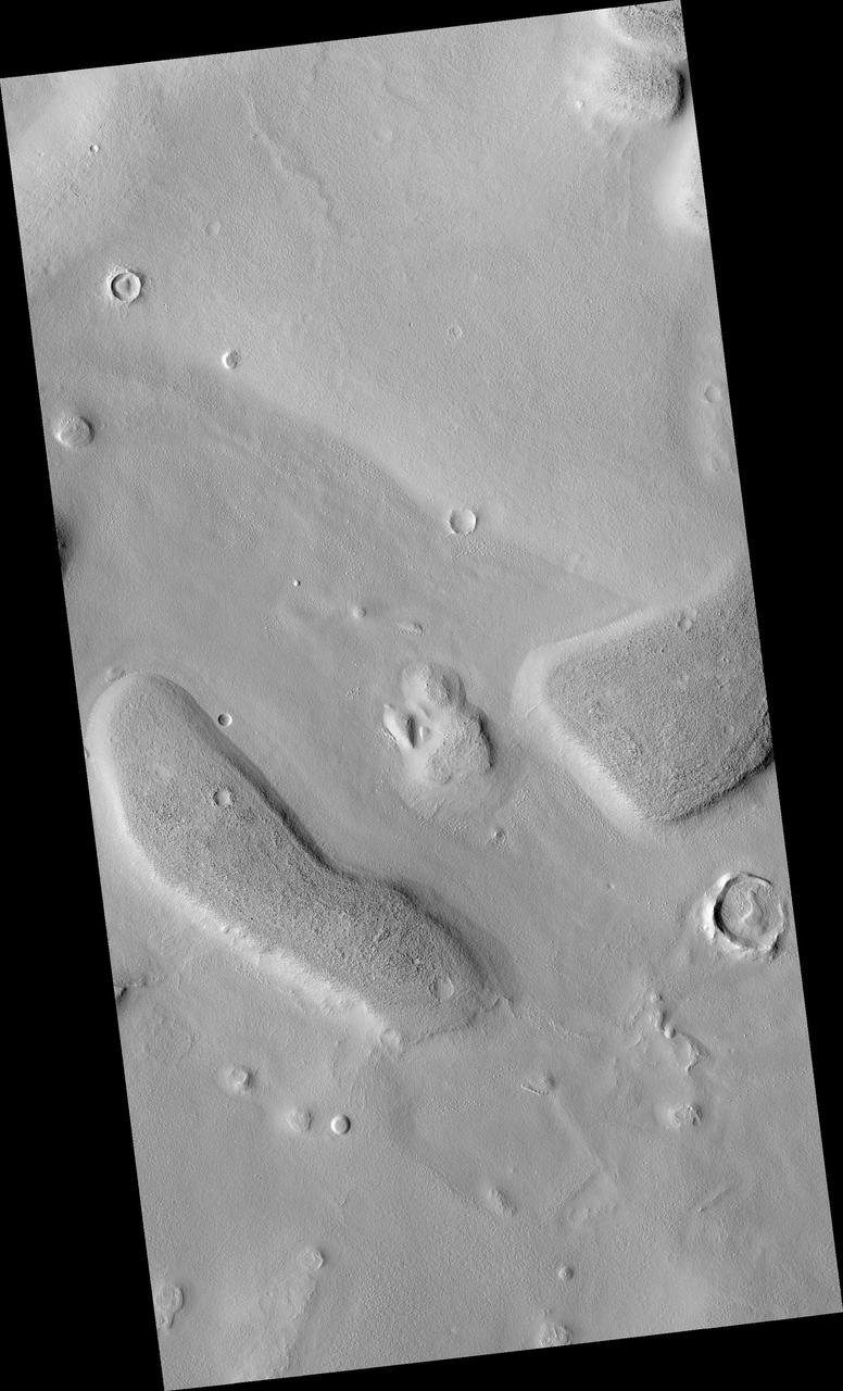
This image from NASA Mars Reconnaissance Orbiter shows a number of unusual, quasi-circular structures that apparently formed within bright flows in Meridiani Planum.

This illustration shows the core structure with ion propulsion system installed aboard NASA Dawn spacecraft.
Structural Heat Intercept, Insulation and Vibration Evaluation Rig, SHIIVER is installed in the In-Space Propulsion Chamber at NASA Glenn, Plum Brook Station
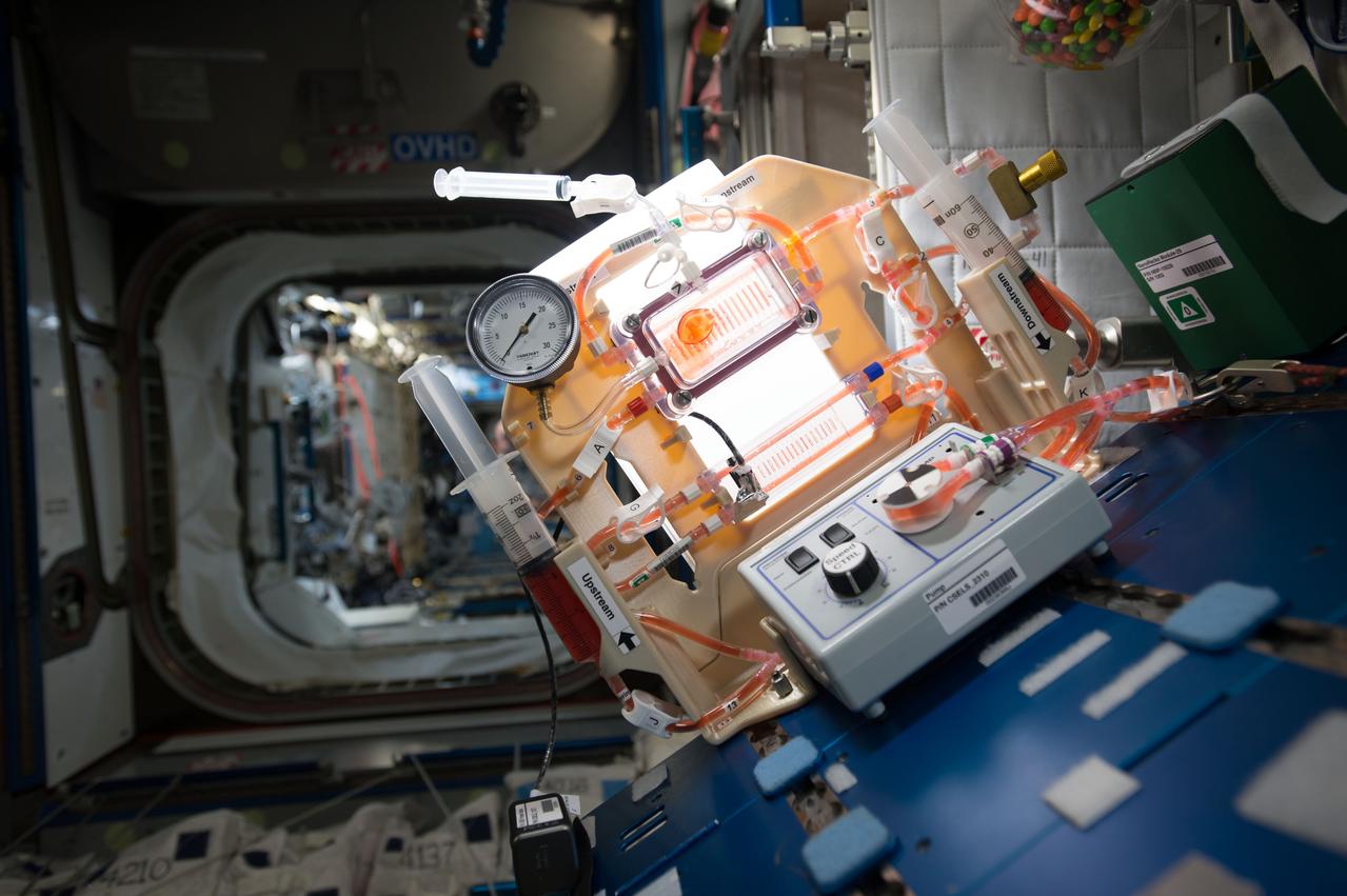
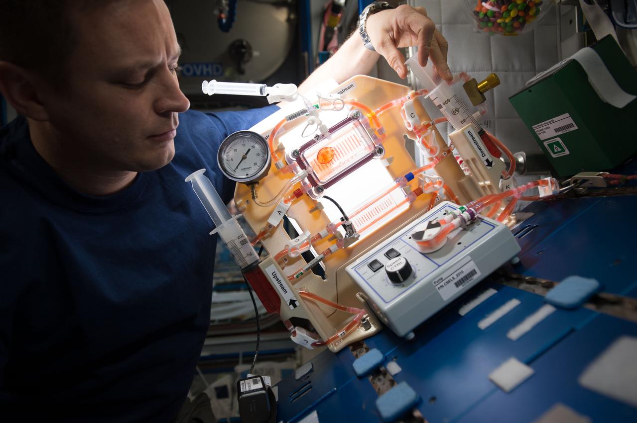
iss052e013081 (7/10/2017) --- The Capillary Structures for Exploration Life Support (Capillary Structures) investigation studies a new method using structures of specific shapes to manage fluid and gas mixtures. The investigation studies water recycling and carbon dioxide removal, benefiting future efforts to design lightweight, more reliable life support systems for future space missions.

Dr. Laurel Karr of NASA's Marshall Space Flight Center uses a stereo microscope to analyz protein crystals as a part of NASA's structural biology program.
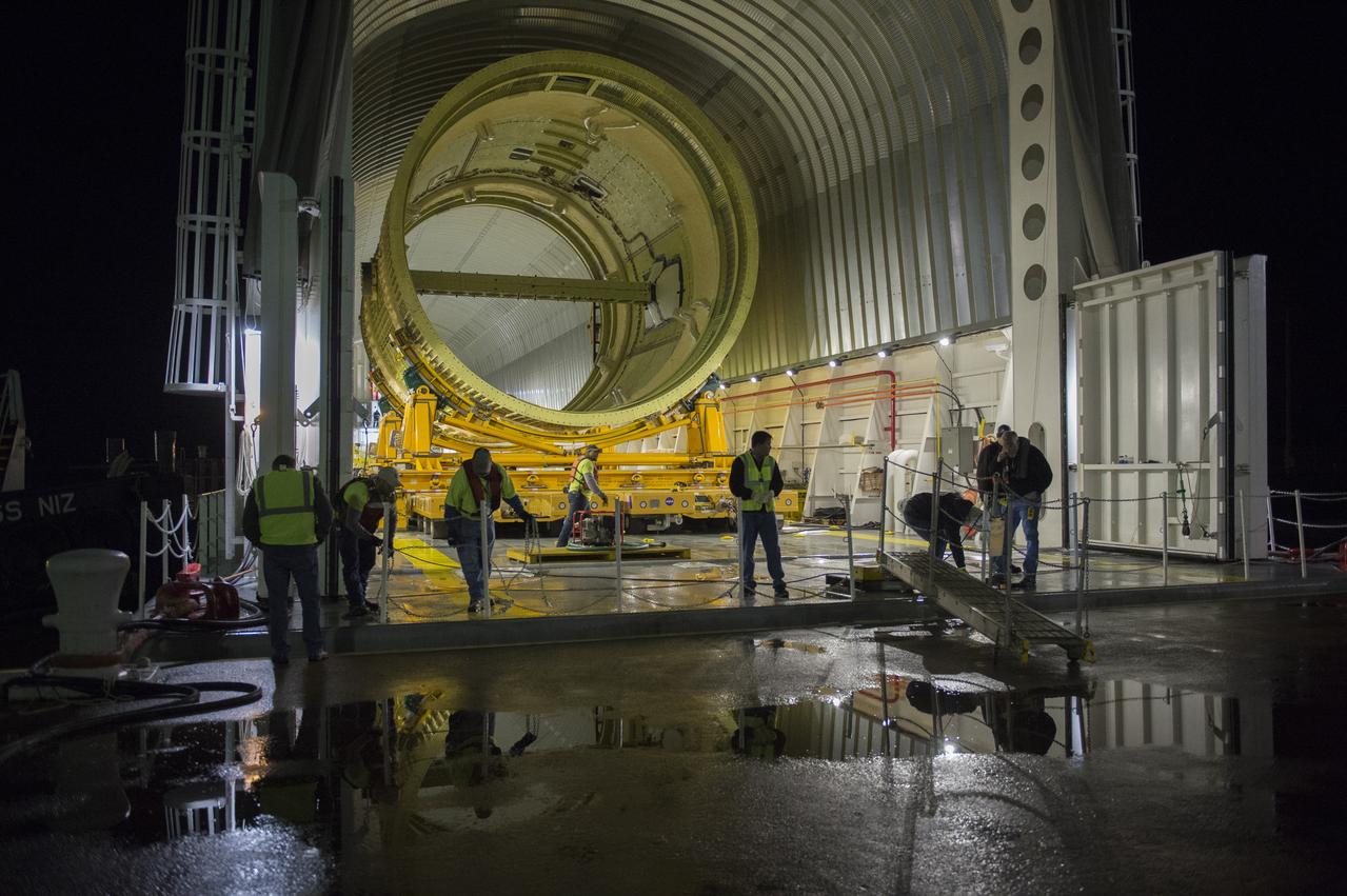
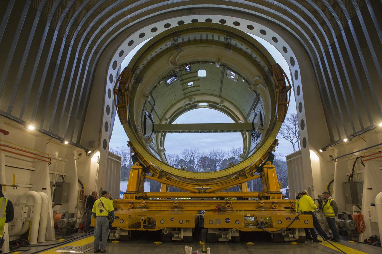
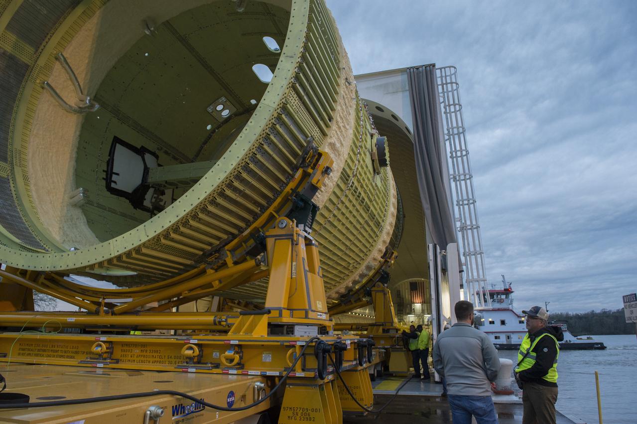
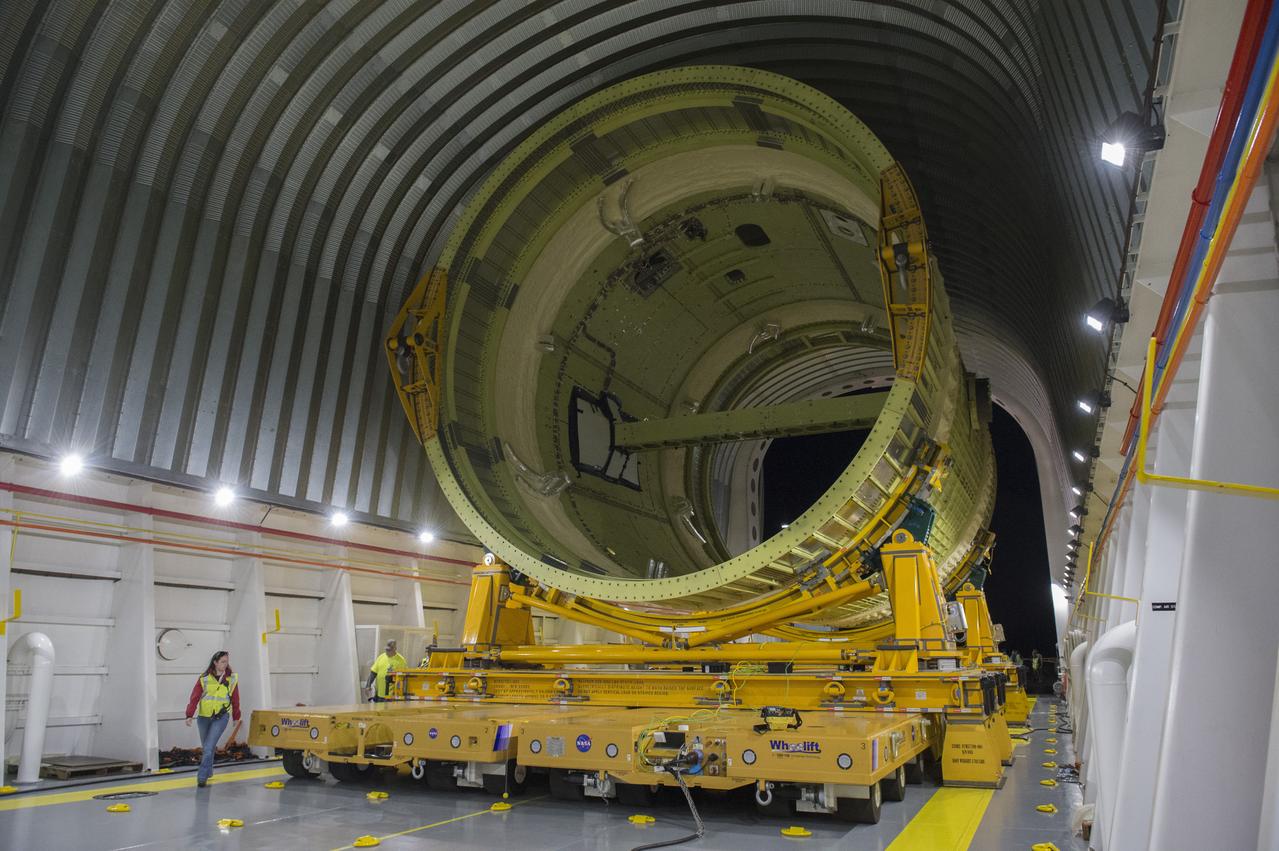
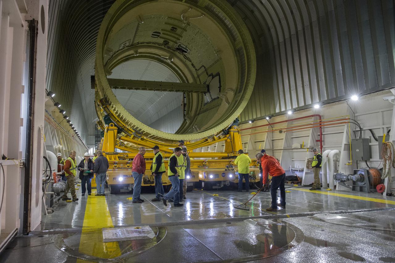
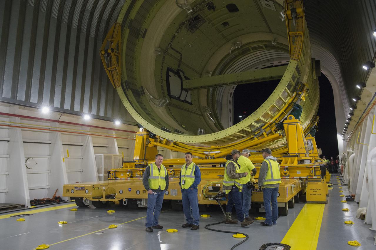
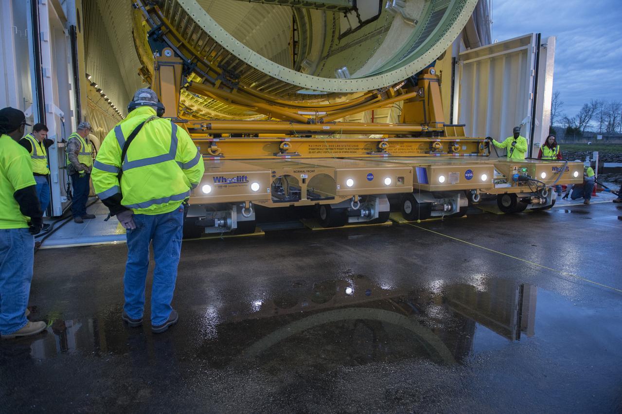
The SLS Stages Intertank Structural Test Assembly (STA) is rolling off the NASA Pegasus Barge at the MSFC Dock enroute to the MSFC 4619 Load Test Annex test facility for qualification testing
The SLS Stages Intertank Structural Test Assembly (STA) is rolling off the NASA Pegasus Barge at the MSFC Dock enroute to the MSFC 4619 Load Test Annex test facility for qualification testing
The SLS Stages Intertank Structural Test Assembly (STA) is rolling off the NASA Pegasus Barge at the MSFC Dock enroute to the MSFC 4619 Load Test Annex test facility for qualification testing
The SLS Stages Intertank Structural Test Assembly (STA) is rolling off the NASA Pegasus Barge at the MSFC Dock enroute to the MSFC 4619 Load Test Annex test facility for qualification testing
The SLS Stages Intertank Structural Test Assembly (STA) is rolling off the NASA Pegasus Barge at the MSFC Dock enroute to the MSFC 4619 Load Test Annex test facility for qualification testing
The SLS Stages Intertank Structural Test Assembly (STA) is rolling off the NASA Pegasus Barge at the MSFC Dock enroute to the MSFC 4619 Load Test Annex test facility for qualification testing
The SLS Stages Intertank Structural Test Assembly (STA) is rolling off the NASA Pegasus Barge at the MSFC Dock enroute to the MSFC 4619 Load Test Annex test facility for qualification testing
The SLS Stages Intertank Structural Test Assembly (STA) is rolling off the NASA Pegasus Barge at the MSFC Dock enroute to the MSFC 4619 Load Test Annex test facility for qualification testing
The SLS Stages Intertank Structural Test Assembly (STA) is rolling off the NASA Pegasus Barge at the MSFC Dock enroute to the MSFC 4619 Load Test Annex test facility for qualification testing
The SLS Stages Intertank Structural Test Assembly (STA) is rolling off the NASA Pegasus Barge at the MSFC Dock enroute to the MSFC 4619 Load Test Annex test facility for qualification testing
The SLS Stages Intertank Structural Test Assembly (STA) is rolling off the NASA Pegasus Barge at the MSFC Dock enroute to the MSFC 4619 Load Test Annex test facility for qualification testing

This prominent circular feature, known as the Richat Structure, in the Sahara desert of Mauritania is often noted by astronauts because it forms a conspicuous bull-eye on the otherwise rather featureless expanse of the desert.
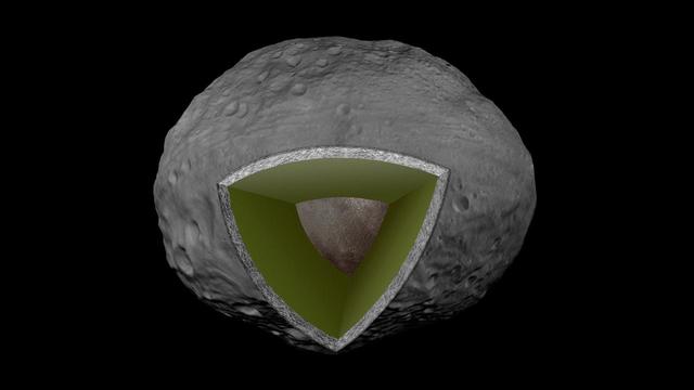
This artist concept shows the internal structure of the giant asteroid Vesta, based on data from NASA Dawn mission; the innermost core in brown, the mantle in green and the crust in gray.
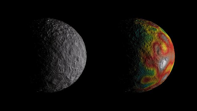
This frame from an animation shows Ceres as seen by NASA's Dawn spacecraft from its high-altitude mapping orbit at 913 miles (1,470 kilometers) above the surface. The colorful map overlaid at right shows variations in Ceres' gravity field measured by Dawn, and gives scientists hints about the dwarf planet's internal structure. Red colors indicate more positive values, corresponding to a stronger gravitational pull than expected, compared to scientists' pre-Dawn model of Ceres' internal structure; blue colors indicate more negative values, corresponding to a weaker gravitational pull. The animation was created by projecting a map of Ceres onto a rotating sphere. The image scale is about 450 feet (140 meters) per pixel. The animations are available at https://photojournal.jpl.nasa.gov/catalog/PIA22083
iss052e017187 (7/22/2017) --- A view taken of hardware for the Capillary Structures investigation in the Japanese Experiment Module (JEM). This investigation studies a new method using structures of specific shapes to manage fluid and gas mixtures. It also studies water recycling and carbon dioxide removal, benefiting future efforts to design lightweight, more reliable life support systems for future space missions.
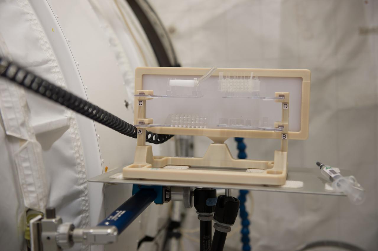
iss052e016481 (7/19/2017) --- A view taken of hardware for the Capillary Structures investigation in the Japanese Experiment Module (JEM). This investigation studies a new method using structures of specific shapes to manage fluid and gas mixtures. It also studies water recycling and carbon dioxide removal, benefiting future efforts to design lightweight, more reliable life support systems for future space missions.
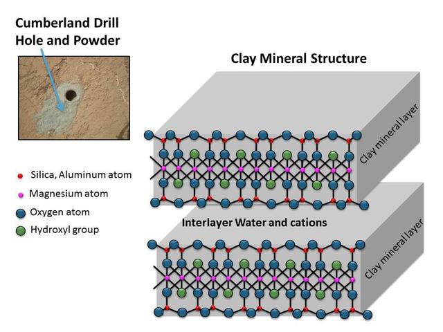
This schematic shows the atomic structure of the smallest units that make up the layers and interlayer region of clay minerals. This structure is similar to the clay mineral in drilled rock powder collected by NASA Curiosity Mars rover.

iss059e091418 (6/4/2019) --- View taken of the hardware for the Capillary Structures investigation in the Japanese Experiment Module (JEM) onboard the International Space Station (ISS). This investigation studies a new method using structures of specific shapes to manage fluid and gas mixtures. It also studies water recycling and carbon dioxide removal, benefitting future efforts to design lightweight, more reliable life support systems for future space missions.
The SLS Stages Intertank Structural Test Assembly (STA) is rolling off the NASA Pegasus Barge at the MSFC Dock enroute to the MSFC 4619 Load Test Annex test facility for qualification testing. STA hardware completely free of barge and flanked by tug boats.
The SLS Stages Intertank Structural Test Assembly (STA) is rolling off the NASA Pegasus Barge at the MSFC Dock enroute to the MSFC 4619 Load Test Annex test facility for qualification testing. STA emerges from Barge Pegasus.
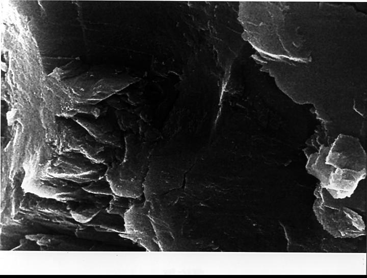
In the center of this electron microscope image of a small chip from a meteorite are several tiny structures that are possible microscopic fossils of primitive, bacteria-like organisms that may have lived on Mars more than 3.6 billion years ago. http://photojournal.jpl.nasa.gov/catalog/PIA00283

Cindy Barnes of University Space Research Association (USRA) at NASA's Marshall Space Flight Center pipettes a protein solution in preparation to grow crystals as part of NASA's structural biology program. Research on Earth helps scientists define conditions and specimens they will use in space experiments.
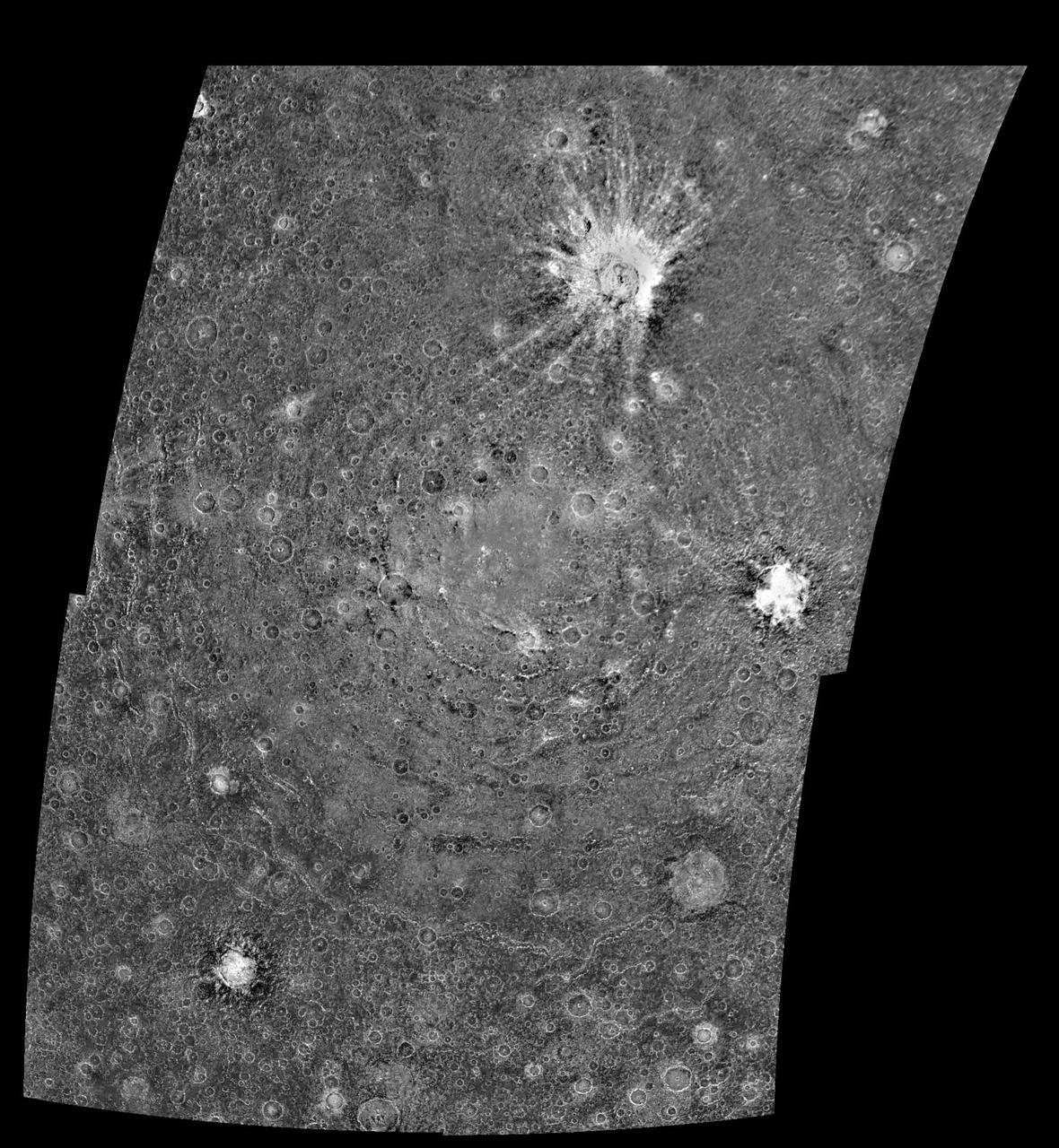
This four-frame mosaic shows the ancient impact structure Asgard on Jupiter's moon Callisto. This image is centered at 30 degrees north, 142 degrees west. The Asgard structure is approximately 1700 km across (1,056 mi) and consists of a bright central zone surrounded by discontinuous rings. The rings are tectonic features with scarps near the central zone and troughs at the outer margin. Several large impacts have smashed into Callisto after the formation of Asgard. The very young, bright-rayed crater Burr is located on the northern part of Asgard. This mosaic has been projected to show a uniform scale between the four mosaiced images. The image was processed by Deutsche Forschungsanstalt fuer Luftund Raumfahrt e.V., Berlin, Germany. This image was taken on November 4, 1996, at a distance of 111,891 kilometers (69,070 miles) by the solid state imaging television camera onboard the Galileo spacecraft during its third orbit around Jupiter. http://photojournal.jpl.nasa.gov/catalog/PIA00517

On June 28, 2019, NASA's InSight lander used its robotic arm to move the support structure for its digging instrument, informally called the "mole." This view was captured by the Instrument Deployment Camera on the spacecraft's robotic arm. Lifting the support structure had been done in three steps, a little bit at a time, to ensure the mole wasn't pulled out of the soil. Moving the structure out of the way will give the InSight team a better look at the mole and allow them to try to help it dig. https://photojournal.jpl.nasa.gov/catalog/PIA23309
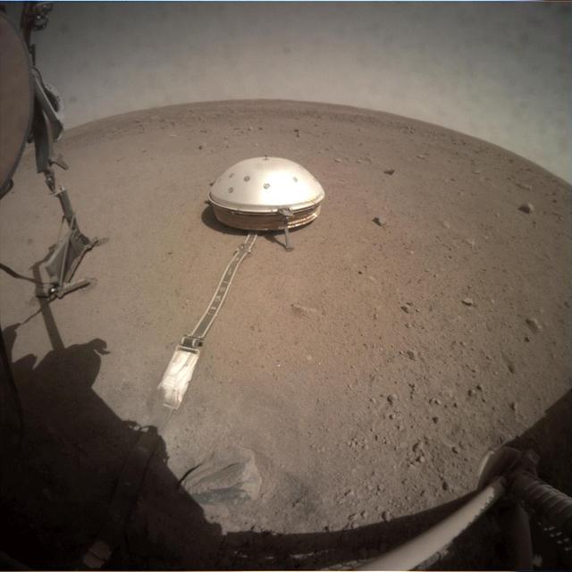
On June 28, 2019, NASA's InSight lander used its robotic arm to move the support structure for its digging instrument, informally called the "mole." This view was captured by the fisheye Instrument Context Camera under the lander's deck. Lifting the support structure had been done in three steps, a little bit at a time, to ensure the mole wasn't pulled out of the soil. Moving the structure out of the way will give the InSight team a better look at the mole and allow them to try to help it dig. https://photojournal.jpl.nasa.gov/catalog/PIA23308
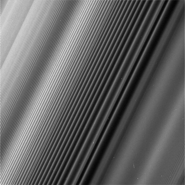
This view from NASA's Cassini spacecraft shows a wave structure in Saturn's rings known as the Janus 2:1 spiral density wave. Resulting from the same process that creates spiral galaxies, spiral density waves in Saturn's rings are much more tightly wound. In this case, every second wave crest is actually the same spiral arm which has encircled the entire planet multiple times. This is the only major density wave visible in Saturn's B ring. Most of the B ring is characterized by structures that dominate the areas where density waves might otherwise occur, but this innermost portion of the B ring is different. The radius from Saturn at which the wave originates (toward lower-right in this image) is 59,796 miles (96,233 kilometers) from the planet. At this location, ring particles orbit Saturn twice for every time the moon Janus orbits once, creating an orbital resonance. The wave propagates outward from the resonance (and away from Saturn), toward upper-left in this view. For reasons researchers do not entirely understand, damping of waves by larger ring structures is very weak at this location, so this wave is seen ringing for hundreds of bright wave crests, unlike density waves in Saturn's A ring. The image gives the illusion that the ring plane is tilted away from the camera toward upper-left, but this is not the case. Because of the mechanics of how this kind of wave propagates, the wavelength decreases with distance from the resonance. Thus, the upper-left of the image is just as close to the camera as the lower-right, while the wavelength of the density wave is simply shorter. This wave is remarkable because Janus, the moon that generates it, is in a strange orbital configuration. Janus and Epimetheus share practically the same orbit and trade places every four years. Every time one of those orbit swaps takes place, the ring at this location responds, spawning a new crest in the wave. The distance between any pair of crests corresponds to four years' worth of the wave propagating downstream from the resonance, which means the wave seen here encodes many decades' worth of the orbital history of Janus and Epimetheus. According to this interpretation, the part of the wave at the very upper-left of this image corresponds to the positions of Janus and Epimetheus around the time of the Voyager flybys in 1980 and 1981, which is the time at which Janus and Epimetheus were first proven to be two distinct objects (they were first observed in 1966). Epimetheus also generates waves at this location, but they are swamped by the waves from Janus, since Janus is the larger of the two moons. This image was taken on June 4, 2017, with the Cassini spacecraft narrow-angle camera. The image was acquired on the sunlit side of the rings from a distance of 47,000 miles (76,000 kilometers) away from the area pictured. The image scale is 1,730 feet (530 meters) per pixel. The phase angle, or sun-ring-spacecraft angle, is 90 degrees. https://photojournal.jpl.nasa.gov/catalog/PIA21627
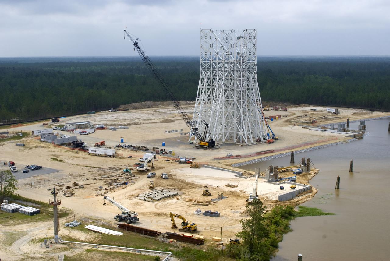
Structural steel work is completed on the 235-foot A-3 Test Stand at NASA's John C. Stennis Space Center. Stennis engineers celebrated this key milestone in construction April 9.
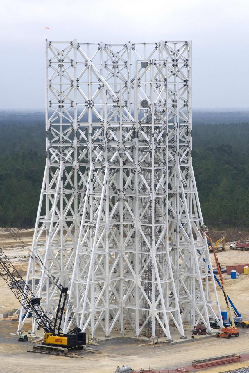
Structural steel work is completed on the 235-foot A-3 Test Stand at NASA's John C. Stennis Space Center. Stennis engineers celebrated this key milestone in construction April 9.
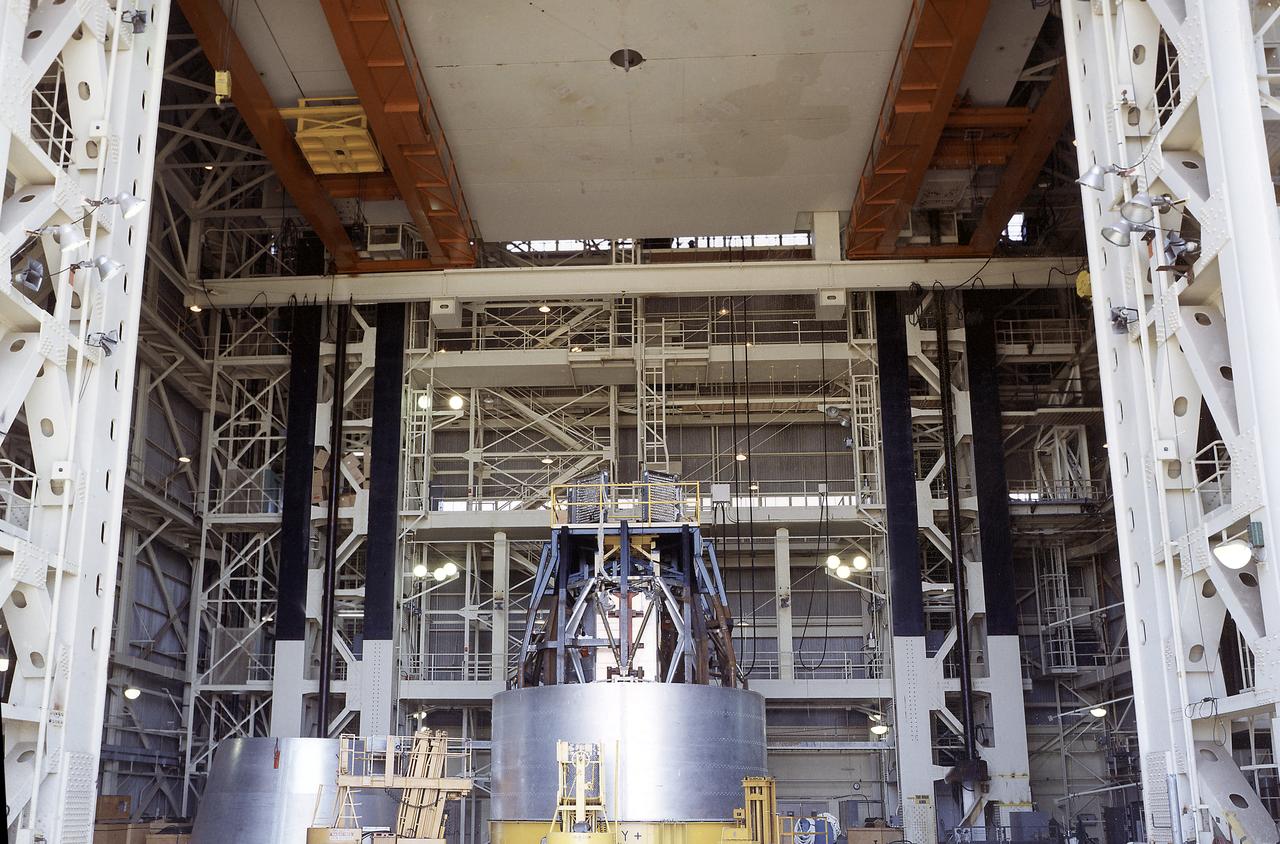
The Apollo Telescope Mount (ATM) was one of four major components of Skylab that were designed and constructed under the management of the Marshall Space Flight Center (MSFC). In this photograph, an ATM is seen sitting inside the MSFC's Structural Load Test Arnex where the main structural elements were simulated under launch conditions.
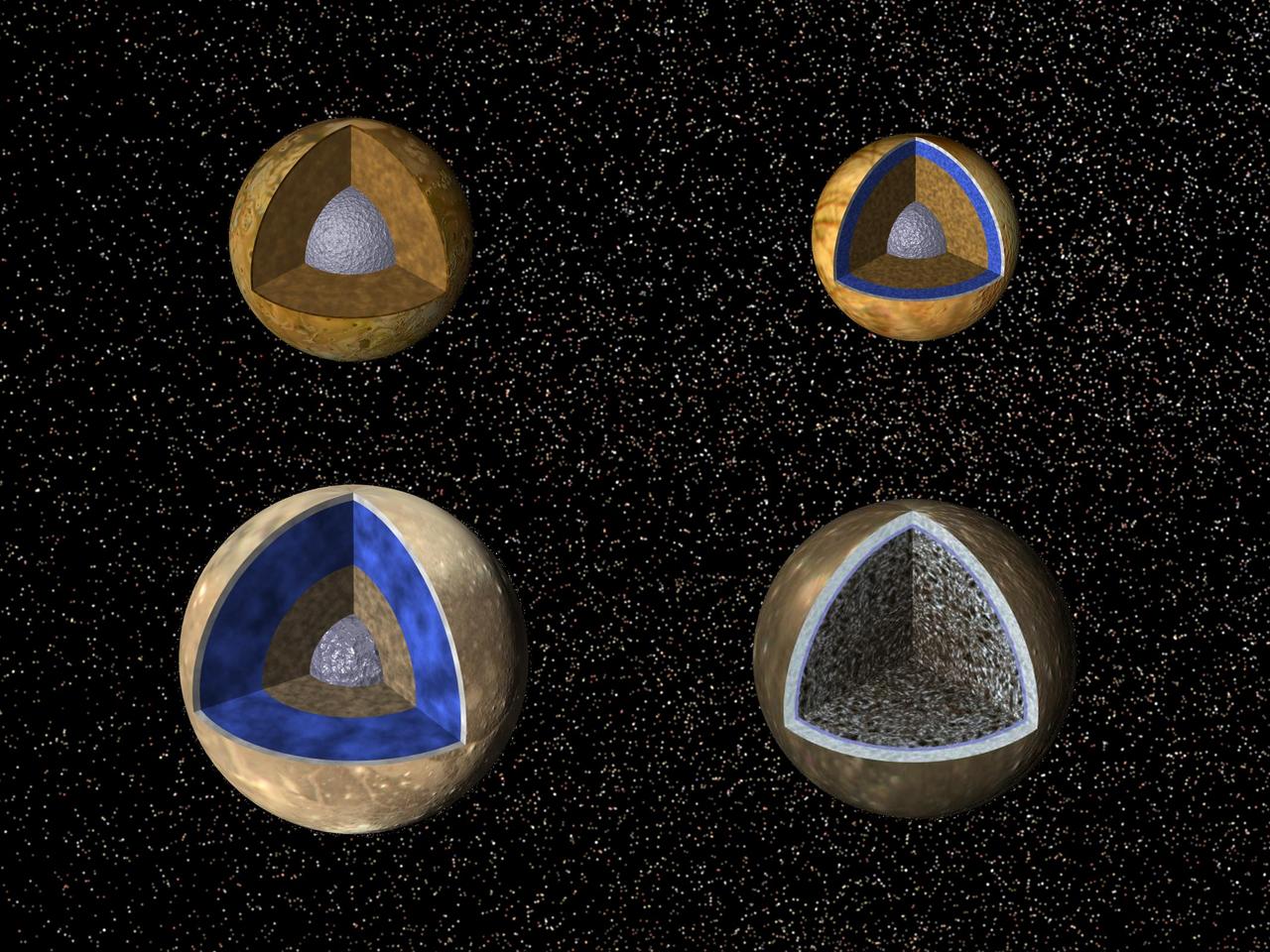
Cutaway views of the possible internal structures of the Galilean satellites. Ganymede at lower left, Callisto at lower right, Io on upper left, and Europa on upper right in a combined biew from NASA Galileo and Voyager spacecraft.
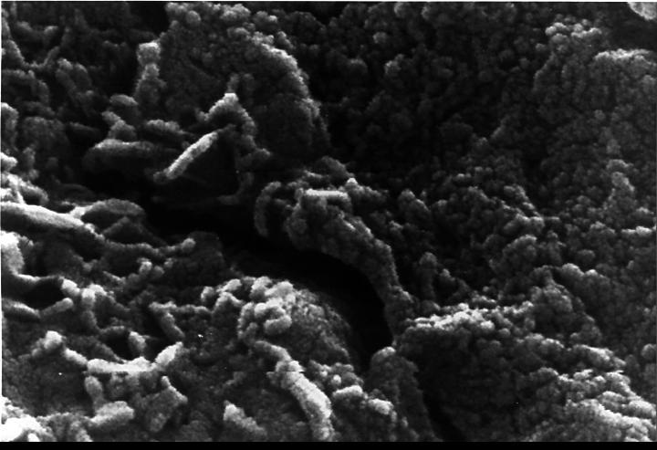
This electron microscope image shows extremely tiny tubular structures that are possible microscopic fossils of bacteria-like organisms that may have lived on Mars more than 3.6 billion years ago. http://photojournal.jpl.nasa.gov/catalog/PIA00285
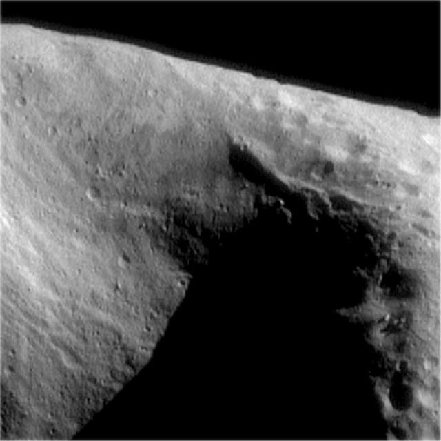
![A portion of the central zone of the large impact structure Valhalla on Jupiter's moon Callisto was imaged by the Galileo spacecraft on November 4, 1996. The area shown here is centered at 16 degrees north, 55 degrees west and is about seven miles (11 kilometers) across. This is the highest resolution picture ever taken of Callisto and shows features as small as 200 feet (60 meters) across. The formation of Valhalla occurred early in Callisto's history; however, the central zone shown here is probably younger than Valhalla's surrounding structure. This newly [sic] acquired picture shows some small craters, although they have been softened or modified by downslope movement of debris, revealing bright ice-rich surfaces. In contrast to other areas on Callisto, most of the very smallest craters appear to have been completely obliterated. This image was taken by the solid state imaging television camera onboard the Galileo spacecraft during its third orbit around Jupiter, at a distance of 757 miles (1,219 kilometers). http://photojournal.jpl.nasa.gov/catalog/PIA00516](https://images-assets.nasa.gov/image/PIA00516/PIA00516~thumb.jpg)
A portion of the central zone of the large impact structure Valhalla on Jupiter's moon Callisto was imaged by the Galileo spacecraft on November 4, 1996. The area shown here is centered at 16 degrees north, 55 degrees west and is about seven miles (11 kilometers) across. This is the highest resolution picture ever taken of Callisto and shows features as small as 200 feet (60 meters) across. The formation of Valhalla occurred early in Callisto's history; however, the central zone shown here is probably younger than Valhalla's surrounding structure. This newly [sic] acquired picture shows some small craters, although they have been softened or modified by downslope movement of debris, revealing bright ice-rich surfaces. In contrast to other areas on Callisto, most of the very smallest craters appear to have been completely obliterated. This image was taken by the solid state imaging television camera onboard the Galileo spacecraft during its third orbit around Jupiter, at a distance of 757 miles (1,219 kilometers). http://photojournal.jpl.nasa.gov/catalog/PIA00516
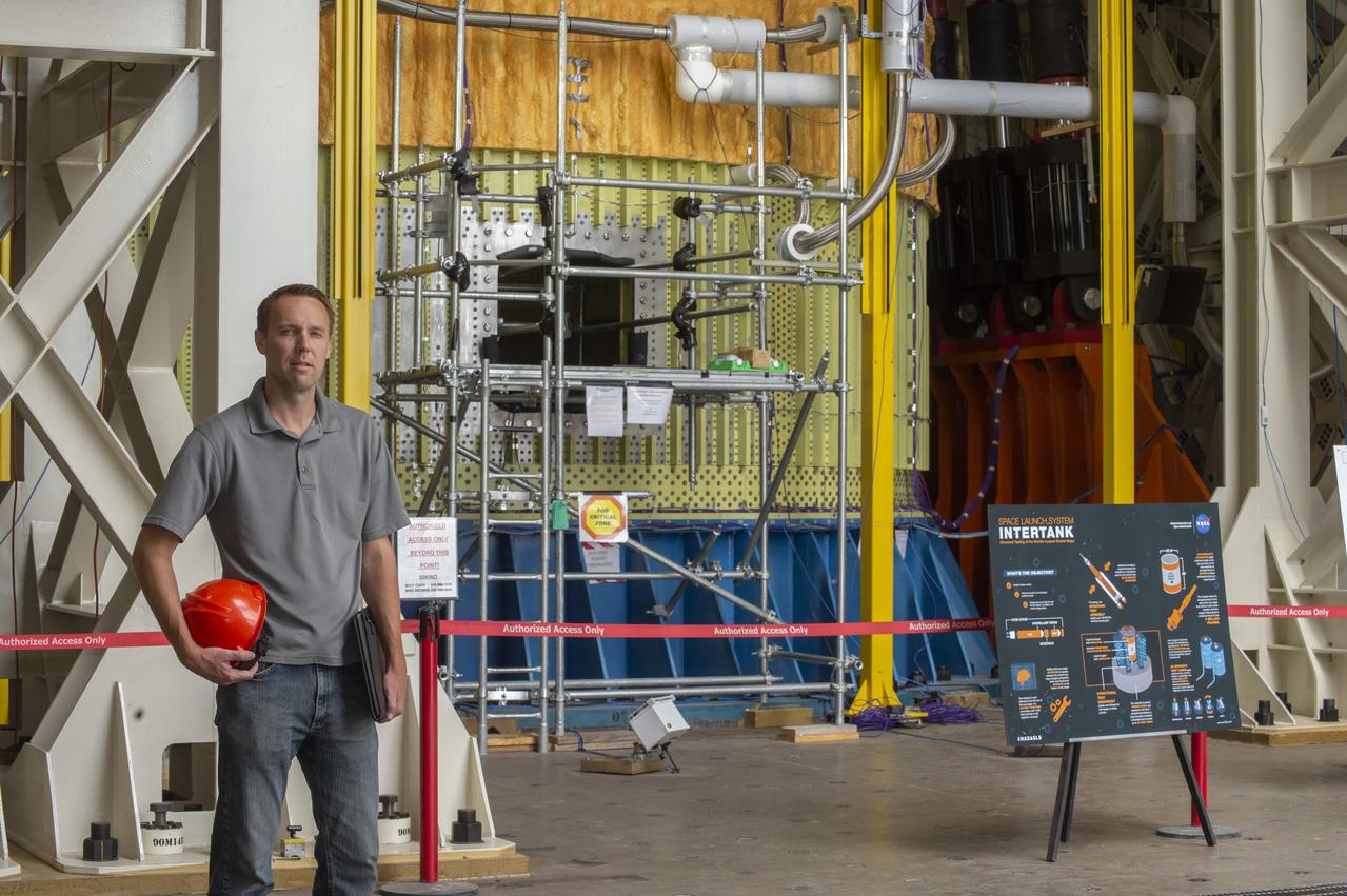
Preston Schmauch, SLS Stages Element Alternate Lead Systems Engineer, oversees testing of the Intertank Structural Test Article (STA), which will push, pull, and bend the STA with millions of pounds of force to prove the SLS Intertank can withstand the immense forces induced by aero, engine, and booster loads during flight.
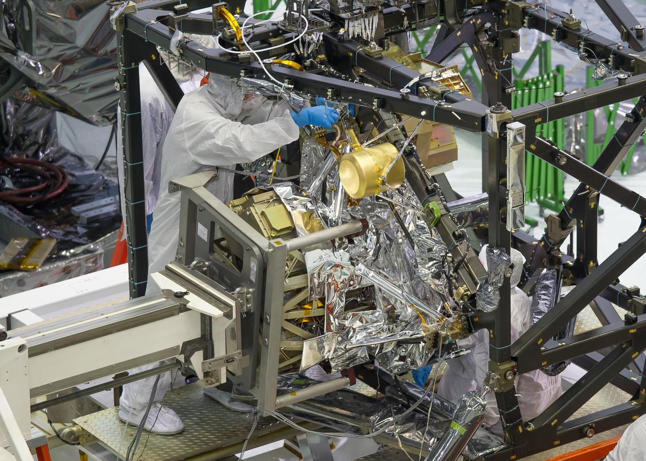
A technician is installing the bolts that will hold the MIRI, or Mid-Infrared Instrument, to the composite Integrated Science Instrument Module (ISIM) structure, or the black frame. The MIRI is attached to a balance beam, called the Horizontal Integration Tool (HIT), hanging from a precision overhead crane. That's the same tool that Hubble engineers used to prepare hardware for its servicing missions. Photo Credit: NASA/Chris Gunn; Text Credit: NASA/Laura Betz ---- Engineers worked meticulously to implant the James Webb Space Telescope's Mid-Infrared Instrument into the ISIM, or Integrated Science Instrument Module, in the cleanroom at NASA's Goddard Space Flight Center in Greenbelt, Md. As the successor to NASA's Hubble Space Telescope, the Webb telescope will be the most powerful space telescope ever built. It will observe the most distant objects in the universe, provide images of the first galaxies formed and see unexplored planets around distant stars. For more information, visit: <a href="http://www.jwst.nasa.gov" rel="nofollow">www.jwst.nasa.gov</a> <b><a href="http://www.nasa.gov/audience/formedia/features/MP_Photo_Guidelines.html" rel="nofollow">NASA image use policy.</a></b> <b><a href="http://www.nasa.gov/centers/goddard/home/index.html" rel="nofollow">NASA Goddard Space Flight Center</a></b> enables NASA’s mission through four scientific endeavors: Earth Science, Heliophysics, Solar System Exploration, and Astrophysics. Goddard plays a leading role in NASA’s accomplishments by contributing compelling scientific knowledge to advance the Agency’s mission. <b>Follow us on <a href="http://twitter.com/NASA_GoddardPix" rel="nofollow">Twitter</a></b> <b>Like us on <a href="http://www.facebook.com/pages/Greenbelt-MD/NASA-Goddard/395013845897?ref=tsd" rel="nofollow">Facebook</a></b> <b>Find us on <a href="http://instagram.com/nasagoddard?vm=grid" rel="nofollow">Instagram</a></b>
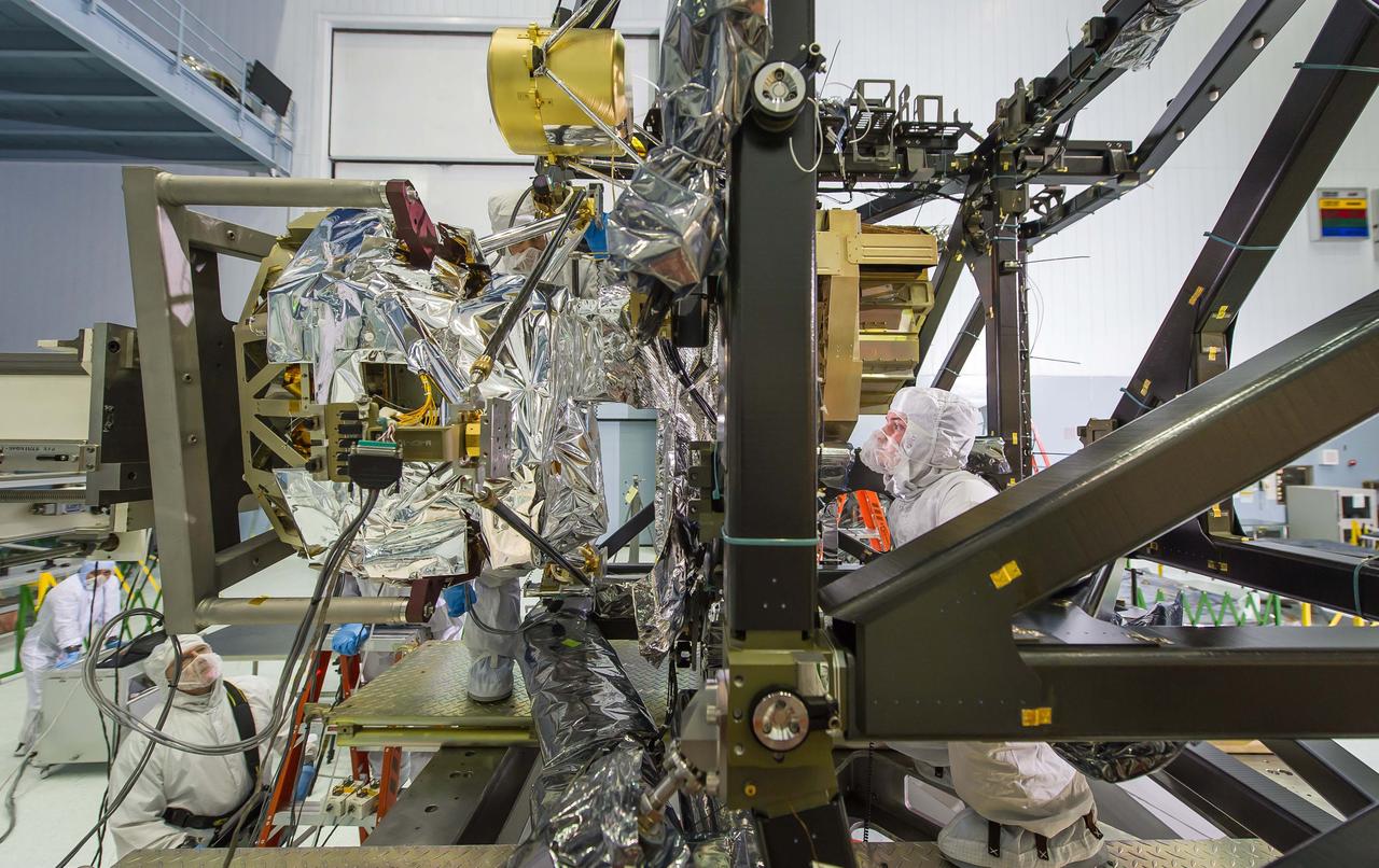
Engineers Tom Huber (behind MIRI) and Mick Wilks (inside black ISIM Structure) check that MIRI is integrated precisely. The engineers have to make sure that MIRI, the only instrument on the Webb telescope that 'sees' mid-infrared light, is precisely positioned so that it and the other instruments can glimpse the formation of galaxies and see deeper into the universe than ever before. Photo Credit: NASA/Chris Gunn; Text Credit: NASA/Laura Betz ---- Engineers worked meticulously to implant the James Webb Space Telescope's Mid-Infrared Instrument into the ISIM, or Integrated Science Instrument Module, in the cleanroom at NASA's Goddard Space Flight Center in Greenbelt, Md. As the successor to NASA's Hubble Space Telescope, the Webb telescope will be the most powerful space telescope ever built. It will observe the most distant objects in the universe, provide images of the first galaxies formed and see unexplored planets around distant stars. For more information, visit: <a href="http://www.jwst.nasa.gov" rel="nofollow">www.jwst.nasa.gov</a> <b><a href="http://www.nasa.gov/audience/formedia/features/MP_Photo_Guidelines.html" rel="nofollow">NASA image use policy.</a></b> <b><a href="http://www.nasa.gov/centers/goddard/home/index.html" rel="nofollow">NASA Goddard Space Flight Center</a></b> enables NASA’s mission through four scientific endeavors: Earth Science, Heliophysics, Solar System Exploration, and Astrophysics. Goddard plays a leading role in NASA’s accomplishments by contributing compelling scientific knowledge to advance the Agency’s mission. <b>Follow us on <a href="http://twitter.com/NASA_GoddardPix" rel="nofollow">Twitter</a></b> <b>Like us on <a href="http://www.facebook.com/pages/Greenbelt-MD/NASA-Goddard/395013845897?ref=tsd" rel="nofollow">Facebook</a></b> <b>Find us on <a href="http://instagram.com/nasagoddard?vm=grid" rel="nofollow">Instagram</a></b>

Engineers are checking to make sure that MIRI is precisely positioned with the ISIM as it slides into position. They have to make sure it's installed exactly where it needs to be within the width of a thin human hair. Visible is MIRI's pickoff mirror, which is the protrusion on the right side of the instrument that looks like a periscope on its side. This is where MIRI grabs light coming from the telescope optics. Also visible is the silver-colored base of MIRI's cryocooled shield, already installed on the ISIM structure and with a hole in it for MIRI's pickoff mirror. MIRI itself has special silver-colored blanketing around it as insulation to keep it at its proper cryogenic temperature during operation. Photo Credit: NASA/Chris Gunn; Text Credit: NASA/Laura Betz ---- Engineers worked meticulously to implant the James Webb Space Telescope's Mid-Infrared Instrument into the ISIM, or Integrated Science Instrument Module, in the cleanroom at NASA's Goddard Space Flight Center in Greenbelt, Md. As the successor to NASA's Hubble Space Telescope, the Webb telescope will be the most powerful space telescope ever built. It will observe the most distant objects in the universe, provide images of the first galaxies formed and see unexplored planets around distant stars. For more information, visit: <a href="http://www.jwst.nasa.gov" rel="nofollow">www.jwst.nasa.gov</a> <b><a href="http://www.nasa.gov/audience/formedia/features/MP_Photo_Guidelines.html" rel="nofollow">NASA image use policy.</a></b> <b><a href="http://www.nasa.gov/centers/goddard/home/index.html" rel="nofollow">NASA Goddard Space Flight Center</a></b> enables NASA’s mission through four scientific endeavors: Earth Science, Heliophysics, Solar System Exploration, and Astrophysics. Goddard plays a leading role in NASA’s accomplishments by contributing compelling scientific knowledge to advance the Agency’s mission. <b>Follow us on <a href="http://twitter.com/NASA_GoddardPix" rel="nofollow">Twitter</a></b> <b>Like us on <a href="http://www.facebook.com/pages/Greenbelt-MD/NASA-Goddard/395013845897?ref=tsd" rel="nofollow">Facebook</a></b> <b>Find us on <a href="http://instagram.com/nasagoddard?vm=grid" rel="nofollow">Instagram</a></b>
iss052e016460 (7/19/2017) --- A view taken of Capillary Structures setup in the Japanese Experiment Module (JEM) beside the internal airlock. This investigation studies a new method using structures of specific shapes to manage fluid and gas mixtures. It also studies water recycling and carbon dioxide removal, benefiting future efforts to design lightweight, more reliable life support systems for future space missions.
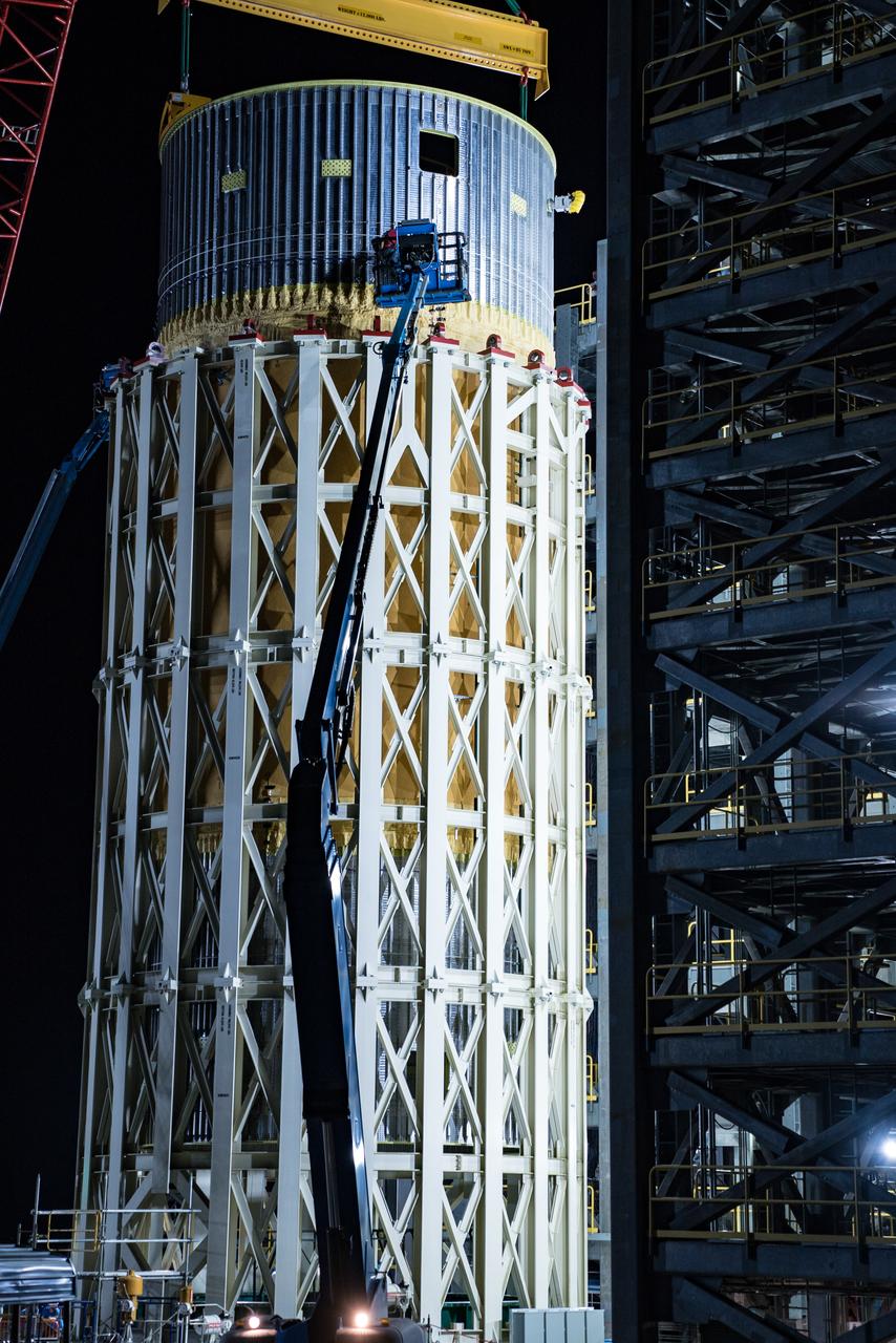
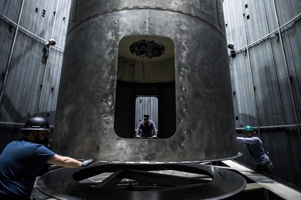
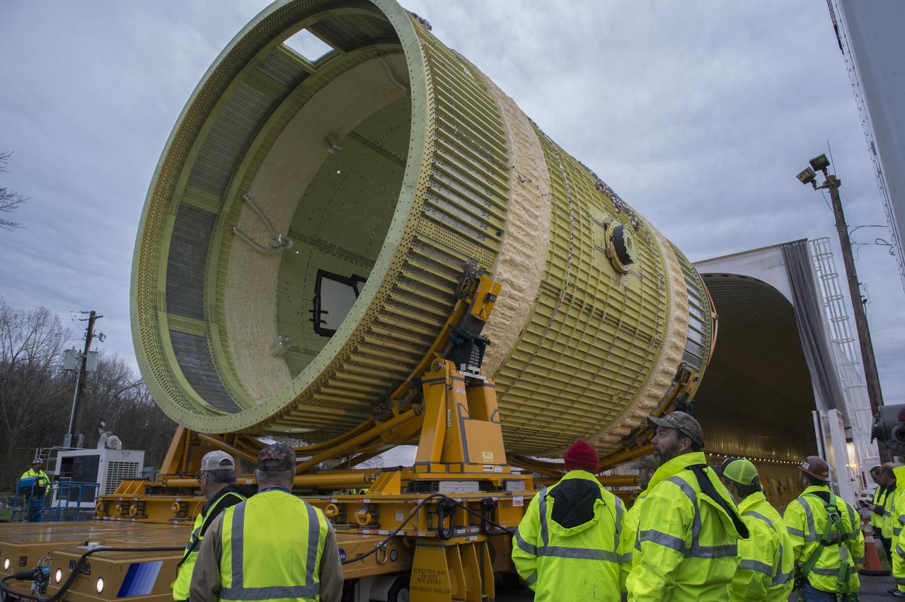
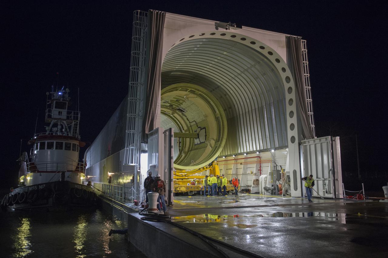
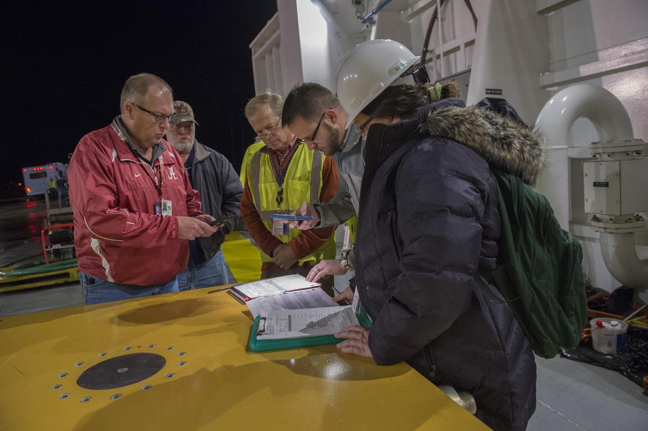
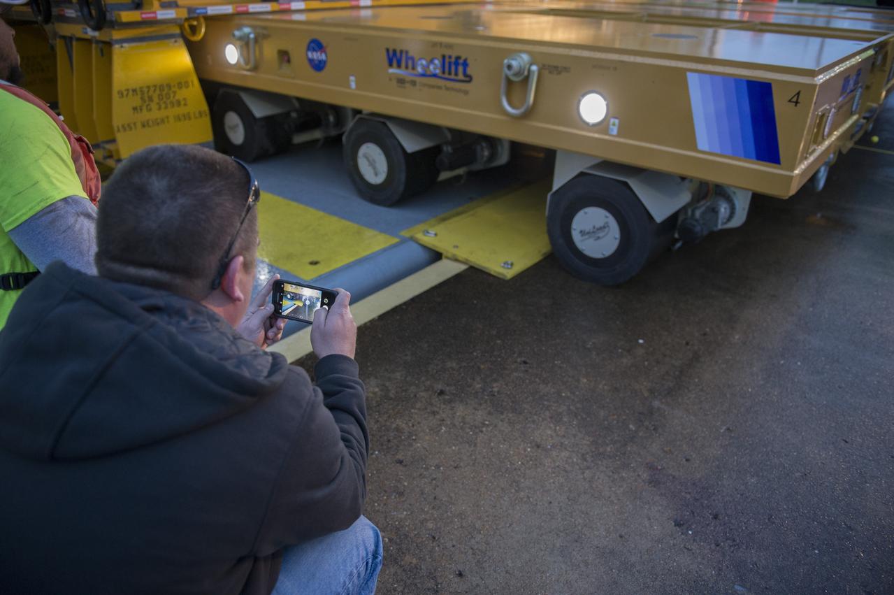
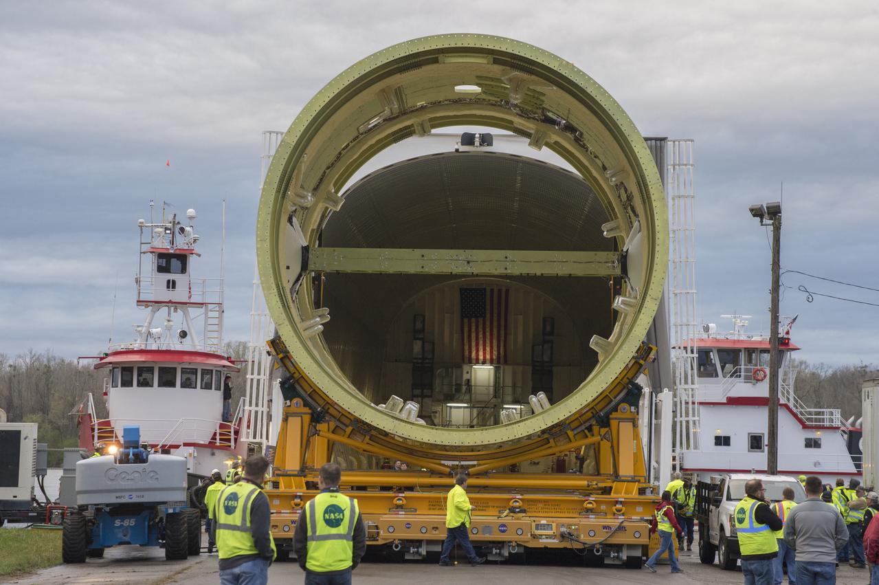
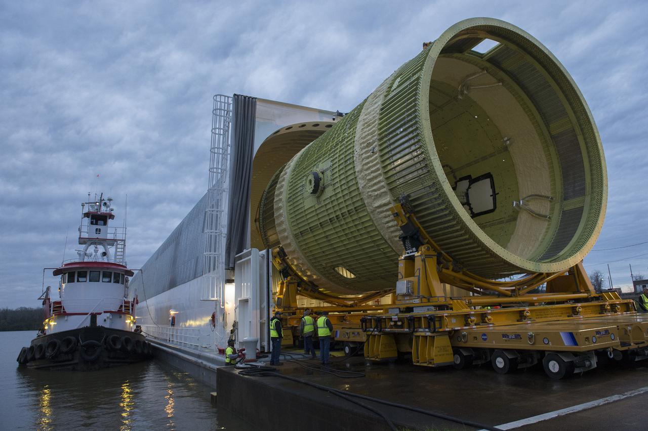
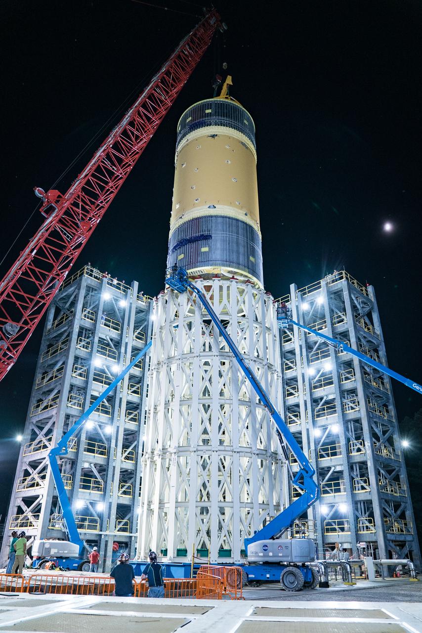
This collection of photos shows the steps NASA engineers took to lift the final structural test article for NASA’s Space Launch System (SLS) core stage into Test Stand 4697 at NASA’s Marshall Space Flight Center in Huntsville, Alabama, July 10, 2019. The liquid oxygen (LOX) tank is one of two propellant tanks in the rocket’s massive core stage that will produce more than 2 million pounds of thrust to help launch Artemis 1, the first flight of NASA’s Orion spacecraft and SLS, to the Moon. The nearly 70-foot-long liquid oxygen tank structural test article was manufactured at NASA’s Michoud Assembly Facility in New Orleans and delivered by NASA’s barge Pegasus to Marshall. Once bolted into the test stand, dozens of hydraulic cylinders will push and pull the tank, subjecting it to the same stresses and forces it will endure during liftoff and flight, to verify it is fit for flight.
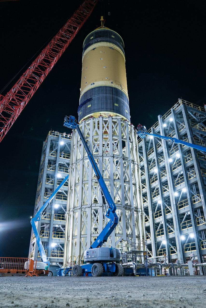
This collection of photos shows the steps NASA engineers took to lift the final structural test article for NASA’s Space Launch System (SLS) core stage into Test Stand 4697 at NASA’s Marshall Space Flight Center in Huntsville, Alabama, July 10, 2019. The liquid oxygen (LOX) tank is one of two propellant tanks in the rocket’s massive core stage that will produce more than 2 million pounds of thrust to help launch Artemis 1, the first flight of NASA’s Orion spacecraft and SLS, to the Moon. The nearly 70-foot-long liquid oxygen tank structural test article was manufactured at NASA’s Michoud Assembly Facility in New Orleans and delivered by NASA’s barge Pegasus to Marshall. Once bolted into the test stand, dozens of hydraulic cylinders will push and pull the tank, subjecting it to the same stresses and forces it will endure during liftoff and flight, to verify it is fit for flight.
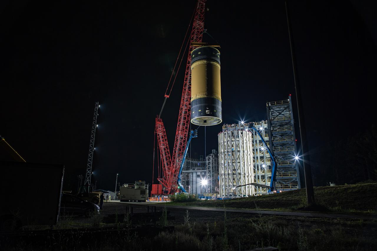
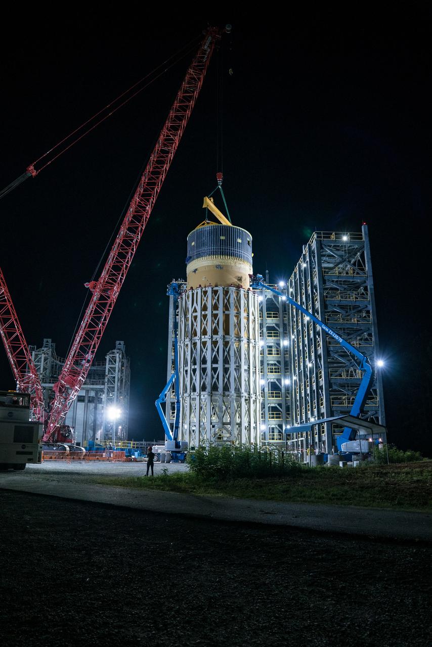
This collection of photos shows the steps NASA engineers took to lift the final structural test article for NASA’s Space Launch System (SLS) core stage into Test Stand 4697 at NASA’s Marshall Space Flight Center in Huntsville, Alabama, July 10, 2019. The liquid oxygen (LOX) tank is one of two propellant tanks in the rocket’s massive core stage that will produce more than 2 million pounds of thrust to help launch Artemis 1, the first flight of NASA’s Orion spacecraft and SLS, to the Moon. The nearly 70-foot-long liquid oxygen tank structural test article was manufactured at NASA’s Michoud Assembly Facility in New Orleans and delivered by NASA’s barge Pegasus to Marshall. Once bolted into the test stand, dozens of hydraulic cylinders will push and pull the tank, subjecting it to the same stresses and forces it will endure during liftoff and flight, to verify it is fit for flight.
This collection of photos shows the steps NASA engineers took to lift the final structural test article for NASA’s Space Launch System (SLS) core stage into Test Stand 4697 at NASA’s Marshall Space Flight Center in Huntsville, Alabama, July 10, 2019. The liquid oxygen (LOX) tank is one of two propellant tanks in the rocket’s massive core stage that will produce more than 2 million pounds of thrust to help launch Artemis 1, the first flight of NASA’s Orion spacecraft and SLS, to the Moon. The nearly 70-foot-long liquid oxygen tank structural test article was manufactured at NASA’s Michoud Assembly Facility in New Orleans and delivered by NASA’s barge Pegasus to Marshall. Once bolted into the test stand, dozens of hydraulic cylinders will push and pull the tank, subjecting it to the same stresses and forces it will endure during liftoff and flight, to verify it is fit for flight.
This collection of photos shows the steps NASA engineers took to lift the final structural test article for NASA’s Space Launch System (SLS) core stage into Test Stand 4697 at NASA’s Marshall Space Flight Center in Huntsville, Alabama, July 10, 2019. The liquid oxygen (LOX) tank is one of two propellant tanks in the rocket’s massive core stage that will produce more than 2 million pounds of thrust to help launch Artemis 1, the first flight of NASA’s Orion spacecraft and SLS, to the Moon. The nearly 70-foot-long liquid oxygen tank structural test article was manufactured at NASA’s Michoud Assembly Facility in New Orleans and delivered by NASA’s barge Pegasus to Marshall. Once bolted into the test stand, dozens of hydraulic cylinders will push and pull the tank, subjecting it to the same stresses and forces it will endure during liftoff and flight, to verify it is fit for flight.
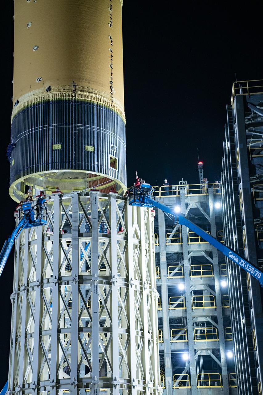
This collection of photos shows the steps NASA engineers took to lift the final structural test article for NASA’s Space Launch System (SLS) core stage into Test Stand 4697 at NASA’s Marshall Space Flight Center in Huntsville, Alabama, July 10, 2019. The liquid oxygen (LOX) tank is one of two propellant tanks in the rocket’s massive core stage that will produce more than 2 million pounds of thrust to help launch Artemis 1, the first flight of NASA’s Orion spacecraft and SLS, to the Moon. The nearly 70-foot-long liquid oxygen tank structural test article was manufactured at NASA’s Michoud Assembly Facility in New Orleans and delivered by NASA’s barge Pegasus to Marshall. Once bolted into the test stand, dozens of hydraulic cylinders will push and pull the tank, subjecting it to the same stresses and forces it will endure during liftoff and flight, to verify it is fit for flight.
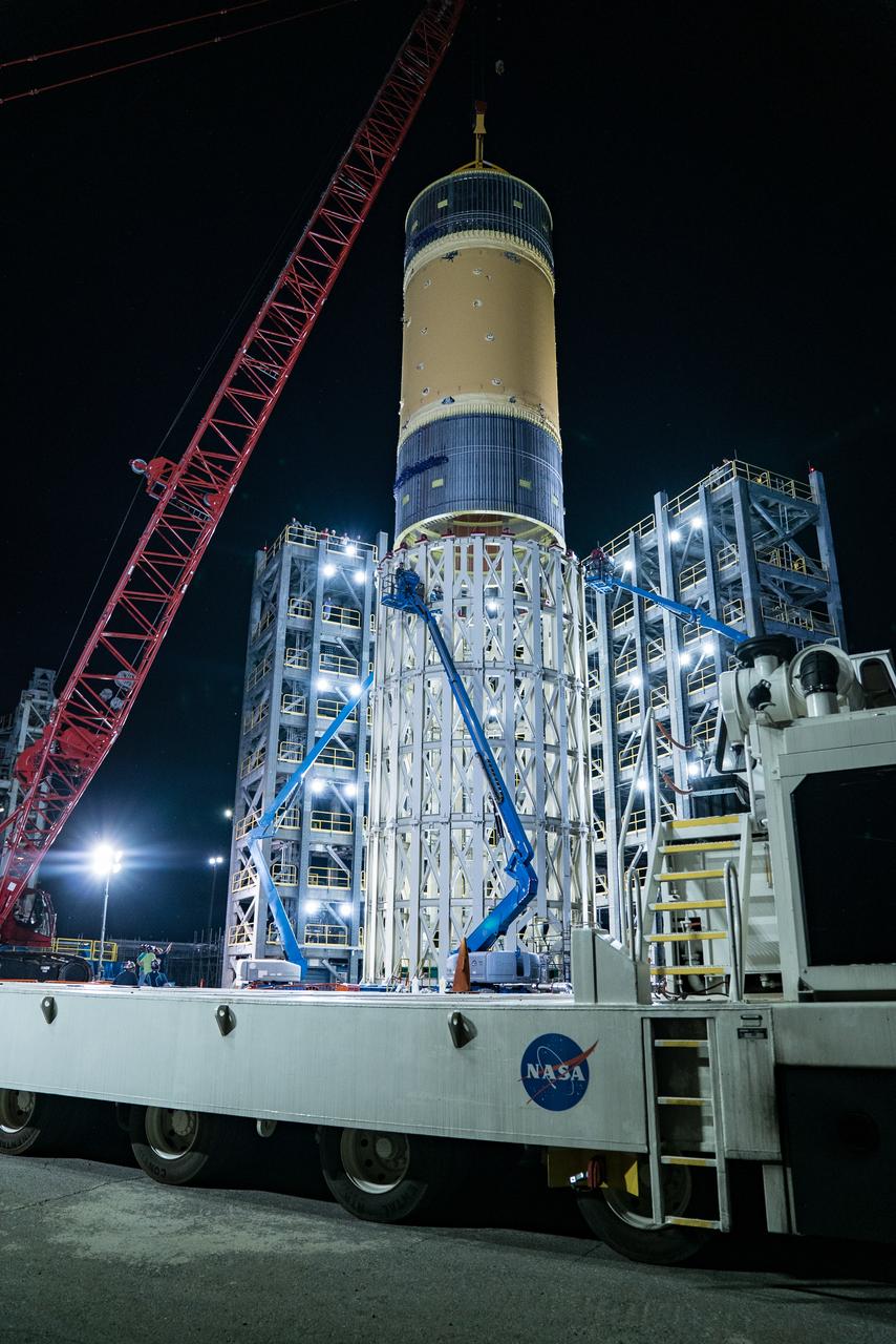
This collection of photos shows the steps NASA engineers took to lift the final structural test article for NASA’s Space Launch System (SLS) core stage into Test Stand 4697 at NASA’s Marshall Space Flight Center in Huntsville, Alabama, July 10, 2019. The liquid oxygen (LOX) tank is one of two propellant tanks in the rocket’s massive core stage that will produce more than 2 million pounds of thrust to help launch Artemis 1, the first flight of NASA’s Orion spacecraft and SLS, to the Moon. The nearly 70-foot-long liquid oxygen tank structural test article was manufactured at NASA’s Michoud Assembly Facility in New Orleans and delivered by NASA’s barge Pegasus to Marshall. Once bolted into the test stand, dozens of hydraulic cylinders will push and pull the tank, subjecting it to the same stresses and forces it will endure during liftoff and flight, to verify it is fit for flight.