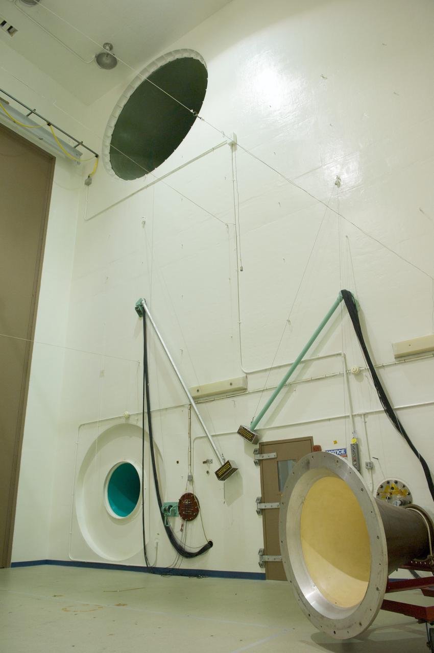
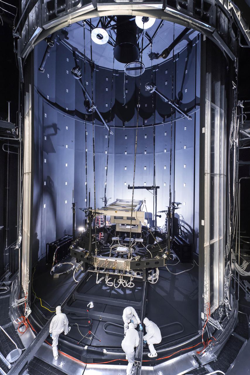
At Goddard, the engineers use the Acoustic Test Chamber, a 42-foot-tall chamber, with 6-foot-diameter speaker horns to replicate the launch environment. The horns use an altering flow of gaseous nitrogen to produce a sound level as high as 150 decibels for two-minute tests. That’s about the level of sound heard standing next to a jet engine during takeoff. The 6-foot-wide horns in this 42-foot-tall chamber can produce noise at levels as high as 150 dB. During the acoustics test, the speakers can still be heard outside of its insulated massive metal doors. Credits: NASA/Goddard/Chris Gunn <b><a href="http://www.nasa.gov/audience/formedia/features/MP_Photo_Guidelines.html" rel="nofollow">NASA image use policy.</a></b> <b><a href="http://www.nasa.gov/centers/goddard/home/index.html" rel="nofollow">NASA Goddard Space Flight Center</a></b> enables NASA’s mission through four scientific endeavors: Earth Science, Heliophysics, Solar System Exploration, and Astrophysics. Goddard plays a leading role in NASA’s accomplishments by contributing compelling scientific knowledge to advance the Agency’s mission. <b>Follow us on <a href="http://twitter.com/NASAGoddardPix" rel="nofollow">Twitter</a></b> <b>Like us on <a href="http://www.facebook.com/pages/Greenbelt-MD/NASA-Goddard/395013845897?ref=tsd" rel="nofollow">Facebook</a></b> <b>Find us on <a href="http://instagrid.me/nasagoddard/?vm=grid" rel="nofollow">Instagram</a></b>
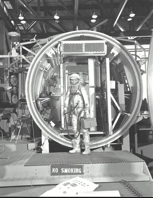
M61-00150 (1961) --- Astronaut John H. Glenn Jr., suited with hose to suit ventilation unit attached, during altitude chamber test. He is standing in the entrance to the test chamber with his helmet visor down. Photo credit: NASA
The vacuum chamber at NASA Jet Propulsion Laboratory in Pasadena, California, used for testing WFIRST and other coronagraphs.
The Mid-Infrared Instrument, a component of NASA James Webb Space Telescope, underwent testing inside the thermal space test chamber at the Science and Technology Facilities Council Rutherford Appleton Laboratory Space in Oxfordshire, England.
The test chamber is 38 ft in diameter by 62 ft deep amd made of stainless steel. It is vacuum rated at 10-7 torr long duration (Local atmospheric pressure to 100 statute miles altitude). The vacuum chamber surfaces are lined with a liquid nitrogen cold wall, capable of maintaining -320 °F. A quartz infrared heating system can be programmed to radiate a sinusoidal distribution, simulating rotational solar heating. Photo Credit: (NASA/Quentin Schwinn)
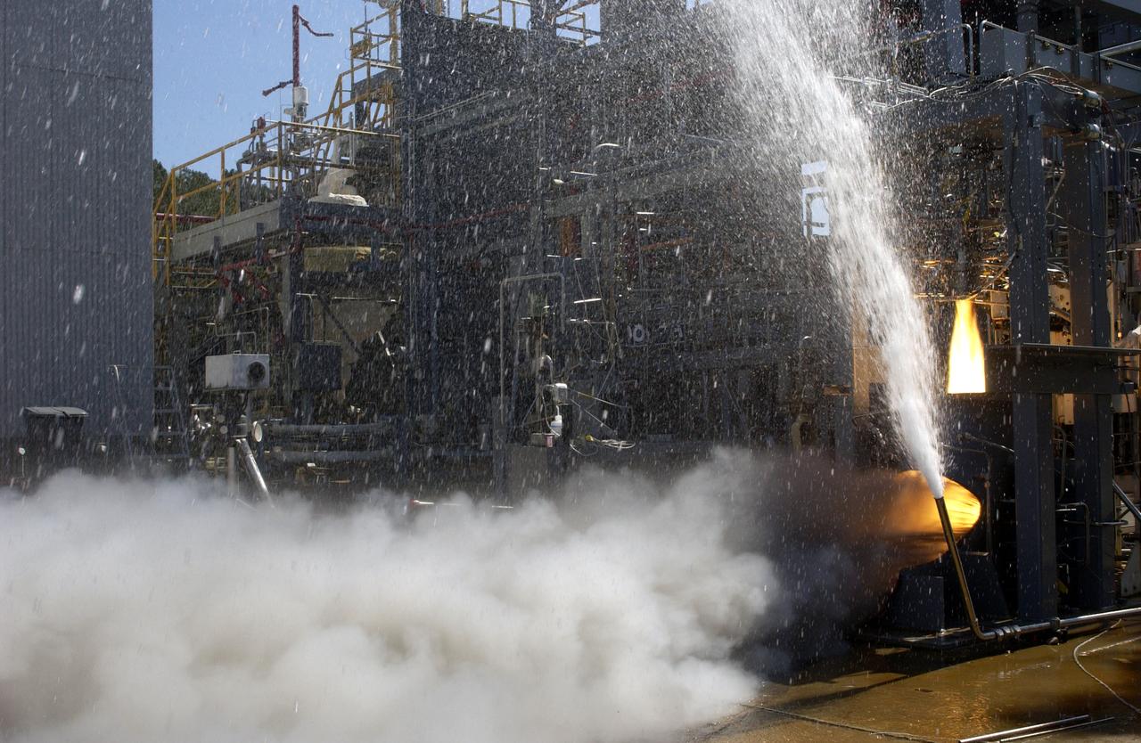
This photograph depicts one of over thirty tests conducted on the Vortex Combustion Chamber Engine at Marshall Space Flight Center's (MSFC) test stand 115, a joint effort between NASA's MSFC and the U.S. Army AMCOM of Redstone Arsenal. The engine tests were conducted to evaluate an irnovative, "self-cooled", vortex combustion chamber, which relies on tangentially injected propellants from the chamber wall producing centrifugal forces that keep the relatively cold liquid propellants near the wall.
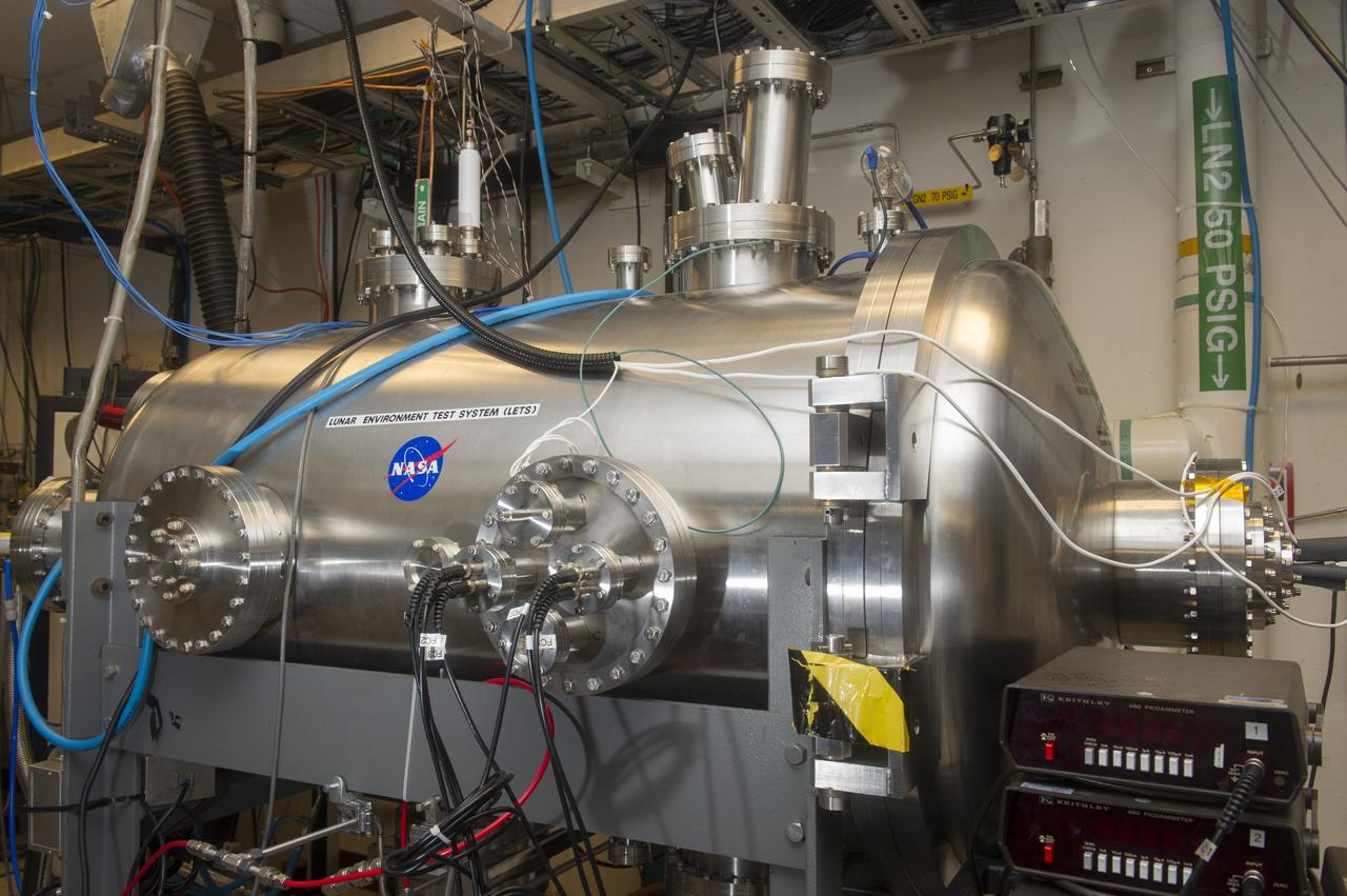
BLDG 4605, LUNAR ENVIRONMENTS TEST SYSTEM VACUUM CHAMBER, EAST SIDE
BLDG 4605, LUNAR ENVIRONMENTS TEST SYSTEM VACUUM CHAMBER, WEST SIDE
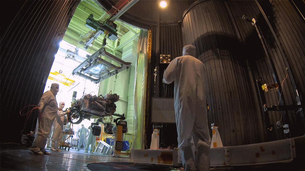
This photo was captured from outside the enormous mouth of NASA's giant thermal vacuum chamber, called Chamber A, at Johnson Space Center in Houston. Previously used for manned spaceflight missions, this historic chamber is now filled with engineers and technicians preparing a lift system that will be used to hold the James Webb Space Telescope during testing. The James Webb Space Telescope is the scientific successor to NASA's Hubble Space Telescope. It will be the most powerful space telescope ever built. Webb is an international project led by NASA with its partners, the European Space Agency and the Canadian Space Agency. Credit: NASA/Goddard/Chris Gunn <b><a href="http://www.nasa.gov/audience/formedia/features/MP_Photo_Guidelines.html" rel="nofollow">NASA image use policy.</a></b> <b><a href="http://www.nasa.gov/centers/goddard/home/index.html" rel="nofollow">NASA Goddard Space Flight Center</a></b> enables NASA’s mission through four scientific endeavors: Earth Science, Heliophysics, Solar System Exploration, and Astrophysics. Goddard plays a leading role in NASA’s accomplishments by contributing compelling scientific knowledge to advance the Agency’s mission. <b>Follow us on <a href="http://twitter.com/NASAGoddardPix" rel="nofollow">Twitter</a></b> <b>Like us on <a href="http://www.facebook.com/pages/Greenbelt-MD/NASA-Goddard/395013845897?ref=tsd" rel="nofollow">Facebook</a></b> <b>Find us on <a href="http://instagrid.me/nasagoddard/?vm=grid" rel="nofollow">Instagram</a></b>

An engineer prepares the Carbon Mapper imaging spectrometer, which will measure the greenhouse gases methane and carbon dioxide from space, for testing in a thermal vacuum chamber at NASA's Jet Propulsion Laboratory in Southern California in July 2023. This test is one of a series meant to ensure that the instrument can withstand the rigors of launch and the harsh conditions of space. Engineers used the chamber to subject the spectrometer to the extreme temperatures it will encounter in the vacuum of space. The instrument was shipped from JPL to Planet Labs PBC in San Francisco on Sept. 12, 2023, where it will be integrated into a Tanager satellite. Designed and built by JPL, imaging spectrometer will be part of an effort led by the nonprofit Carbon Mapper organization to collect data on greenhouse gas point-source emissions. The information will help locate and quantify "super-emitters" – the small percentage of individual sources responsible for a significant fraction of methane and carbon dioxide emissions around the world. https://photojournal.jpl.nasa.gov/catalog/PIA26094
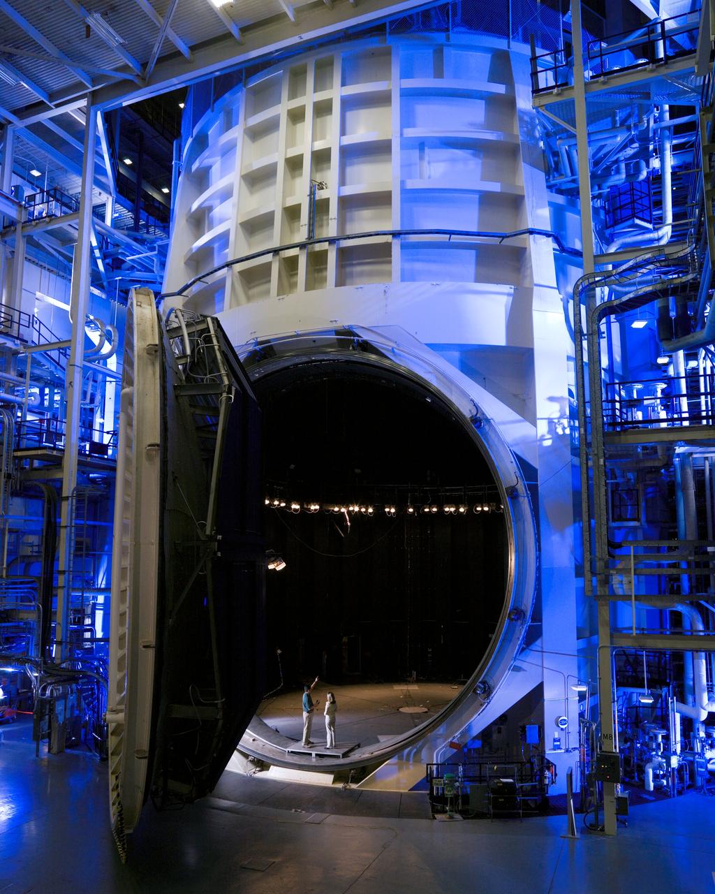
View of Thermal Vacuum Test Chamber A (with it's door opened) in bldg 32. Two people are standing inside the hatch to show a size comparision.
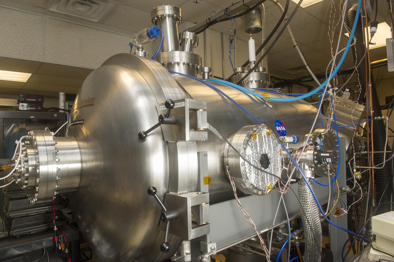
BLDG. 4605 PLASMA ENVIRONMENT TEST LABORATORY. VACUUM CHAMBER FROM REAR
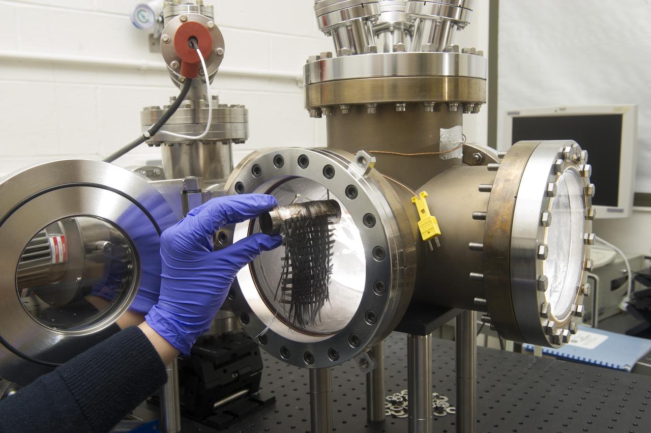
BLDG. 4605 PLASMA ENVIRONMENT TEST LABORATORY. VACUUM CHAMBER OPEN WITH SAMPLE SETUP
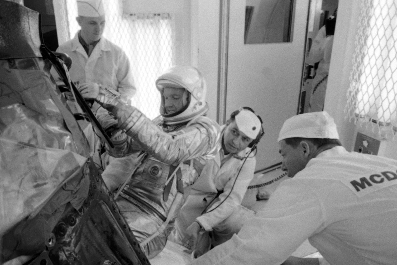
S63-03957 (1963) --- NASA and McDonnell Aircraft Corp. spacecraft technicians assist astronaut L. Gordon Cooper Jr. into his spacecraft prior to undergoing tests in the altitude chamber. These tests are used to determine the operating characteristcs of the overall environmental control system. Photo credit: NASA
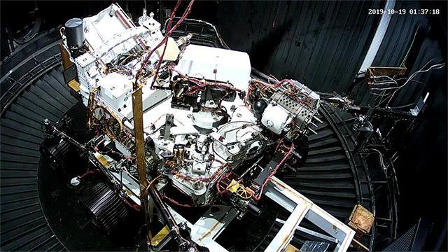
This image, taken on Oct. 9, 2019, at NASA's Jet Propulsion Laboratory in Pasadena, California, captures the move of the Mars 2020 rover into a large vacuum chamber for testing in Mars-like environmental conditions. Movie available at https://photojournal.jpl.nasa.gov/catalog/PIA23470
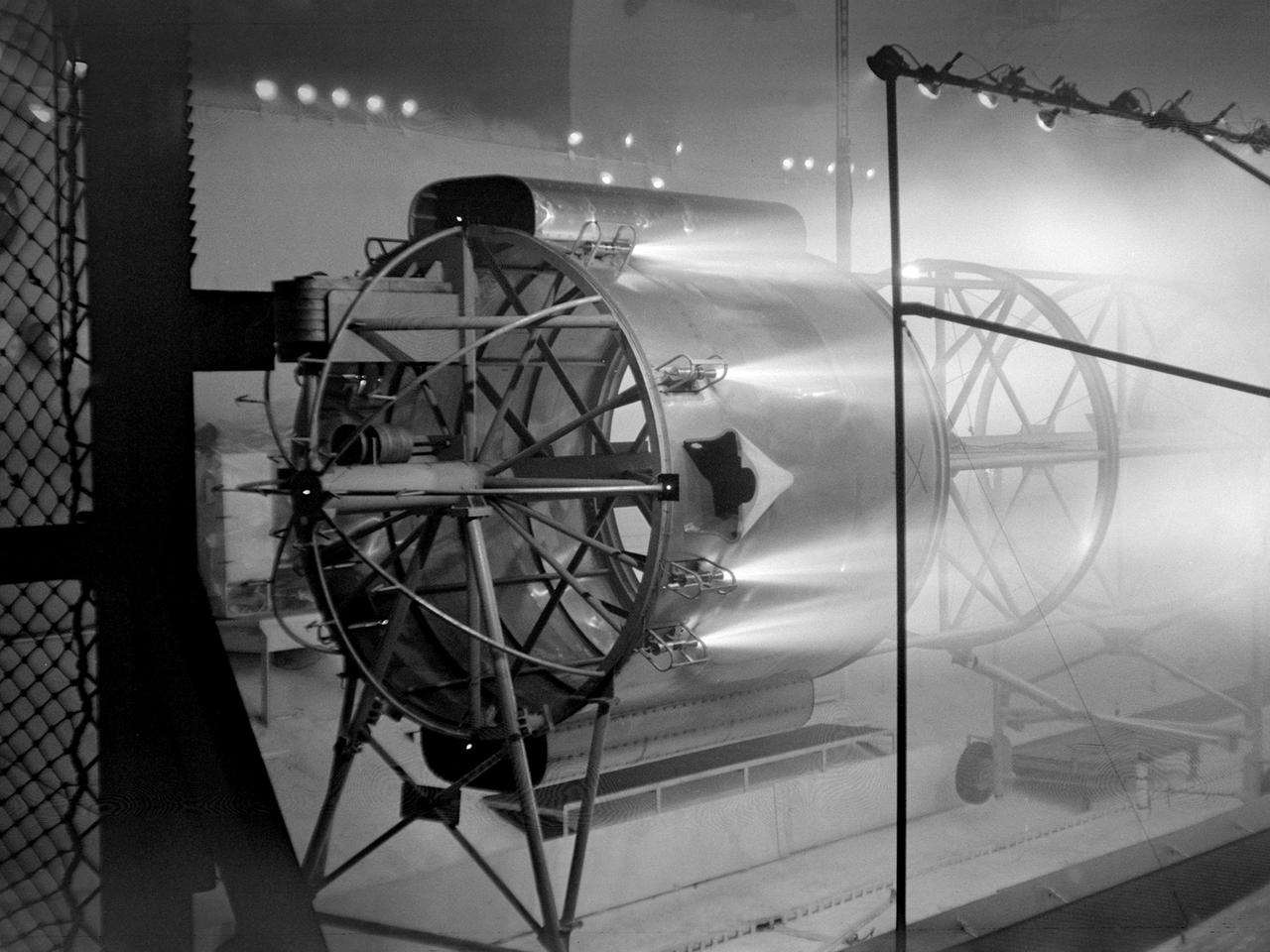
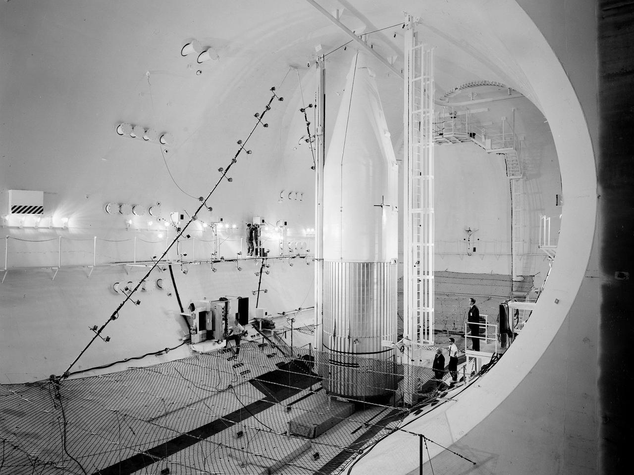
An Atlas/Centaur mass model undergoes a separation test inside the Space Power Chambers at NASA Lewis Research Center. Lewis was in the midst of an extensive effort to prepare the Centaur second-stage rocket for its missions to send the Surveyor spacecraft to the moon as a precursor to the Apollo missions. As part of these preparations, Lewis management decided to convert its Altitude Wind Tunnel into two large test chambers—the Space Power Chambers. The conversion included the removal of the tunnel’s internal components and the insertion of bulkheads to seal off the new chambers within the tunnel. One chamber could simulate conditions found at 100 miles altitude, while this larger chamber simulated the upper atmosphere. In this test series, researchers wanted to verify that the vehicle’s retrorockets would properly separate the Centaur from the Atlas. The model was suspended horizontally on a trolley system inside chamber. A net was hung at one end to catch the jettisoned Atlas model. The chamber atmosphere was reduced to a pressure altitude of 100,000 feet, and high-speed cameras were synchronized to the ignition of the retrorockets. The simulated Centaur is seen here jettisoning from the Atlas out of view to the right. The study resulted in a new jettison method that would significantly reduce the separation time and thus minimize the danger of collision between the two stages during separation.
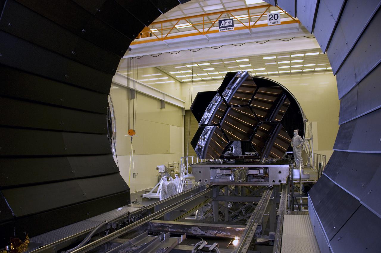
SIX MIRROR SEGMENTS OF THE JAMES WEBB SPACE TELESCOPE ARE REMOVED FROM THE CRYOGENIC TEST CHAMBER

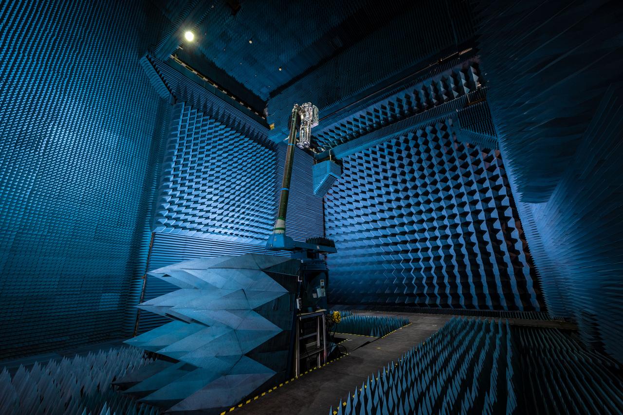
jsc2021e022515 (June 11, 2021) --- NASA’s Exploration Extravehicular Mobility Unit (xEMU) spacesuit undergoes antenna testing in NASA Johnson Space Center’s anechoic chamber to inspect multi-layer insulation keep-out zones for the Wi-Fi and ultra-high-frequency antennas that are part of the spacesuit’s communication system. The xEMU test article is named xGUS, the successor to the Extravehicular Mobility Unit test article (also named GUS), which was named after NASA astronaut Gus Grissom and his iconic silver spacesuit. This image was taken from where the "horn," or source antenna, is located that sends out radio frequency signals to the spacesuit. The anechoic chamber walls are covered with a material that absorbs electromagnetic energy allowing the anechoic chamber to simulate a space environment. The antenna test facility is utilized to test antenna radiation distribution pattern performance for spaceflight applications in electromagnetic environments. Pictured in the photo is antenna test engineer Will Bond.

jsc2021e022488 (June 11, 2021) --- NASA’s Exploration Extravehicular Mobility Unit (xEMU) spacesuit undergoes antenna testing in NASA Johnson Space Center’s anechoic chamber to inspect multi-layer insulation keep-out zones for the Wi-Fi and ultra-high-frequency antennas that are part of the spacesuit’s communication system. The xEMU test article is named xGUS, the successor to the Extravehicular Mobility Unit test article (also named GUS), which was named after NASA astronaut Gus Grissom and his iconic silver spacesuit. This image was taken from where the "horn," or source antenna, is located that sends out radio frequency signals to the spacesuit. The anechoic chamber walls are covered with a material that absorbs electromagnetic energy allowing the anechoic chamber to simulate a space environment. The antenna test facility is utilized to test antenna radiation distribution pattern performance for spaceflight applications in electromagnetic environments. Pictured in the photo is antenna test engineer Will Bond.
jsc2021e022487 (June 11, 2021) --- NASA’s Exploration Extravehicular Mobility Unit (xEMU) spacesuit undergoes antenna testing in NASA Johnson Space Center’s anechoic chamber to inspect multi-layer insulation keep-out zones for the Wi-Fi and ultra-high-frequency antennas that are part of the spacesuit’s communication system. The xEMU test article is named xGUS, the successor to the Extravehicular Mobility Unit test article (also named GUS), which was named after NASA astronaut Gus Grissom and his iconic silver spacesuit. This image was taken from where the "horn," or source antenna, is located that sends out radio frequency signals to the spacesuit. The anechoic chamber walls are covered with a material that absorbs electromagnetic energy allowing the anechoic chamber to simulate a space environment. The antenna test facility is utilized to test antenna radiation distribution pattern performance for spaceflight applications in electromagnetic environments.
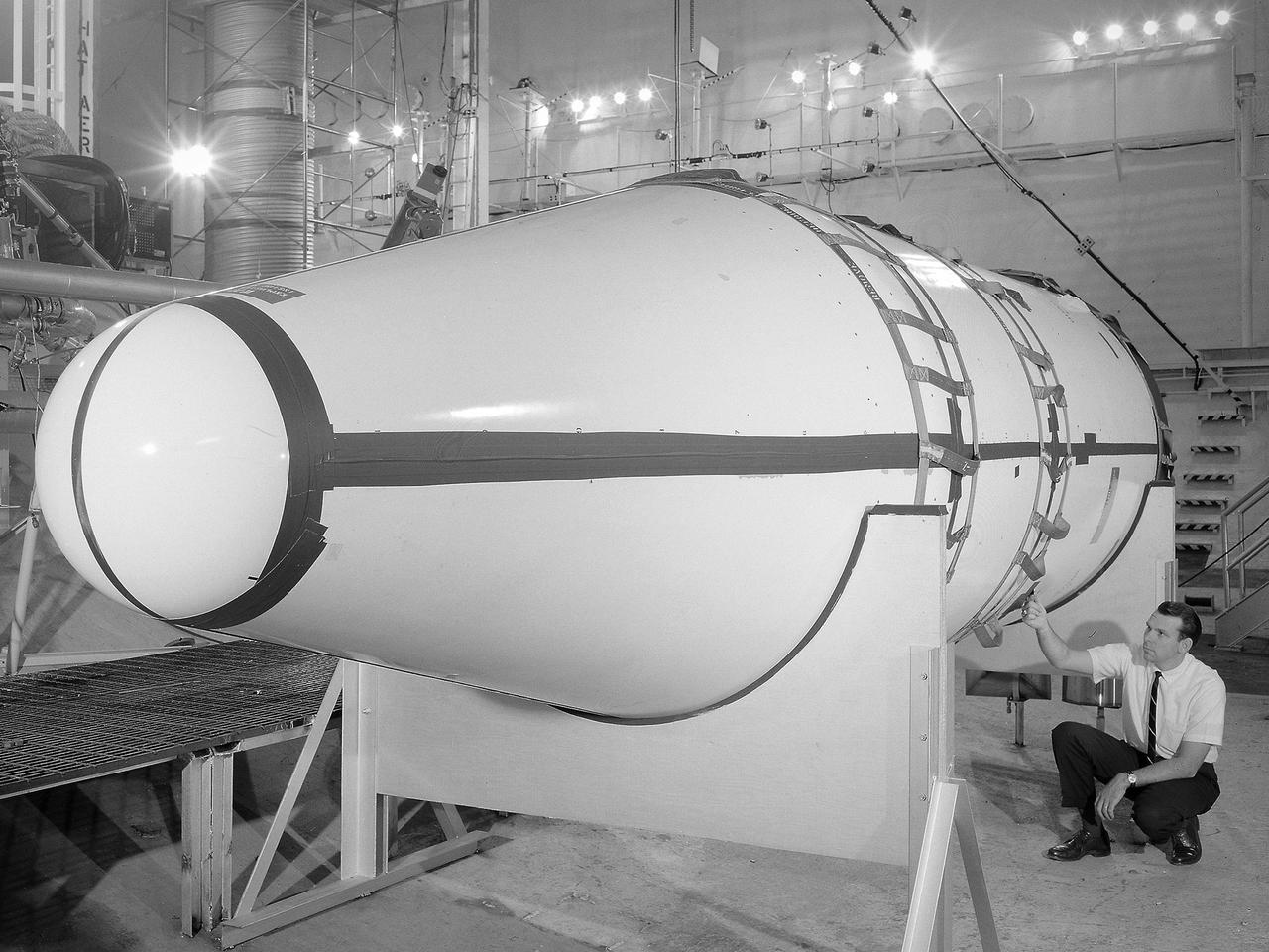
Setup of a Surveyor/Atlas/Centaur shroud in the Space Power Chambers for a leak test at the National Aeronautics and Space Administration (NASA) Lewis Research Center. Centaur was a 15,000-pound thrust second-stage rocket designed for the military in 1957 and 1958 by General Dynamics. It was the first major rocket to use the liquid hydrogen technology developed by Lewis in the 1950s. The Centaur Program suffered numerous problems before being transferred to Lewis in 1962. Several test facilities at Lewis’ main campus and Plum Brook Station were built or modified specifically for Centaur, including the Space Power Chambers. In 1961, NASA Lewis management decided to convert its Altitude Wind Tunnel into two large test chambers and later renamed it the Space Power Chambers. The conversion, which took over 2 years, included the removal of the tunnel’s internal components and insertion of bulkheads to seal off the new chambers. The larger chamber, seen here, could simulate altitudes of 100,000 feet. It was used for Centaur shroud separation and propellant management studies until the early 1970s. The leak test in this photograph was likely an attempt to verify that the shroud’s honeycomb shell did not seep any of its internal air when the chamber was evacuated to pressures similar to those found in the upper atmosphere.
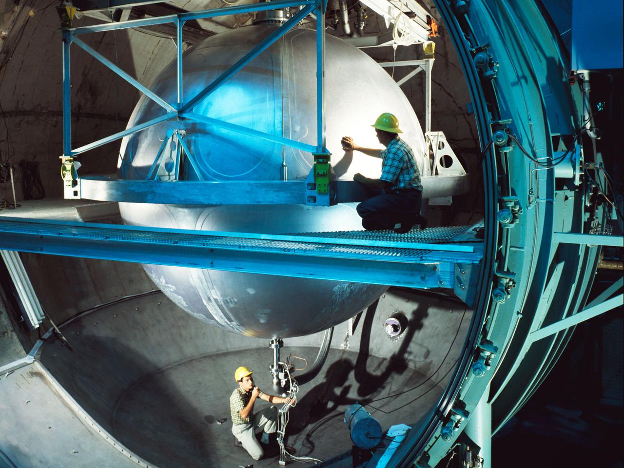
A 13-foot diameter mounted inside the large test chamber at the Cryogenic Propellant Tank, or K-Site, at National Aeronautics and Space Administration’s (NASA) Plum Brook Station. The 25-foot test chamber and 20-foot access door were designed to test liquid hydrogen fuel tanks up to 18 feet in diameter in conditions that simulated launches and spaceflight. Shakers were installed to test the effects of launch vibration on the tanks and their insulation. The K Site chamber was also equipped with cold walls that could be cooled with either liquid nitrogen or liquid hydrogen and vacuum pumps that could reduce pressure levels to 10-8 torr. This 13-foot tank passed its initial acceptance tests in K-Site on August 24, 1966. Delays in the modification of the tank postponed further tests of the tank until May 1967. Four pressure hold tests and expulsion runs were made in May using gaseous hydrogen or gaseous helium at 300R and 520R. In June a straight pipe injector test was run and two pressure effect tests at 35 and 75psi. Propellant slosh tests were successfully run in August. This photograph was taken the day after the program’s final runs on September 12, 1967.
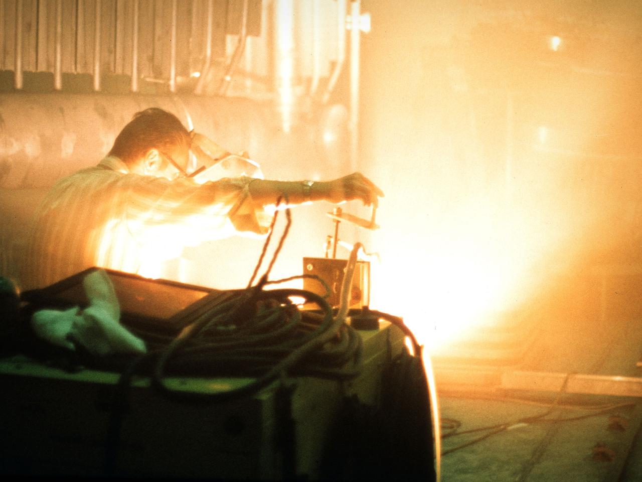
A researcher sets up equipment in the Space Power Chamber at National Aeronautics and Space Administration’s (NASA) Plum Brook Station to study the effects of contaminants on clouds. Drs. Rosa and Jorge Pena of Pennsylvania State University's Department of Meteorology initiated the program in an effort to develop methods of creating stable, long-lasting clouds in a test chamber in order to study their composition and formation. The researchers then wanted to use the artificially-created clouds to determine how they were affected by pollution. The 100-foot diameter and 122-foot high Space Power Chamber is the largest vacuum chamber in the world. The researchers covered the circular walls with muslin. A recirculating water system saturated the cloth. The facility engineers then reduced the chamber’s pressure which released the water from the muslin and generated a cloud. The researchers produced five different clouds in this first portion of this study. They discovered that they could not create stable clouds because of the heat generated by the water-pumping equipment. Nonetheless, they felt confident enough to commence planning the second phase of the program using a heat exchanger to cool the equipment.
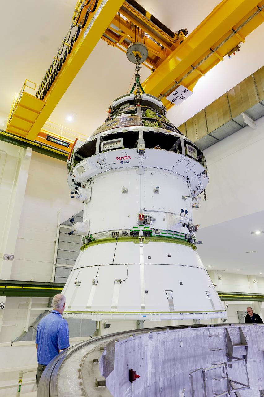
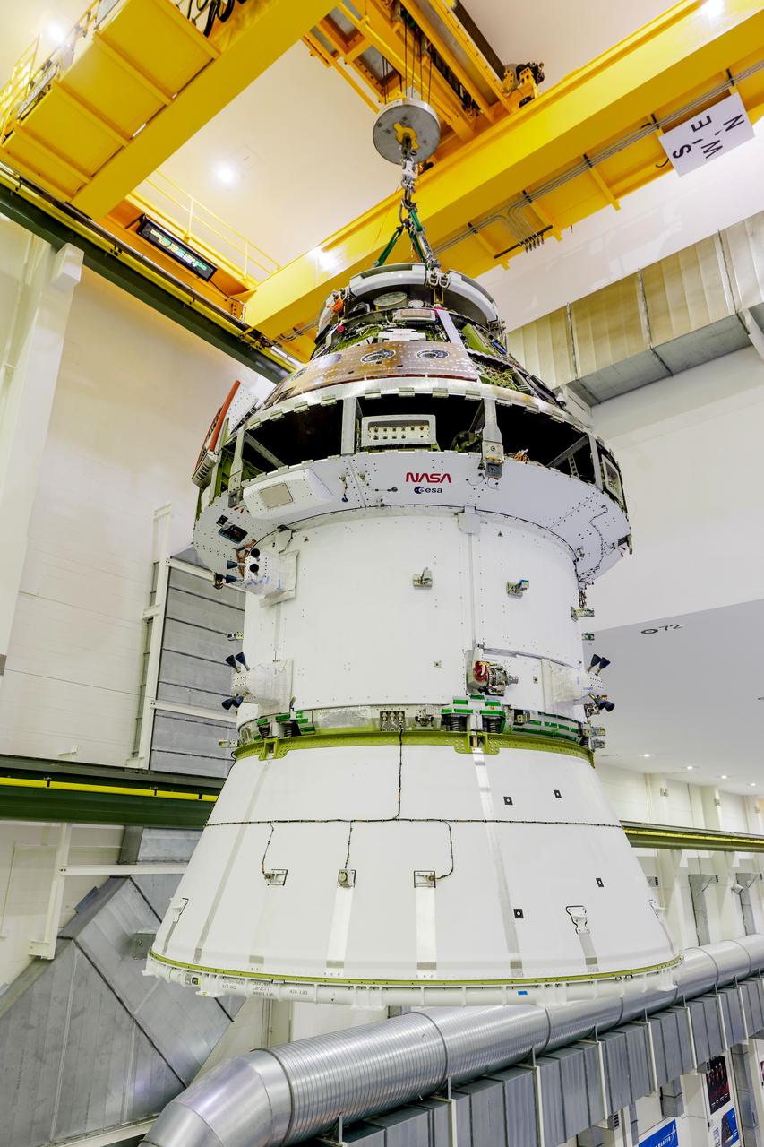
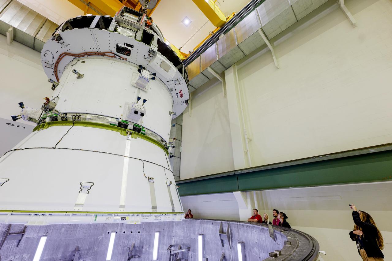
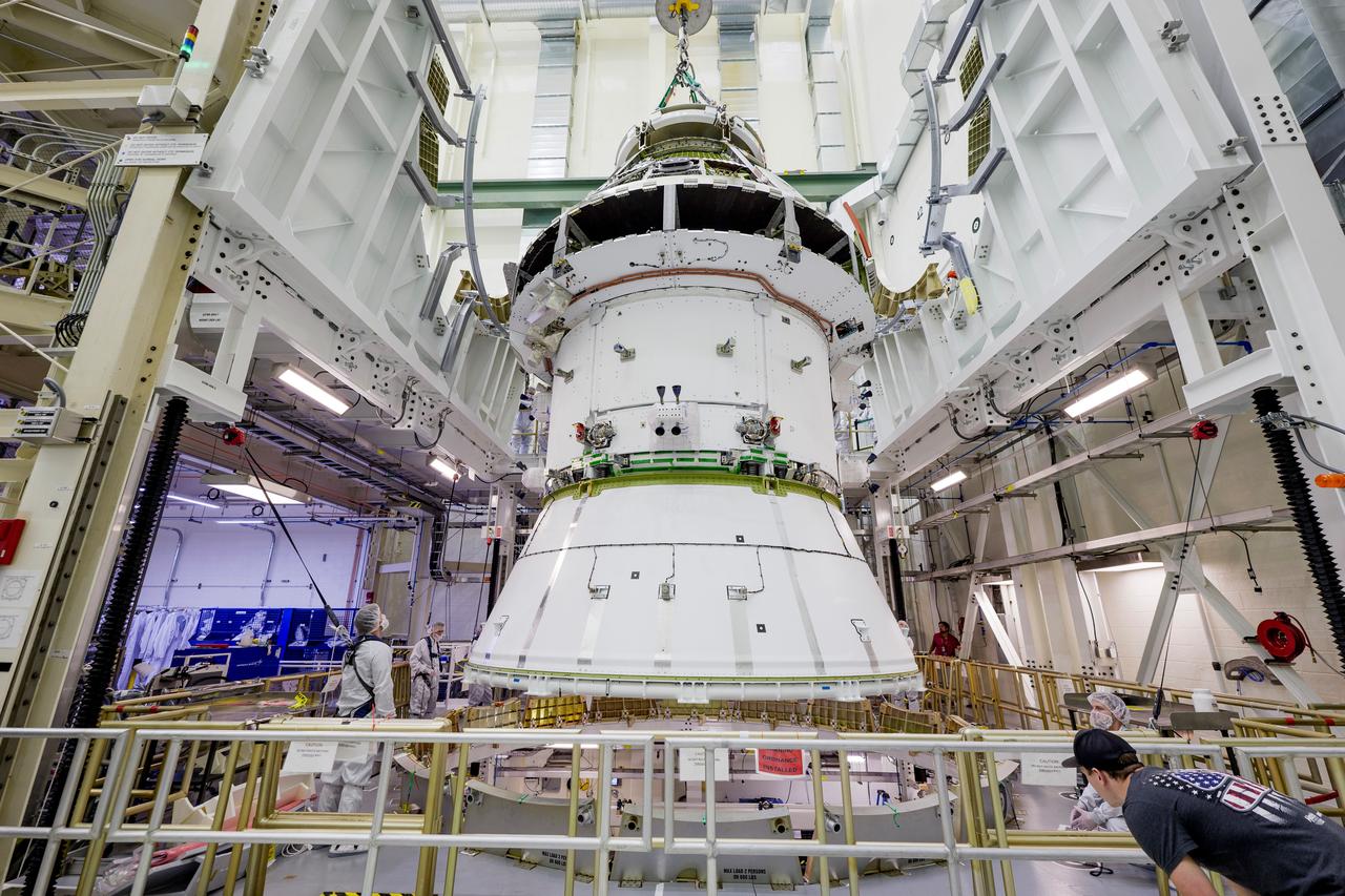
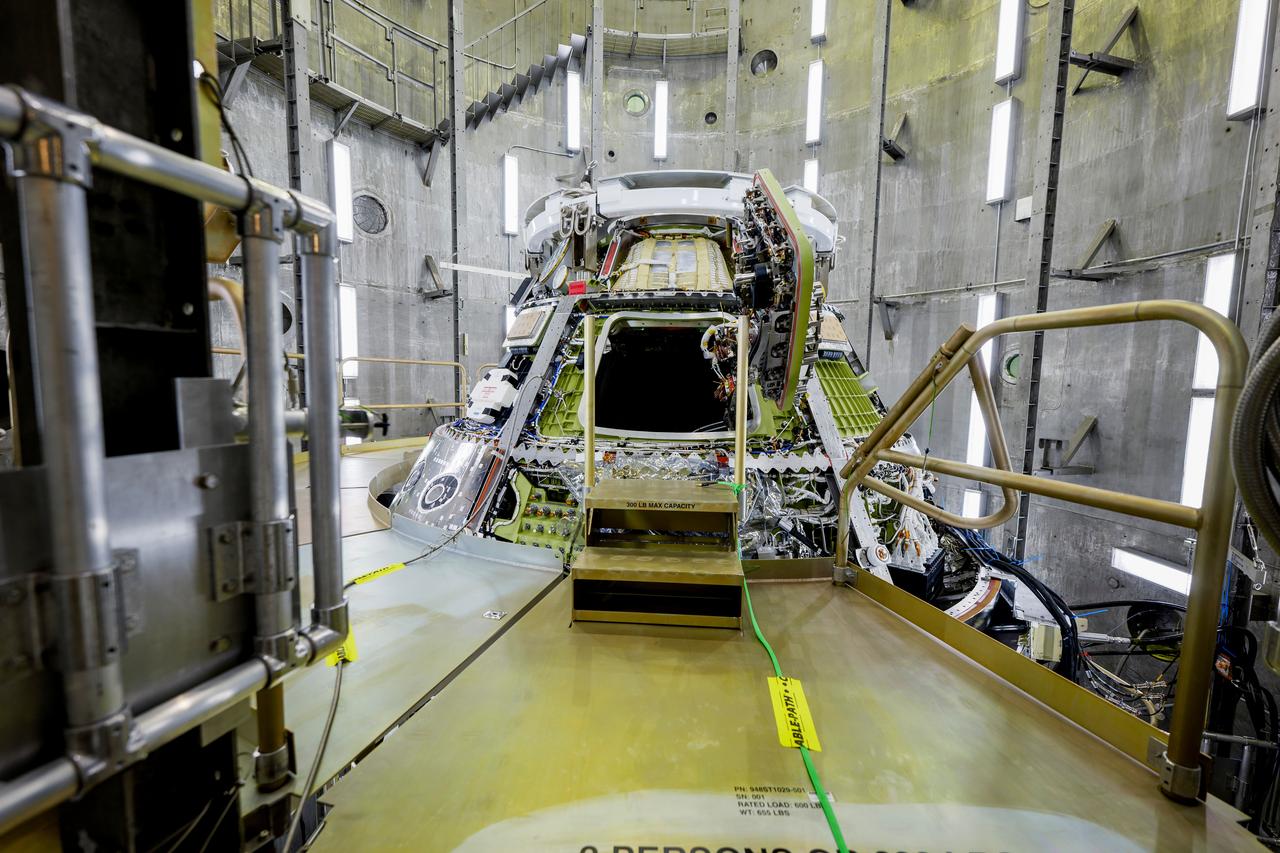
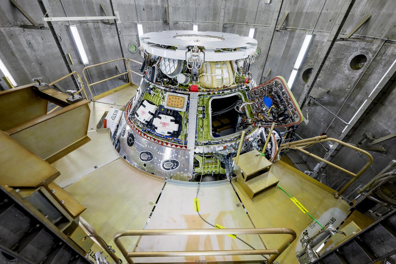
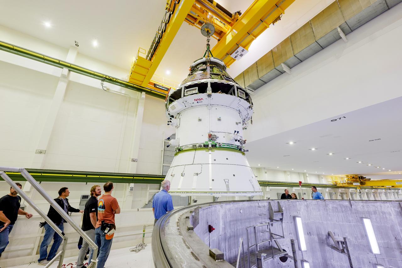
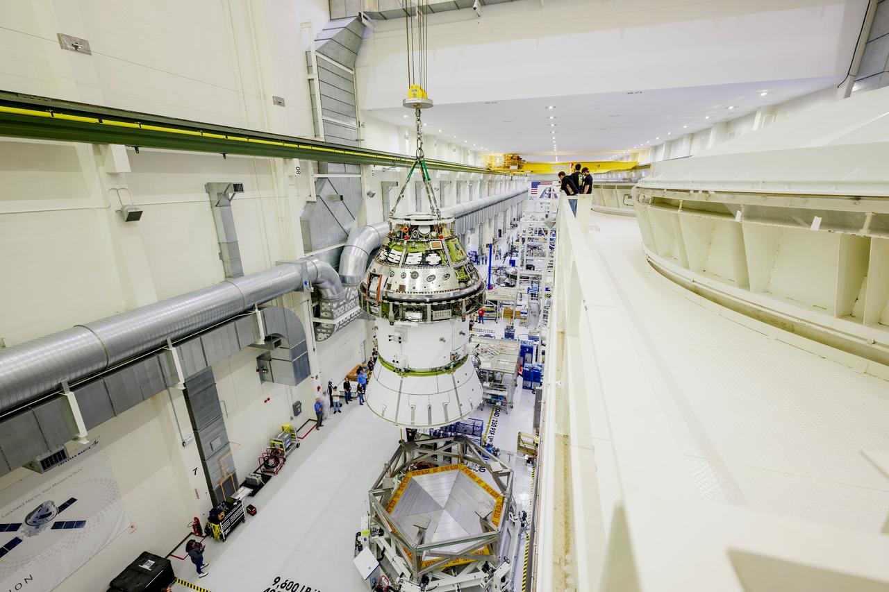
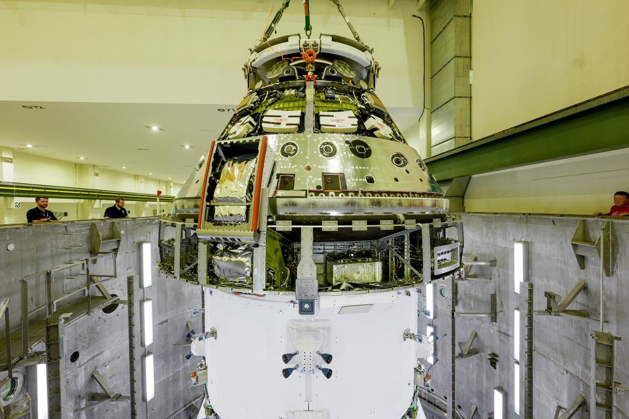
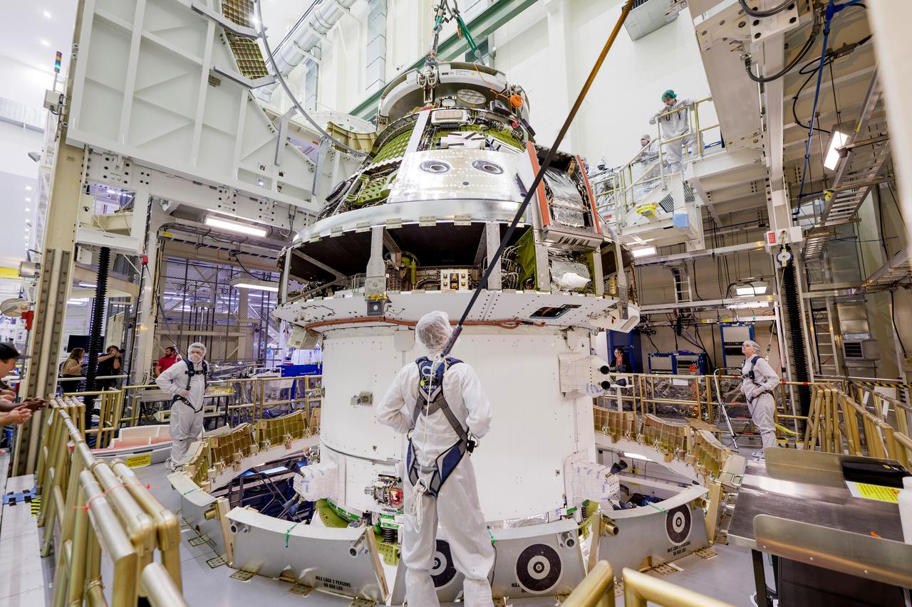
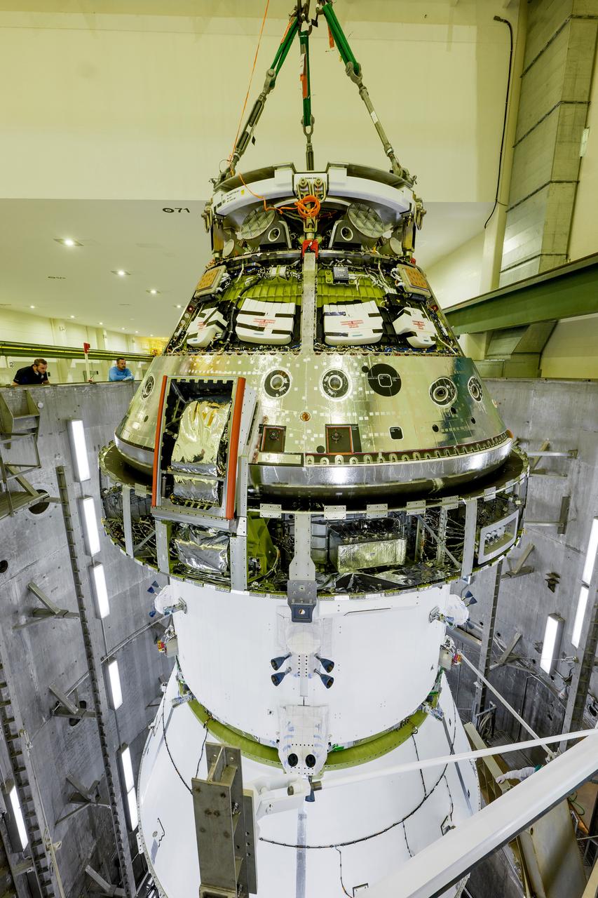
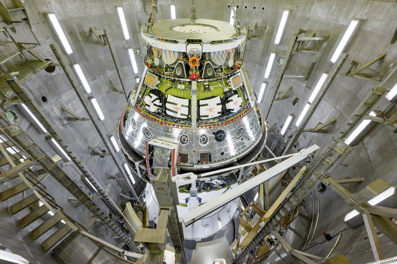
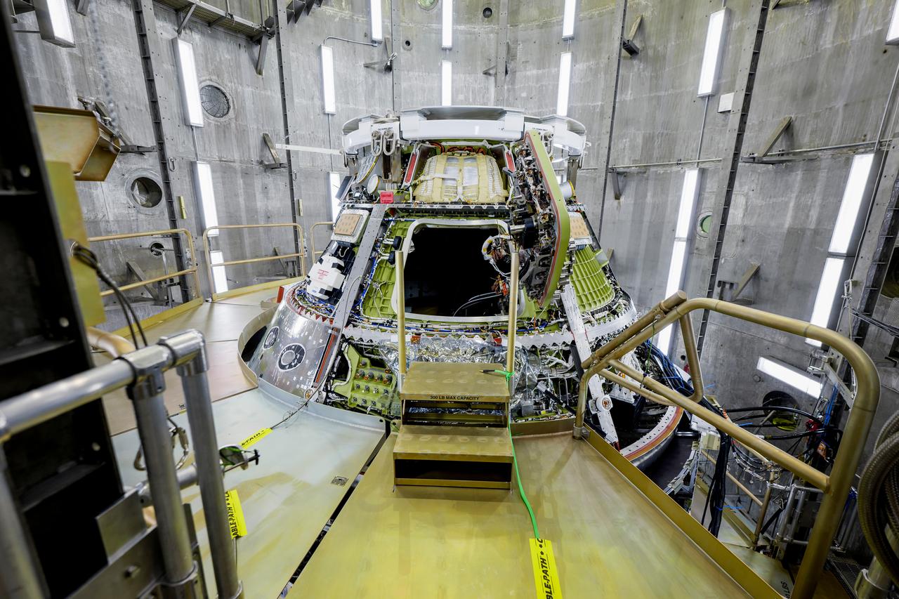
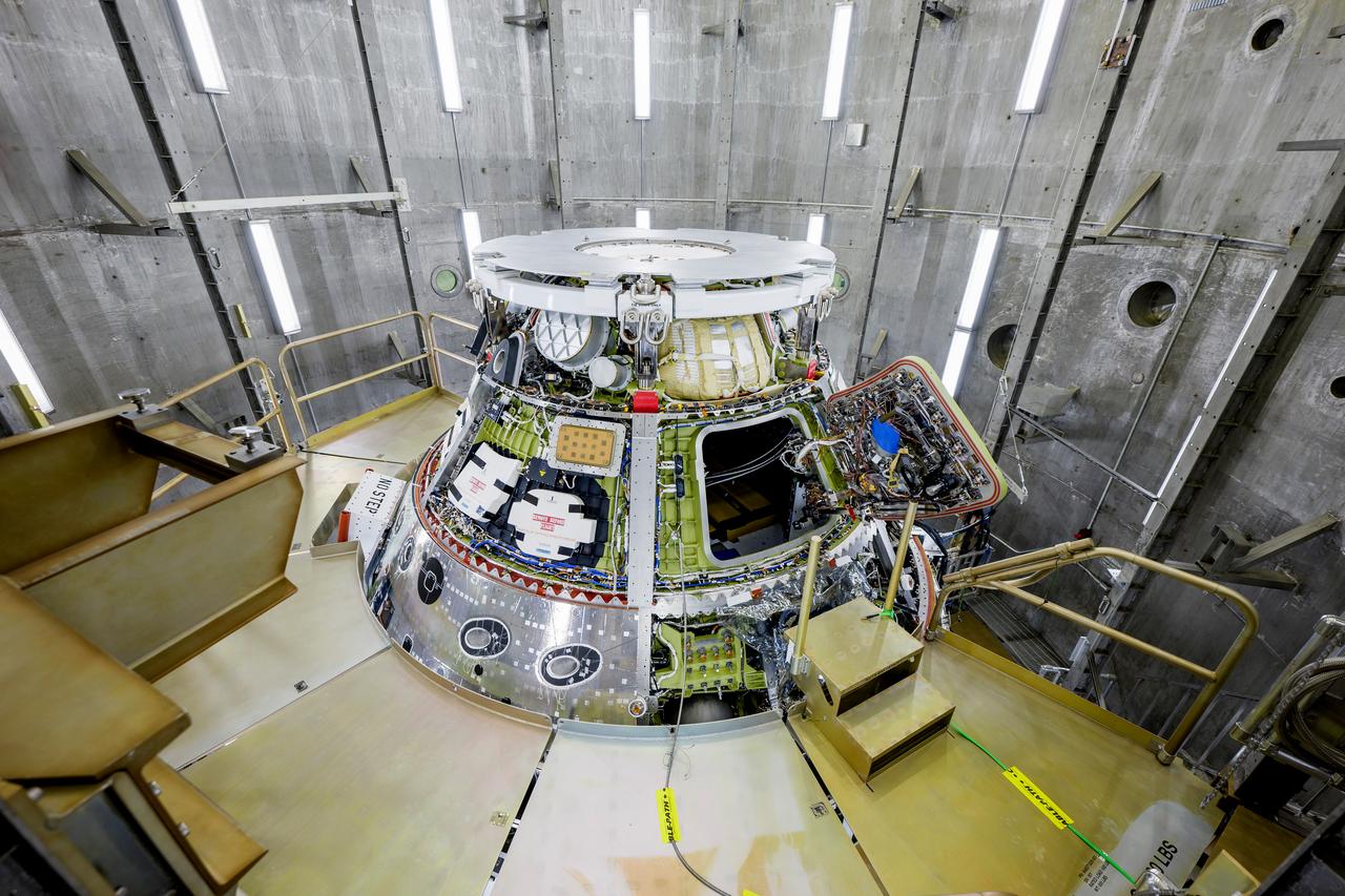
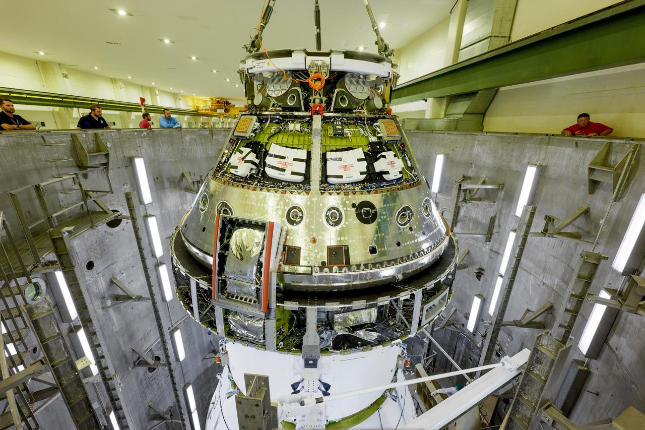
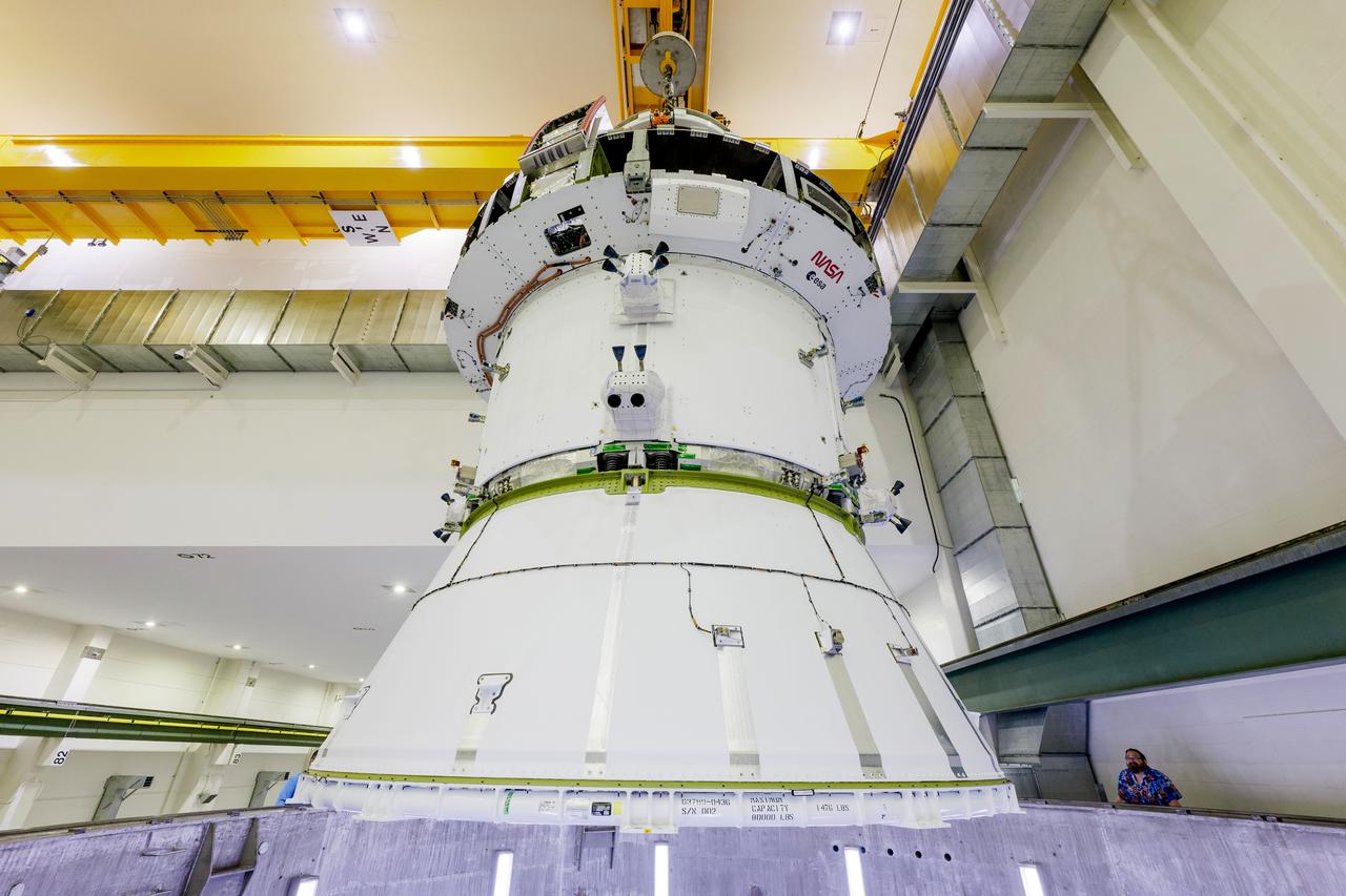
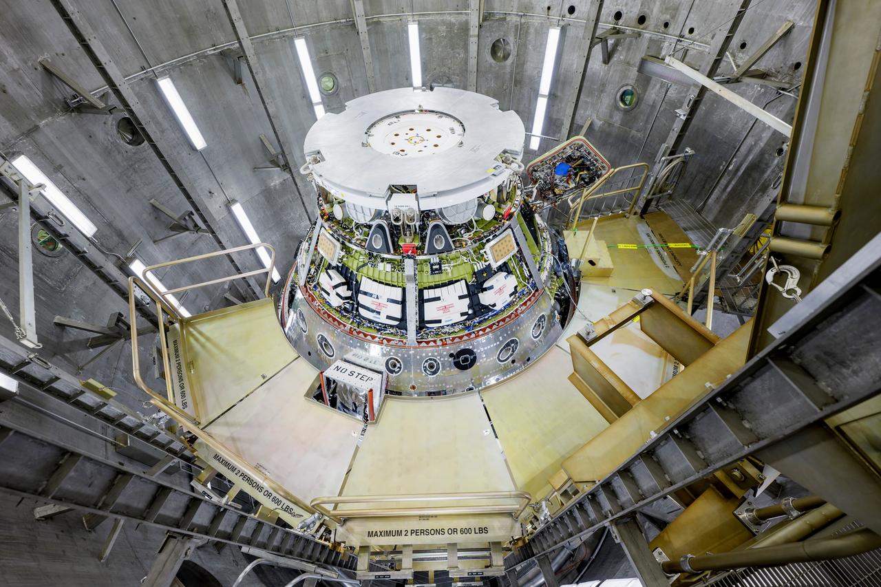
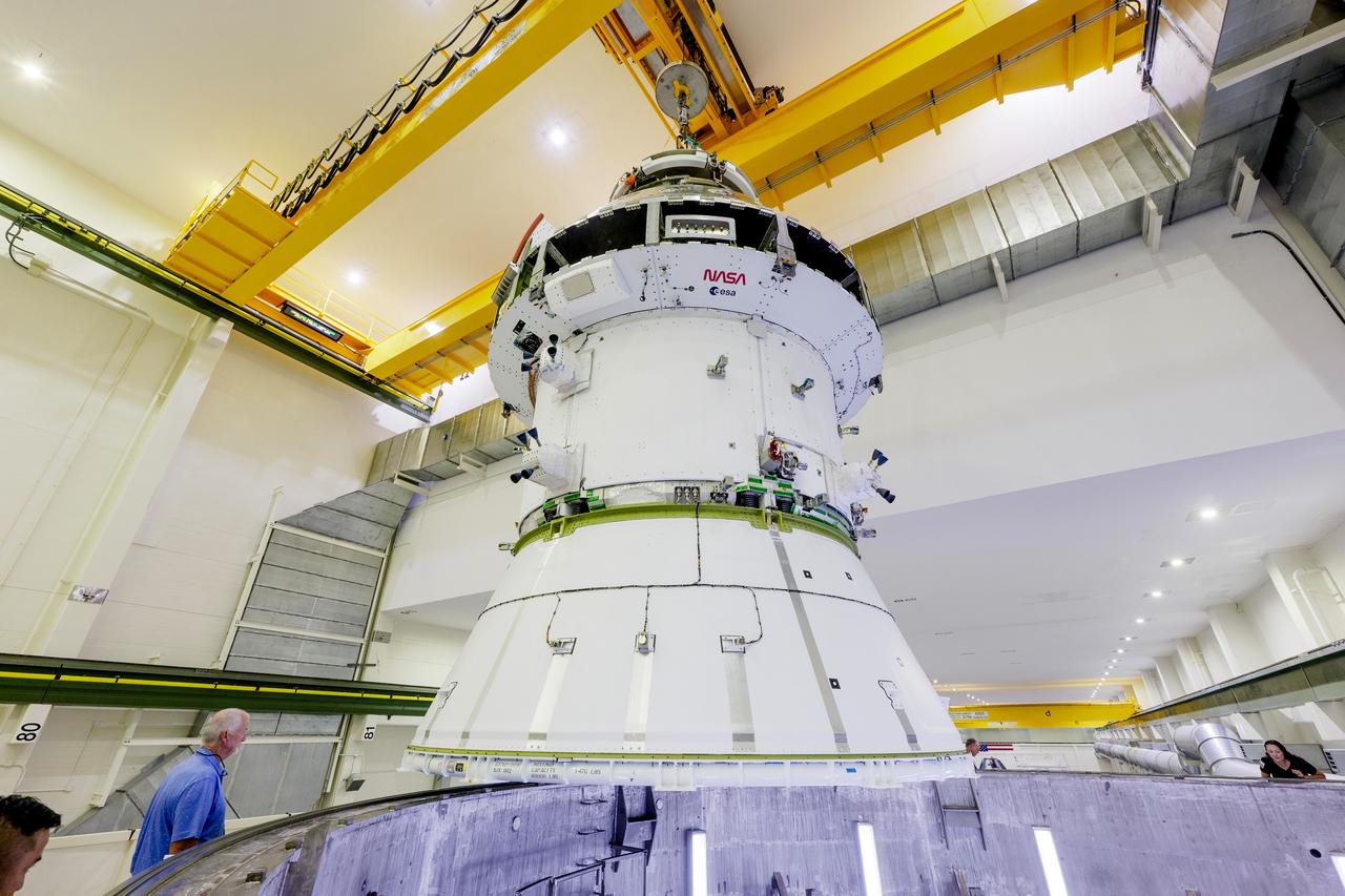
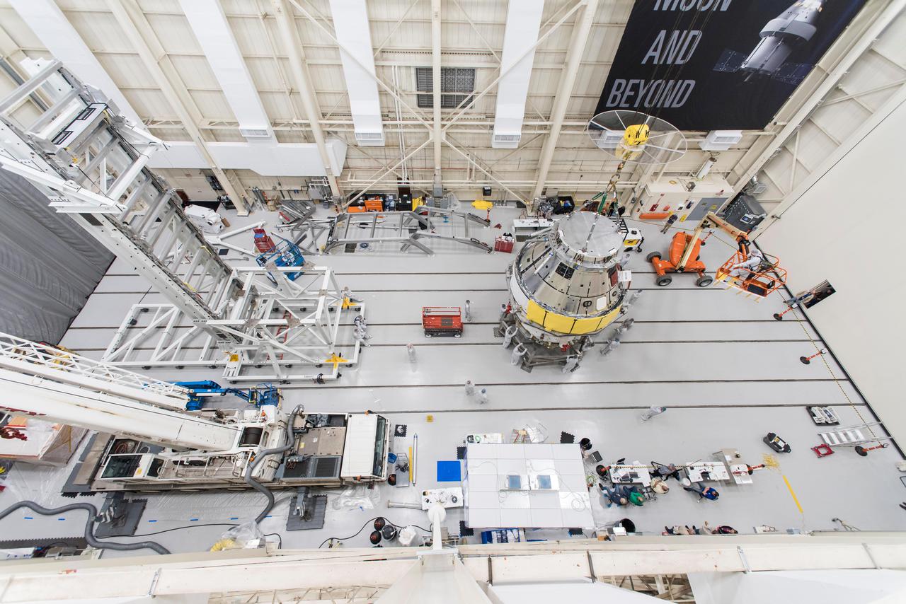
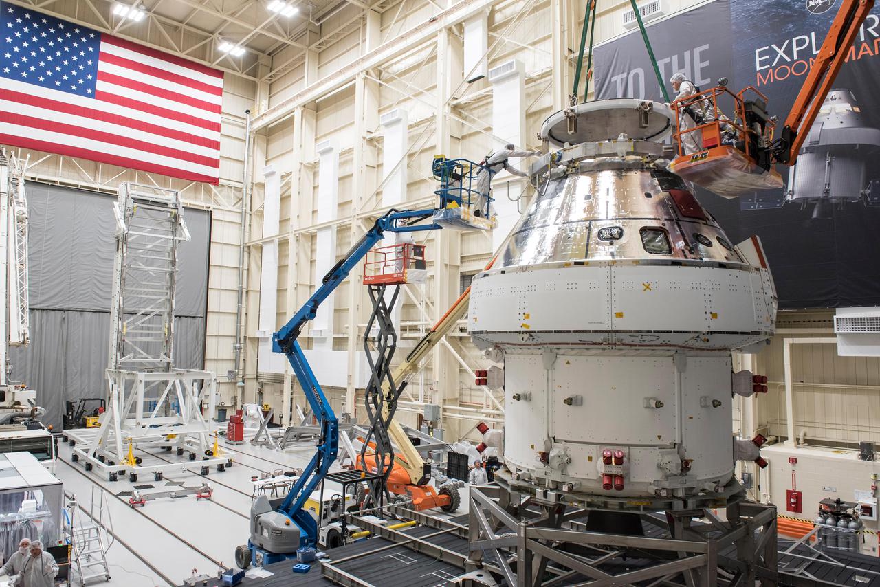
The Artemis II Orion spacecraft is lifted from the Final Assembly and Testing (FAST) Cell and placed in the west altitude chamber inside the Operations and Checkout Building at NASA’S Kennedy Space Center in Florida on June 28, 2024. Inside the altitude chamber, the spacecraft underwent a series of tests simulating deep space vacuum conditions. Photo Credit: NASA / Rad Sinyak
The Artemis II Orion spacecraft is lifted from the Final Assembly and Testing (FAST) Cell and placed in the west altitude chamber inside the Operations and Checkout Building at NASA’S Kennedy Space Center in Florida on June 28, 2024. Inside the altitude chamber, the spacecraft underwent a series of tests simulating deep space vacuum conditions. Photo Credit: NASA / Rad Sinyak
The Artemis II Orion spacecraft is lifted from the Final Assembly and Testing (FAST) Cell and placed in the west altitude chamber inside the Operations and Checkout Building at NASA’S Kennedy Space Center in Florida on June 28, 2024. Inside the altitude chamber, the spacecraft underwent a series of tests simulating deep space vacuum conditions. Photo Credit: NASA / Rad Sinyak
The Artemis II Orion spacecraft is lifted from the Final Assembly and Testing (FAST) Cell and placed in the west altitude chamber inside the Operations and Checkout Building at NASA’S Kennedy Space Center in Florida on June 28, 2024. Inside the altitude chamber, the spacecraft underwent a series of tests simulating deep space vacuum conditions. Photo Credit: NASA / Rad Sinyak
The Artemis II Orion spacecraft is lifted from the Final Assembly and System Testing (FAST) Cell and placed in the west altitude chamber inside the Operations and Checkout Building at NASA’S Kennedy Space Center in Florida on June 28, 2024. Inside the altitude chamber, the spacecraft underwent a series of tests simulating deep space vacuum conditions. Photo Credit: NASA / Rad Sinyak

The Artemis II Orion spacecraft is lifted from the Final Assembly and System Testing (FAST) Cell and placed in the west altitude chamber inside the Operations and Checkout Building at NASA’S Kennedy Space Center in Florida on June 28, 2024. Inside the altitude chamber, the spacecraft underwent a series of tests simulating deep space vacuum conditions. Photo Credit: NASA / Rad Sinyak
The Artemis II Orion spacecraft is lifted from the Final Assembly and Testing (FAST) Cell and placed in the west altitude chamber inside the Operations and Checkout Building at NASA’S Kennedy Space Center in Florida on June 28, 2024. Inside the altitude chamber, the spacecraft underwent a series of tests simulating deep space vacuum conditions. Photo Credit: NASA / Rad Sinyak
The Artemis II Orion spacecraft is lifted from the Final Assembly and Testing (FAST) Cell and placed in the west altitude chamber inside the Operations and Checkout Building at NASA’S Kennedy Space Center in Florida on June 28, 2024. Inside the altitude chamber, the spacecraft underwent a series of tests simulating deep space vacuum conditions. Photo Credit: NASA / Rad Sinyak
The Artemis II Orion spacecraft is lifted from the Final Assembly and Testing (FAST) Cell and placed in the west altitude chamber inside the Operations and Checkout Building at NASA’S Kennedy Space Center in Florida on June 28, 2024. Inside the altitude chamber, the spacecraft underwent a series of tests simulating deep space vacuum conditions. Photo Credit: NASA / Rad Sinyak
The Artemis II Orion spacecraft is lifted from the Final Assembly and Testing (FAST) Cell and placed in the west altitude chamber inside the Operations and Checkout Building at NASA’S Kennedy Space Center in Florida on June 28, 2024. Inside the altitude chamber, the spacecraft underwent a series of tests simulating deep space vacuum conditions. Photo Credit: NASA / Rad Sinyak
The Artemis II Orion spacecraft is lifted from the Final Assembly and System Testing (FAST) Cell and placed in the west altitude chamber inside the Operations and Checkout Building at NASA’S Kennedy Space Center in Florida on June 28, 2024. Inside the altitude chamber, the spacecraft underwent a series of tests simulating deep space vacuum conditions. Photo Credit: NASA / Rad Sinyak
The Artemis II Orion spacecraft is lifted from the Final Assembly and Testing (FAST) Cell and placed in the west altitude chamber inside the Operations and Checkout Building at NASA’S Kennedy Space Center in Florida on June 28, 2024. Inside the altitude chamber, the spacecraft underwent a series of tests simulating deep space vacuum conditions. Photo Credit: NASA / Rad Sinyak
The Artemis II Orion spacecraft is lifted from the Final Assembly and Testing (FAST) Cell and placed in the west altitude chamber inside the Operations and Checkout Building at NASA’S Kennedy Space Center in Florida on June 28, 2024. Inside the altitude chamber, the spacecraft underwent a series of tests simulating deep space vacuum conditions. Photo Credit: NASA / Rad Sinyak
The Artemis II Orion spacecraft is lifted from the Final Assembly and Testing (FAST) Cell and placed in the west altitude chamber inside the Operations and Checkout Building at NASA’S Kennedy Space Center in Florida on June 28, 2024. Inside the altitude chamber, the spacecraft underwent a series of tests simulating deep space vacuum conditions. Photo Credit: NASA / Rad Sinyak

The Artemis II Orion spacecraft is lifted from the Final Assembly and Testing (FAST) Cell and placed in the west altitude chamber inside the Operations and Checkout Building at NASA’S Kennedy Space Center in Florida on June 28, 2024. Inside the altitude chamber, the spacecraft underwent a series of tests simulating deep space vacuum conditions. Photo Credit: NASA / Rad Sinyak
The Artemis II Orion spacecraft is lifted from the Final Assembly and Testing (FAST) Cell and placed in the west altitude chamber inside the Operations and Checkout Building at NASA’S Kennedy Space Center in Florida on June 28, 2024. Inside the altitude chamber, the spacecraft underwent a series of tests simulating deep space vacuum conditions. Photo Credit: NASA / Rad Sinyak
The Artemis II Orion spacecraft is lifted from the Final Assembly and System Testing (FAST) Cell and placed in the west altitude chamber inside the Operations and Checkout Building at NASA’S Kennedy Space Center in Florida on June 28, 2024. Inside the altitude chamber, the spacecraft underwent a series of tests simulating deep space vacuum conditions. Photo Credit: NASA / Rad Sinyak
The Artemis II Orion spacecraft is lifted from the Final Assembly and Testing (FAST) Cell and placed in the west altitude chamber inside the Operations and Checkout Building at NASA’S Kennedy Space Center in Florida on June 28, 2024. Inside the altitude chamber, the spacecraft underwent a series of tests simulating deep space vacuum conditions. Photo Credit: NASA / Rad Sinyak
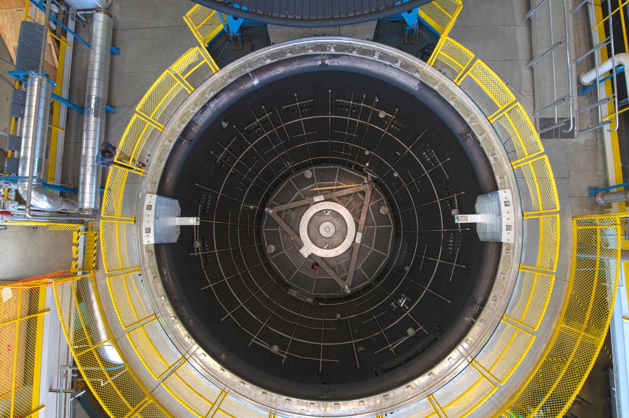
The vacuum chamber of the In-Space Propulsion (ISP) facility at the Neil Armstrong Test Facility spans 38ft in diameter and is 62ft tall. ISP is the world’s only facility capable of full-scale rocket engine and launch vehicle system level tests. ISP also has a vacuum range of up to 100 statute miles in altitude. This is a view from inside the chamber. Photo Credit: (NASA/Jordan Salkin)
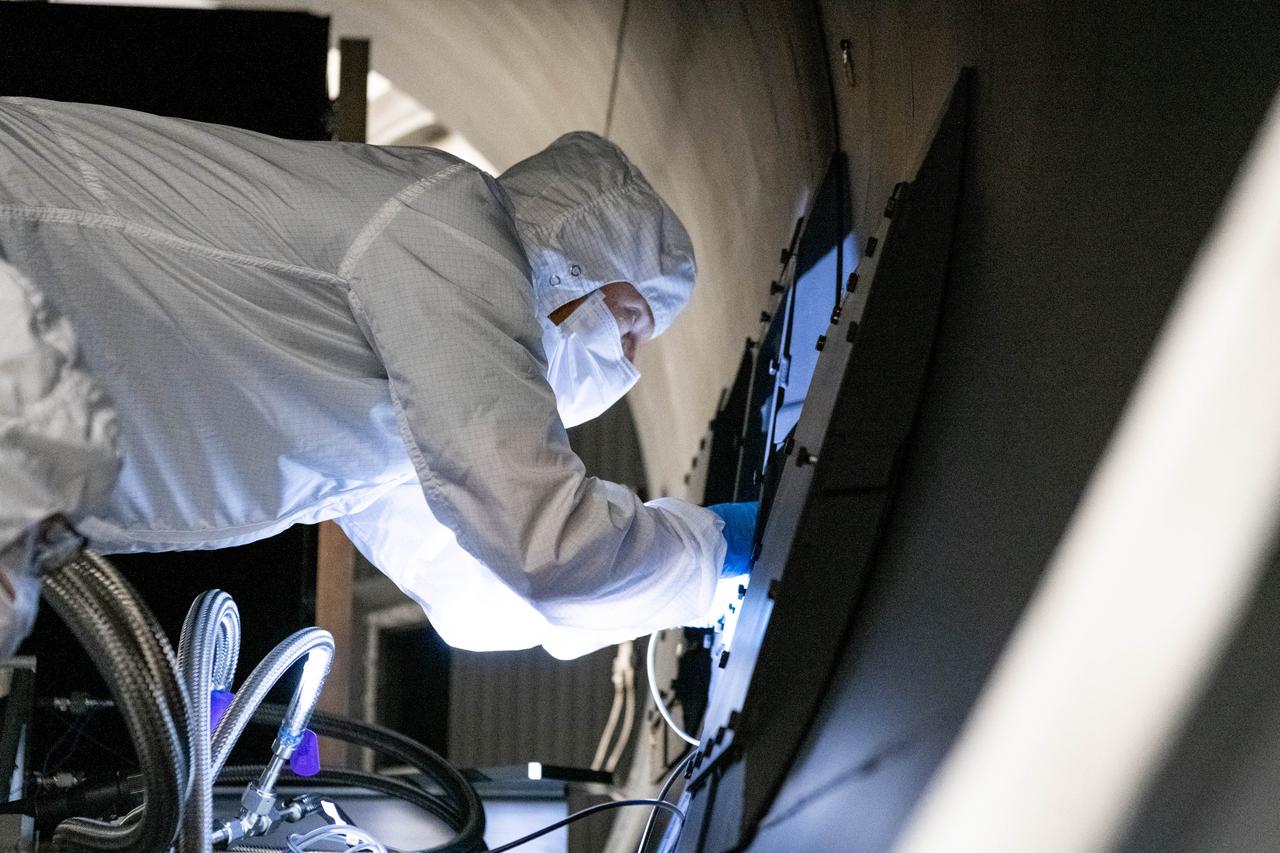
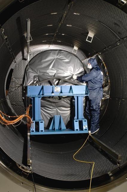
Optical engineer, Brendan McAndrew, installs radiometers inside the Ocean Color Instrument (OCI) thermal vacuum chamber in preparation for window calibration testing. The testing will help scientists and engineers know if the optical components of OCI are aligned correctly before it gets integrated to the PACE (Plankton, Aerosol, Cloud, ocean Ecosystem) spacecraft. OCI is a highly advanced optical spectrometer that will be used to measure properties of light over portions of the electromagnetic spectrum. It will enable continuous measurement of light at finer wavelength resolution than previous NASA satellite sensors, extending key system ocean color data records for climate studies. OCI is PACE's (Plankton, Aerosol, Cloud, ocean Ecosystem) primary sensor built at Goddard Space Flight Center in Greenbelt, MD.
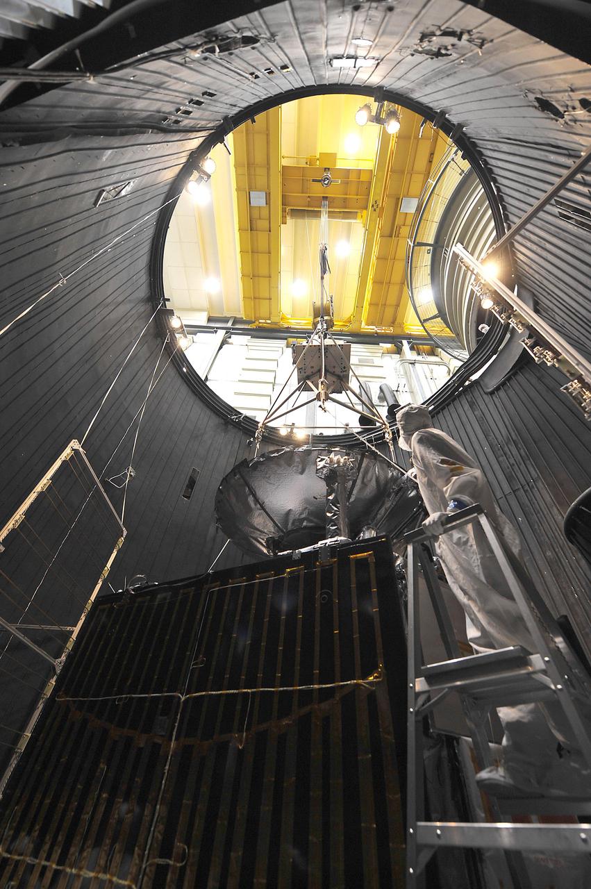
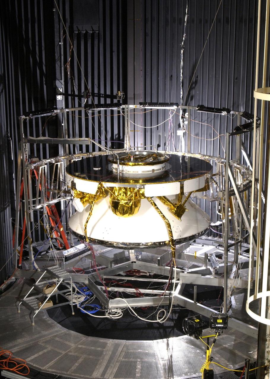
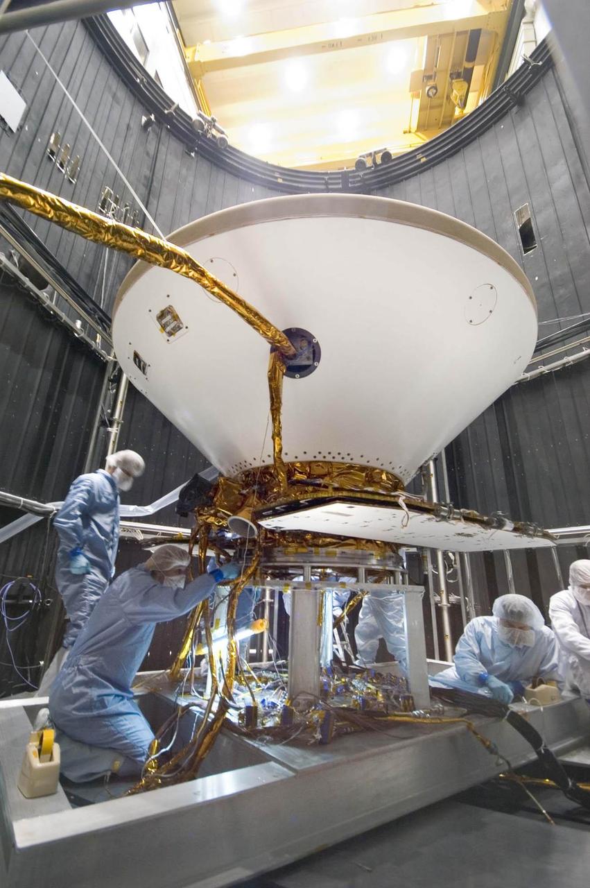
This image of NASA Juno spacecraft was taken as the vehicle completed its thermal vacuum chamber testing. A technician is attaching the lifting equipment in preparation for hoisting the 1,588-kilogram 3,500-pound spacecraft out of the chamber.
Preparations for a shroud jettison test for the Orbiting Astronomical Observatory-1 (OAO-1) satellite in the Space Power Chambers facility at the National Aeronautics and Space Administration (NASA) Lewis Research Center. The satellite was to be launched on an Atlas-Agena rocket in the spring of 1966. The 3900-pound payload was the heaviest ever attempted by Agena. The satellite was the first of three equipped with powerful telescopes to study ultraviolet data from specific stars and galaxies. In-depth observations were not possible from Earth-bound telescopes because of the filtering and distortion of the atmosphere. The OAO-1 satellite was wider in diameter than the Agena stage, so a new clamshell shroud was created to enclose both the satellite and the Agena. The clamshell shroud consisted of three sections that enclosed both the Agena and OAO-1: a fiberglass nose fairing and aluminum mid and aft fairings. The upper two fairings separated when the Atlas engines stopped, and the aft fairing fell away with the Atlas upon separation from the upper stages The large altitude tank in the Space Power Chambers could simulate altitudes up to 100,000 feet. Three shroud jettison tests were run in July 1965 and the first week of August at a simulated altitude of 20 miles. The April 8, 1966 launch from Cape Canaveral went smoothly, but the OAO-1 satellite failed after only 90 minutes due to a battery failure.
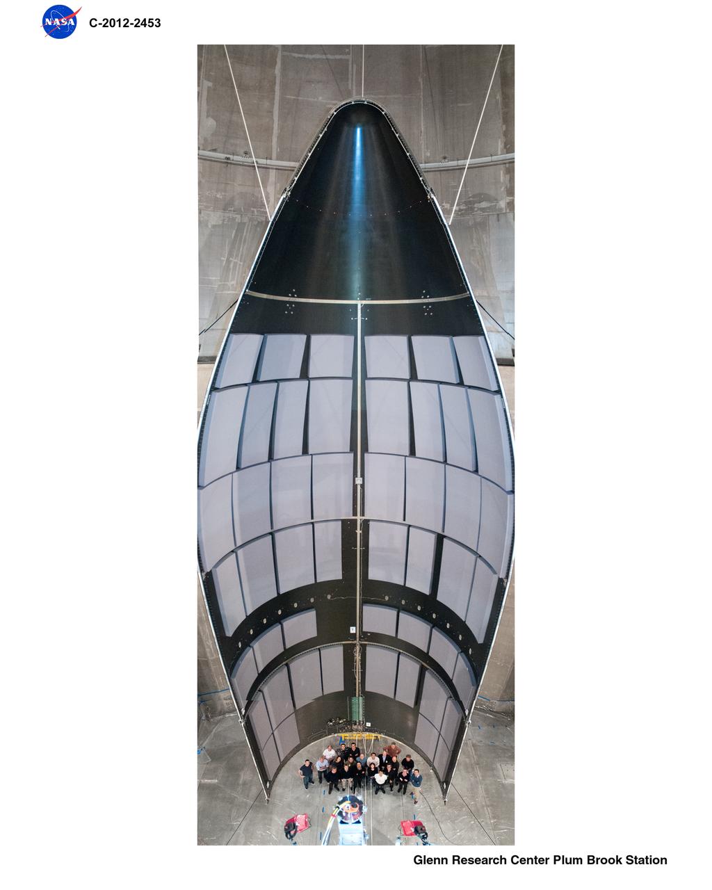
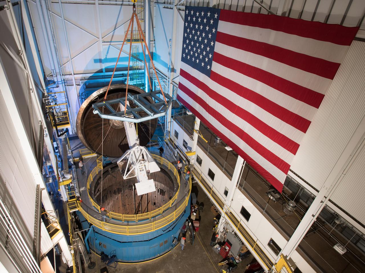
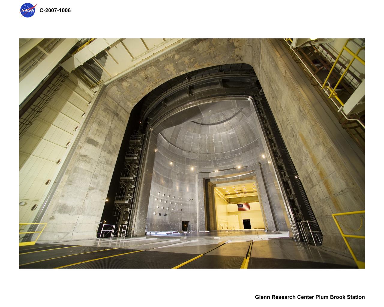
Space Power Facility at Plum Brook Station, RUAG Ariane 5 Shroud Separation Tests. GRC has the world's largest vacuum chamber in the world. This world class facility is host to many space launch vehicle systems tests from customer's in this country and from around the world. Shown here is the post test of a successful rocket shroud separation test. The shroud, or top of a rocket, is jettisoned into two halves with explosive charges to allow the payload to be exposed for deployment. The payload, often time is a satellite, would be sitting atop the center white section shown in the middle of the photo. This photo was taken from on top of the rocket holding the payload and both halves of the rocket shroud looking down at one of the shroud halves and the test crew at the bottom.
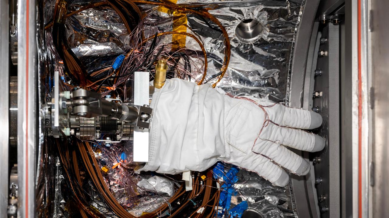
An astronaut glove designed for use during spacewalks on the International Space Station is prepared for thermal vacuum testing inside a chamber at NASA's Jet Propulsion Laboratory in Southern California on Nov. 1, 2023. The glove lies in a load lock, one of four small drawer-like chambers through which test materials are inserted into the larger main chamber of a facility called CITADEL (Cryogenic Ice Testing, Acquisition Development, and Excavation Laboratory). The glove was tested at vacuum and temperatures as low as minus 352 degrees Fahrenheit (minus 213 degrees Celsius) – temperatures as frigid as those Artemis III astronauts could experience on the Moon's South Pole. Built to prepare potential future robotic spacecraft for the frosty, low-pressure conditions on ocean worlds like Jupiter's frozen moon Europa, CITADEL has also proven key to evaluating how astronaut gloves and boots hold up in extraordinary cold. The NASA Engineering and Safety Center spearheaded a glove testing campaign in CITADEL from October 2023 to March 2024. Part of a spacesuit design called the Extravehicular Mobility Unit, the gloves tested in the chamber are the sixth version of a glove NASA began using in the 1980s. The testing in CITADEL showed that the legacy glove would not meet thermal requirements in the more challenging lunar South Pole environment. In addition to spotting vulnerabilities with existing suits, the CITADEL experiments will help NASA develop this unique test capability and prepare criteria for standardized, repeatable, and inexpensive test methods for the next-generation lunar suit being built by Axiom Space. https://photojournal.jpl.nasa.gov/catalog/PIA26430
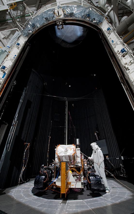
NASA Rover 1 in the cruise configuration in Jet Propulsion Laboratory 25-ft Solar Thermal Vacuum Chamber where it underwent environmental testing.
An ion thruster is removed from a vacuum chamber at NASA Jet Propulsion Laboratory, Pasadena, Calif., its job done following almost five years of testing.
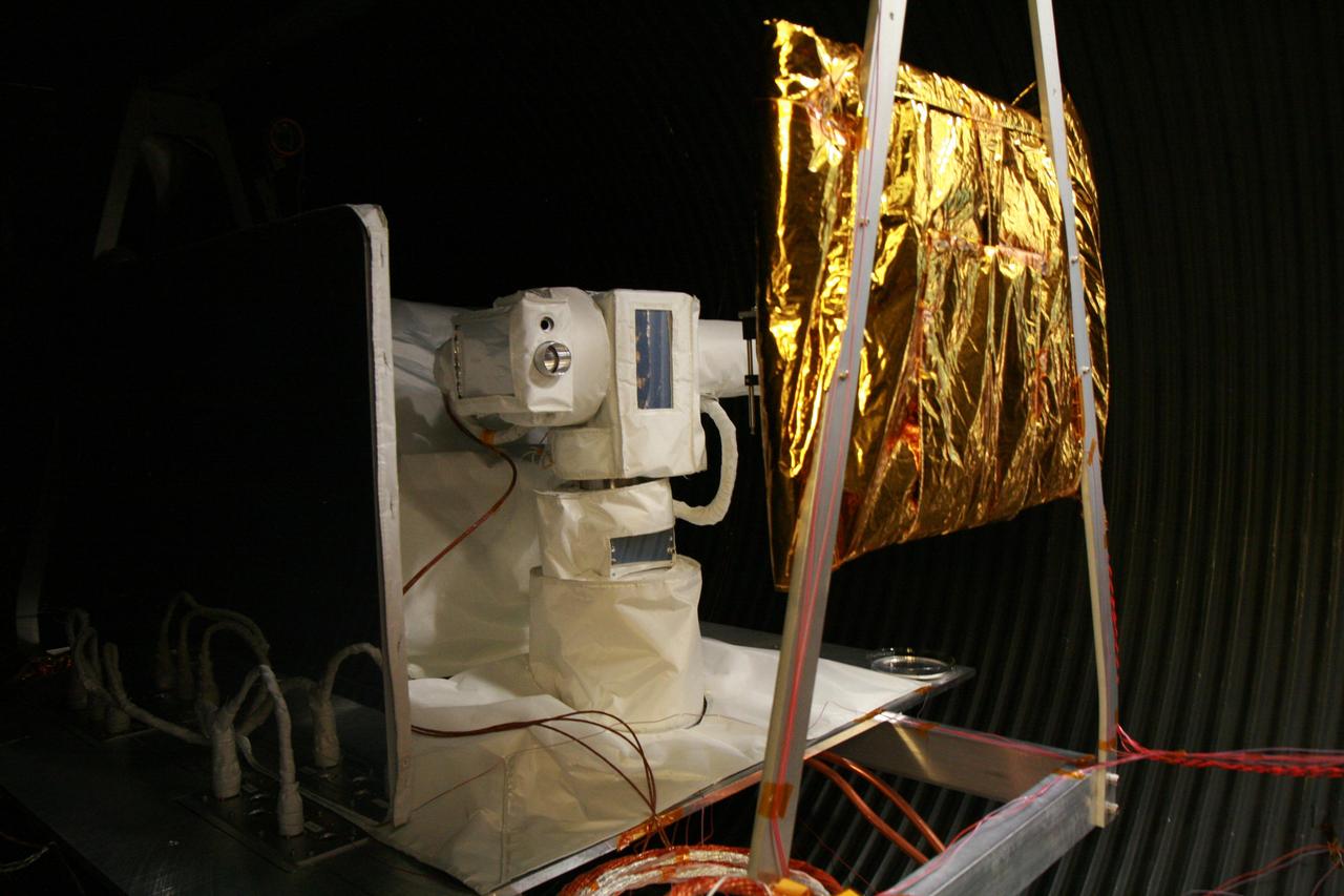
The Optical PAyload for Lasercomm Science OPALS flight terminal undergoes testing in a thermal vacuum chamber at NASA Jet Propulsion Laboratory to simulate the space environment.
A technician slides an imaging spectrometer instrument, which will measure the greenhouse gases methane and carbon dioxide from space, into a thermal vacuum test chamber at NASA's Jet Propulsion Laboratory in Southern California in July 2023. The thermal vacuum chamber test is one of a series meant to ensure that the instrument can withstand the rigors of launch and the harsh conditions of space. Engineers use the chamber to subject the spectrometer to the extreme temperatures it will encounter in the vacuum of space. The instrument shipped Sept. 12, 2023, from JPL to Planet Labs PBC in San Francisco, where it will be integrated into a Tanager satellite. Designed and built by JPL, imaging spectrometer will be part of an effort led by the nonprofit Carbon Mapper organization to collect data on greenhouse gas point-source emissions. The information will help locate and quantify "super-emitters" – the small percentage of individual sources responsible for a significant fraction of methane and carbon dioxide emissions around the world. Movie available at https://photojournal.jpl.nasa.gov/catalog/PIA26098

The Roman Coronagraph Instrument, a technology demonstration that will be part of NASA's Nancy Grace Roman Space Telescope, is seen amid testing at the agency's Jet Propulsion Laboratory in Southern California in December 2023. During this test in a special isolated, electromagnetically quiet chamber, the instrument was peppered with radio waves to test its response to ensure that the electrical components on the instrument don't interfere with those on the rest of the observatory, and vice versa. The test was performed inside a chamber lined with foam padding that absorbs the radio waves to prevent them from bouncing off the walls. https://photojournal.jpl.nasa.gov/catalog/PIA26273
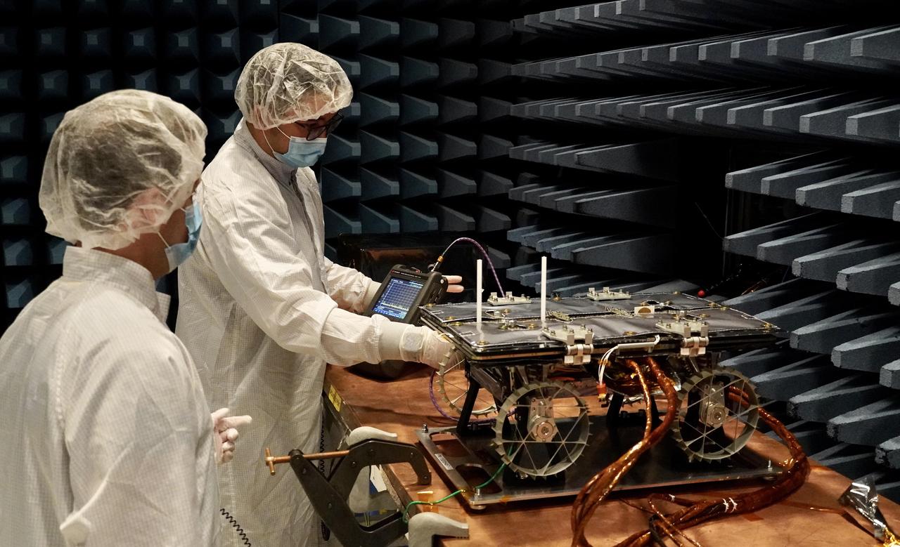
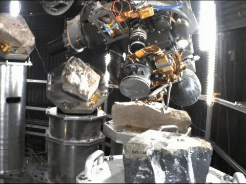
In a special chamber at NASA's Jet Propulsion Laboratory, engineers prepare to test a small rover that will go to the Moon as part of a NASA technology demonstration called CADRE (Cooperative Autonomous Distributed Robotic Exploration). The project is designed to show that a group of robotic spacecraft can work together as a team to accomplish tasks and record data autonomously – without explicit commands from mission controllers on Earth. This electromagnetic interference and compatibility testing took place in November 2023 in a chamber designed to absorb radio waves. Such testing is intended to confirm that the operation of the electronic subsystems do not interfere with each other nor with those on the lander, and that the rover can survive expected electromagnetic disturbances. Justin Schachter, left, and Manny Soriano are shown. https://photojournal.jpl.nasa.gov/catalog/PIA26166
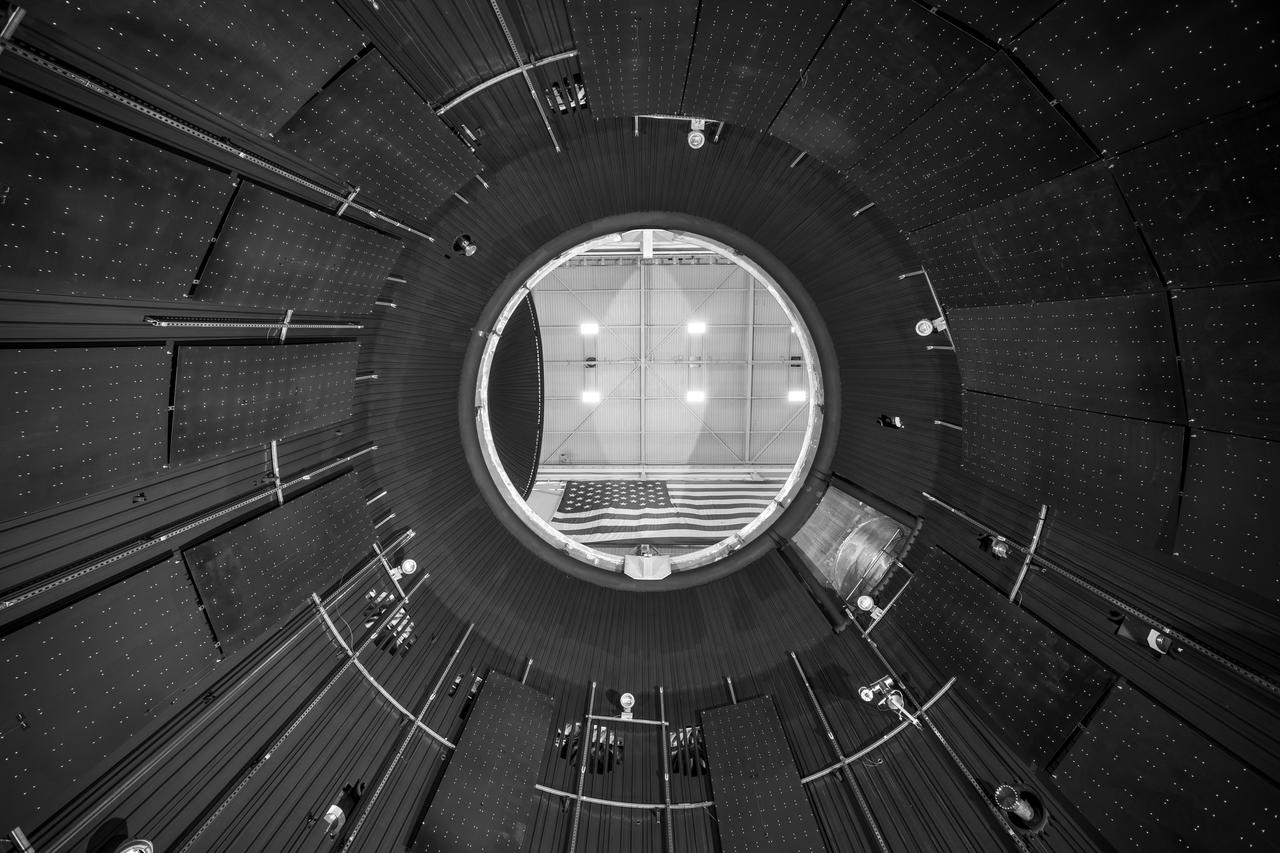
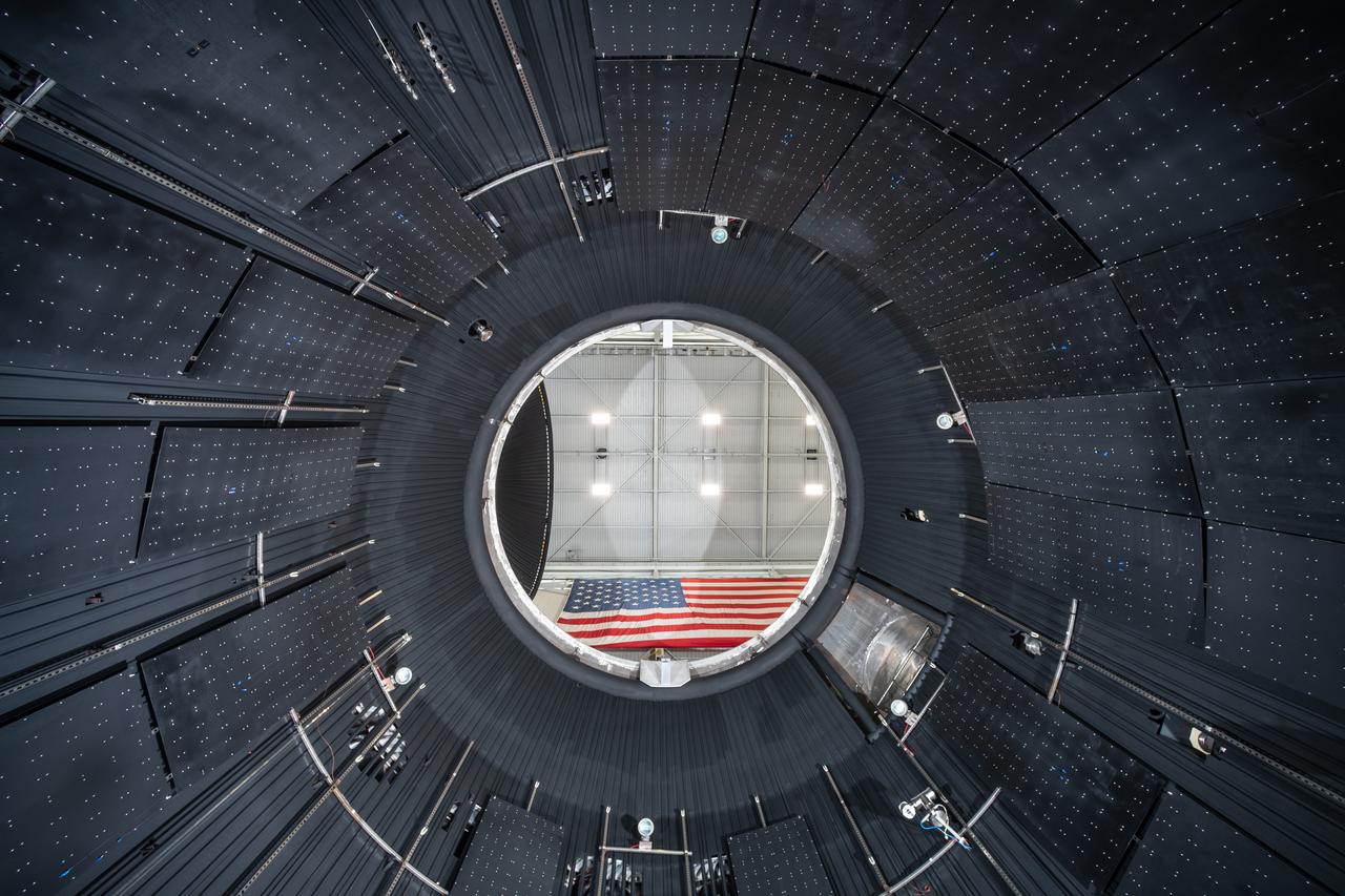
NASA’s In-Space Propulsion Facility located at Neil Armstrong Test Facility in Sandusky Ohio is the world’s only high altitude test facility capable of full-scale rocket engine and launch vehicle system level tests. The facility supports mission profile thermal vacuum simulation and engine firing. The engine or vehicle can be exposed for indefinite periods to low ambient pressures, low-background temperatures, and dynamic solar heating, simulating the environment the hardware will encounter during orbital or interplanetary travel. This is a view from inside the chamber looking up toward the American flag. Photo Credit: (NASA/Jordan Salkin)

Engineers at Lockheed Martin Space, Denver, Colorado, prepare NASA's InSight lander for testing in a thermal vacuum chamber several months before launch. https://photojournal.jpl.nasa.gov/catalog/PIA22740
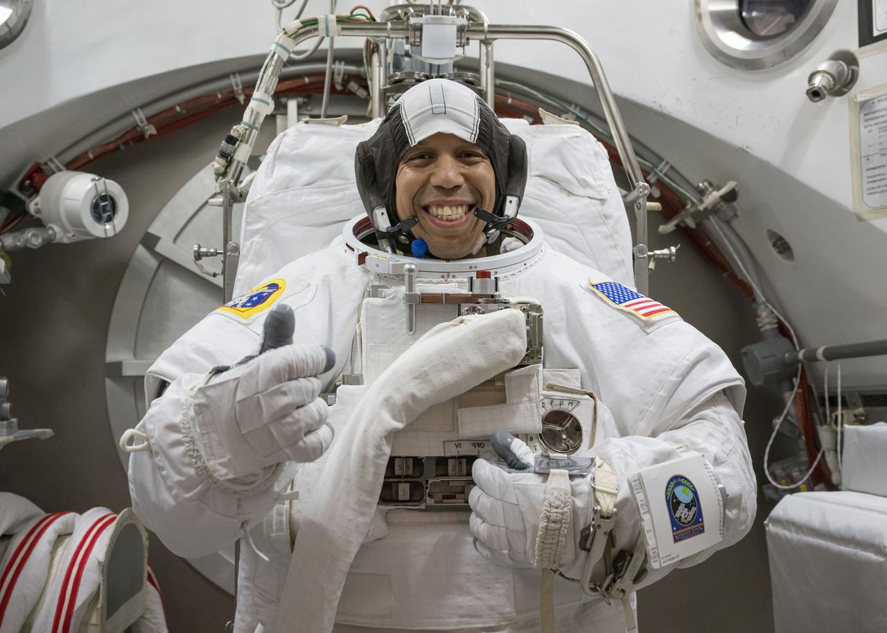
jsc2025e044433 (May 6, 2025) --- NASA astronaut Chris Williams poses for a photo in an Extravehicular Mobility Unit spacesuit during vacuum chambers testing at NASA’s Johnson Space Center in Houston, Texas.
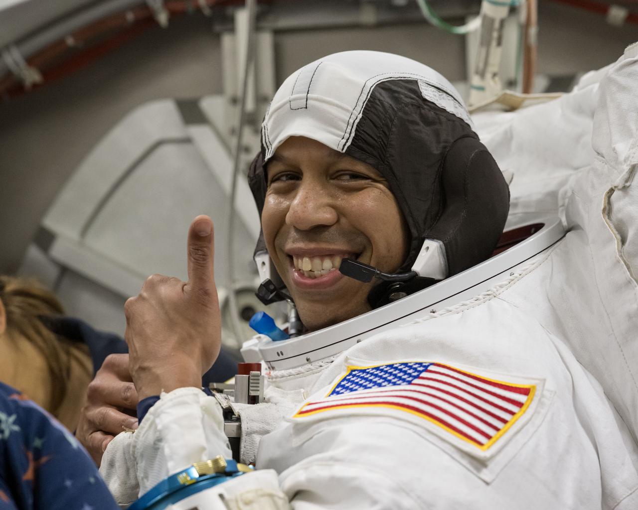
jsc2025e044425 (May 6, 2025) --- NASA astronaut Chris Williams poses for a photo in an Extravehicular Mobility Unit spacesuit during vacuum chambers testing at NASA’s Johnson Space Center in Houston, Texas.
Orion - EM-1 - Artemis Spacecraft Departure at the Space Environments Complex, SEC Thermal Vacuum Chamber at the Neil A. Armstrong Test Facility, Transportation to Mansfield Lahm Airport
Orion - EM-1 - Artemis Spacecraft Departure at the Space Environments Complex, SEC Thermal Vacuum Chamber at the Neil A. Armstrong Test Facility, Transportation to Mansfield Lahm Airport
This animated GIF shows the deployment of the Perseverance rover's remote sensing mast during a cold test in a space simulation chamber at NASA's Jet Propulsion Laboratory. The test took place in October 2019. Movie available at https://photojournal.jpl.nasa.gov/catalog/PIA23889
NASA Juno spacecraft is raised out of a thermal vacuum chamber following tests that simulated the environment of space over the range of conditions the probe will encounter during its mission.
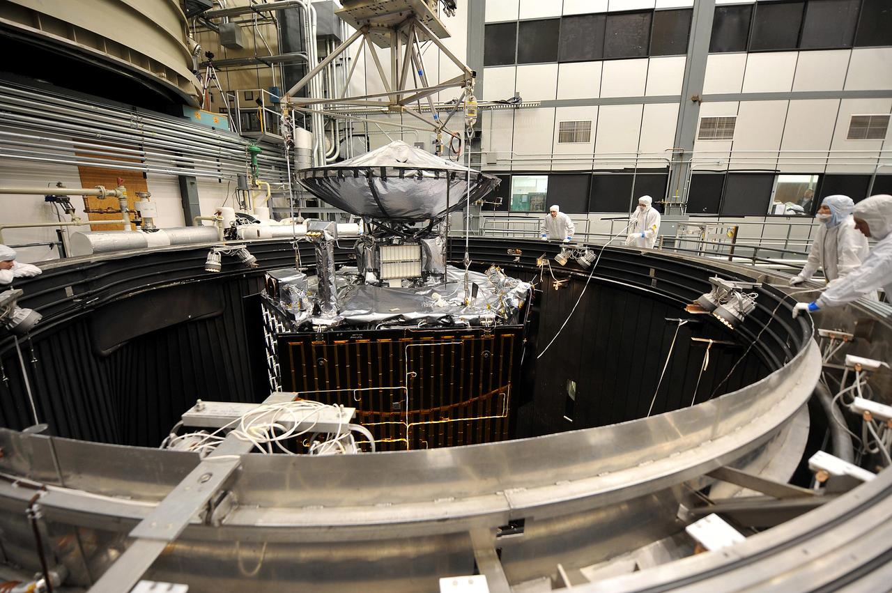
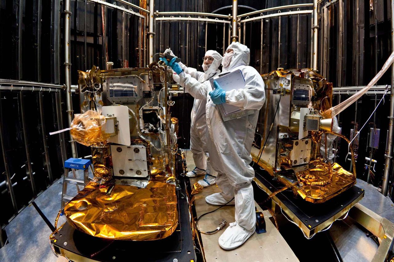
This image shows preparation for March 2011 testing of the Mars Science Laboratory rover, Curiosity, in a space-simulation chamber; the rover will go through operational sequences in environmental conditions similar to what it will experience on Mars.
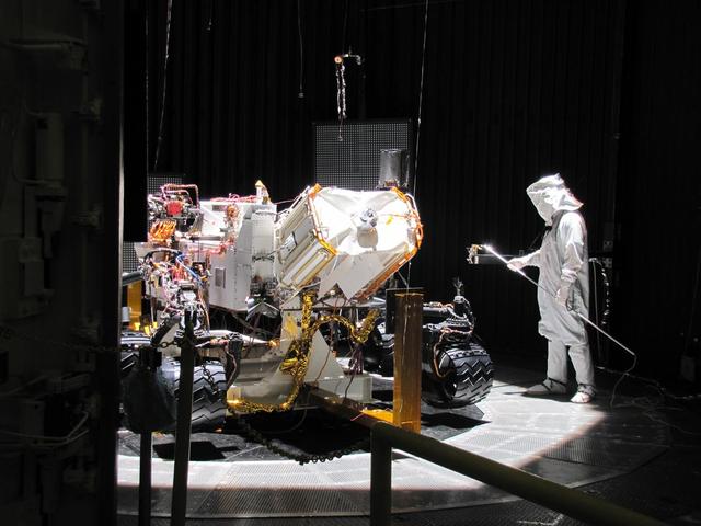
This image shows preparation for March 2011 testing of the Mars Science Laboratory rover, Curiosity, in a space-simulation chamber; the rover will go through operational sequences in environmental conditions similar to what it will experience on Mars.
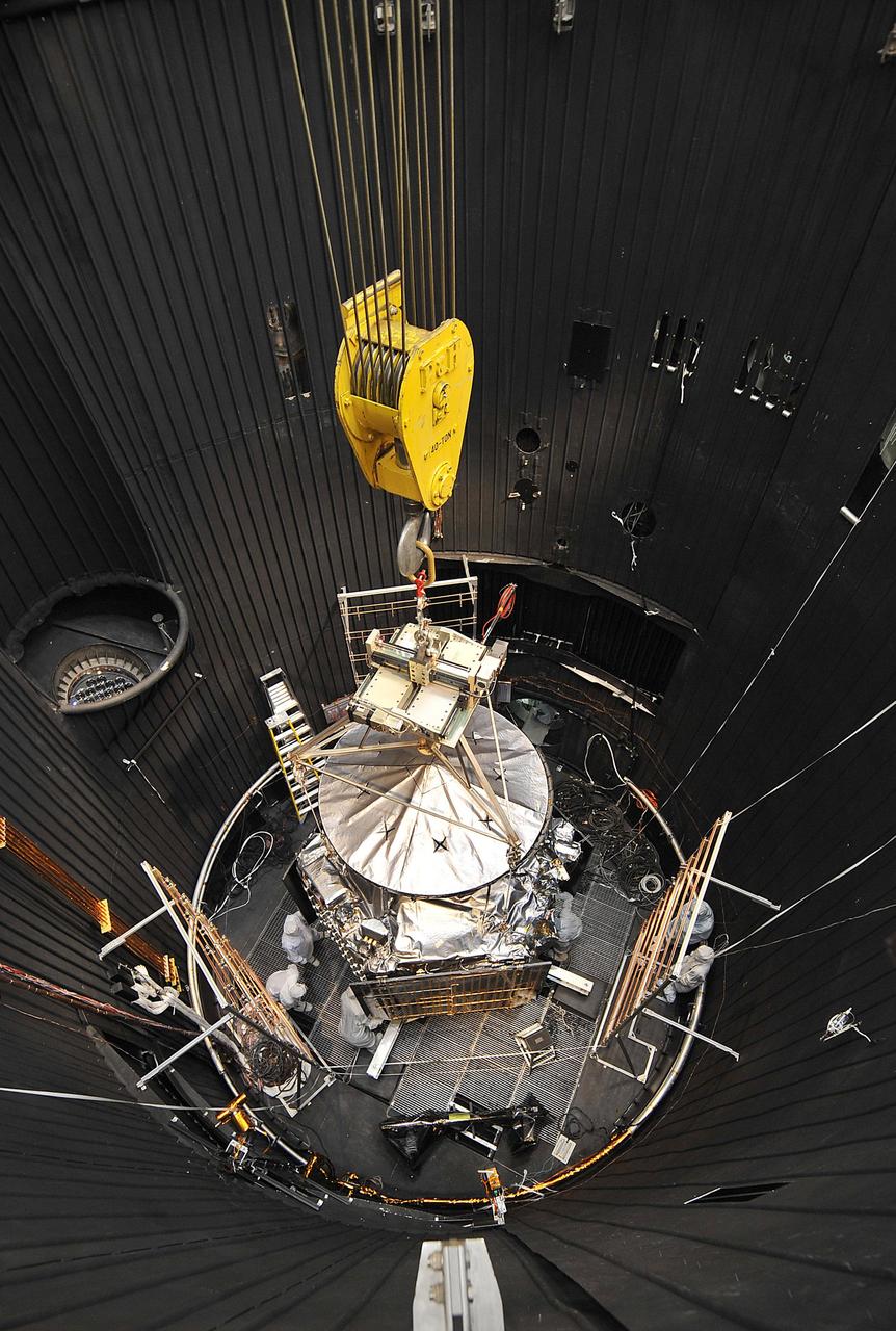
NASA Juno spacecraft is readied for lifting out of a thermal vacuum chamber following testing to simulate the environment of space over the range of conditions the probe will encounter during its mission.

This archival photo shows the Voyager proof test model, which did not fly in space, in the 25-foot space simulator chamber at NASA's Jet Propulsion Laboratory on December 3, 1976. https://photojournal.jpl.nasa.gov/catalog/PIA21735
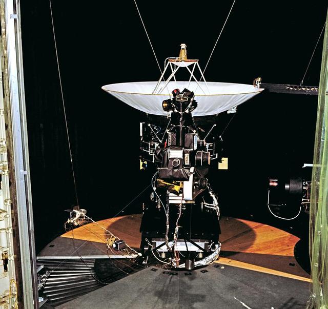
This archival photo shows the Voyager proof test model, which did not fly in space, in the 25-foot space simulator chamber at NASA's Jet Propulsion Laboratory, Pasadena, California. https://photojournal.jpl.nasa.gov/catalog/PIA21726
In this photo, taken April 29, 2011, technicians install lifting brackets prior to hoisting the 200-kilogram 440-pound GRAIL-A spacecraft out of vacuum chamber after testing.
The Gamma-Ray Imager/Polarimeter for Solar flares (GRIPS) instrument is installed in the B-2 vacuum chamber for a full-instrument thermal-vacuum test in 2015. The GRIPS telescope was launched via balloon in January 2016 on a high-altitude flight over Antarctica to study the acceleration and transport of solar flare particles.
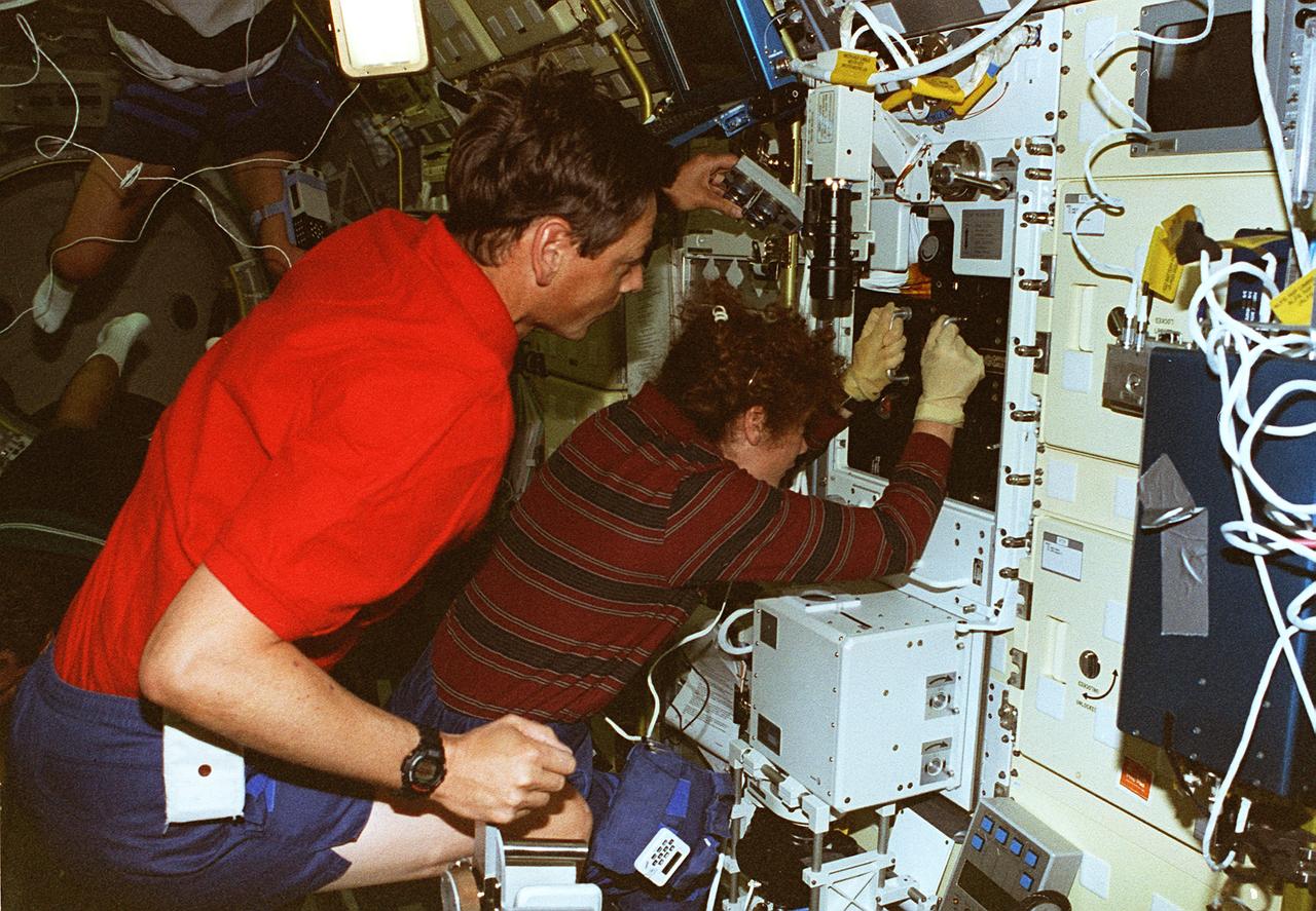
STS078-306-035 (20 June - 7 July 1996) --- Astronaut Susan J. Helms, payload commander, and payload specialist Jean-Jacques Favier, representing the French Space Agency (CNES), insert a test container into the Bubble Drop Particle Unit (BDPU) in the Life and Microgravity Spacelab (LMS-1) Science Module aboard the Space Shuttle Columbia. The fluid in the chamber is heated and the fluid processes are observed by use of three internal cameras mounted inside the BDPU. Investigations in this facility will help characterize interfacial processes involving either bubbles, drops, liquid columns or liquid layers.
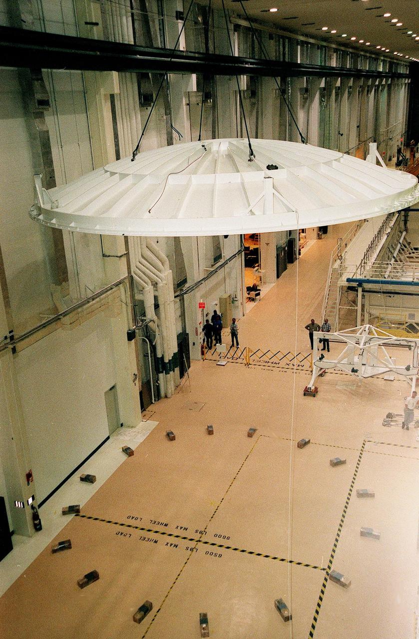
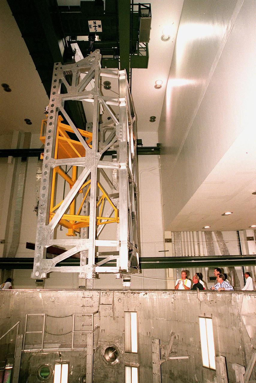
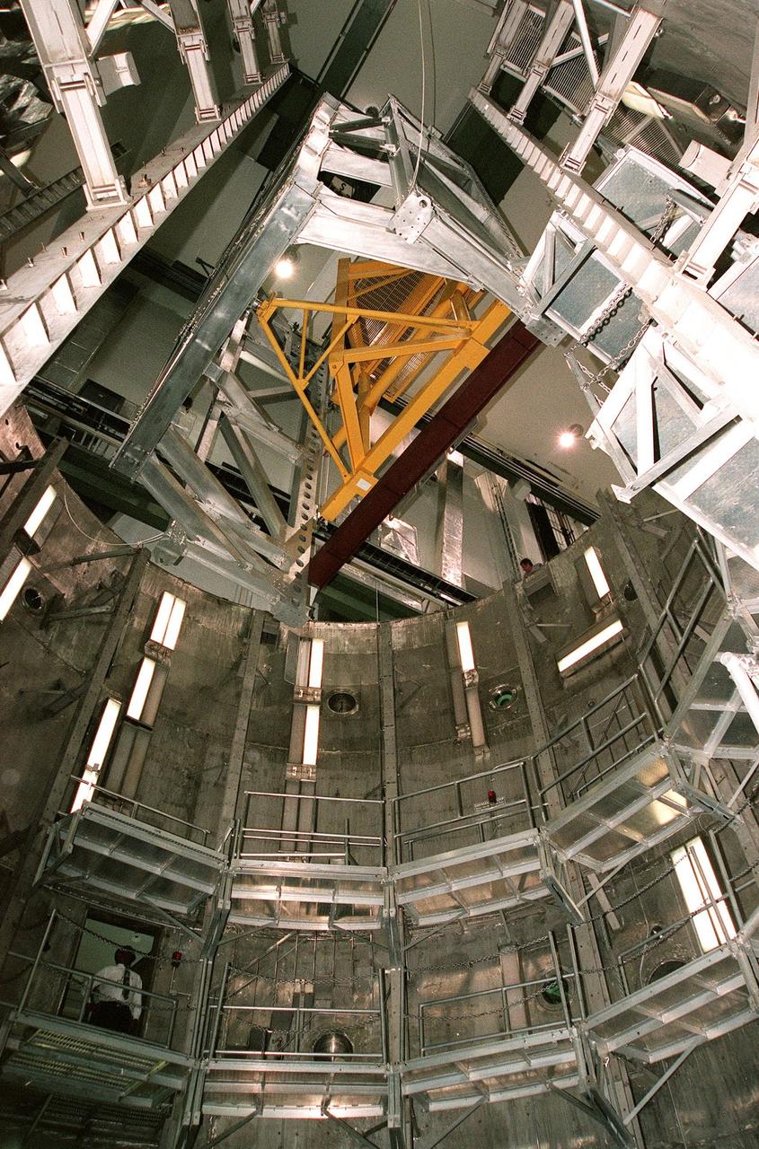
KENNEDY SPACE CENTER, FLA. -- Looking as if poised in flight, the saucer-like lid of an altitude chamber is lifted from the floor in the Operations and Checkout Building high bay to its place on top of the chamber. The chamber was recently reactivated, after a 24-year hiatus, to perform leak tests on International Space Station pressurized modules at the launch site. Originally, two chambers were built to test Apollo Program flight hardware. They were last used in 1975 during the Apollo-Soyuz Test Project. After installation of new vacuum pumping equipment and controls, a new control room, and a new rotation handling fixture, the chamber again became operational in February 1999. The chamber, which is 33 feet in diameter and 50 feet tall, is constructed of stainless steel. The first module that will be tested for leaks is the U.S. Laboratory. No date has been determined for the test
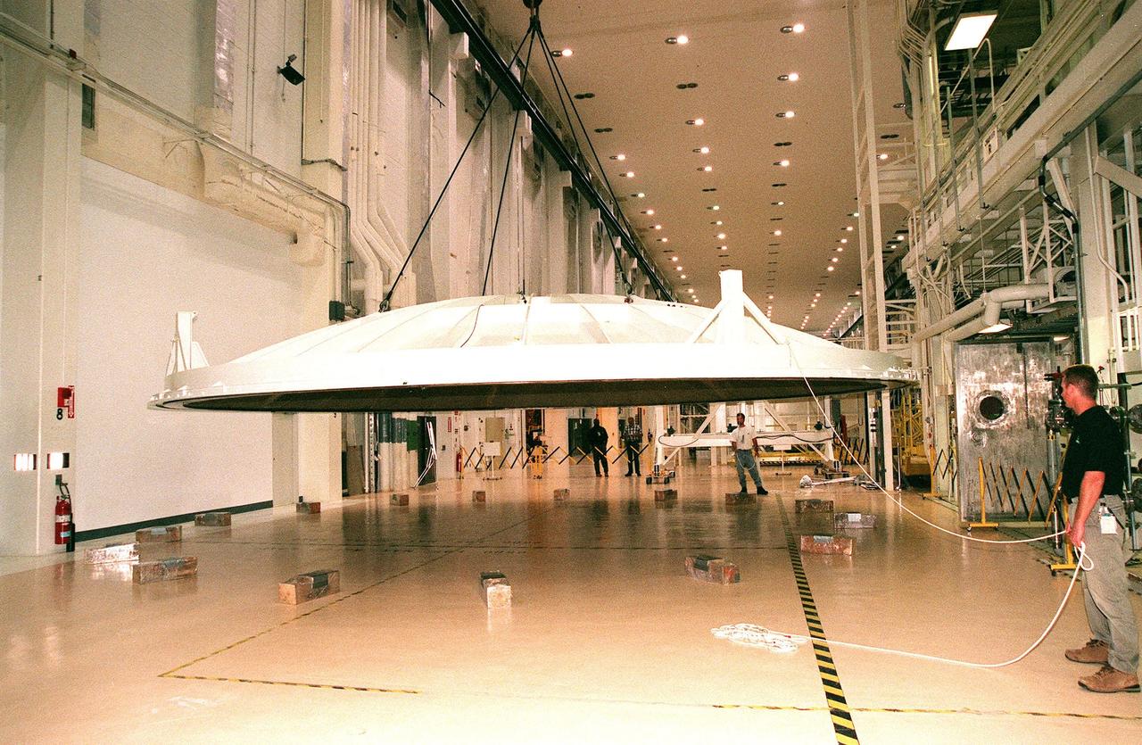
KENNEDY SPACE CENTER, FLA. -- An overhead crane lifts the saucer-like 27.5-ton lid of an altitude chamber in the Operations and Checkout Building high bay. The chamber was recently reactivated, after a 24-year hiatus, to perform leak tests on International Space Station pressurized modules at the launch site. Originally, two chambers were built to test Apollo Program flight hardware. They were last used in 1975 during the Apollo-Soyuz Test Project. After installation of new vacuum pumping equipment and controls, a new control room, and a new rotation handling fixture, the chamber again became operational in February 1999. The chamber, which is 33 feet in diameter and 50 feet tall, is constructed of stainless steel. The first module that will be tested for leaks is the U.S. Laboratory. No date has been determined for the test
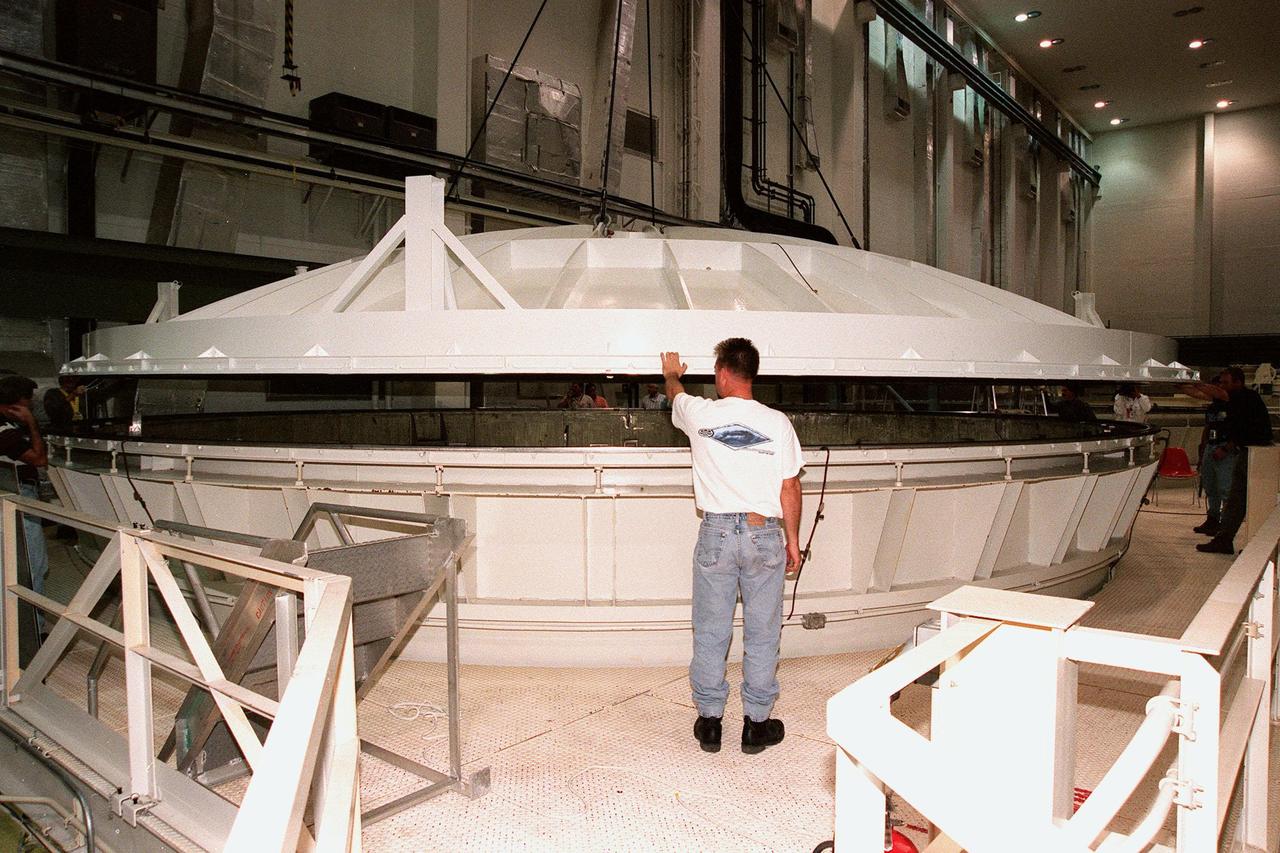
KENNEDY SPACE CENTER, FLA. -- Workers watch as the 27.5-ton lid is lowered onto the top of an altitude chamber in the Operations and Checkout Building high bay. The chamber was recently reactivated, after a 24-year hiatus, to perform leak tests on International Space Station pressurized modules at the launch site. Originally, two chambers were built to test Apollo Program flight hardware. They were last used in 1975 during the Apollo-Soyuz Test Project. After installation of new vacuum pumping equipment and controls, a new control room, and a new rotation handling fixture, the chamber again became operational in February 1999. The chamber, which is 33 feet in diameter and 50 feet tall, is constructed of stainless steel. The first module that will be tested for leaks is the U.S. Laboratory. No date has been determined for the test
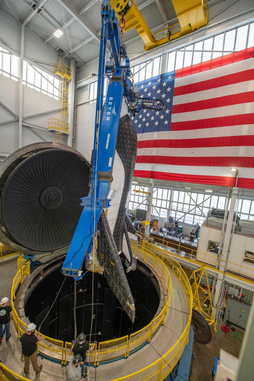
Sierra Space Dream Chaser space plane is lifted into the chamber at ISP (In Space Propulsion) facility, building 3211 at ATF (Armstrong Test Facility) for environmental testing. Once lowered into the test chamber, it will be exposed to the harsh cold conditions of space for extended periods of time.
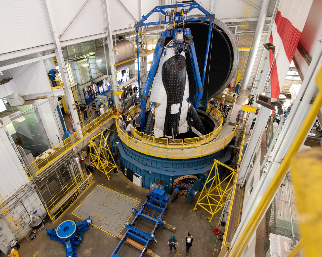
Sierra Space Dream Chaser space plane is lifted into the chamber at ISP (In Space Propulsion) facility, building 3211 at ATF (Armstrong Test Facility) for environmental testing. Once lowered into the test chamber, it will be exposed to the harsh cold conditions of space for extended periods of time.
Space Power Facility (SPF) - Test Chamber
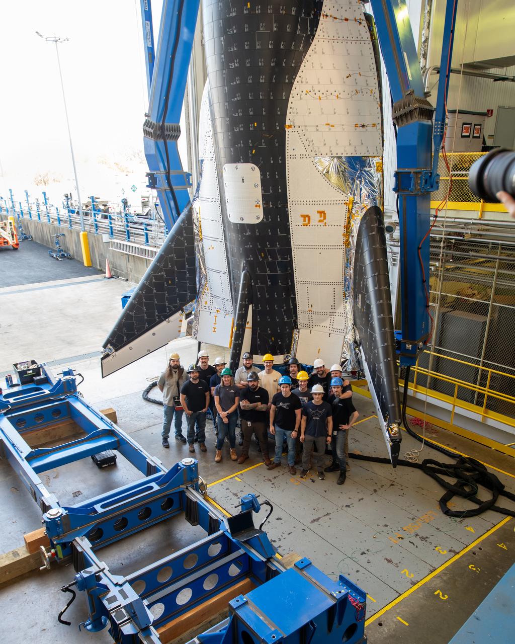
Group photo of the crew just before the critical lift of Dream Chaser into the chamber at ISP (In Space Propulsion) NASA GRC-ATF. Once lifted and lowered into the test chamber, it will be exposed to the harsh cold conditions of space for extended periods of time. Sierra Space Dream Chaser space plane will be lifted into the chamber at ISP (In Space Propulsion) facility, building 3211 at ATF (Armstrong Test Facility) for environmental testing
This video of the Perseverance rover's gDRT (Gaseous Dust Removal Tool) in action was taken during a test in a vacuum chamber at NASA's Jet Propulsion Laboratory in Southern California in August 2020. The tool fires 12-pounds-per-square-inch (about 83 kilopascal) puffs of nitrogen at the tailings and dust that cover a rock after it has been abraded by the rover. Five puffs are required per abrasion – one to vent the tanks and four to clear the abrasion. Animation available at https://photojournal.jpl.nasa.gov/catalog/PIA26578
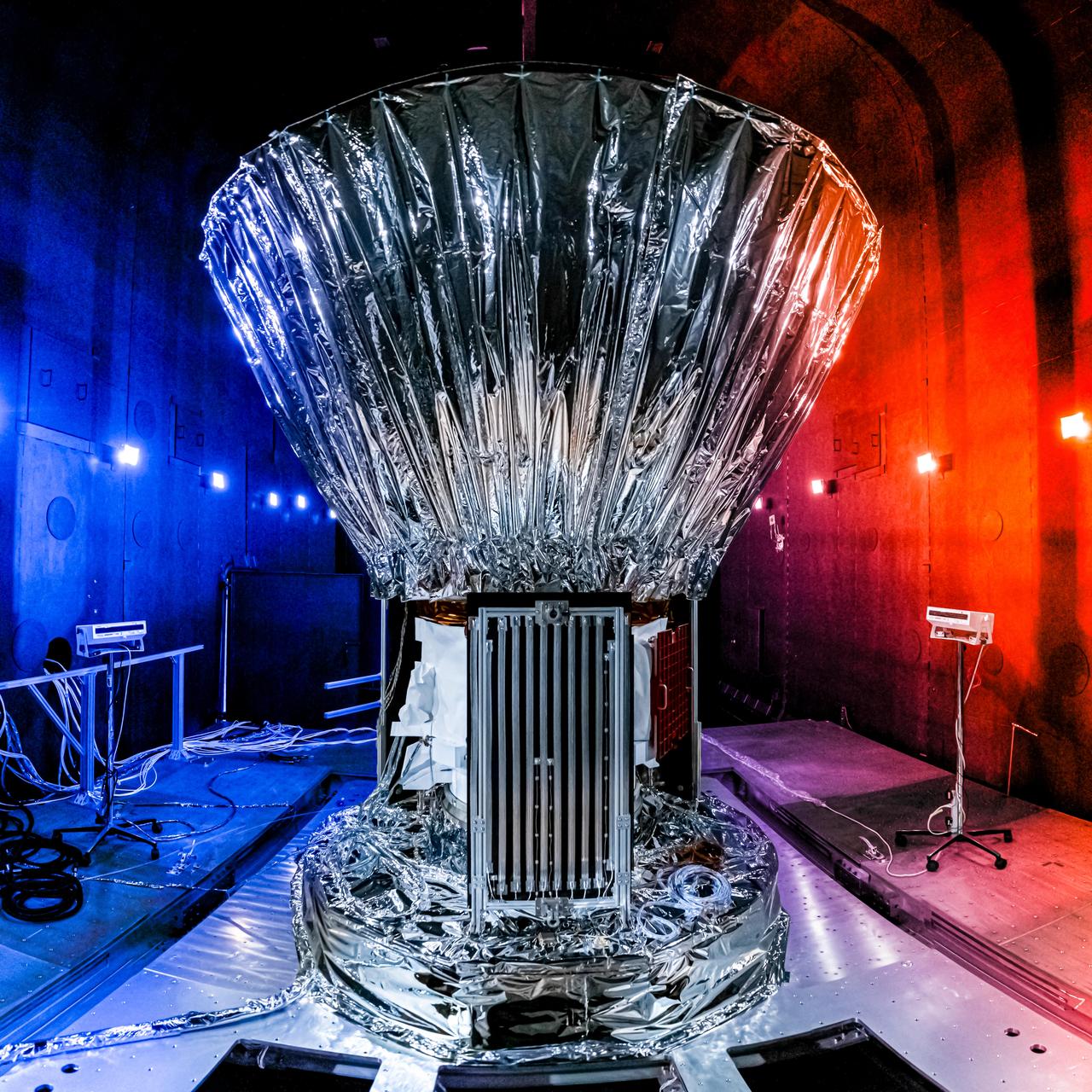
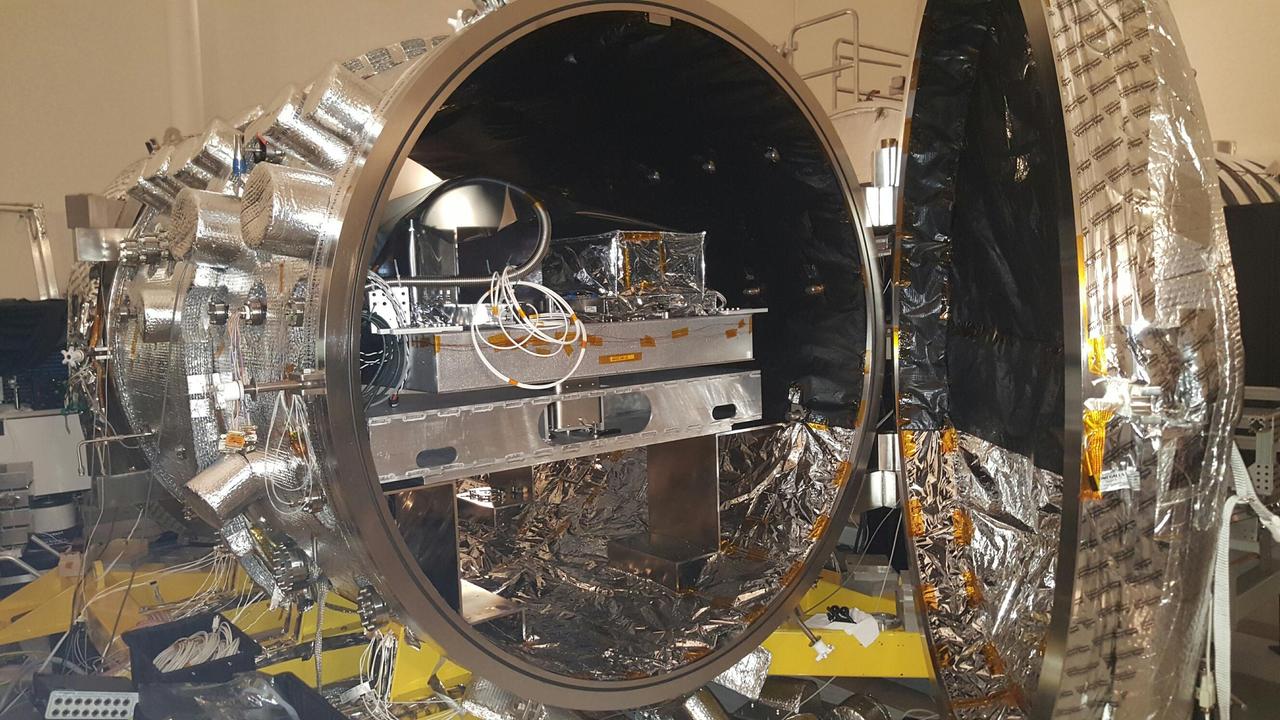
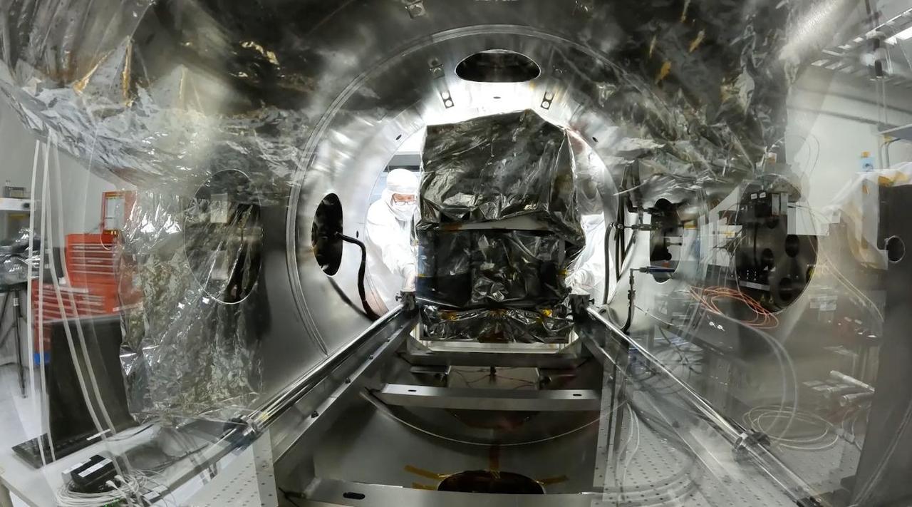
NASA's SPHEREx observatory is installed in the Titan Thermal Vacuum (TVAC) test Chamber at BAE Systems in Boulder, Colorado, in June 2024. As part of the test setup, the spacecraft and photon shield are covered in multilayer insulation and blankets and surrounded by ground support equipment. Short for Spectro-Photometer for the History of the Universe, Epoch of Reionization and Ices Explorer, SPHEREx will create a map of the cosmos like no other. Using a technique called spectroscopy to image the entire sky in 102 wavelengths of infrared light, SPHEREx will gather information about the composition of and distance to millions of galaxies and stars. With this map, scientists will study what happened in the first fraction of a second after the big bang, how galaxies formed and evolved, and the origins of water in planetary systems in our galaxy. https://photojournal.jpl.nasa.gov/catalog/PIA26541
KENNEDY SPACE CENTER, FLA. -- In the Operations and Checkout Building's high bay, the Rotation Handling Fixture (RHF), with a simulated module attached, is lowered by crane into the altitude chamber below during a test. Under normal operation, the RHF will hold a pressurized module intended for the International Space Station, depositing it into the altitude chamber for leak testing. The chamber was recently reactivated after a 24-year hiatus. Originally, two chambers were built to test Apollo Program flight hardware. They were last used in 1975 during the Apollo-Soyuz Test Project. In 1997, in order to increase the probability of successful missions aboard the ISS, NASA decided to perform leak tests on ISS pressurized modules at the launch site. After installation of new vacuum pumping equipment and controls, a new control room, and a new rotation and handling fixture, the chamber again became operational in February 1999. The chamber, which is 33 feet in diameter and 50 feet tall, is constructed of stainless steel. The rotation handling fixture is aluminum. The first module that will be tested for leaks is the U.S. Laboratory. No date has been determined for the test
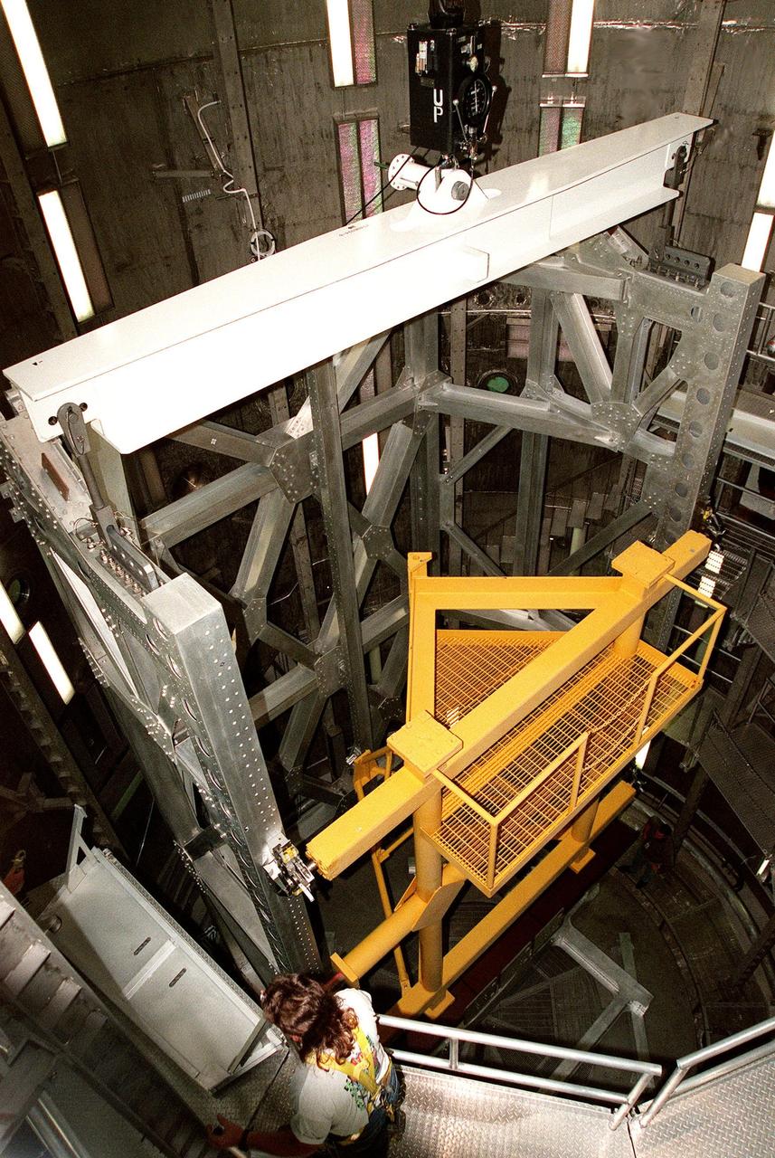
KENNEDY SPACE CENTER, FLA. -- In the Operations and Checkout Building's high bay, the Rotation Handling Fixture (RHF), with a simulated module attached, is viewed from above the altitude chamber into which it was lowered during a test. Under normal operation, the RHF will hold a pressurized module intended for the International Space Station, depositing it into the altitude chamber for leak testing. The chamber was recently reactivated after a 20-year hiatus. Originally, two chambers were built to test Apollo Program flight hardware. They were last used in 1975 during the Apollo-Soyuz Test Project. In 1997, in order to increase the probability of successful missions aboard the ISS, NASA decided to perform leak tests on ISS pressurized modules at the launch site. After installation of new vacuum pumping equipment and controls, a new control room, and a new rotation and handling fixture, the chamber again became operational in February 1999. The chamber, which is 33 feet in diameter and 50 feet tall, is constructed of stainless steel. The rotation handling fixture is aluminum. The first module that will be tested for leaks is the U.S. Laboratory. No date has been determined for the test
KENNEDY SPACE CENTER, FLA. -- Viewed from inside the altitude chamber in the Operations and Checkout Building's high bay, the Rotation Handling Fixture (RHF), with a simulated module attached, is lowered during a test. Under normal operation, the RHF will hold a pressurized module intended for the International Space Station, depositing it into the altitude chamber for leak testing. The chamber was recently reactivated after a 24-year hiatus. Originally, two chambers were built to test Apollo Program flight hardware. They were last used in 1975 during the Apollo-Soyuz Test Project. In 1997, in order to increase the probability of successful missions aboard the ISS, NASA decided to perform leak tests on ISS pressurized modules at the launch site. After installation of new vacuum pumping equipment and controls, a new control room, and a new rotation and handling fixture, the chamber again became operational in February 1999. The chamber, which is 33 feet in diameter and 50 feet tall, is constructed of stainless steel. The rotation handling fixture is aluminum. The first module that will be tested for leaks is the U.S. Laboratory. No date has been determined for the test
Inside a thermal vacuum at Lockheed Martin Space Systems, Denver, technicians prepared NASA Phoenix Mars Lander for environmental testing
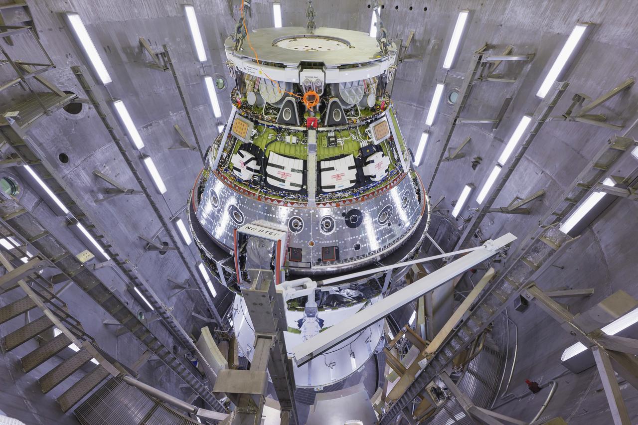
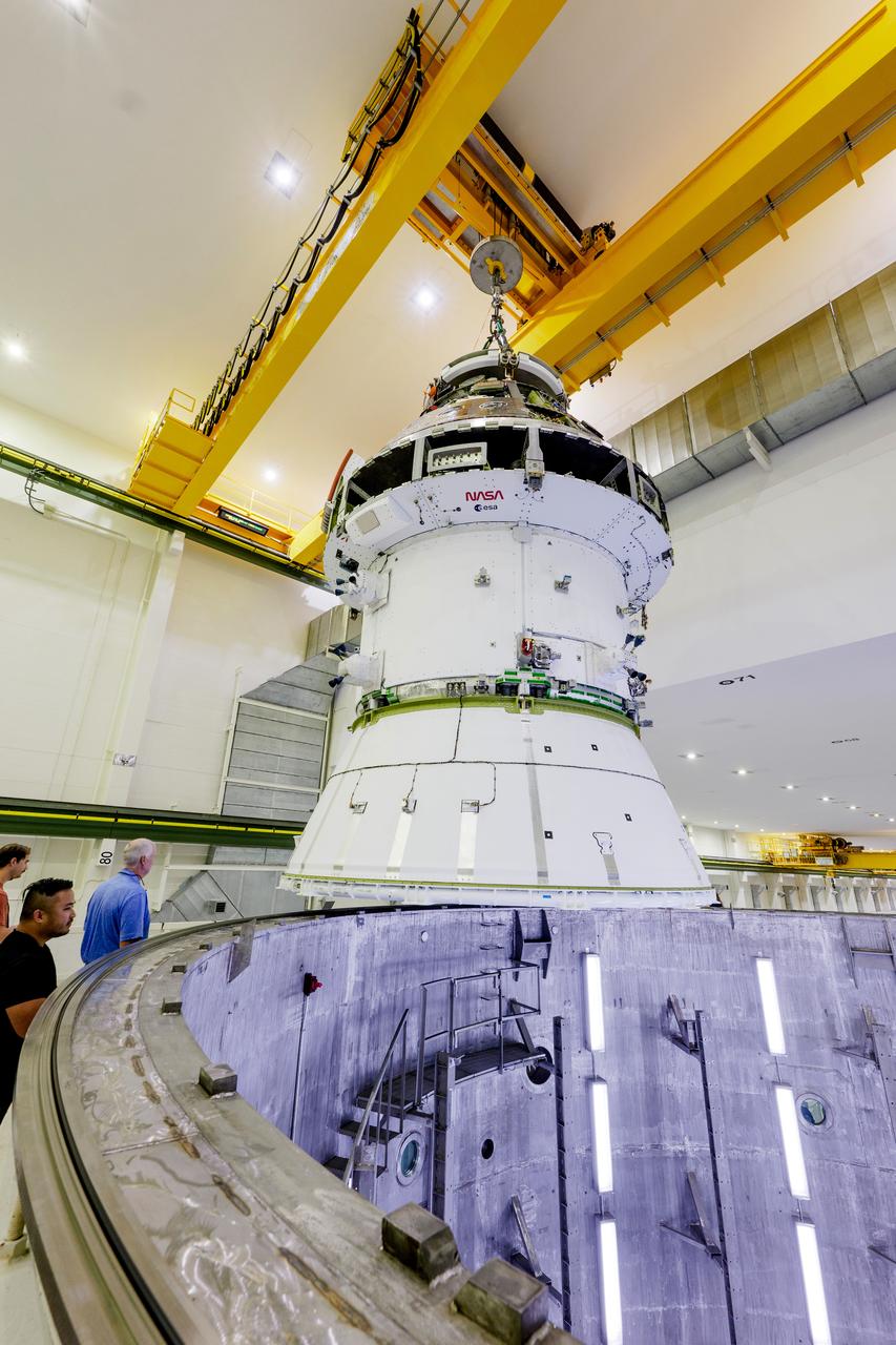
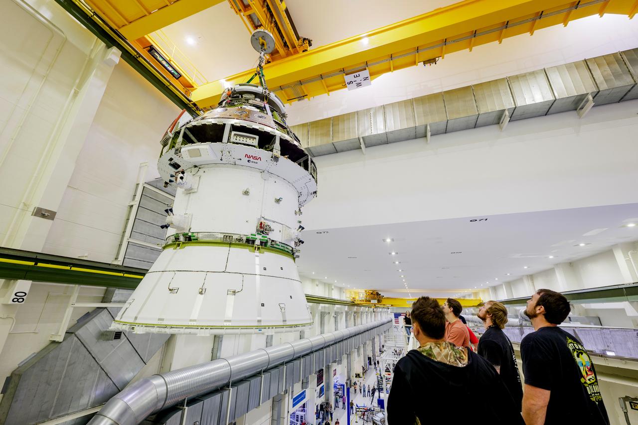
Technicians used a 30-ton crane to lift NASA’s Orion spacecraft on Friday, June 28, 2024, from the Final Assembly and System Testing (FAST) cell to the altitude chamber inside the Neil A. Armstrong Operations and Checkout building at NASA’s Kennedy Space Center in Florida. The spacecraft, which will be used for the Artemis II mission to orbit the Moon, underwent leak checks and end-to-end performance verification of the vehicle’s subsystems.

Technicians used a 30-ton crane to lift NASA’s Orion spacecraft on Friday, June 28, 2024, from the Final Assembly and System Testing (FAST) cell to the altitude chamber inside the Neil A. Armstrong Operations and Checkout building at NASA’s Kennedy Space Center in Florida. The spacecraft, which will be used for the Artemis II mission to orbit the Moon, underwent leak checks and end-to-end performance verification of the vehicle’s subsystems.
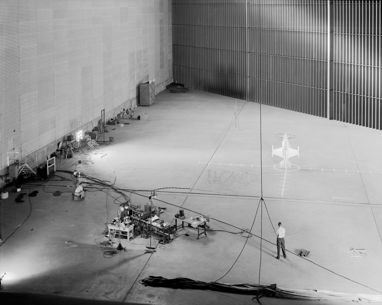
Wide shot of 40x 80 wind tunnel settling chamber with Lockheed XFV-1 model. Project engineer Mark Kelly (not shown). Remote controlled model flown in the settling chamber of the 40x80 wind tunnel. Electric motors in the model, controlled the counter-rotating propellers to test vertical takeoff. Test no. 71
THE 2012 CIF RADIATOR FACILITY WITH A 2012 TEST ARTICLE AS IT WOULD BE POSITIONED IN THE CHAMBER.-
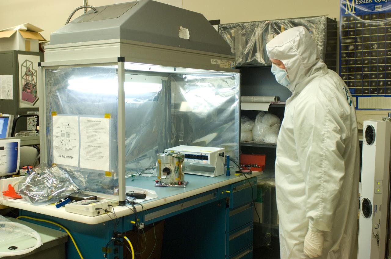
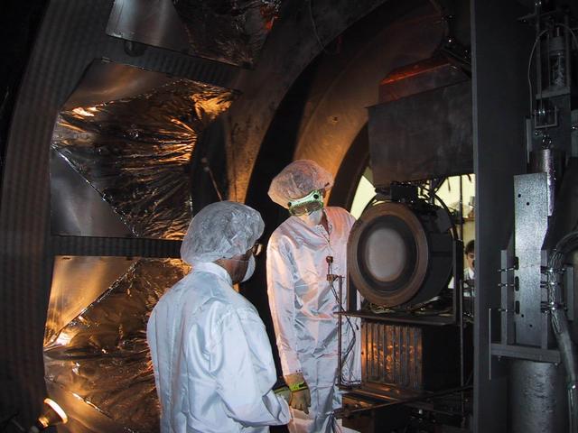
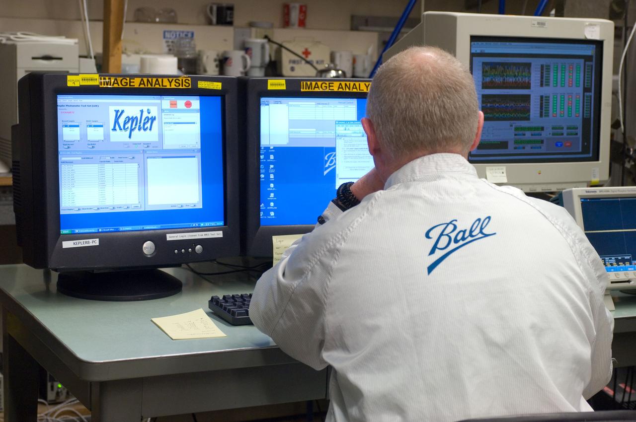
Kepler project; technicians from Ball Aerospace work on and in the test chamber assembled at Nasa Ames Research center testing components
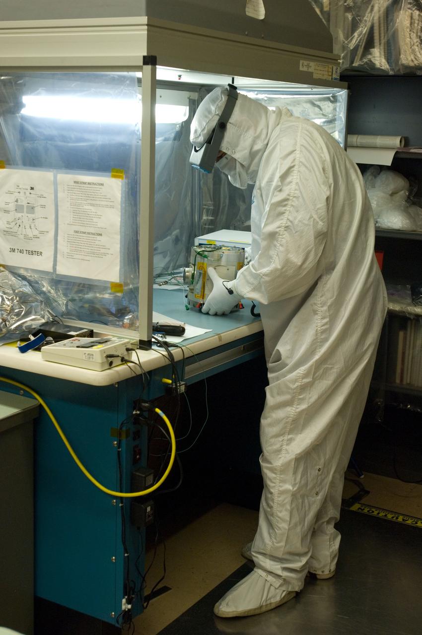
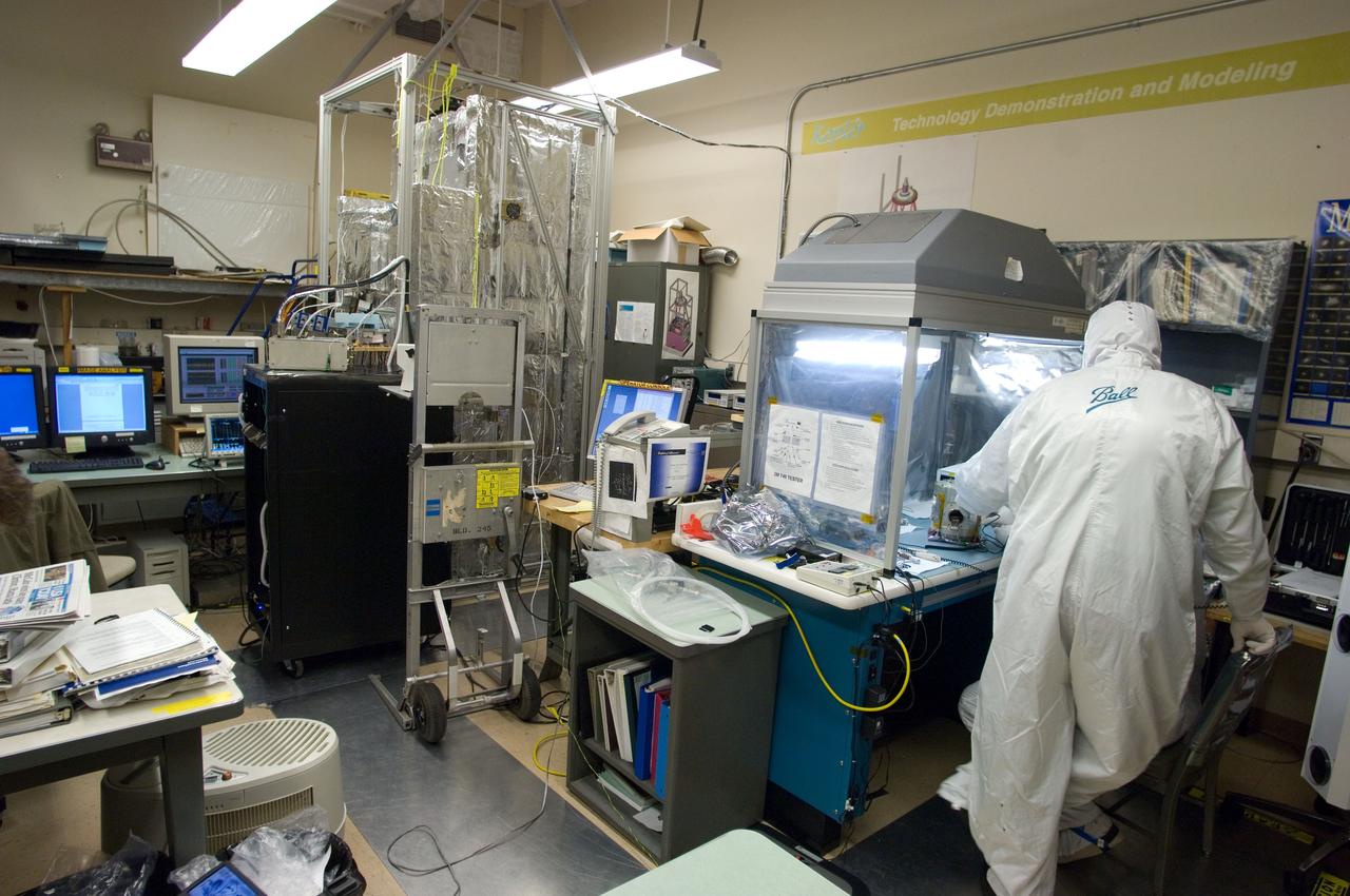
Kepler project; technicians from Ball Aerospace work on and in the test chamber assembled at Nasa Ames Research center testing components
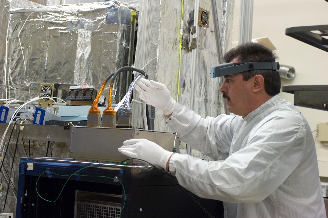
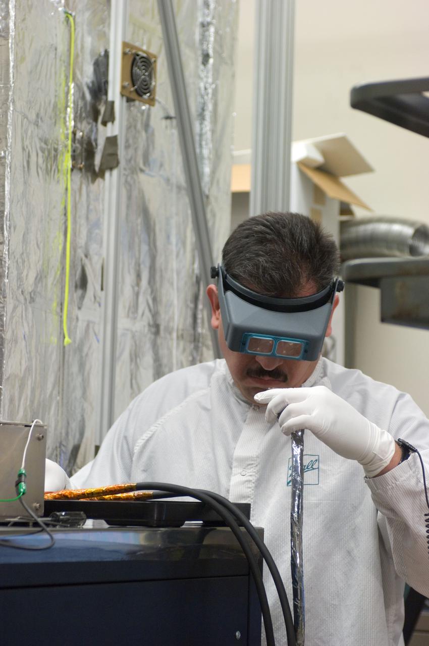
Kepler project; technicians from Ball Aerospace work on and in the test chamber assembled at Nasa Ames Research center testing components
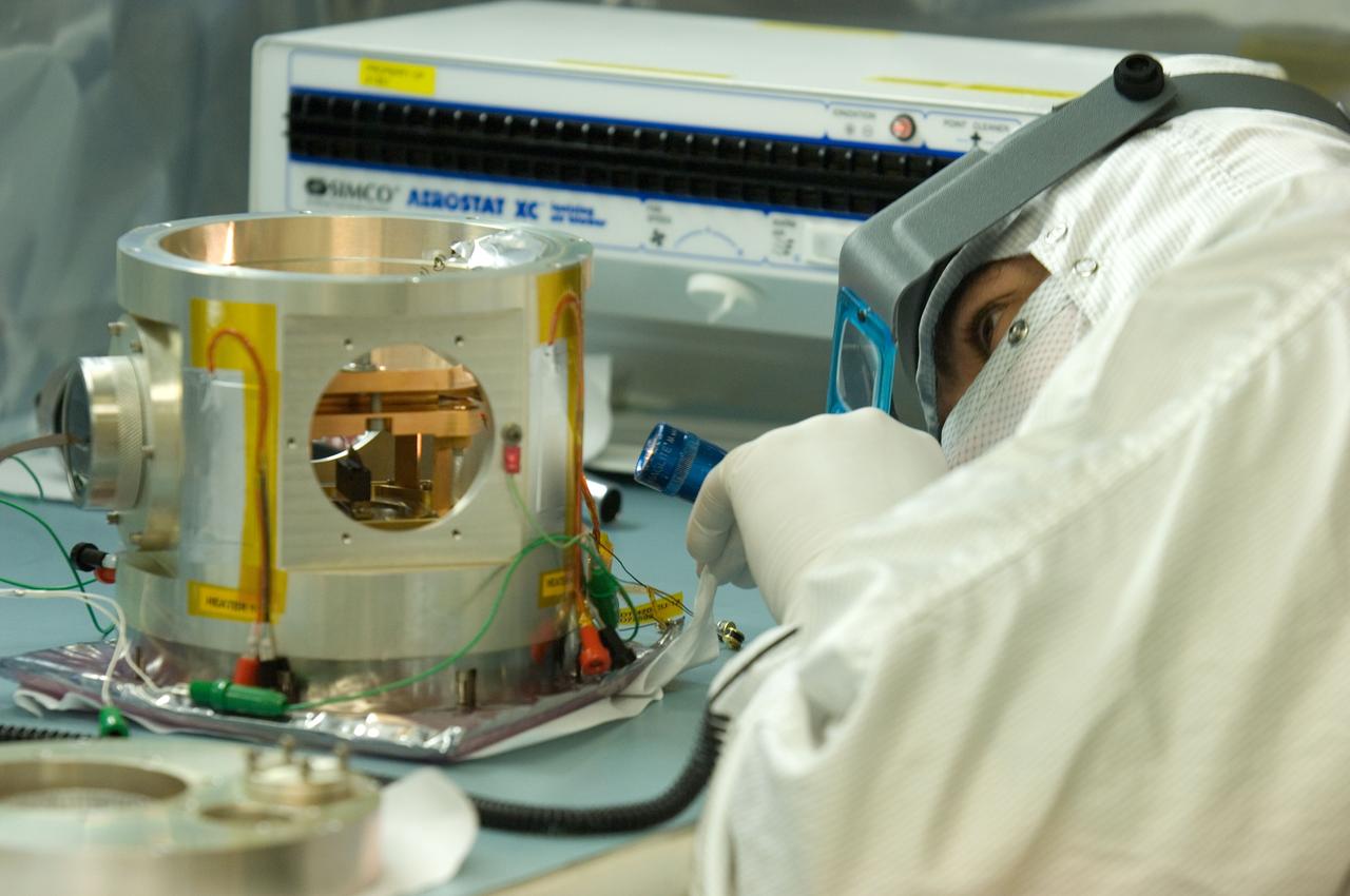
Kepler project; technicians from Ball Aerospace work on and in the test chamber assembled at Nasa Ames Research center testing components
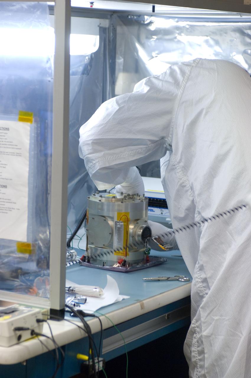
Kepler project; technicians from Ball Aerospace work on and in the test chamber assembled at Nasa Ames Research center testing components
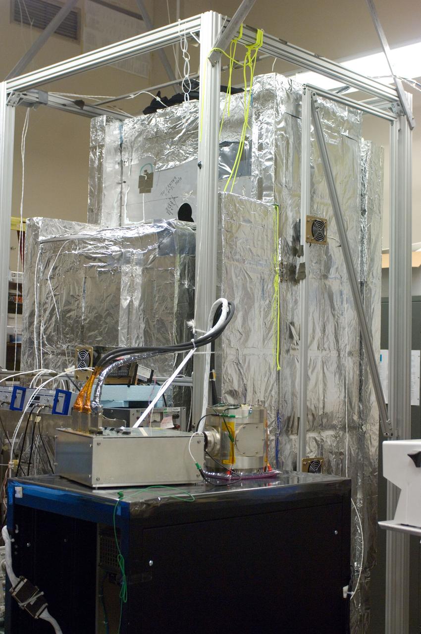
Kepler project; technicians from Ball Aerospace work on and in the test chamber assembled at Nasa Ames Research center testing components
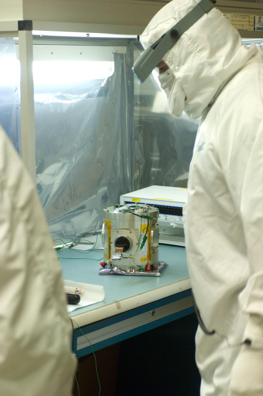
Kepler project; technicians from Ball Aerospace work on and in the test chamber assembled at Nasa Ames Research center testing components
Kepler project; technicians from Ball Aerospace work on and in the test chamber assembled at Nasa Ames Research center testing components
Kepler project; technicians from Ball Aerospace work on and in the test chamber assembled at Nasa Ames Research center testing components
Kepler project; technicians from Ball Aerospace work on and in the test chamber assembled at Nasa Ames Research center testing components