
Trajectory oriented operatons with limited delegation simulation in Airspace Operations Lab N-262 rm-270 with Jeff Homola

Trajectory oriented operatons with limited delegation simulation in Airspace Operations Lab N-262 rm-270 with Jeff Homola

Trajectory oriented operatons with limited delegation simulation in Airspace Operations Lab N-262 rm-270 with Todd Callantine

Trajectory oriented operatons with limited delegation simulation in Airspace Operations Lab N-262 rm-270 with Todd Callantine and Tom Prevot
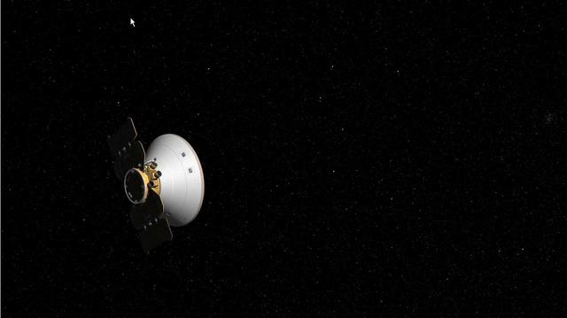
This artist animation shows NASA Phoenix Mars Lander adjusting its course to Mars, an event called a trajectory correction maneuver.
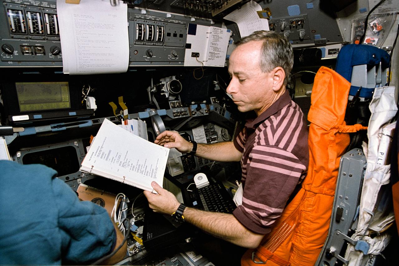
STS064-22-024 (9-20 Sept. 1994) --- With a manual and lap top computer in front of him, astronaut Carl J. Meade, STS-64 mission specialist, supports operations with the Trajectory Control Sensor (TCS) aboard the Earth-orbiting space shuttle Discovery. For this exercise, Meade temporarily mans the pilot's station on the forward flight deck. The TCS is the work of a team of workers at NASA's Johnson Space Center. Data gathered during this flight was expected to prove valuable in designing and developing a sensor for use during the rendezvous and mating phases of orbiter missions to the space station. For this demonstration, the Shuttle Pointed Autonomous Research Tool for Astronomy 201 (SPARTAN 201) was used as the target vehicle during release and retrieval operations. Photo credit: NASA or National Aeronautics and Space Administration
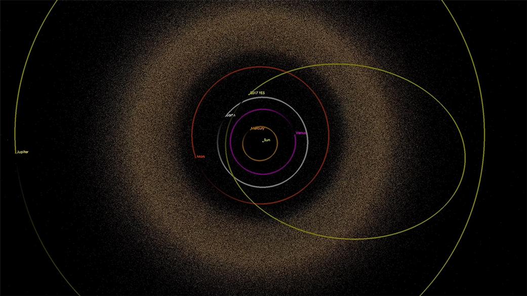
Artist's illustration of the trajectory of asteroid 2017 YE5 through the solar system. At its closest approach to Earth, the asteroid came to within 16 times the distance between Earth and the moon. A movie is available at https://photojournal.jpl.nasa.gov/catalog/PIA22560
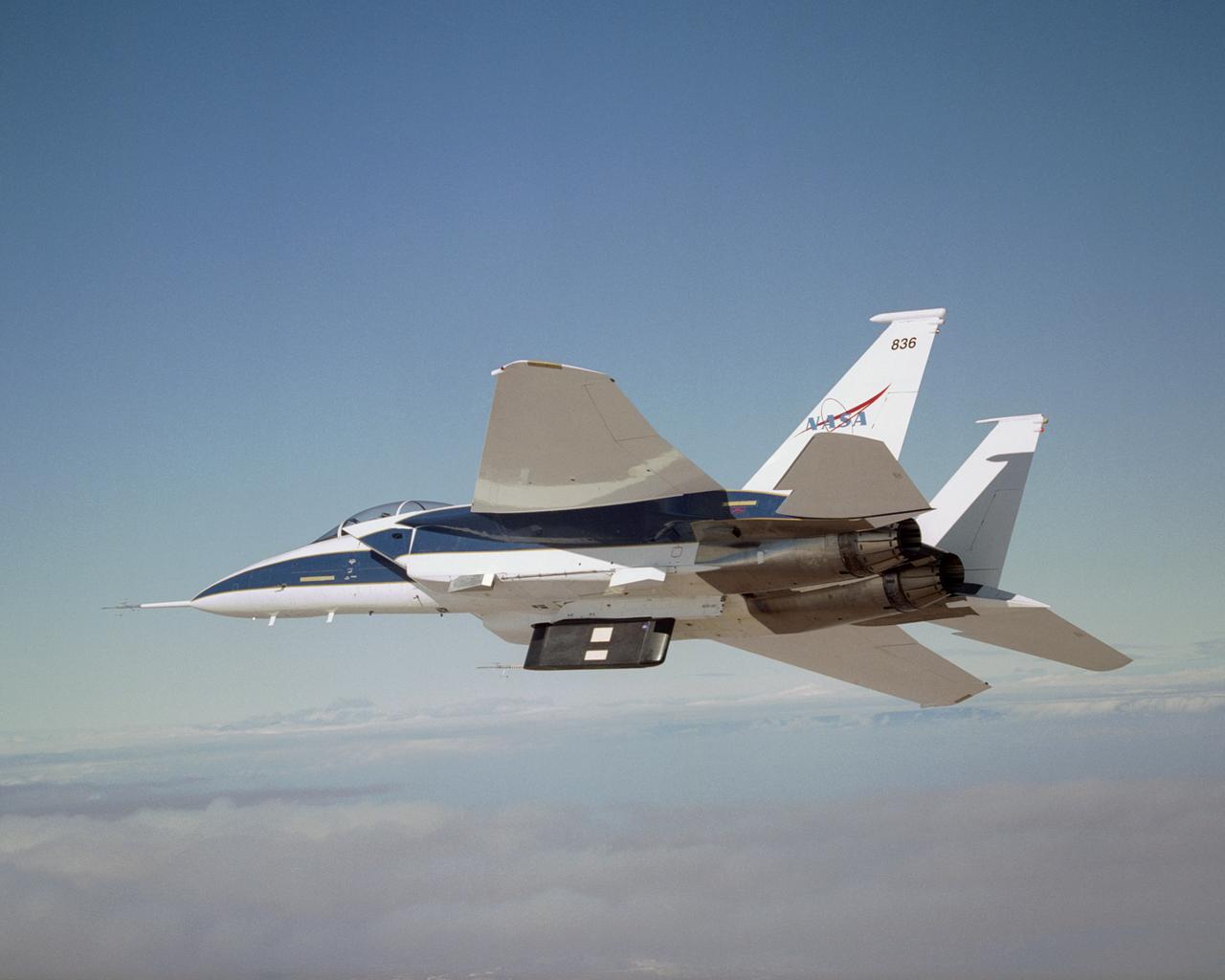
Two panels of Space Shuttle TPS insulation were mounted on the flight test fixture underneath NASA's F-15B during the Lifting Foam Trajectory flight test series.
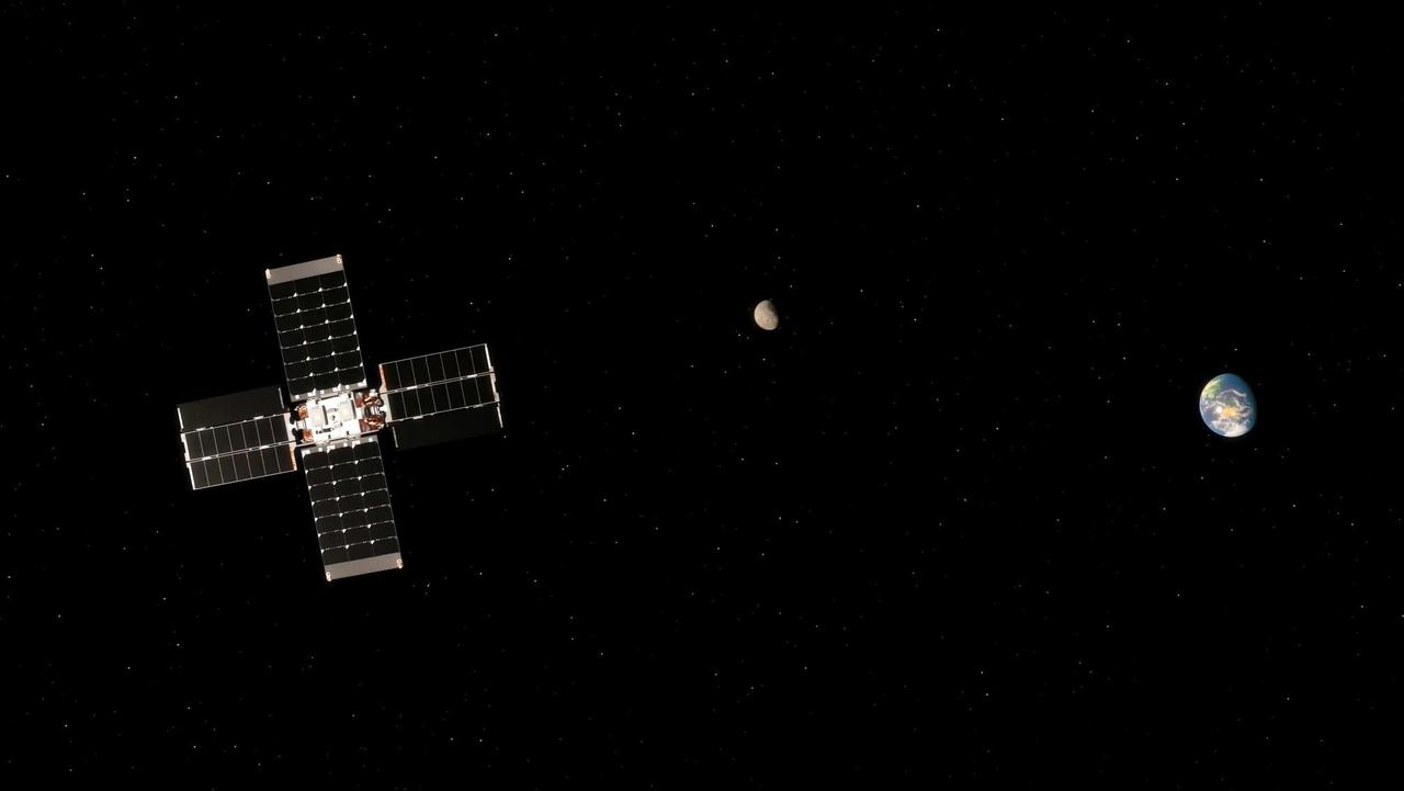
This illustration shows NASA's Lunar Flashlight carrying out a trajectory correction maneuver with the Moon and Earth in the background. Powered by the small satellite's four thrusters, the maneuver is needed to reach lunar orbit. Lunar Flashlight launched Nov. 30, 2022, and will take about four months to reach its science orbit to seek out surface water ice in the darkest craters of the Moon's South Pole. A technology demonstration, the small satellite, or SmallSat, will use a reflectometer equipped with four lasers that emit near-infrared light in wavelengths readily absorbed by surface water ice. To achieve the mission's goals with the satellite's limited amount of propellent, Lunar Flashlight will employ an energy-efficient near-rectilinear halo orbit, taking it within 9 miles (15 kilometers) of the lunar South Pole and 43,000 miles (70,000 kilometers) away at its farthest point. Only one other spacecraft has employed this type of orbit: NASA's Cislunar Autonomous Positioning System Technology Operations and Navigation Experiment (CAPSTONE) mission, which launched in June 2022. https://photojournal.jpl.nasa.gov/catalog/PIA25258
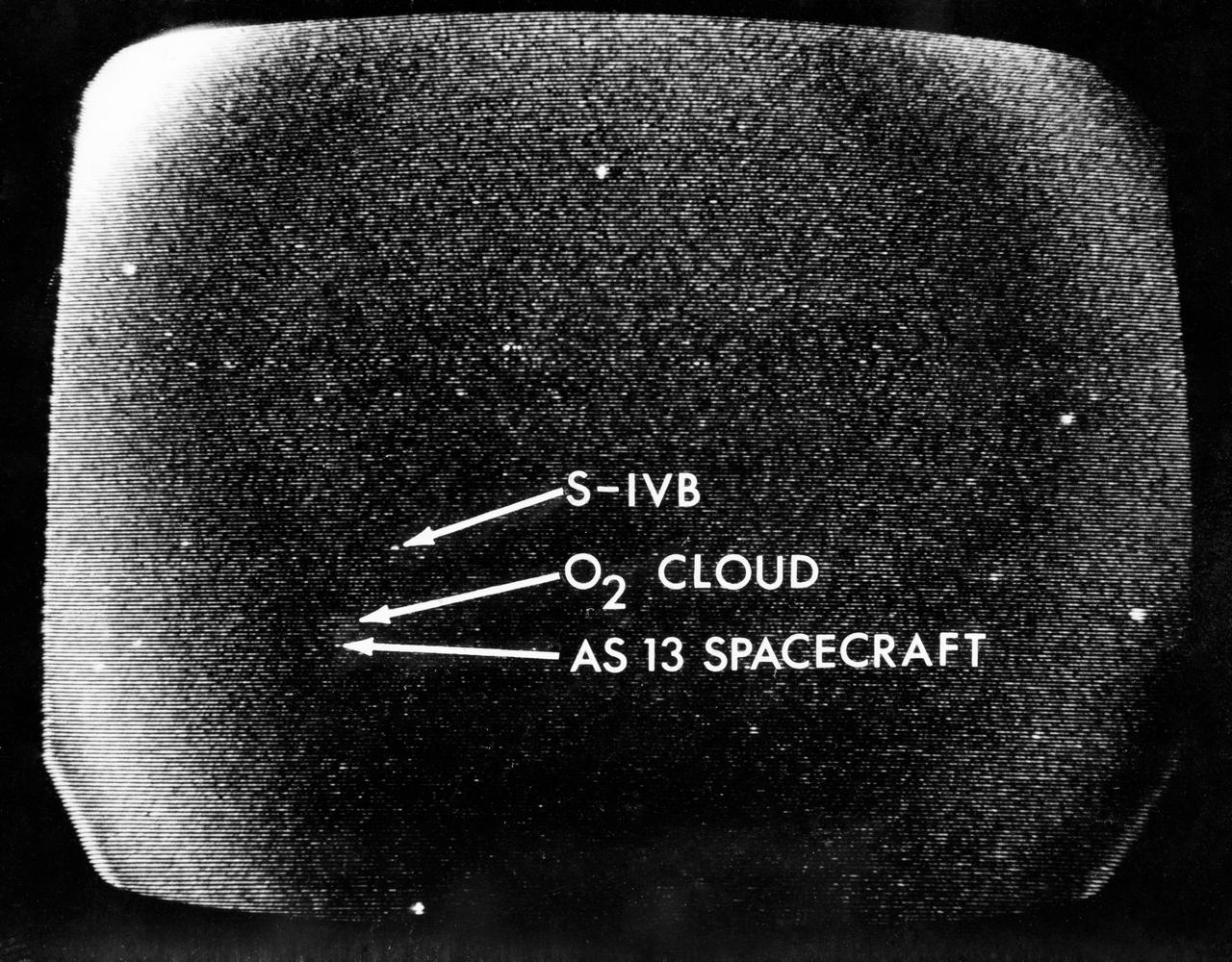
S70-34857 (13 April 1970) --- A telescopic photograph showing the Apollo 13 spacecraft in trans-lunar trajectory in the distant sky. Arrows point to the spacecraft, to the oxygen cloud, and to the expended Saturn V third stage. Apollo 13 was tracked at the Manned Spacecraft Center (MSC) using a 16 inch Schmidt-Cassegrain telescope with an IO television camera with an S-20 type IO tube, mounted in place of the eyepiece. The TV camera information is stored first on a data disc and played back on a viewing monitor from which this photograph was taken.

NASA Voyager 2 post-encounter view of Neptune south pole as the spacecraft sped away on a southward trajectory.
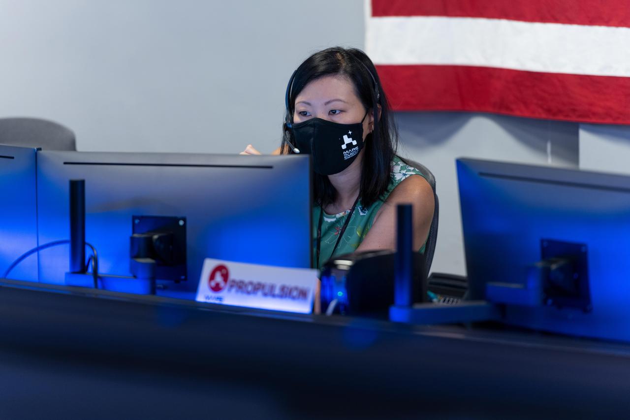
Propulsion Lead Rebekah Lam participates in Perseverance's second trajectory correction maneuver at NASA's Jet Propulsion Laboratory in Southern California. https://photojournal.jpl.nasa.gov/catalog/PIA24194
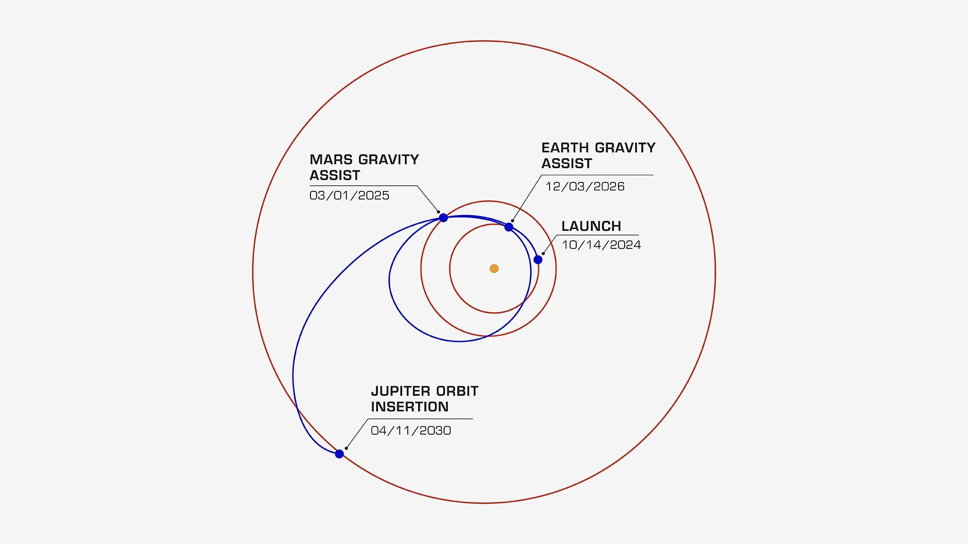
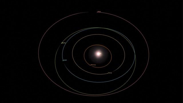
On its journey to the Jupiter system, NASA's Europa Clipper will take a path that swings past Mars, then Earth, using the gravity of each planet as a slingshot to boost the spacecraft's speed. All told, the journey will take about 5½ years, covering a distance of about 1.8 billion miles (2.9 billion kilometers). In this diagram, the orbits of Jupiter, Mars, and Earth are shown as concentric rings. Europa Clipper's launch period begins on Oct. 10, 2024. If the spacecraft launches on a later date, the timing of its Mars and Earth gravity assist maneuvers will shift. For all liftoff dates within the launch period, however, the spacecraft is scheduled to begin orbiting Jupiter on April 11, 2030. Then it will begin its investigation of the gas giant's icy moon Europa. Europa Clipper's three main science objectives are to determine the thickness of the moon's icy shell and its interactions with the ocean below, to investigate its composition, and to characterize its geology. The mission's detailed exploration of Europa will help scientists better understand the astrobiological potential for habitable worlds beyond our planet. Managed by Caltech in Pasadena, California, NASA's Jet Propulsion Laboratory leads the development of the Europa Clipper mission in partnership with APL for NASA's Science Mission Directorate in Washington. APL designed the main spacecraft body in collaboration with JPL and NASA's Goddard Space Flight Center in Greenbelt, Maryland, NASA's Marshall Space Flight Center in Huntsville, Alabama, and Langley Research Center in Hampton, Virginia. The Planetary Missions Program Office at Marshall executes program management of the Europa Clipper mission. NASA's Launch Services Program, based at Kennedy, manages the launch service for the Europa Clipper spacecraft, which will launch on a SpaceX Falcon Heavy rocket from Launch Complex 39A at Kennedy. https://photojournal.jpl.nasa.gov/catalog/PIA26435
This animation illustrates the orbit path of NASA Stardust spacecraft.
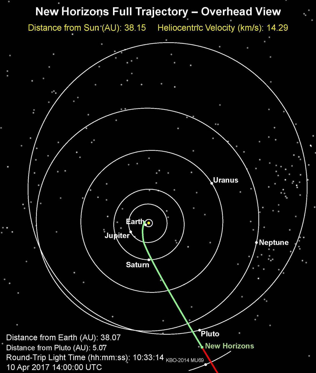
This is an overhead view of NASA's New Horizons full trajectory; the spacecraft has entered a hibernation phase on April 7 that will last until early September. The full article is available at https://photojournal.jpl.nasa.gov/catalog/PIA21589
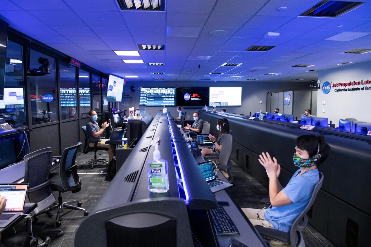
The Mars 2020 navigation team celebrates Perseverance's nominal, or successful, trajectory correction maneuver in the Mission Support Area at NASA's Jet Propulsion Laboratory in Southern California. https://photojournal.jpl.nasa.gov/catalog/PIA24192

This animation illustrates the modeled trajectories of particles that were ejected from Bennu's surface on Jan. 19, 2019. After ejecting from the asteroid's surface, the particles either briefly orbited Bennu and fell back to its surface or escaped from Bennu and into space. Animation available at https://photojournal.jpl.nasa.gov/catalog/PIA23555
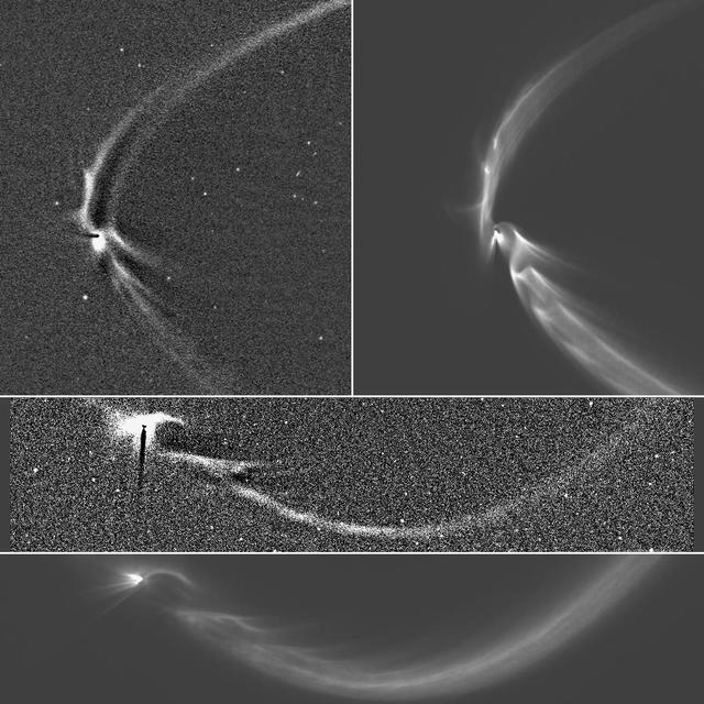
This collage of NASA Cassini spacecraft images and computer simulations shows how long, sinuous features from Enceladus can be modeled by tracing the trajectories of tiny, icy grains ejected from the moon south polar geysers.

Flight Director Matt Smith studies the data during the second post-launch trajectory correction maneuver during Perseverance's cruise to Mars. The team is in the Mission Support Area at NASA's Jet Propulsion Laboratory in Southern California. https://photojournal.jpl.nasa.gov/catalog/PIA24195

Matt Smith, flight director for the second Mars 2020 mission trajectory correction maneuver (TCM-2), studying the screens at NASA's Jet Propulsion Laboratory in Southern California. TCMs are a series of planned adjustments to put the rover on the correct path to land on Mars. https://photojournal.jpl.nasa.gov/catalog/PIA24193
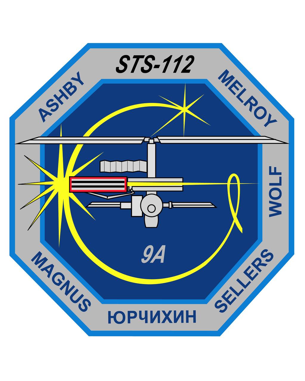
The STS-112 emblem symbolizes the ninth assembly mission (9A) to the International Space Station (ISS), the flight designed to deliver and install the Starboard 1 (S1) Truss segment. The emblem depicts the ISS from the viewpoint of a departing Shuttle, with the newly installed S1 truss outlined in red. A gold trail represents a portion of the Shuttle rendezvous trajectory. Where the trajectory meets the ISS, a nine-pointed star represents the 6 shuttle and 3 ISS crew members who together completed the S1 truss installation. The trajectory continues beyond the ISS, ending in a 6 pointed star representing the Atlantis STS-112 crew of six, whose names appear around the border.
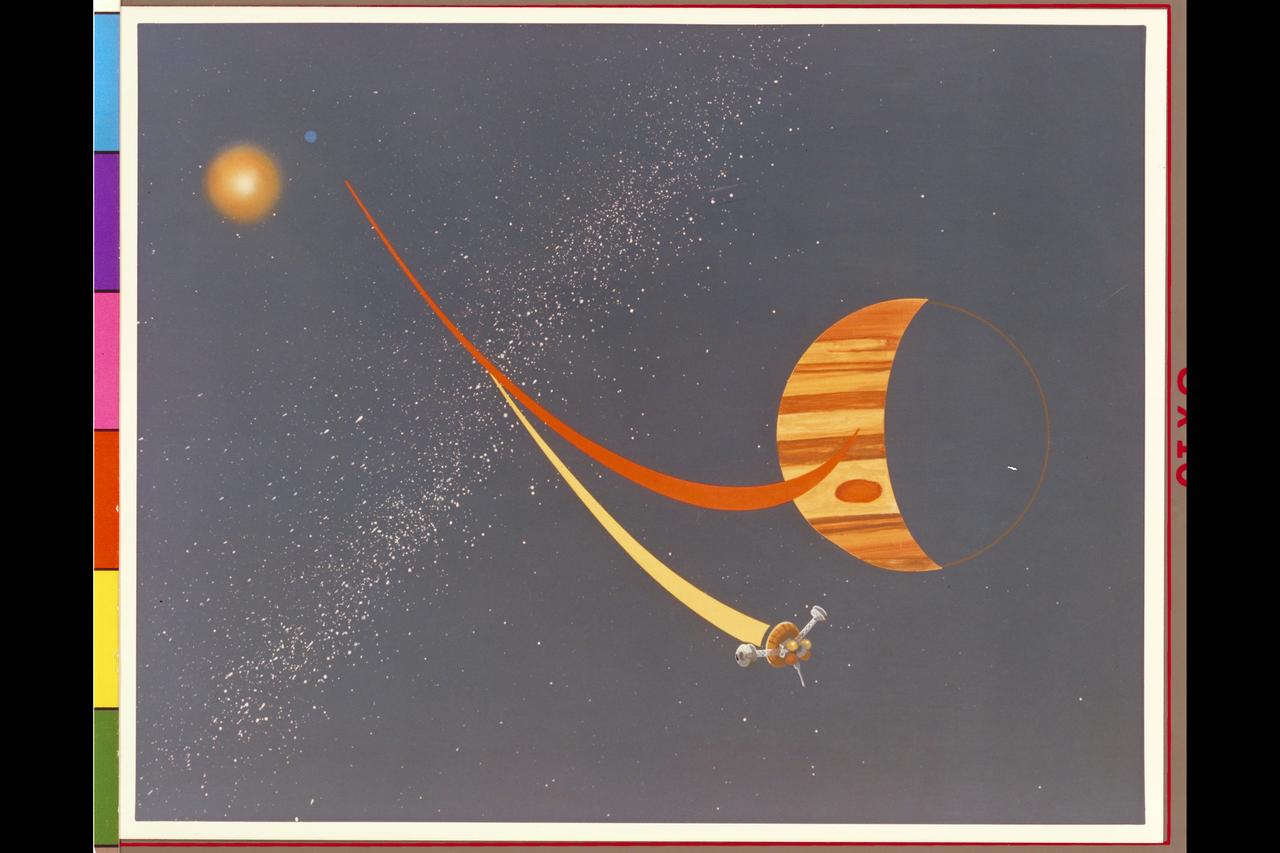
Pioneer Galileo mission trajectory artwork (ref: McDonnell Douglas May, 77 # D4C-117575-4)
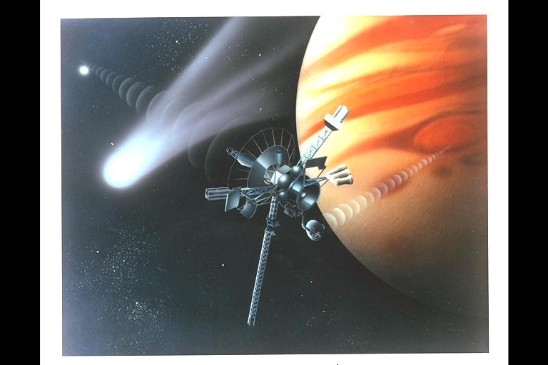
Pioneer Galileo mission trajectory artwork depicting radio signal from Earth to spacecraft to planet and comet crossing spacecrafts' orbit
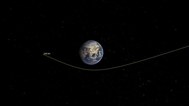
This illustration shows asteroid 2020 QG's trajectory bending during its close approach to Earth. The asteroid is the closest known non-impacting asteroid ever detected. The asteroid passed by 1,830 miles (2,945 kilometers) above the southern Indian Ocean on Sunday, Aug. 16 at 12:08 a.m. EDT (Saturday, Aug. 15 at 9:08 p.m. PDT). Movie available at https://photojournal.jpl.nasa.gov/catalog/PIA24037
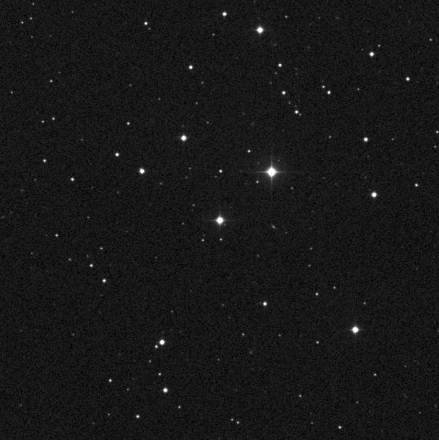
The image taken by the Oschin Schmidt Telescope, shows the star AC +79 3888, also known as Gliese 445. NASA Voyager 1 spacecraft, which is on a trajectory out of our solar system, is headed toward an encounter with AC +79 3888 circled in red.
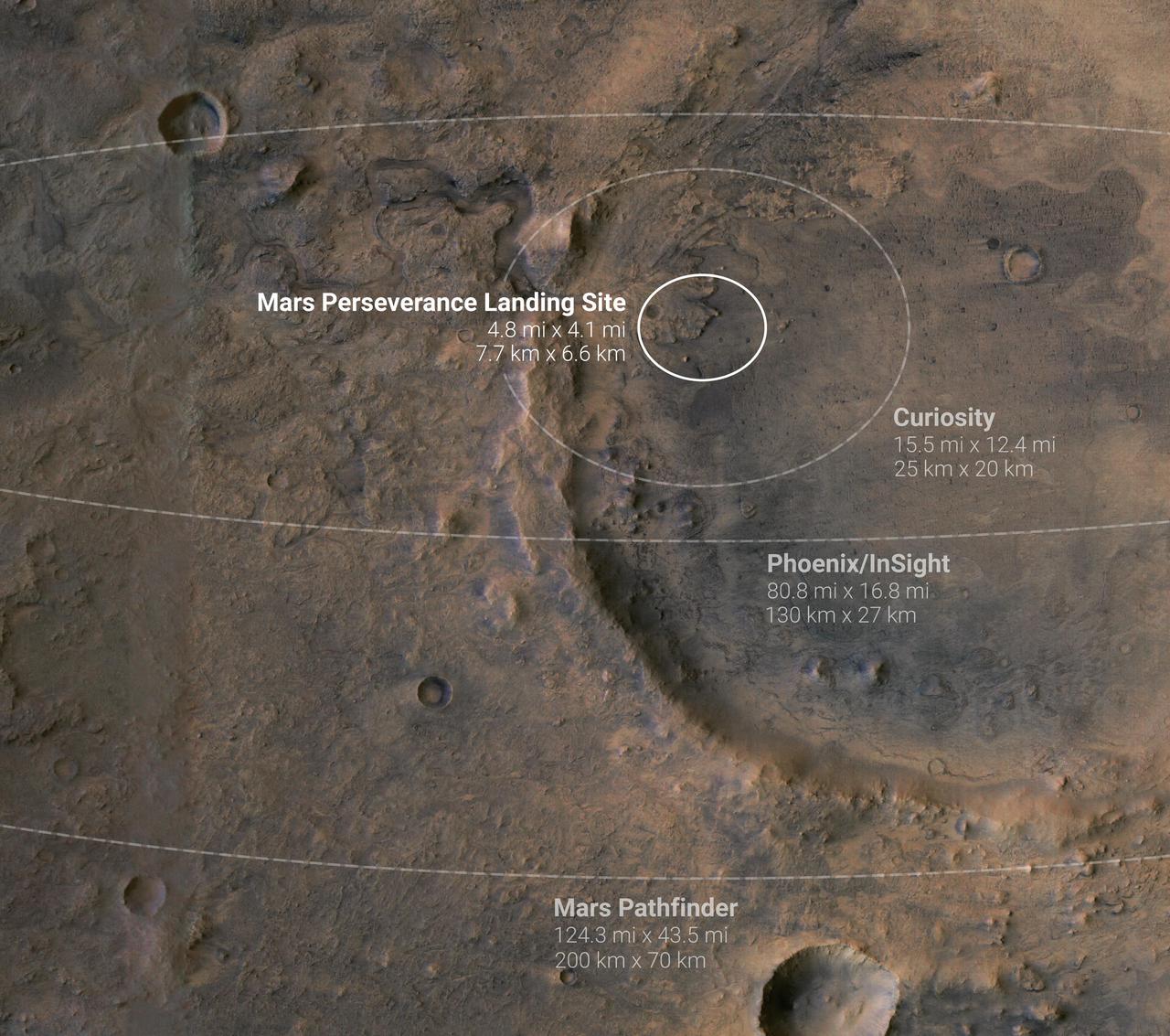
This annotated image shows landing ellipses for five NASA missions to Mars. A landing ellipse is the region within which a probe is expected to land based on its trajectory as it approaches the planet. A smaller landing ellipse means engineers have created a more precise model of the probe's expected trajectory. The four ellipses shown here are for the Perseverance Mars rover, Curiosity Mars rover, InSight Mars lander, Phoenix lander, and Mars Pathfinder probe. https://photojournal.jpl.nasa.gov/catalog/PIA24377
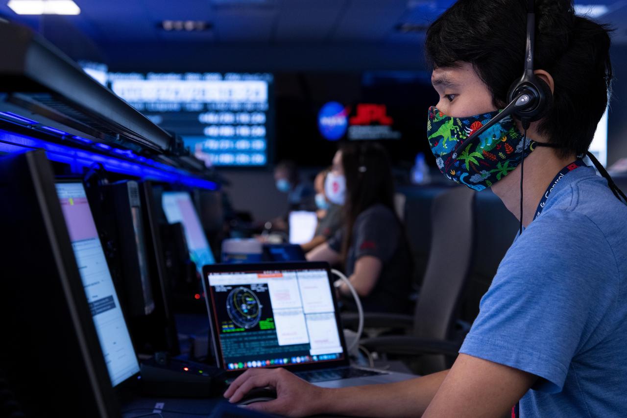
Attitude Control Systems lead Chris Pong donned a dinosaur-themed mask for his participation in the Mars 2020 mission's second trajectory correction maneuver at NASA's Jet Propulsion Laboratory in Southern California. The navigation team successfully sent commands to the spacecraft to adjust its flight path during its long cruise to Mars. https://photojournal.jpl.nasa.gov/catalog/PIA24191
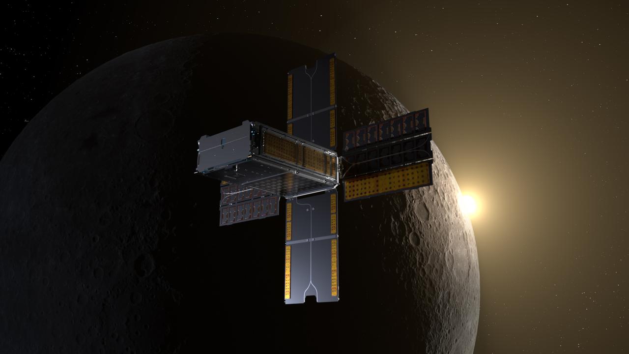
BioSentinel spacecraft enters a lunar flyby trajectory into a heliocentric orbit. BioSentinel will detect and measure the impact of space radiation on living organisms over long durations beyond low-Earth orbit (LEO). Illustration by Daniel Rutter.
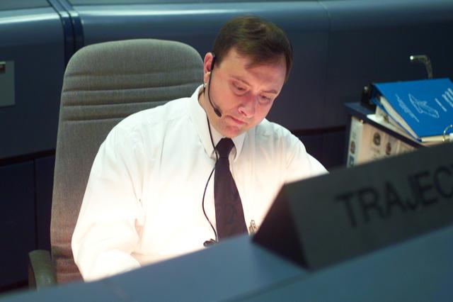
JSC2001-E-25391 (17 August 2001) --- Darrin Leleux, STS-105 trajectory officer, studies data at his console in the shuttle flight control room (WFCR) in Houston’s Mission Control Center (MCC).

BioSentinel spacecraft enters a lunar flyby trajectory into a heliocentric orbit. BioSentinel will detect and measure the impact of space radiation on living organisms over long durations beyond low-Earth orbit (LEO). Illustration by Daniel Rutter.
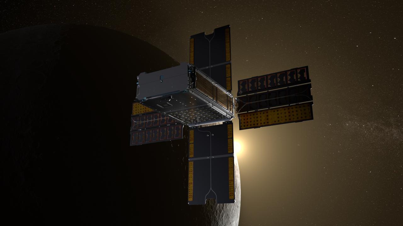
BioSentinel spacecraft enters a lunar flyby trajectory into a heliocentric orbit. BioSentinel will detect and measure the impact of space radiation on living organisms over long durations beyond low-Earth orbit (LEO). Illustration by Daniel Rutter.
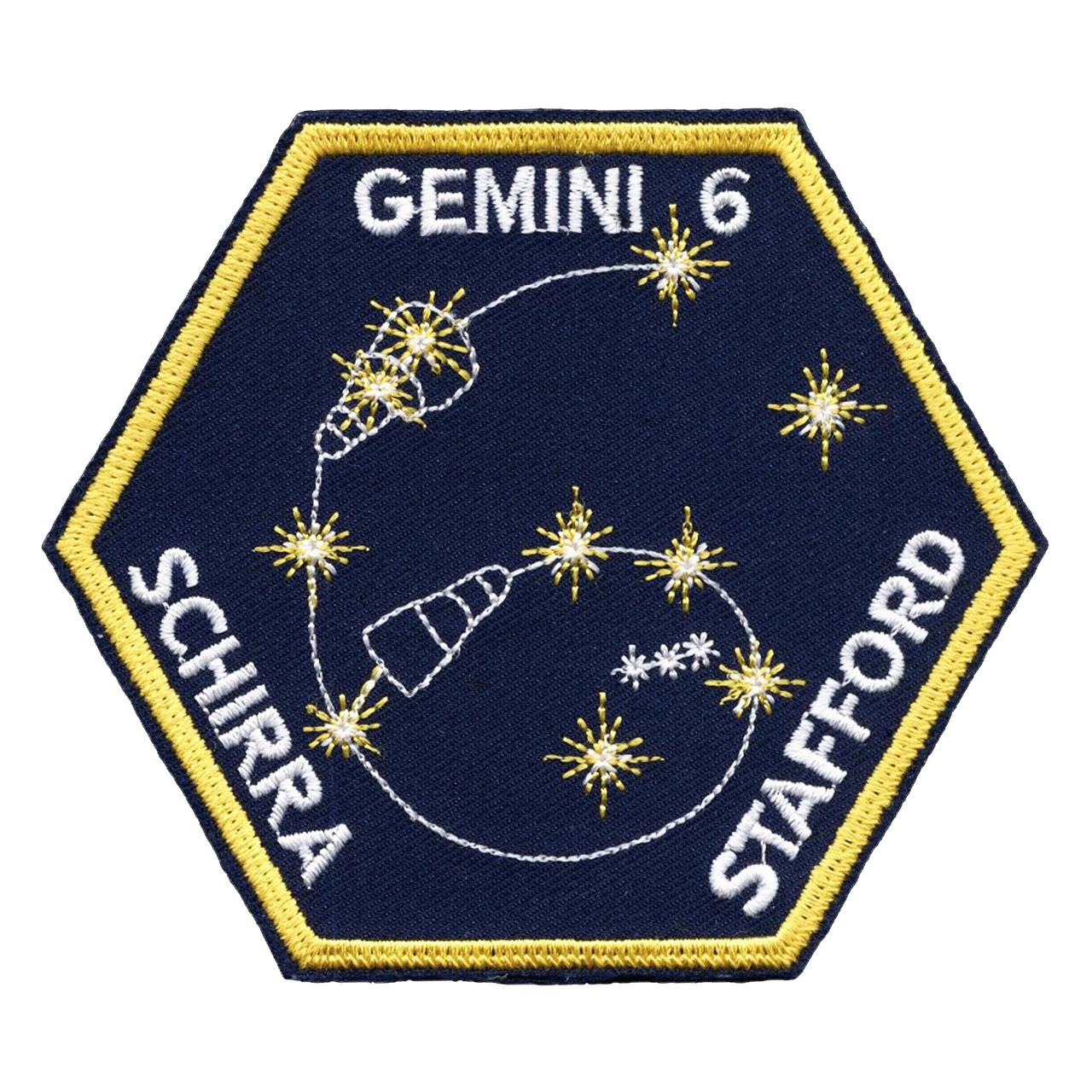
The Gemini 6 patch is hexagonal in shape, reflecting the mission number; and the spacecraft trajectory also traces out the number "6". The Gemini 6 spacecraft is shown superimposed on the "twin stars" Castor and Pollux, for "Gemini".
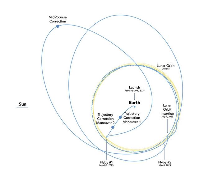
Lunar Trailblazer's voyage to the Moon will take between four and seven months, depending on the day it launches. This orbital diagram shows the low-energy transfer trajectory of the NASA mission should it launch on Feb. 26, the earliest date in a four-day launch period. If it launches that date, the spacecraft is expected to arrive in lunar orbit about four months later. Shown in this diagram are key dates of trajectory correction maneuvers, when the spacecraft will use its thrusters to shape its orbit, and lunar flybys. Lunar Trailblazer was a selection of NASA's SIMPLEx (Small Innovative Missions for Planetary Exploration), which provides opportunities for low-cost science spacecraft to ride-share with selected primary missions. To maintain the lower overall cost, SIMPLEx missions have a higher risk posture and lighter requirements for oversight and management. This higher risk acceptance allows NASA to test pioneering technologies, and the definition of success for these missions includes the lessons learned from more experimental endeavors. https://photojournal.jpl.nasa.gov/catalog/PIA26459
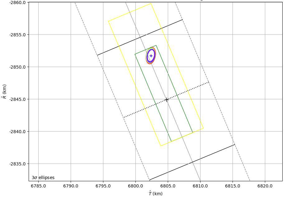
This graphic shows the B-Plane for NASA's Mars 2020 Perseverance rover mission as of February 15, 2021. A B-Plane is a key performance metric that navigators for interplanetary missions use to determine the accuracy of their spacecraft's trajectory. The entry target on the lower right of the image (black cross) depicts the point where mission navigators are targeting the Mars 2020 spacecraft to enter the Red Planet's atmosphere. Higher up, the red, orange, green, and blue ovals depict the estimated "entry uncertainty ellipse" for the spacecraft as determined by previous navigation solutions. The inner-most ring (purple) depicts the most recent trajectory path. https://photojournal.jpl.nasa.gov/catalog/PIA24296
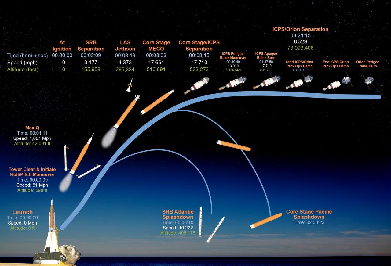
This graphic shows the time, speed, and altitude of key events from launch of the SLS (Space Launch System) rocket and Orion spacecraft and ascent to space, through Orion's perigee raise burn during the Artemis II test flight.

Over the past 30 years, global average sea level has risen a total of 3.6 inches (9.1 centimeters), as indicated in this graphic, which is based on sea level measurements (in blue) from five successive satellites starting with the U.S.-French TOPEX/Poseidon mission in 1993. The solid red line shows the trajectory of sea level rise from 1993 to 2022, while the dotted red line shows the increase sea level into the future. Researchers can take the solid red line and calculate the rate of sea level rise, which was 0.08 inches (0.20 centimeters) per year in 1993 and doubled to 0.17 inches (0.44 centimeters) per year by 2022. The dotted red line shows that by 2040, sea levels may rise by an additional 3.66 inches (9.3 cm) above 2022 levels. The trajectory shown in the solid and dotted red line is based on work by the NASA Sea Level Change Team and the Ocean Surface Topography Science Team. https://photojournal.jpl.nasa.gov/catalog/PIA25775

Portrait Katherine G. Johnson. Hall of Honor inductee 2017. Langley Research Center NACA and NASA Hall of Honor. In recognition of contributions to the development of methodologies for analysis of manned mission (from Mercury to Apollo) and satellite (Echo) trajectories, and dynamic control of large space structures.

iss042e016150 (11/26/2014) --- A view of the ELITE-S2 Trajectory Video Camera (TVC) aboard the International Space Station (ISS). The ELaboratore Immagini TElevisive - Space 2 (ELITE-S2) facility provides the experiment hardware to investigate the connection between brain, visualization and motion in the absence of gravity.
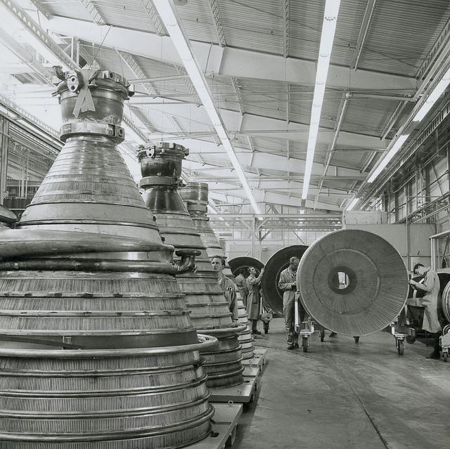
J-2 engines for the Saturn IB/Saturn V launch vehicles are lined up in the assembly area at Rocketdyne's manufacturing plant in Canoga Park, California. Five J-2 engines provided more than 1,000,000 pounds of thrust to accelerate the second stage toward a Moon trajectory.
The 41-G mission insignia focuses on its seven crew members (first to exceed six), the U.S. Flag and the Unity symbol known as the astronaut pin. The pin design in center shows a trio of trajectories merging in infinite space, capped by a bright shining star and encircled by an elliptical wreath denoting orbital flight.
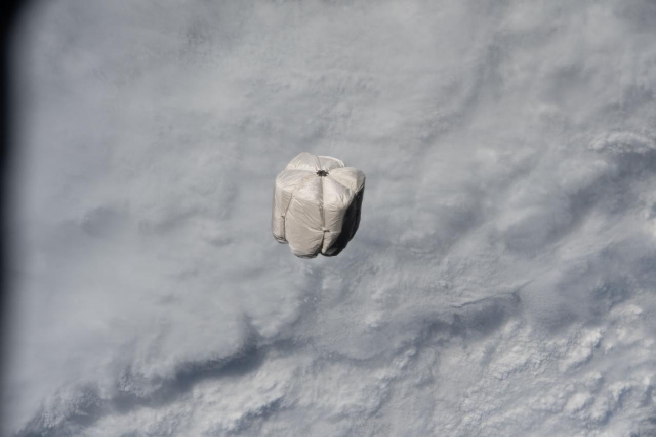
iss067e173472 (July 3, 2022) --- A trash container is pictured on a trajectory away from the International Space Station and toward the Earth's atmosphere for a fiery, but safe disposal. The trash container had been jettisoned moments earlier from the Nanoracks Bishop Airlock while attached to the Canadarm2 robotic arm.
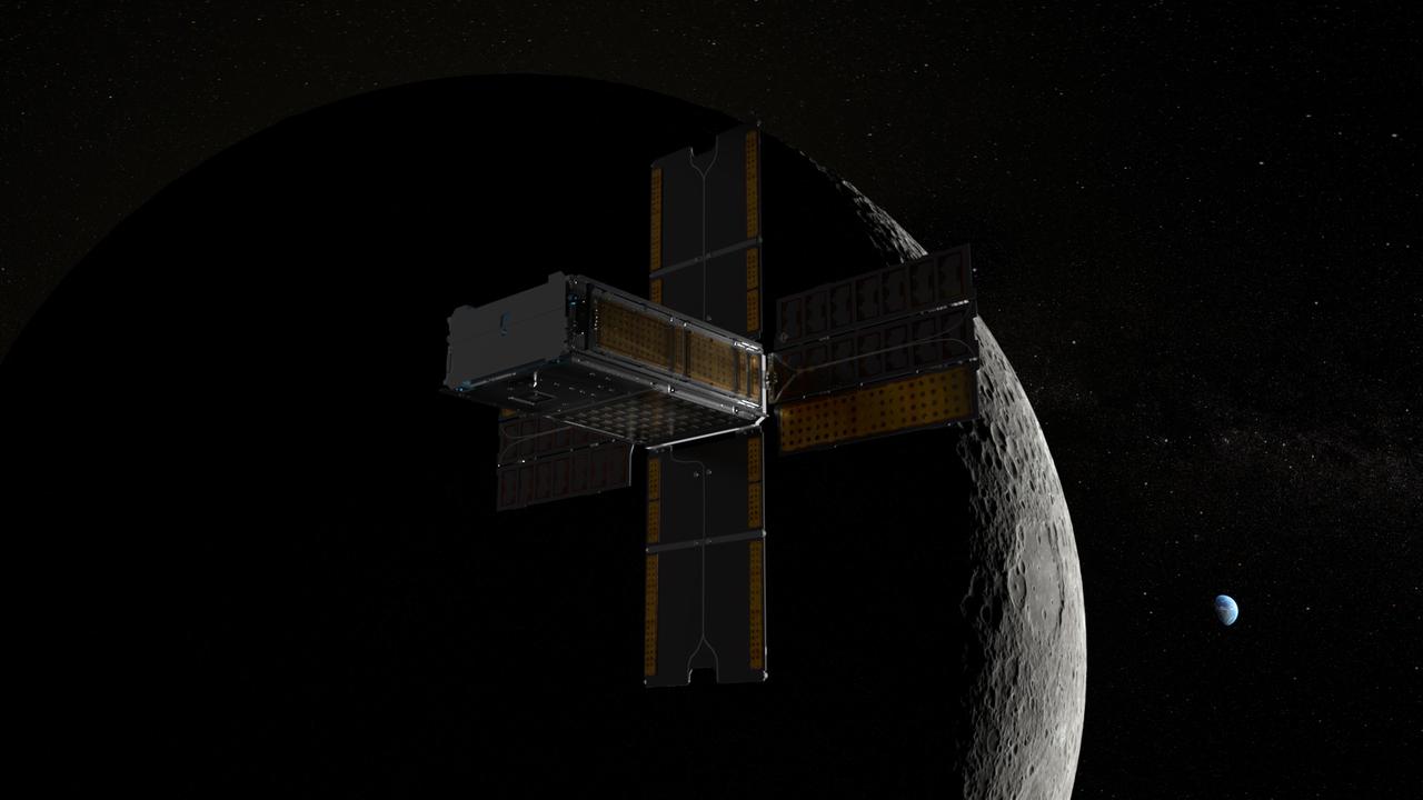
BioSentinel spacecraft leaves Earth and enters a lunar flyby trajectory into a heliocentric orbit. BioSentinel will detect and measure the impact of space radiation on living organisms over long durations beyond low-Earth orbit (LEO). Illustration by Daniel Rutter.
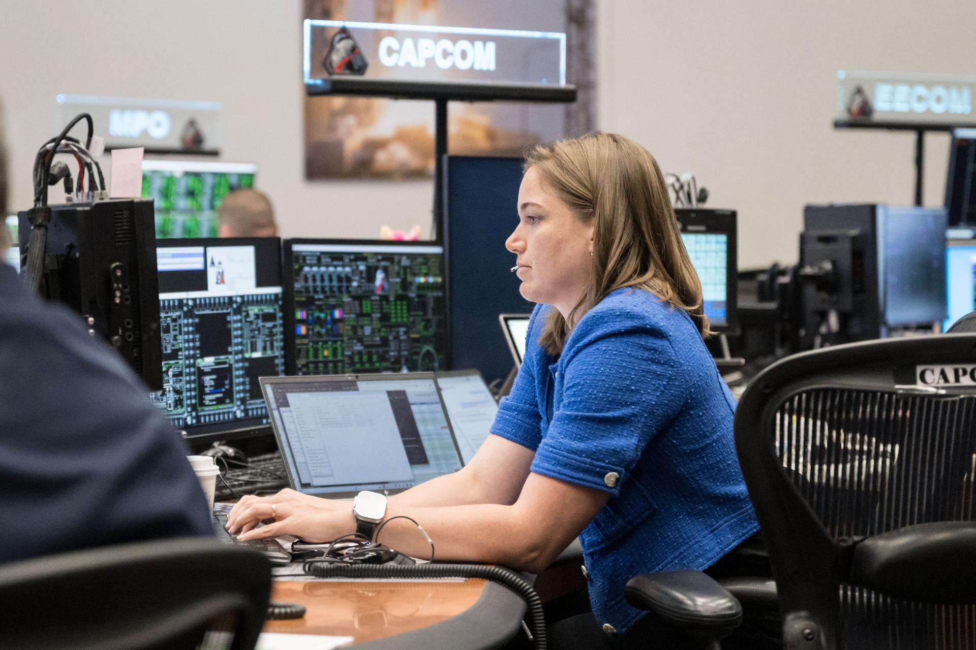
jsc2026e020046 (April 2, 2026) – CSA (Canadian Space Agency) astronaut and backup Artemis II crew member Jenni Gibbons serves as capsule communicator (capcom) during the mission’s translunar injection burn, which sent the crew in Orion out of Earth orbit and on a trajectory toward the Moon.
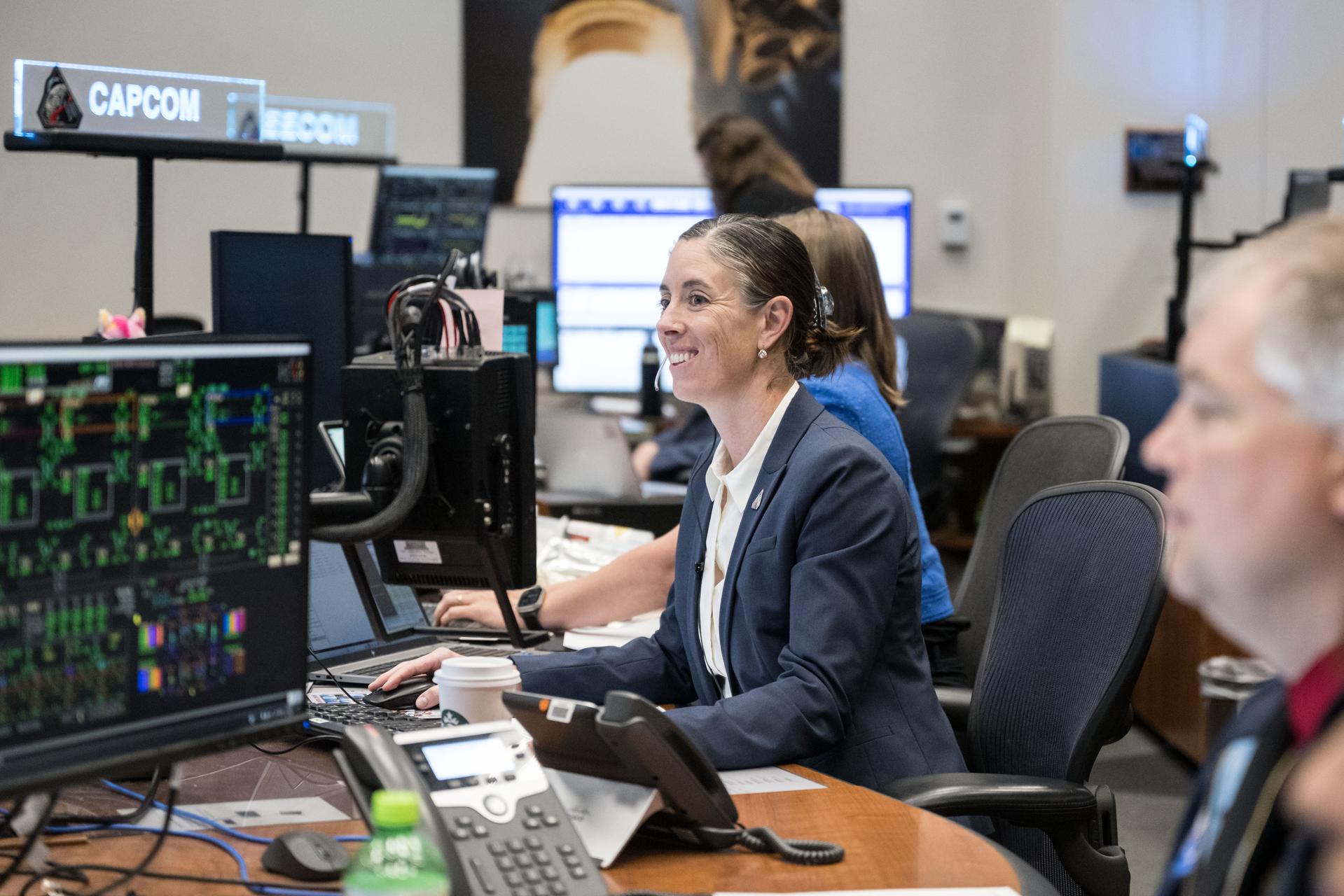
jsc2026e019614 (April 2, 2026) – NASA astronaut Chris Birch serves as capsule communicator (capcom) in the Mission Control Center at NASA’s Johnson Space Center during the mission’s translunar injection burn, which sent the crew in Orion out of Earth orbit and on a trajectory toward the Moon.
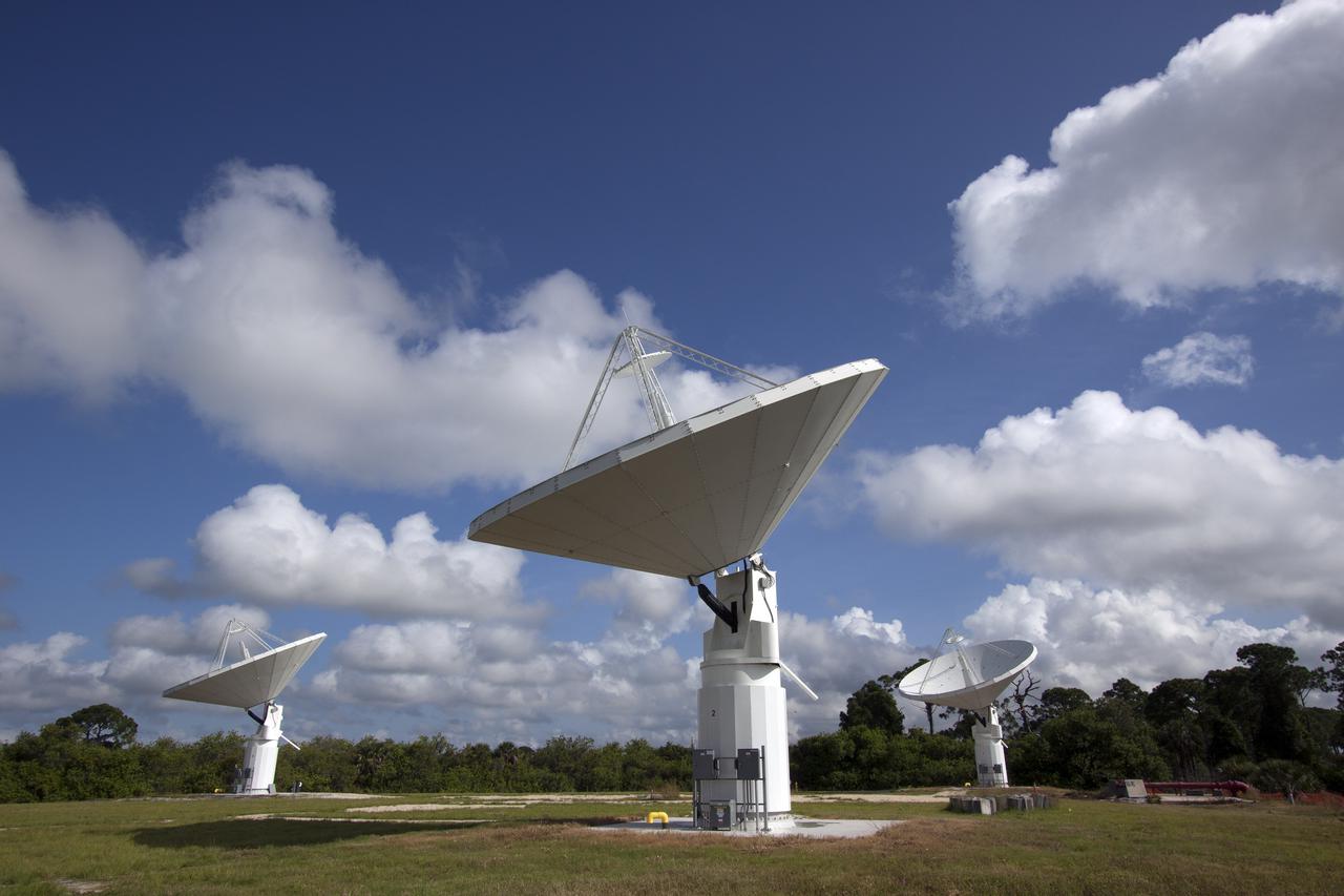
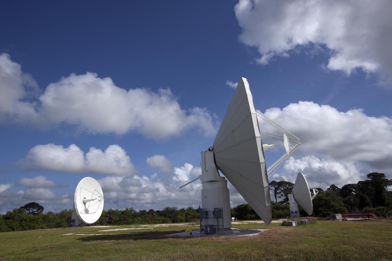
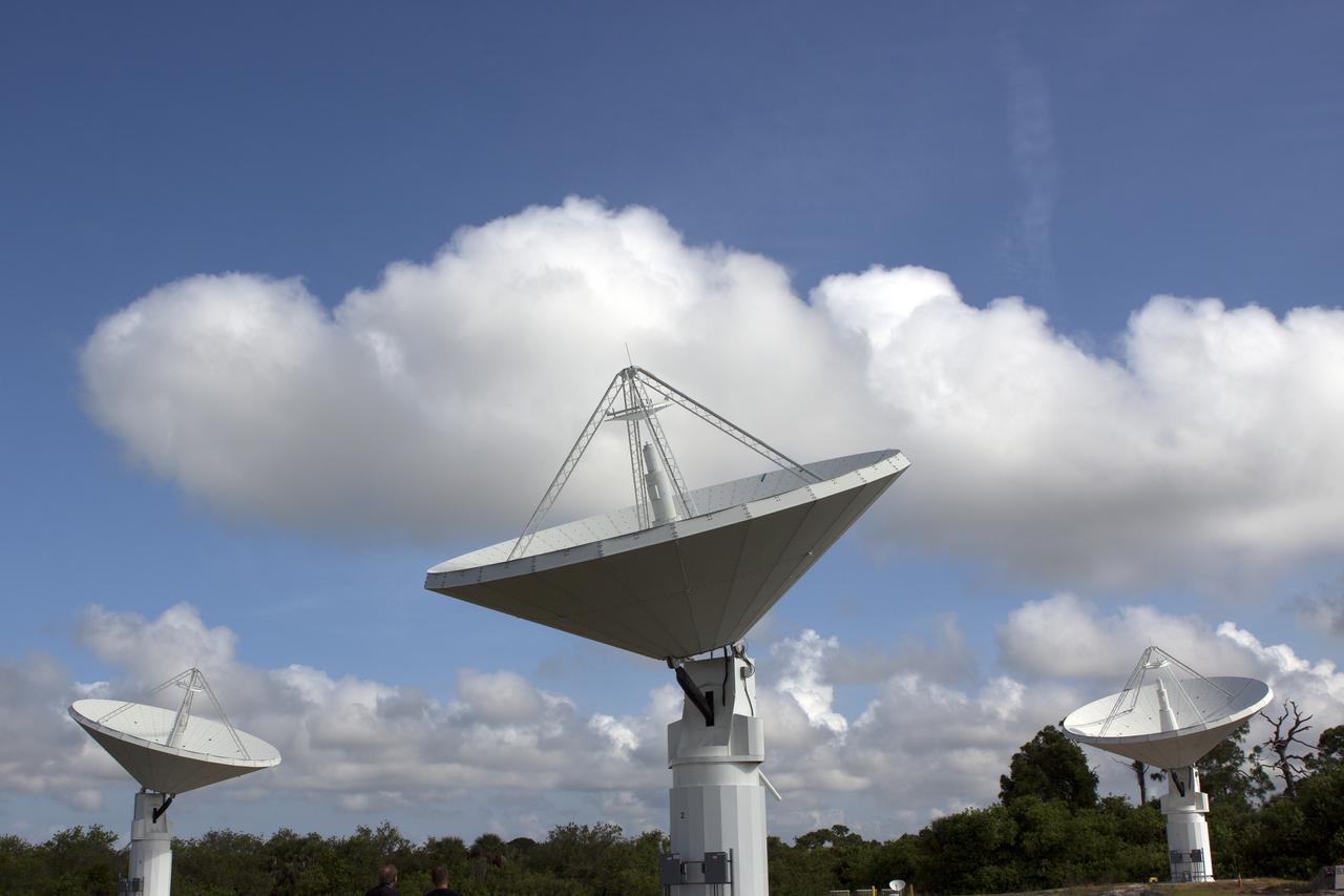
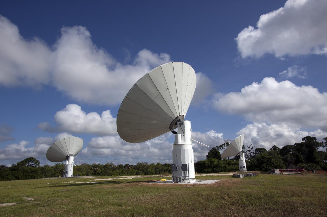
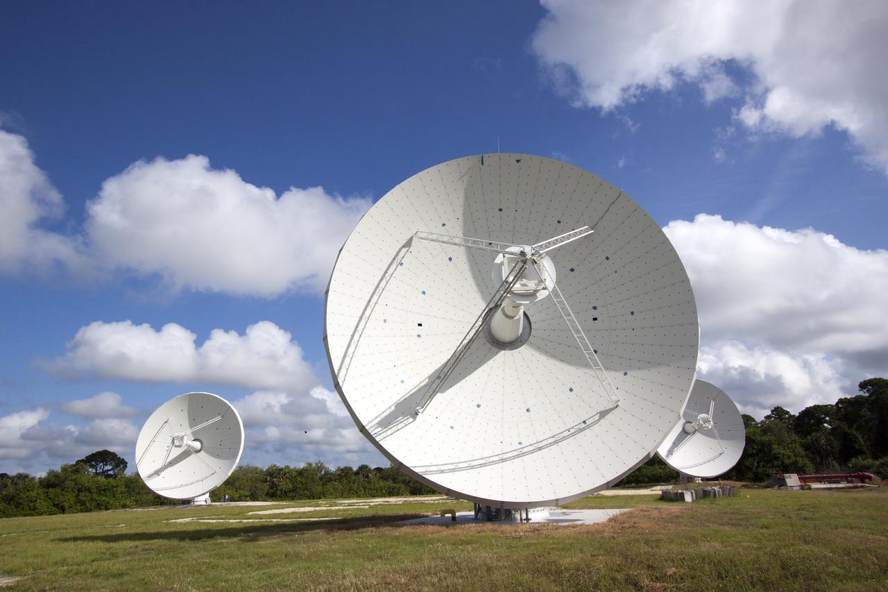
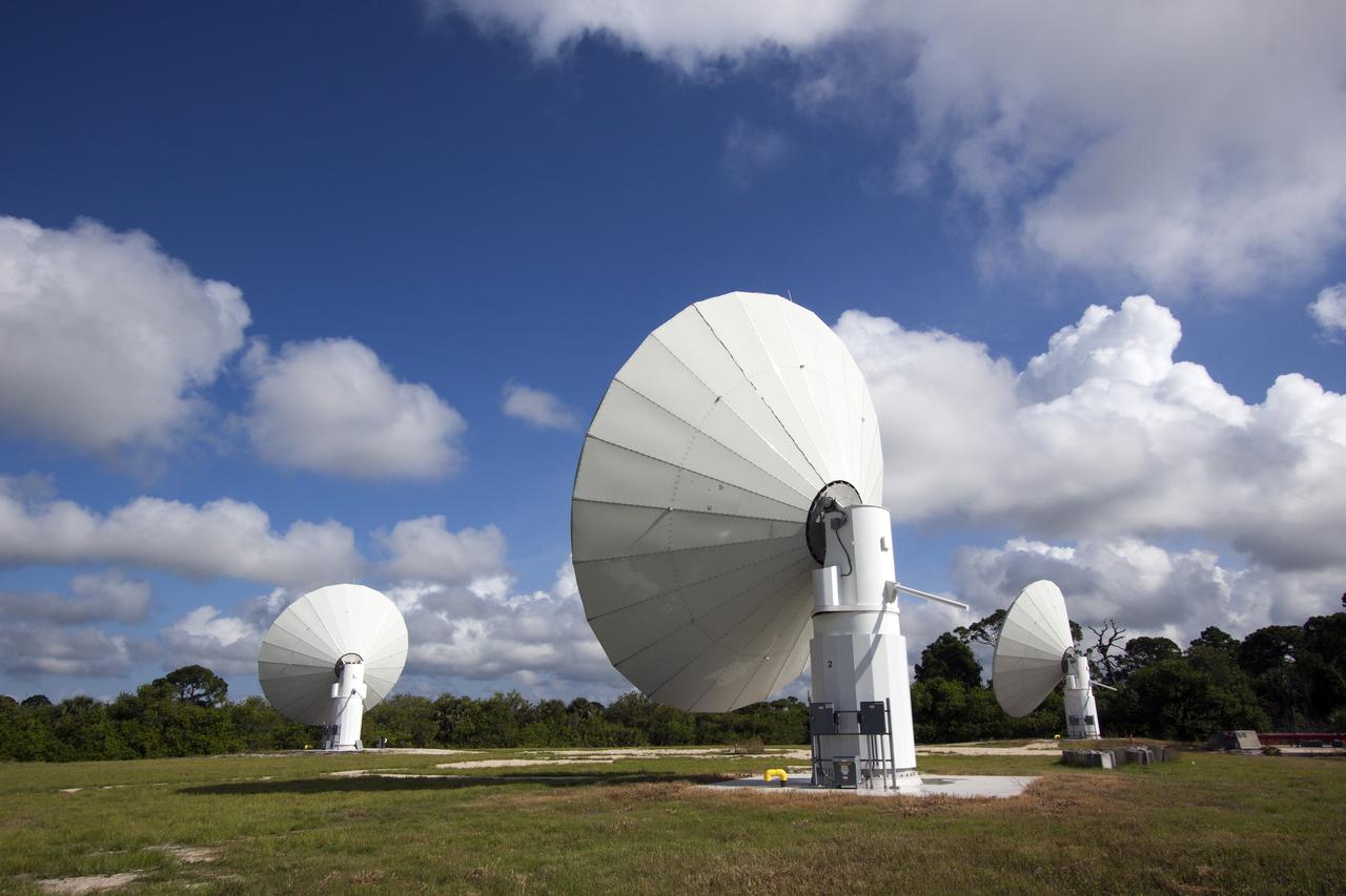
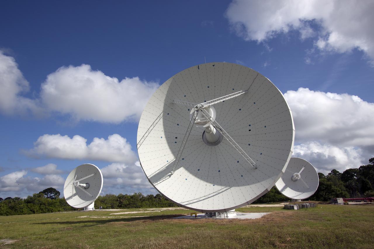
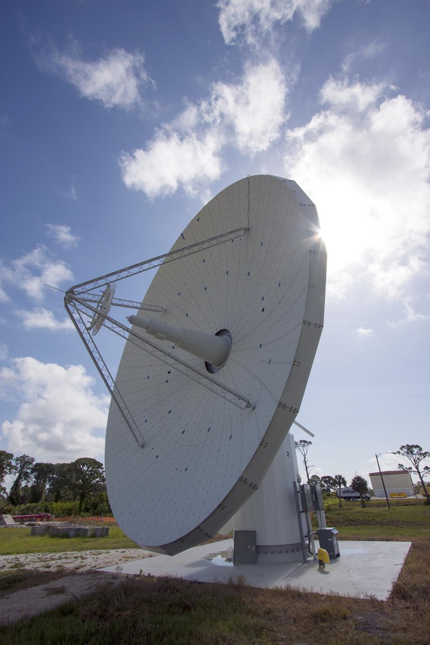
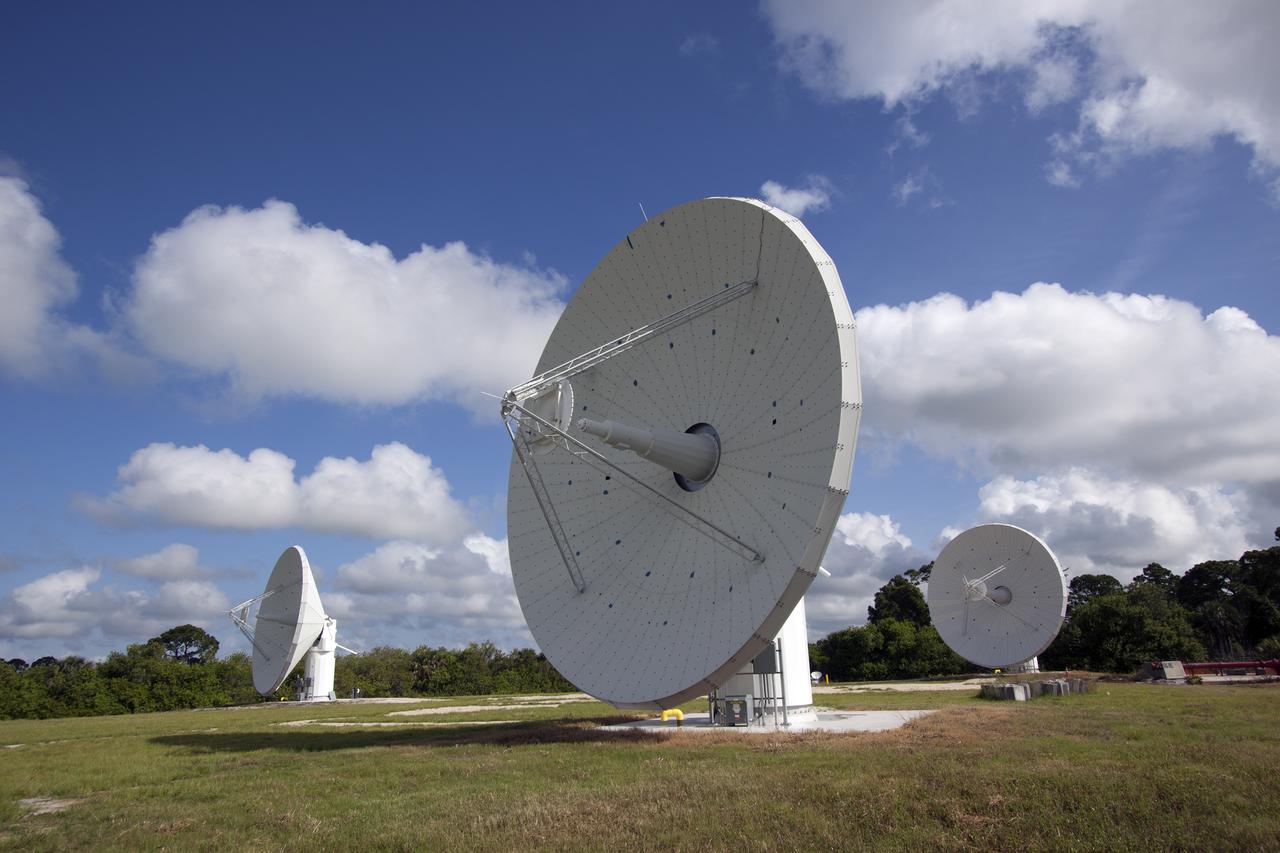
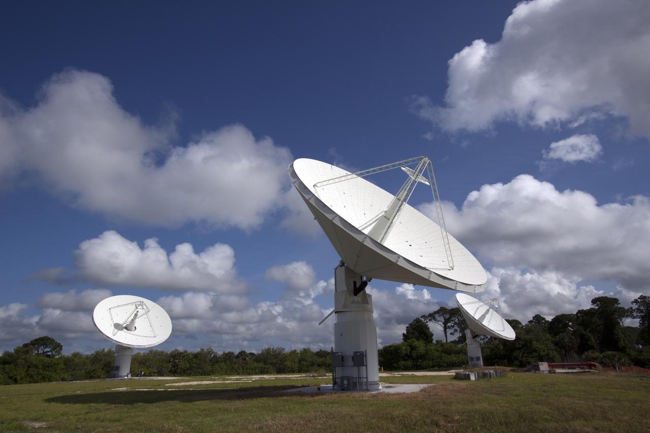
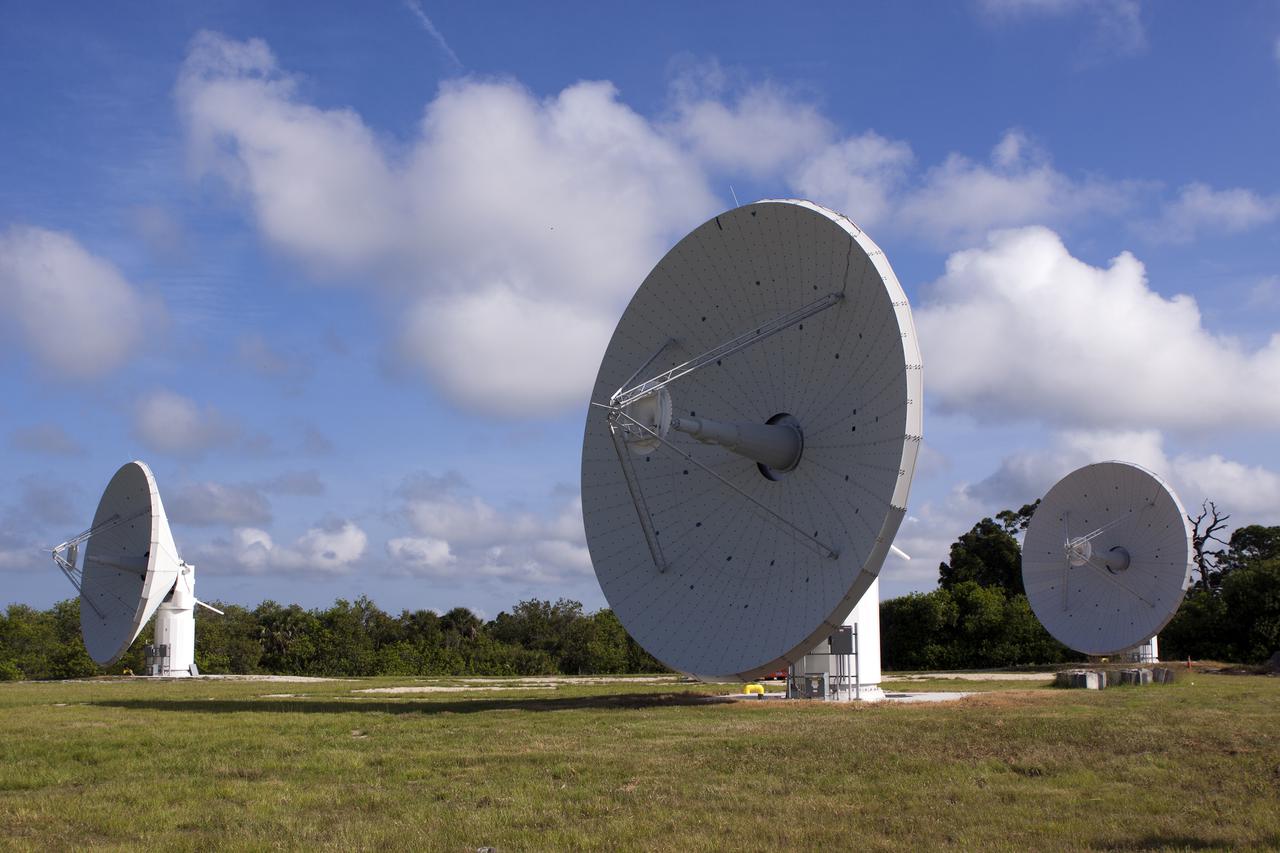
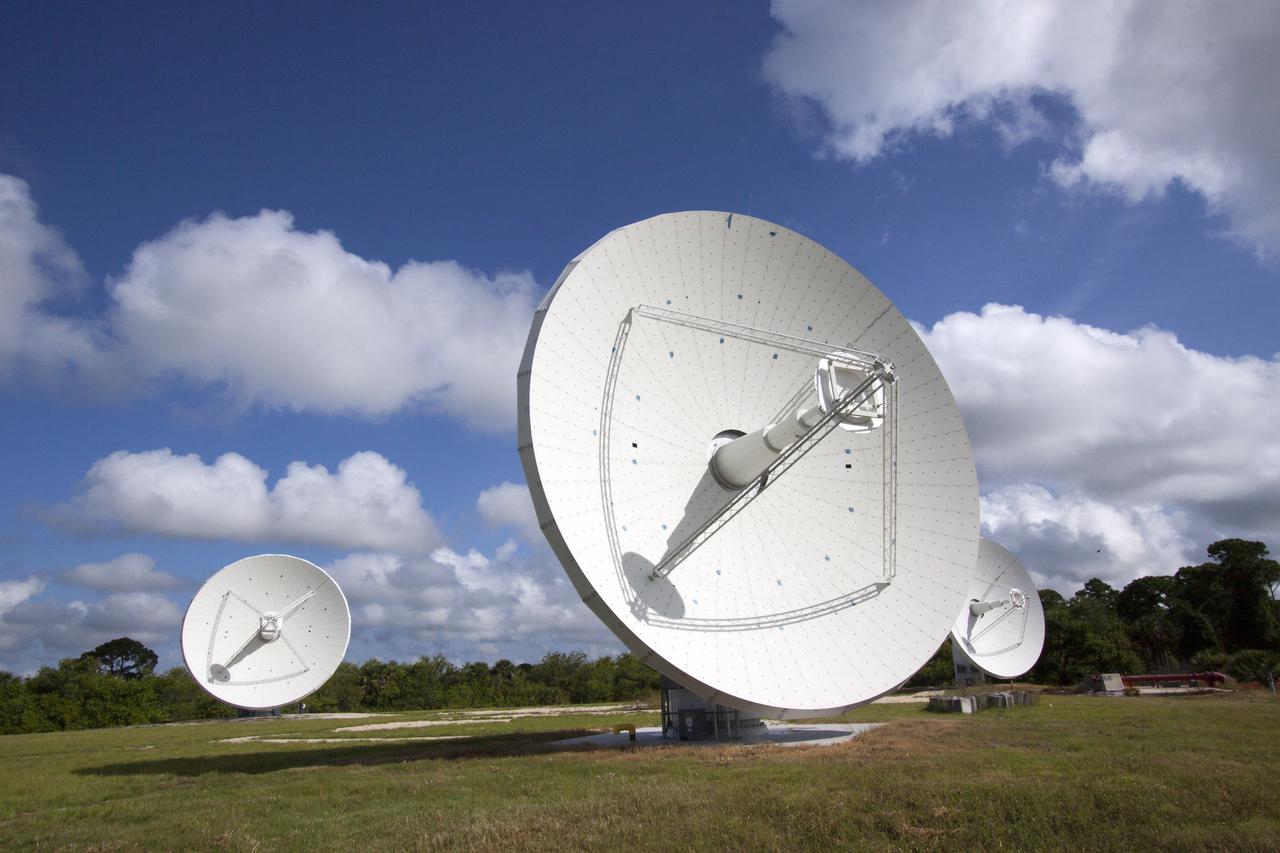
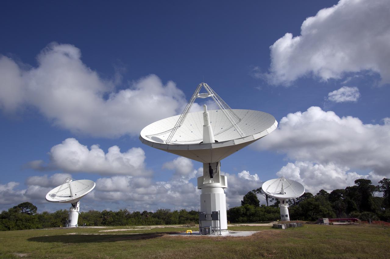
CAPE CANAVERAL, Fla. -- At NASA’s Kennedy Space Center in Florida, the three Ka-Band Objects Observation and Monitoring, or Ka-BOOM, testbed antennas are used to track the pattern of the sun during initial testing of the new system. The goal of Ka-BOOM is to prove technologies that will allow future systems to characterize near-Earth objects in terms of size, shape, rotation_tumble rate and to determine the trajectory of those objects. Radar studies can determine the trajectory 100,000 times more precisely than can optical methods. While also capable of space communication and radio science experiments, developing radar applications is the primary focus of the arrays. The 40-foot-diameter dish antenna arrays are at the site of the former Vertical Processing Facility, which has been demolished. Photo credit: NASA_Jim Grossmann
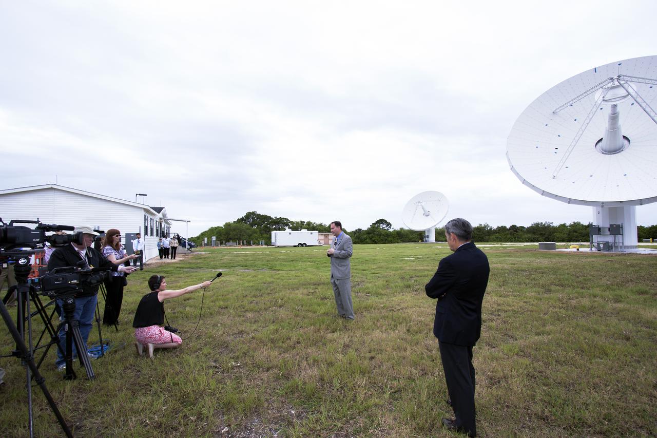
CAPE CANAVERAL, Fla. – At NASA’s Kennedy Space Center in Florida, Robert Lightfoot, NASA associate director, talks to members of the media at the Ka Band Objects Observation and Monitoring, or KaBOOM, testbed antenna array site during a tour of Kennedy facilities. At right, in the foreground is Kennedy Director Bob Cabana. The goal of KaBOOM is to prove technologies that will allow future systems to characterize near-Earth objects in terms of size, shape, rotation_tumble rate and to determine the trajectory of those objects. Radar studies can determine the trajectory 100,000 times more precisely than can optical methods. While also capable of space communication and radio science experiments, developing radar applications is the primary focus of the arrays. The 40-foot-diameter dish antenna arrays are at the site of the former Vertical Processing Facility, which has been demolished. Photo credit: NASA_Jim Grossmann
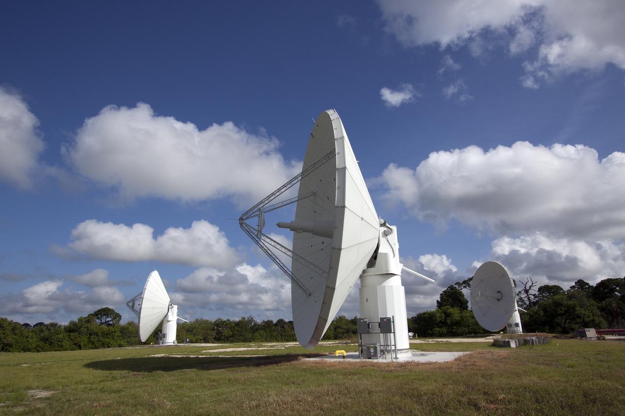
CAPE CANAVERAL, Fla. -- At NASA’s Kennedy Space Center in Florida, the three Ka-Band Objects Observation and Monitoring, or Ka-BOOM, testbed antennas are used to track the pattern of the sun during initial testing of the new system. The goal of Ka-BOOM is to prove technologies that will allow future systems to characterize near-Earth objects in terms of size, shape, rotation_tumble rate and to determine the trajectory of those objects. Radar studies can determine the trajectory 100,000 times more precisely than can optical methods. While also capable of space communication and radio science experiments, developing radar applications is the primary focus of the arrays. The 40-foot-diameter dish antenna arrays are at the site of the former Vertical Processing Facility, which has been demolished. Photo credit: NASA_Jim Grossmann
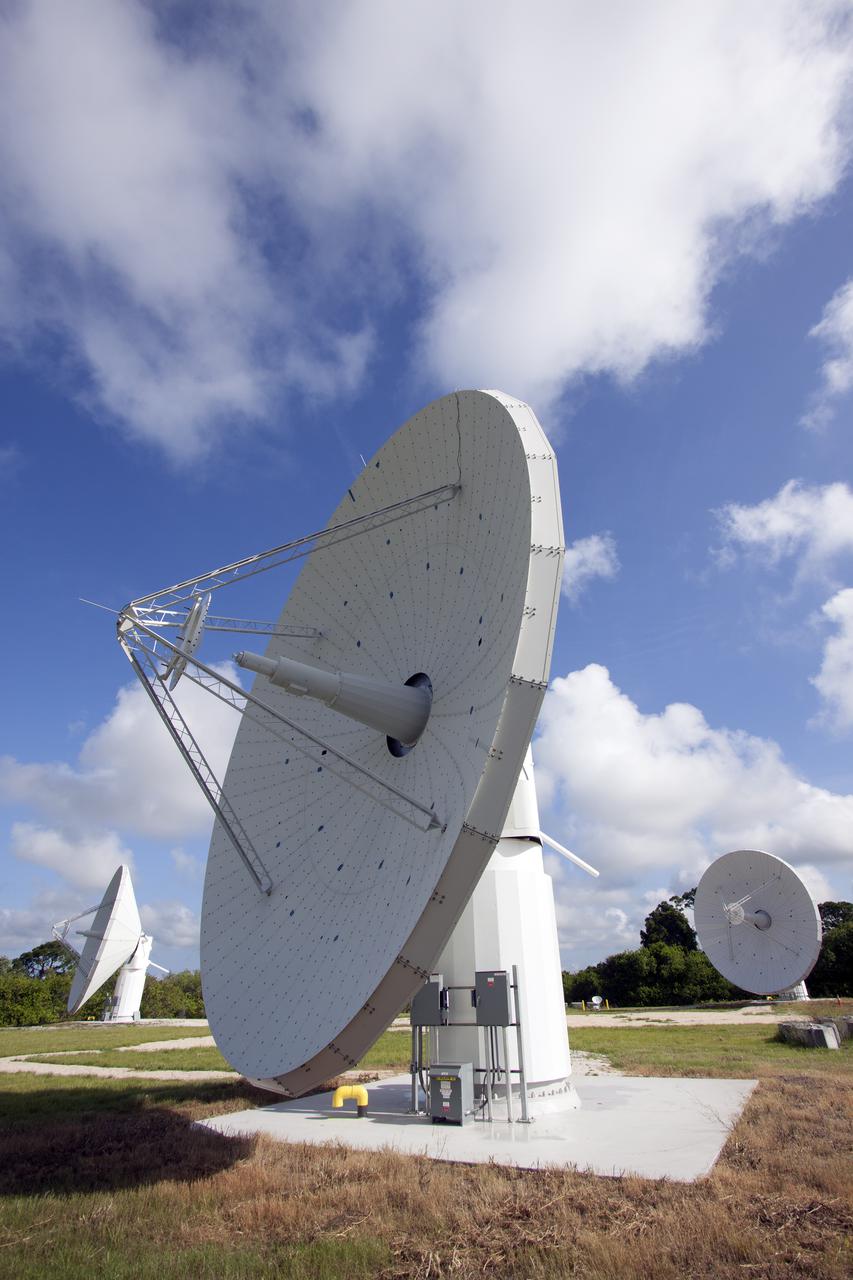
CAPE CANAVERAL, Fla. -- At NASA’s Kennedy Space Center in Florida, one of the three Ka-Band Objects Observation and Monitoring, or Ka-BOOM, testbed antennas is used to track the sun during initial testing of the new system. The goal of Ka-BOOM is to prove technologies that will allow future systems to characterize near-Earth objects in terms of size, shape, rotation_tumble rate and to determine the trajectory of those objects. Radar studies can determine the trajectory 100,000 times more precisely than can optical methods. While also capable of space communication and radio science experiments, developing radar applications is the primary focus of the arrays. The 40-foot-diameter dish antenna arrays are at the site of the former Vertical Processing Facility, which has been demolished. Photo credit: NASA_Jim Grossmann
CAPE CANAVERAL, Fla. -- At NASA’s Kennedy Space Center in Florida, the three Ka-Band Objects Observation and Monitoring, or Ka-BOOM, testbed antennas are used to track the pattern of the sun during initial testing of the new system. The goal of Ka-BOOM is to prove technologies that will allow future systems to characterize near-Earth objects in terms of size, shape, rotation_tumble rate and to determine the trajectory of those objects. Radar studies can determine the trajectory 100,000 times more precisely than can optical methods. While also capable of space communication and radio science experiments, developing radar applications is the primary focus of the arrays. The 40-foot-diameter dish antenna arrays are at the site of the former Vertical Processing Facility, which has been demolished. Photo credit: NASA_Jim Grossmann
CAPE CANAVERAL, Fla. -- At NASA’s Kennedy Space Center in Florida, the three Ka-Band Objects Observation and Monitoring, or Ka-BOOM, testbed antennas are used to track the pattern of the sun during initial testing of the new system. The goal of Ka-BOOM is to prove technologies that will allow future systems to characterize near-Earth objects in terms of size, shape, rotation_tumble rate and to determine the trajectory of those objects. Radar studies can determine the trajectory 100,000 times more precisely than can optical methods. While also capable of space communication and radio science experiments, developing radar applications is the primary focus of the arrays. The 40-foot-diameter dish antenna arrays are at the site of the former Vertical Processing Facility, which has been demolished. Photo credit: NASA_Jim Grossmann
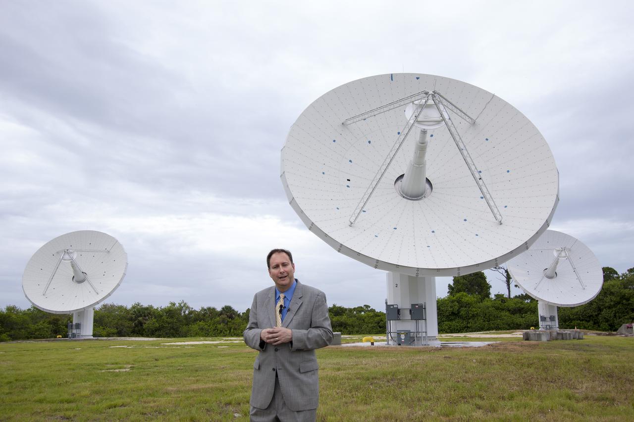
CAPE CANAVERAL, Fla. – At NASA’s Kennedy Space Center in Florida, Robert Lightfoot, NASA associate director, talks to members of the media at the Ka Band Objects Observation and Monitoring, or KaBOOM, testbed antenna array site during a tour of Kennedy facilities. The goal of KaBOOM is to prove technologies that will allow future systems to characterize near-Earth objects in terms of size, shape, rotation_tumble rate and to determine the trajectory of those objects. Radar studies can determine the trajectory 100,000 times more precisely than can optical methods. While also capable of space communication and radio science experiments, developing radar applications is the primary focus of the arrays. The 40-foot-diameter dish antenna arrays are at the site of the former Vertical Processing Facility, which has been demolished. Photo credit: NASA_Jim Grossmann
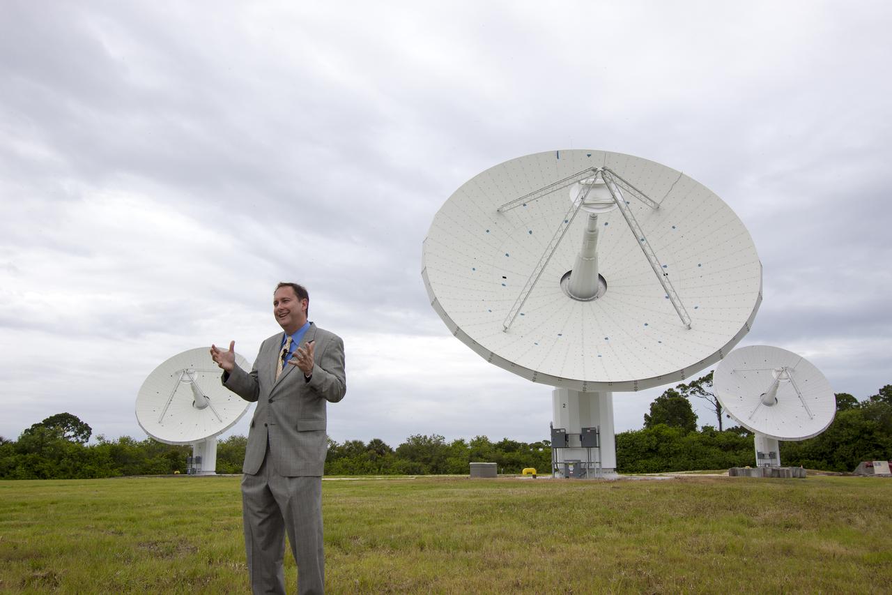
CAPE CANAVERAL, Fla. – At NASA’s Kennedy Space Center in Florida, Robert Lightfoot, NASA associate director, talks to members of the media at the Ka Band Objects Observation and Monitoring, or KaBOOM, testbed antenna array site during a tour of Kennedy facilities. The goal of KaBOOM is to prove technologies that will allow future systems to characterize near-Earth objects in terms of size, shape, rotation_tumble rate and to determine the trajectory of those objects. Radar studies can determine the trajectory 100,000 times more precisely than can optical methods. While also capable of space communication and radio science experiments, developing radar applications is the primary focus of the arrays. The 40-foot-diameter dish antenna arrays are at the site of the former Vertical Processing Facility, which has been demolished. Photo credit: NASA_Jim Grossmann
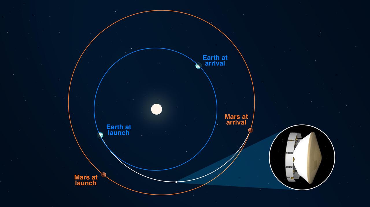
NASA's Mars 2020 Perseverance rover reached its halfway point to Jezero Crater on Oct. 27, 2020 at 1:40 p.m. PDT (4:40 EDT), having completed as many miles — 146.3 million miles (235.4 million kilometers) — as it has yet to travel on its journey to Mars. In straight-line distance, Earth is 26.6 million miles (42.7 million kilometers) behind Perseverance, and Mars is 17.9 million miles (28.8 million kilometers) in front. This illustration depicts the curved trajectory of the spacecraft (seen in inset: cruise stage, descent stage, back shell, and heat shield, plus the rover and Mars Helicopter), noting the positions of Earth and Mars relative to each other both at the time of launch and the time of landing. The trajectory's curvature is a result of the Sun's gravitational influence on the spacecraft. https://photojournal.jpl.nasa.gov/catalog/PIA24232
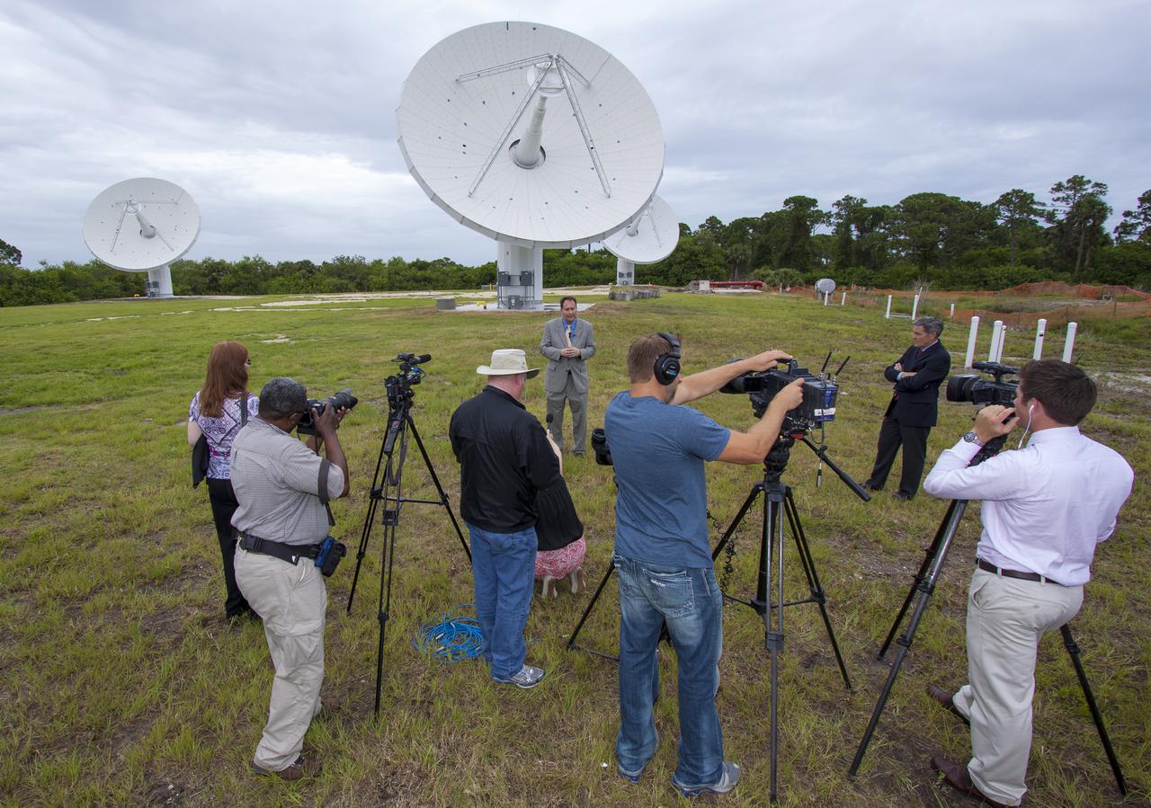
CAPE CANAVERAL, Fla. – At NASA’s Kennedy Space Center in Florida, Robert Lightfoot, NASA associate director, talks to members of the media at the Ka Band Objects Observation and Monitoring, or KaBOOM, testbed antenna array site during a tour of Kennedy facilities. At right is Kennedy Director Bob Cabana. The goal of KaBOOM is to prove technologies that will allow future systems to characterize near-Earth objects in terms of size, shape, rotation_tumble rate and to determine the trajectory of those objects. Radar studies can determine the trajectory 100,000 times more precisely than can optical methods. While also capable of space communication and radio science experiments, developing radar applications is the primary focus of the arrays. The 40-foot-diameter dish antenna arrays are at the site of the former Vertical Processing Facility, which has been demolished. Photo credit: NASA_Jim Grossmann
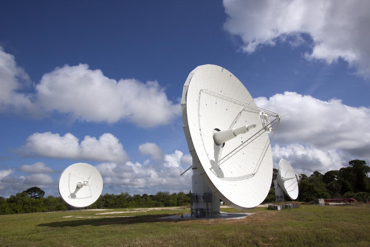
CAPE CANAVERAL, Fla. -- At NASA’s Kennedy Space Center in Florida, the three Ka-Band Objects Observation and Monitoring, or Ka-BOOM, testbed antennas are used to track the pattern of the sun during initial testing of the new system. The goal of Ka-BOOM is to prove technologies that will allow future systems to characterize near-Earth objects in terms of size, shape, rotation_tumble rate and to determine the trajectory of those objects. Radar studies can determine the trajectory 100,000 times more precisely than can optical methods. While also capable of space communication and radio science experiments, developing radar applications is the primary focus of the arrays. The 40-foot-diameter dish antenna arrays are at the site of the former Vertical Processing Facility, which has been demolished. Photo credit: NASA_Jim Grossmann
CAPE CANAVERAL, Fla. -- At NASA’s Kennedy Space Center in Florida, the three Ka-Band Objects Observation and Monitoring, or Ka-BOOM, testbed antennas are used to track the pattern of the sun during initial testing of the new system. The goal of Ka-BOOM is to prove technologies that will allow future systems to characterize near-Earth objects in terms of size, shape, rotation_tumble rate and to determine the trajectory of those objects. Radar studies can determine the trajectory 100,000 times more precisely than can optical methods. While also capable of space communication and radio science experiments, developing radar applications is the primary focus of the arrays. The 40-foot-diameter dish antenna arrays are at the site of the former Vertical Processing Facility, which has been demolished. Photo credit: NASA_Jim Grossmann
CAPE CANAVERAL, Fla. -- At NASA’s Kennedy Space Center in Florida, the three Ka-Band Objects Observation and Monitoring, or Ka-BOOM, testbed antennas are used to track the pattern of the sun during initial testing of the new system. The goal of Ka-BOOM is to prove technologies that will allow future systems to characterize near-Earth objects in terms of size, shape, rotation_tumble rate and to determine the trajectory of those objects. Radar studies can determine the trajectory 100,000 times more precisely than can optical methods. While also capable of space communication and radio science experiments, developing radar applications is the primary focus of the arrays. The 40-foot-diameter dish antenna arrays are at the site of the former Vertical Processing Facility, which has been demolished. Photo credit: NASA_Jim Grossmann
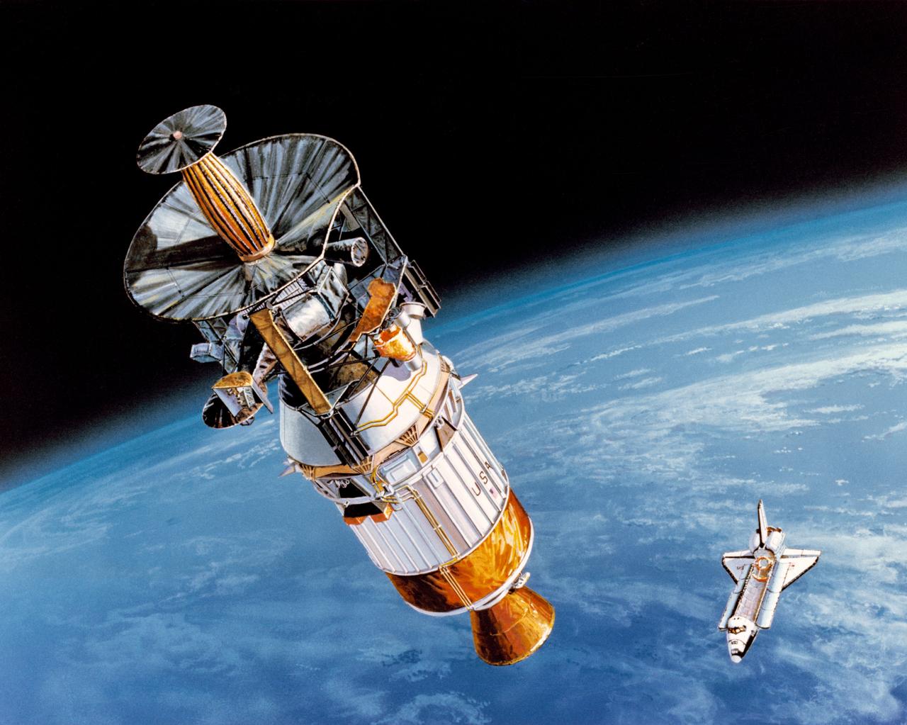
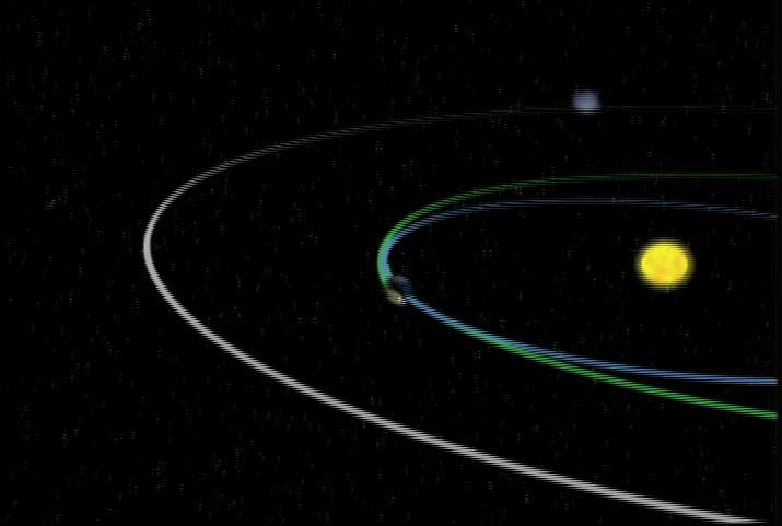
S89-42940 (April 1989) --- In this artist's rendition, the Galileo spacecraft is being boosted into its inter-planetary trajectory by the Inertial Upper Stage (IUS) rocket. The Space Shuttle Atlantis, which is scheduled to take Galileo and the IUS from Earth's surface into space, is depicted against the curve of Earth. Galileo will be placed on a trajectory to Venus, from which it will return to Earth at higher velocity and then gain still more energy in two gravity-assist passes, until it has enough velocity to reach Jupiter. Passing Venus, it will take scientific data using instruments designed for observing Jupiter; later, it will make measurements at Earth and the moon, crossing above the moon's north pole in the second pass. Between the two Earth passes, it will edge into the asteroid belt, beyond Mars' orbit; there, the first close-up observation of an asteroid is planned. Crossing the belt later, another asteroid flyby is possible.
CAPE CANAVERAL, Fla. -- At NASA’s Kennedy Space Center in Florida, the three Ka-Band Objects Observation and Monitoring, or Ka-BOOM, testbed antennas are used to track the pattern of the sun during initial testing of the new system. The goal of Ka-BOOM is to prove technologies that will allow future systems to characterize near-Earth objects in terms of size, shape, rotation_tumble rate and to determine the trajectory of those objects. Radar studies can determine the trajectory 100,000 times more precisely than can optical methods. While also capable of space communication and radio science experiments, developing radar applications is the primary focus of the arrays. The 40-foot-diameter dish antenna arrays are at the site of the former Vertical Processing Facility, which has been demolished. Photo credit: NASA_Jim Grossmann
CAPE CANAVERAL, Fla. -- At NASA’s Kennedy Space Center in Florida, one of the three Ka-Band Objects Observation and Monitoring, or Ka-BOOM, testbed antennas is used to track the pattern of the sun during initial testing of the new system. The goal of Ka-BOOM is to prove technologies that will allow future systems to characterize near-Earth objects in terms of size, shape, rotation_tumble rate and to determine the trajectory of those objects. Radar studies can determine the trajectory 100,000 times more precisely than can optical methods. While also capable of space communication and radio science experiments, developing radar applications is the primary focus of the arrays. The 40-foot-diameter dish antenna arrays are at the site of the former Vertical Processing Facility, which has been demolished. Photo credit: NASA_Jim Grossmann
CAPE CANAVERAL, Fla. -- At NASA’s Kennedy Space Center in Florida, one of the three Ka-Band Objects Observation and Monitoring, or Ka-BOOM, testbed antennas is used to track the pattern of the sun during initial testing of the new system. The goal of Ka-BOOM is to prove technologies that will allow future systems to characterize near-Earth objects in terms of size, shape, rotation_tumble rate and to determine the trajectory of those objects. Radar studies can determine the trajectory 100,000 times more precisely than can optical methods. While also capable of space communication and radio science experiments, developing radar applications is the primary focus of the arrays. The 40-foot-diameter dish antenna arrays are at the site of the former Vertical Processing Facility, which has been demolished. Photo credit: NASA_Jim Grossmann
CAPE CANAVERAL, Fla. -- At NASA’s Kennedy Space Center in Florida, the three Ka-Band Objects Observation and Monitoring, or Ka-BOOM, testbed antennas are used to track the pattern of the sun during initial testing of the new system. The goal of Ka-BOOM is to prove technologies that will allow future systems to characterize near-Earth objects in terms of size, shape, rotation_tumble rate and to determine the trajectory of those objects. Radar studies can determine the trajectory 100,000 times more precisely than can optical methods. While also capable of space communication and radio science experiments, developing radar applications is the primary focus of the arrays. The 40-foot-diameter dish antenna arrays are at the site of the former Vertical Processing Facility, which has been demolished. Photo credit: NASA_Jim Grossmann
CAPE CANAVERAL, Fla. -- At NASA’s Kennedy Space Center in Florida, one of the three Ka-Band Objects Observation and Monitoring, or Ka-BOOM, testbed antennas is used to track the sun during initial testing of the new system. The goal of Ka-BOOM is to prove technologies that will allow future systems to characterize near-Earth objects in terms of size, shape, rotation_tumble rate and to determine the trajectory of those objects. Radar studies can determine the trajectory 100,000 times more precisely than can optical methods. While also capable of space communication and radio science experiments, developing radar applications is the primary focus of the arrays. The 40-foot-diameter dish antenna arrays are at the site of the former Vertical Processing Facility, which has been demolished. Photo credit: NASA_Jim Grossmann
CAPE CANAVERAL, Fla. -- At NASA’s Kennedy Space Center in Florida, the three Ka-Band Objects Observation and Monitoring, or Ka-BOOM, testbed antennas are used to track the pattern of the sun during initial testing of the new system. The goal of Ka-BOOM is to prove technologies that will allow future systems to characterize near-Earth objects in terms of size, shape, rotation_tumble rate and to determine the trajectory of those objects. Radar studies can determine the trajectory 100,000 times more precisely than can optical methods. While also capable of space communication and radio science experiments, developing radar applications is the primary focus of the arrays. The 40-foot-diameter dish antenna arrays are at the site of the former Vertical Processing Facility, which has been demolished. Photo credit: NASA_Jim Grossmann
CAPE CANAVERAL, Fla. -- At NASA’s Kennedy Space Center in Florida, the three Ka-Band Objects Observation and Monitoring, or Ka-BOOM, testbed antennas are used to track the pattern of the sun during initial testing of the new system. The goal of Ka-BOOM is to prove technologies that will allow future systems to characterize near-Earth objects in terms of size, shape, rotation_tumble rate and to determine the trajectory of those objects. Radar studies can determine the trajectory 100,000 times more precisely than can optical methods. While also capable of space communication and radio science experiments, developing radar applications is the primary focus of the arrays. The 40-foot-diameter dish antenna arrays are at the site of the former Vertical Processing Facility, which has been demolished. Photo credit: NASA_Jim Grossmann
CAPE CANAVERAL, Fla. -- At NASA’s Kennedy Space Center in Florida, the three Ka-Band Objects Observation and Monitoring, or Ka-BOOM, testbed antennas are used to track the pattern of the sun during initial testing of the new system. The goal of Ka-BOOM is to prove technologies that will allow future systems to characterize near-Earth objects in terms of size, shape, rotation_tumble rate and to determine the trajectory of those objects. Radar studies can determine the trajectory 100,000 times more precisely than can optical methods. While also capable of space communication and radio science experiments, developing radar applications is the primary focus of the arrays. The 40-foot-diameter dish antenna arrays are at the site of the former Vertical Processing Facility, which has been demolished. Photo credit: NASA_Jim Grossmann
Using data collected by NASA's OSIRIS-REx mission, this animation shows the trajectories of rocky particles after being ejected from asteroid (101955) Bennu's surface. The animation emphasizes the four largest particle-ejection events detected at Bennu between December 2018 and September 2019. Additional particles not related to the ejections are also visible. Most of these pebble-size pieces of rock, typically measuring around a quarter inch (7 millimeters), were pulled back to Bennu under the asteroid's weak gravity after a short hop, sometimes even ricocheting back into space after colliding with the surface. Others remained in orbit for a few days and up to 16 revolutions. And some were ejected with enough force to completely escape from the Bennu environs. OSIRIS-REx — which stands for Origins, Spectral Interpretation, Resource Identification, and Security-Regolith Explorer — arrived at Bennu in December 2018. On Oct. 20, 2020, the mission will attempt to briefly touch down on the asteroid to scoop up material likely to include particles that were ejected before dropping back to the surface. If all goes as planned, the spacecraft will return to Earth in September 2023 with a cache of Bennu's particles for further study, including of which may even hold the physical clues as to what ejection mechanisms are at play. Movie available at https://photojournal.jpl.nasa.gov/catalog/PIA24101
![CAPE CANAVERAL, Fla. – In the Astrotech payload processing facility in Titusville, Fla. , the STSS Demonstrator SV-1 spacecraft is lowered onto a stand. The spacecraft is a midcourse tracking technology demonstrator, part of an evolving ballistic missile defense system. STSS is capable of tracking objects after boost phase and provides trajectory information to other sensors. It will be launched by NASA for the Missile Defense Agency in late summer. Photo credit: NASA/Tim Jacobs (Approved for Public Release 09-MDA-4800 [30 July 09] )](https://images-assets.nasa.gov/image/KSC-2009-4623/KSC-2009-4623~medium.jpg)
CAPE CANAVERAL, Fla. – In the Astrotech payload processing facility in Titusville, Fla. , the STSS Demonstrator SV-1 spacecraft is lowered onto a stand. The spacecraft is a midcourse tracking technology demonstrator, part of an evolving ballistic missile defense system. STSS is capable of tracking objects after boost phase and provides trajectory information to other sensors. It will be launched by NASA for the Missile Defense Agency in late summer. Photo credit: NASA/Tim Jacobs (Approved for Public Release 09-MDA-4800 [30 July 09] )
![CAPE CANAVERAL, Fla. – The STSS Demonstrator SV-2spacecraft arrives at the Astrotech payload processing facility in Titusville, Fla. The spacecraft is a midcourse tracking technology demonstrator, part of an evolving ballistic missile defense system. STSS is capable of tracking objects after boost phase and provides trajectory information to other sensors. It will be launched by NASA for the Missile Defense Agency in late summer. Photo credit: NASA/Jack Pfaller (Approved for Public Release 09-MDA-4616 [27 May 09])](https://images-assets.nasa.gov/image/KSC-2009-3667/KSC-2009-3667~medium.jpg)
CAPE CANAVERAL, Fla. – The STSS Demonstrator SV-2spacecraft arrives at the Astrotech payload processing facility in Titusville, Fla. The spacecraft is a midcourse tracking technology demonstrator, part of an evolving ballistic missile defense system. STSS is capable of tracking objects after boost phase and provides trajectory information to other sensors. It will be launched by NASA for the Missile Defense Agency in late summer. Photo credit: NASA/Jack Pfaller (Approved for Public Release 09-MDA-4616 [27 May 09])
![CAPE CANAVERAL, Fla. – A flatbed truck carrying the STSS Demonstrator SV-2spacecraft arrives at the Astrotech payload processing facility in Titusville, Fla. The spacecraft is a midcourse tracking technology demonstrator, part of an evolving ballistic missile defense system. STSS is capable of tracking objects after boost phase and provides trajectory information to other sensors. It will be launched by NASA for the Missile Defense Agency in late summer. Photo credit: NASA/Jack Pfaller (Approved for Public Release 09-MDA-4616 [27 May 09])](https://images-assets.nasa.gov/image/KSC-2009-3666/KSC-2009-3666~medium.jpg)
CAPE CANAVERAL, Fla. – A flatbed truck carrying the STSS Demonstrator SV-2spacecraft arrives at the Astrotech payload processing facility in Titusville, Fla. The spacecraft is a midcourse tracking technology demonstrator, part of an evolving ballistic missile defense system. STSS is capable of tracking objects after boost phase and provides trajectory information to other sensors. It will be launched by NASA for the Missile Defense Agency in late summer. Photo credit: NASA/Jack Pfaller (Approved for Public Release 09-MDA-4616 [27 May 09])
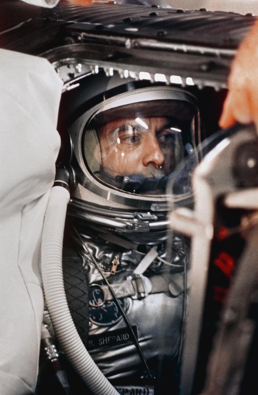
S88-31374 (29 April 1961) --- A close-up of astronaut Alan B. Shepard Jr. in his space suit with his helmet on inside the Mercury capsule. He is undergoing a flight simulation test with the capsule mated to the Redstone booster. This will be the first attempt to put a man into space by the U.S. aboard a Mercury spacecraft, launched atop a Redstone rocket. The suborbital trajectory will be down the Atlantic Missile Range. Photo credit: NASA or National Aeronautics and Space Administration
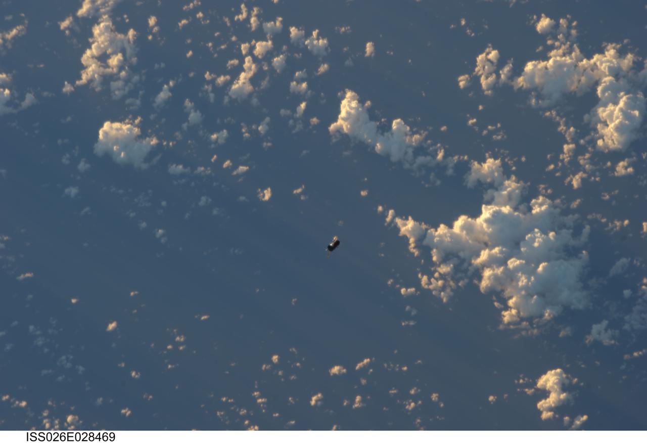
ISS026-E-028469 (20 Feb. 2011) --- Backdropped by a blue and white part of Earth, the unpiloted ISS Progress 39 supply vehicle appears to be very small as it departs from the International Space Station at 8:12 a.m. (EST) on Feb. 20, 2011. At 11:12 a.m., the deorbit burn braked the trash-loaded cargo ship into its re-entry trajectory over the Pacific Ocean, where it was burned up in Earth’s atmosphere.
![CAPE CANAVERAL, Fla. – The shipping crate is being removed from the STSS Demonstrator SV-1 spacecraft in the Astrotech payload processing facility in Titusville, Fla. The spacecraft is a midcourse tracking technology demonstrator, part of an evolving ballistic missile defense system. STSS is capable of tracking objects after boost phase and provides trajectory information to other sensors. It will be launched by NASA for the Missile Defense Agency in late summer. Photo credit: NASA/Tim Jacobs (Approved for Public Release 09-MDA-4800 [30 July 09] )](https://images-assets.nasa.gov/image/KSC-2009-4619/KSC-2009-4619~medium.jpg)
CAPE CANAVERAL, Fla. – The shipping crate is being removed from the STSS Demonstrator SV-1 spacecraft in the Astrotech payload processing facility in Titusville, Fla. The spacecraft is a midcourse tracking technology demonstrator, part of an evolving ballistic missile defense system. STSS is capable of tracking objects after boost phase and provides trajectory information to other sensors. It will be launched by NASA for the Missile Defense Agency in late summer. Photo credit: NASA/Tim Jacobs (Approved for Public Release 09-MDA-4800 [30 July 09] )
CAPE CANAVERAL, Fla. – On Launch Pad 17-B at Cape Canaveral Air Force Station, workers monitor the placement of a solid rocket booster on a Delta II rocket for launch of the STSS Demonstrator spacecraft. The spacecraft is a midcourse tracking technology demonstrator, part of an evolving ballistic missile defense system. STSS is capable of tracking objects after boost phase and provides trajectory information to other sensors. It will be launched by NASA for the Missile Defense Agency on July 29. Photo credit: NASA/Kim Shiflett

art001e002126 (Dec. 5, 2022) - The Moon is seen from cameras onboard NASA's Orion spacecraft during the 20th day of the Artemis I mission. These images were taken after Orion executed the Return Trajectory Correction 3 burn to prepare it for the Return Powered Flyby maneuver, bringing it on its second close approach to the lunar surface and continuing the journey back to Earth.
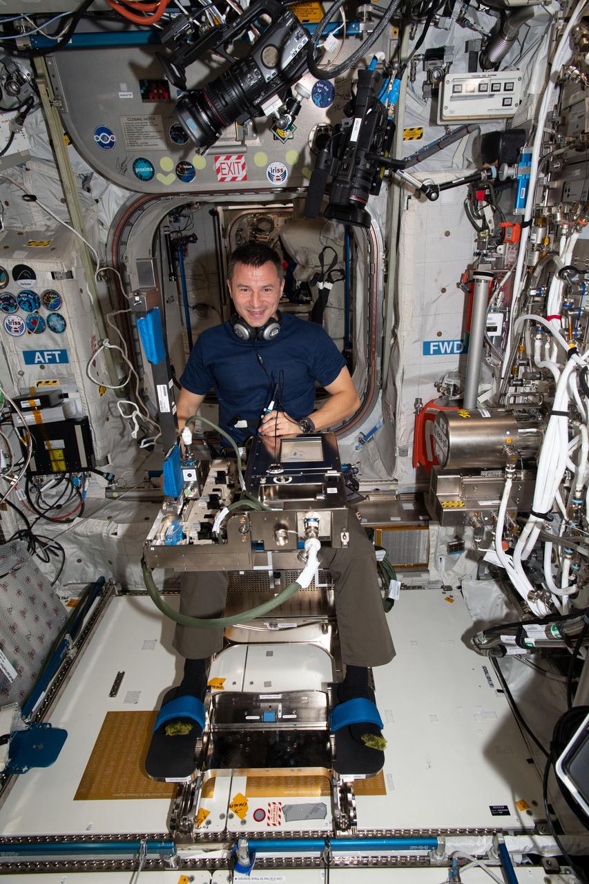
iss060e015011 (July 29, 2019) --- Expedition 60 Flight Engineer Andrew Morgan of NASA is in a seated configuration participating in the GRIP study. The experiment sponsored by the European Space Agency (ESA) observes how microgravity affects the abilities of astronauts to regulate grip force and upper limb trajectories when manipulating objects during a variety of movements. Morgan is conducting the scientific operations inside ESA's Columbus laboratory module.

jsc2024e016244 (11/27/2023) --- The final Multi-Resolution Scanning payload docked with an Astrobee robot at NASA’s Ames Research Center. The Multi-Resolution Scanning payload uses multiple different sensor types to generate high-resolution 3D data and more accurate trajectory data to understand how the robot moves around in 3D space. Such systems could support future Gateway and Lunar surface missions by providing automated defect detection, automated and remote maintenance, autonomous vehicle operations, and surface scanning using rovers.
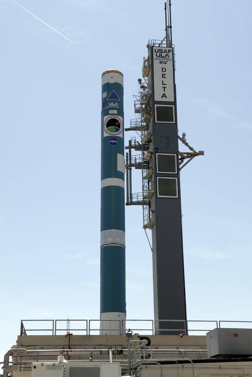
CAPE CANAVERAL, Fla. – On Launch Complex 17-B at Cape Canaveral Air Force Station, the first stage of the Delta II rocket waits on the gantry for the solid rocket boosters. The STSS Demonstrators is a midcourse tracking technology demonstrator and is part of an evolving ballistic missile defense system. STSS is capable of tracking objects after boost phase and provides trajectory information to other sensors. It will be launched by NASA for the Missile Defense Agency on July 29. Photo credit: NASA/Kim Shiflett
![CAPE CANAVERAL, Fla. – In the Astrotech payload processing facility in Titusville, Fla. , the STSS Demonstrator SV-1 spacecraft is lifted from its shipping crate. The spacecraft is a midcourse tracking technology demonstrator, part of an evolving ballistic missile defense system. STSS is capable of tracking objects after boost phase and provides trajectory information to other sensors. It will be launched by NASA for the Missile Defense Agency in late summer. Photo credit: NASA/Tim Jacobs (Approved for Public Release 09-MDA-4800 [30 July 09] )](https://images-assets.nasa.gov/image/KSC-2009-4620/KSC-2009-4620~medium.jpg)
CAPE CANAVERAL, Fla. – In the Astrotech payload processing facility in Titusville, Fla. , the STSS Demonstrator SV-1 spacecraft is lifted from its shipping crate. The spacecraft is a midcourse tracking technology demonstrator, part of an evolving ballistic missile defense system. STSS is capable of tracking objects after boost phase and provides trajectory information to other sensors. It will be launched by NASA for the Missile Defense Agency in late summer. Photo credit: NASA/Tim Jacobs (Approved for Public Release 09-MDA-4800 [30 July 09] )
![CAPE CANAVERAL, Fla. – In the Astrotech payload processing facility in Titusville, Fla. , the STSS Demonstrator SV-1 spacecraft is lowered toward the orbital insertion system. The spacecraft is a midcourse tracking technology demonstrator, part of an evolving ballistic missile defense system. STSS is capable of tracking objects after boost phase and provides trajectory information to other sensors. It will be launched by NASA for the Missile Defense Agency in late summer. Photo credit: NASA/Tim Jacobs (Approved for Public Release 09-MDA-4800 [30 July 09] )](https://images-assets.nasa.gov/image/KSC-2009-4625/KSC-2009-4625~medium.jpg)
CAPE CANAVERAL, Fla. – In the Astrotech payload processing facility in Titusville, Fla. , the STSS Demonstrator SV-1 spacecraft is lowered toward the orbital insertion system. The spacecraft is a midcourse tracking technology demonstrator, part of an evolving ballistic missile defense system. STSS is capable of tracking objects after boost phase and provides trajectory information to other sensors. It will be launched by NASA for the Missile Defense Agency in late summer. Photo credit: NASA/Tim Jacobs (Approved for Public Release 09-MDA-4800 [30 July 09] )
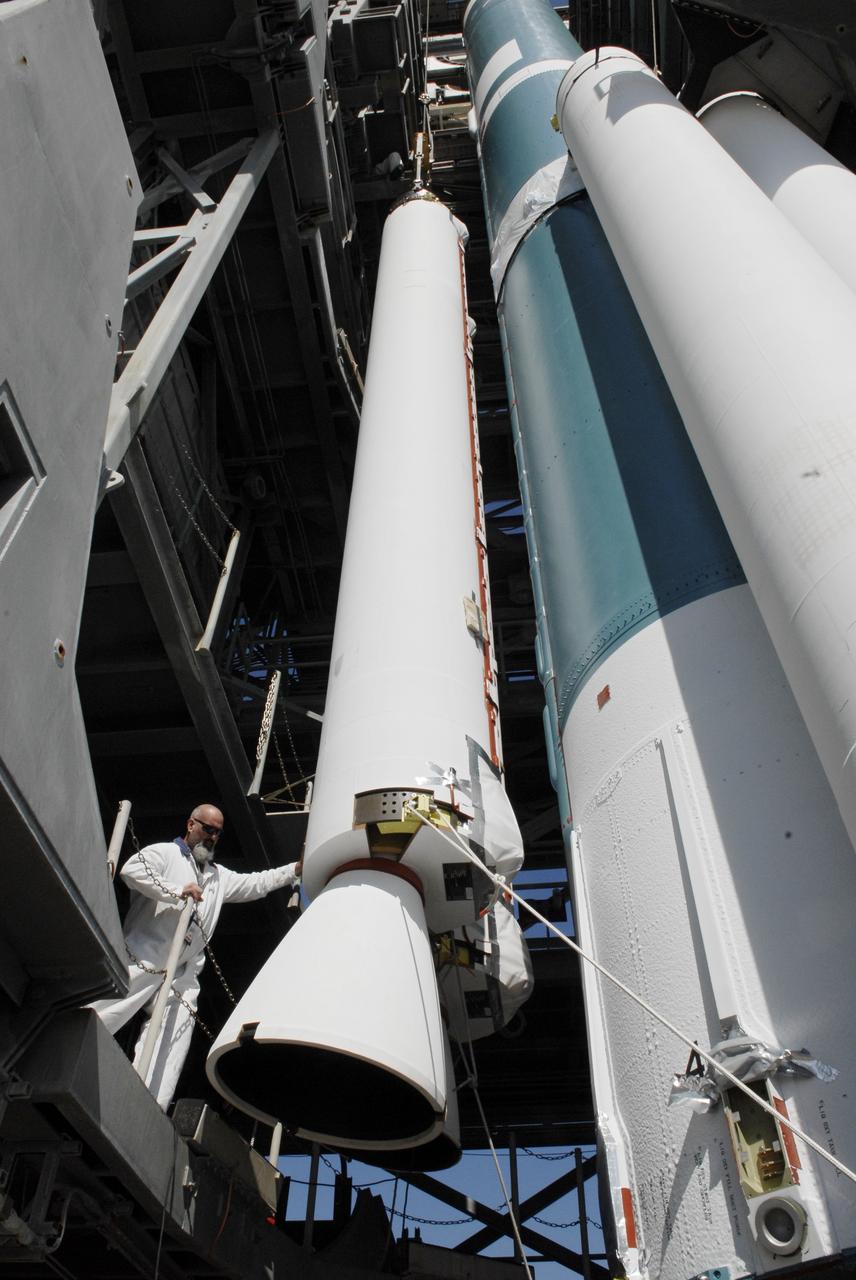
CAPE CANAVERAL, Fla. – On Launch Pad 17-B at Cape Canaveral Air Force Station, a worker monitors the placement of a solid rocket booster on a Delta II rocket for launch of the STSS Demonstrator spacecraft. The spacecraft is a midcourse tracking technology demonstrator, part of an evolving ballistic missile defense system. STSS is capable of tracking objects after boost phase and provides trajectory information to other sensors. It will be launched by NASA for the Missile Defense Agency on July 29. Photo credit: NASA/Kim Shiflett

art001e002128 Dec. 5, 2022 A portion of the Moon looms large just beyond the Orion spacecraft in this image taken on the 20th day of the Artemis I mission by a camera on the tip of one of Orion’s solar arrays. The return powered flyby burn committed Orion to a return to Earth trajectory ahead of a splashdown off the coast of California on Dec. 11. At its closest point, Orion flew within 80 miles of the lunar surface.
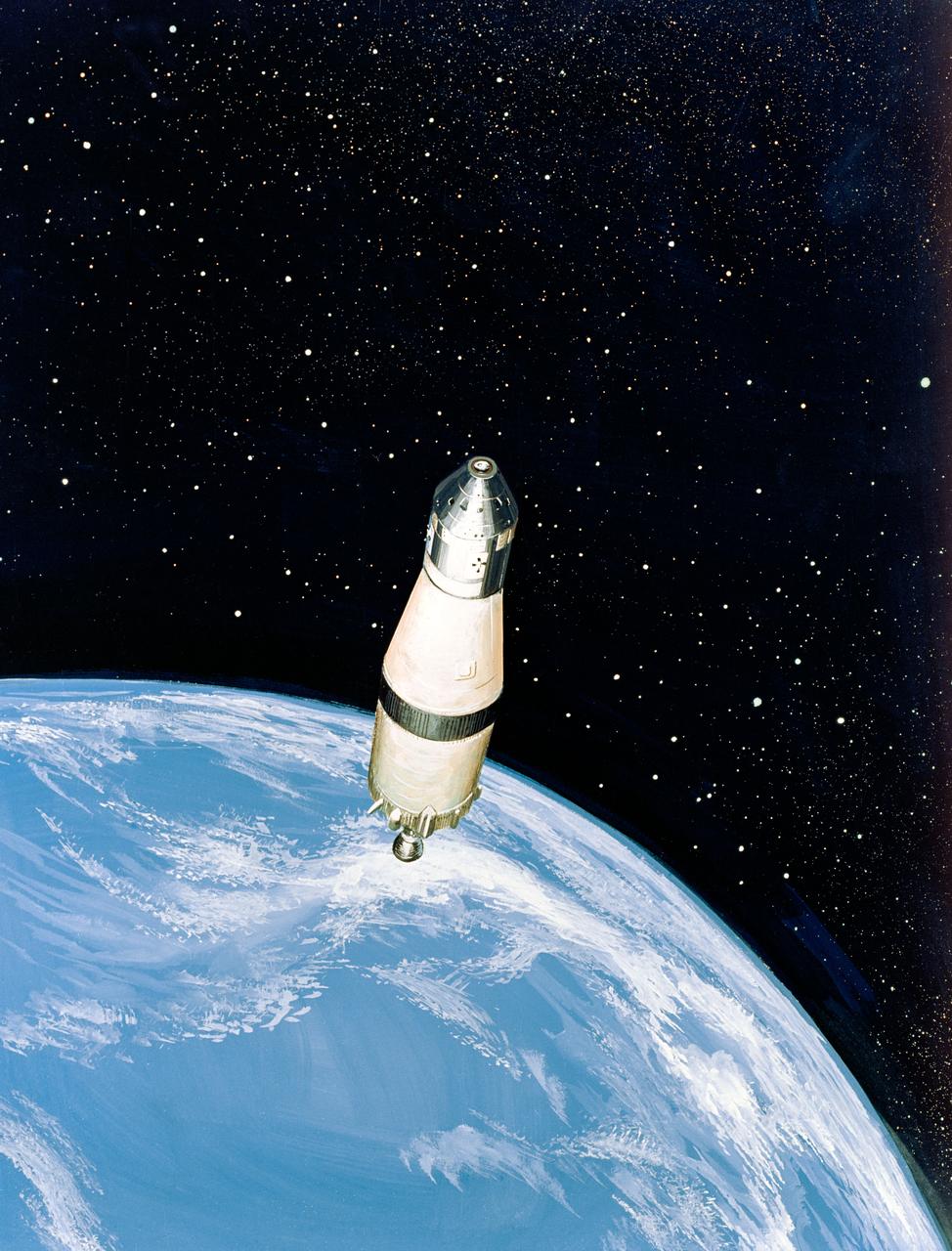
S68-51304 (December 1968) --- North American Rockwell artist's concept illustrating a phase of the scheduled Apollo 8 lunar orbit mission. Here, the Apollo 8 spacecraft Command and Service Modules (CSM), still attached to the Saturn V (S-IVB) third stage, heads for the moon at a speed of about 24,300 miles per hour. The trajectory, computed from the Saturn V's third stage instrumentation unit, provides a "free return" to Earth around the moon.
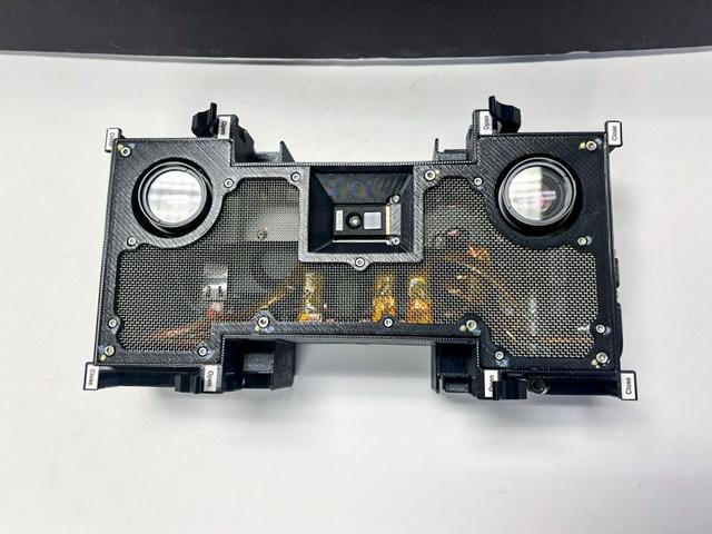
jsc2024e016243 (2/14/2024) --- Close-up view of the final Multi-Resolution Scanning payload with its stereo vision cameras at left and right. The Multi-Resolution Scanning payload uses multiple different sensor types to generate high-resolution 3D data and more accurate trajectory data to understand how the Astrobee robot moves around in 3D space.
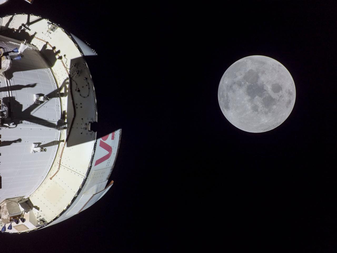
art001e002104 (Dec. 5, 2022) - The Moon is seen from cameras onboard NASA's Orion spacecraft during the 20th day of the Artemis I mission. These images were taken after Orion executed the Return Trajectory Correction 3 burn to prepare it for the Return Powered Flyby maneuver, bringing it on its second close approach to the lunar surface and continuing the journey back to Earth.
![CAPE CANAVERAL, Fla. – The STSS Demonstrator SV-2spacecraft is moved inside a building at the Astrotech payload processing facility in Titusville, Fla. The spacecraft is a midcourse tracking technology demonstrator, part of an evolving ballistic missile defense system. STSS is capable of tracking objects after boost phase and provides trajectory information to other sensors. It will be launched by NASA for the Missile Defense Agency in late summer. Photo credit: NASA/Jack Pfaller (Approved for Public Release 09-MDA-4616 [27 May 09])](https://images-assets.nasa.gov/image/KSC-2009-3668/KSC-2009-3668~medium.jpg)
CAPE CANAVERAL, Fla. – The STSS Demonstrator SV-2spacecraft is moved inside a building at the Astrotech payload processing facility in Titusville, Fla. The spacecraft is a midcourse tracking technology demonstrator, part of an evolving ballistic missile defense system. STSS is capable of tracking objects after boost phase and provides trajectory information to other sensors. It will be launched by NASA for the Missile Defense Agency in late summer. Photo credit: NASA/Jack Pfaller (Approved for Public Release 09-MDA-4616 [27 May 09])
![CAPE CANAVERAL, Fla. – In the Astrotech payload processing facility in Titusville, Fla. , technicians monitor the STSS Demonstrator SV-1 spacecraft as it is lowered to the orbital insertion system. The spacecraft is a midcourse tracking technology demonstrator, part of an evolving ballistic missile defense system. STSS is capable of tracking objects after boost phase and provides trajectory information to other sensors. It will be launched by NASA for the Missile Defense Agency in late summer. Photo credit: NASA/Tim Jacobs (Approved for Public Release 09-MDA-4800 [30 July 09] )](https://images-assets.nasa.gov/image/KSC-2009-4626/KSC-2009-4626~medium.jpg)
CAPE CANAVERAL, Fla. – In the Astrotech payload processing facility in Titusville, Fla. , technicians monitor the STSS Demonstrator SV-1 spacecraft as it is lowered to the orbital insertion system. The spacecraft is a midcourse tracking technology demonstrator, part of an evolving ballistic missile defense system. STSS is capable of tracking objects after boost phase and provides trajectory information to other sensors. It will be launched by NASA for the Missile Defense Agency in late summer. Photo credit: NASA/Tim Jacobs (Approved for Public Release 09-MDA-4800 [30 July 09] )
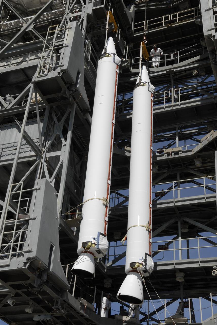
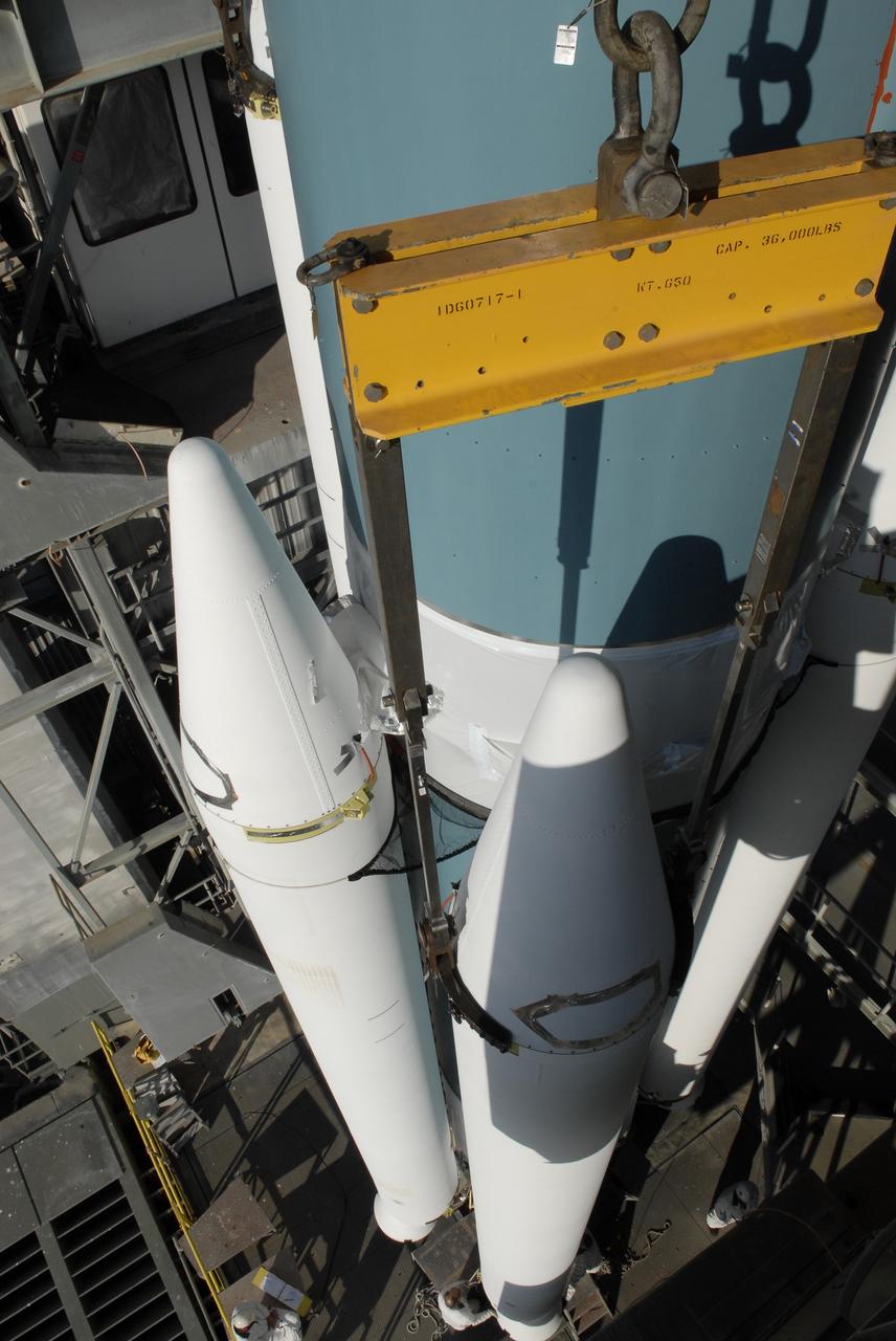
CAPE CANAVERAL, Fla. – On Launch Complex 17-B at Cape Canaveral Air Force Station, solid rocket boosters are lifted into the mobile service tower. The boosters will be attached to the Delta II rocket that will launch the STSS Demonstrator spacecraft. The STSS Demonstrators is a midcourse tracking technology demonstrator and is part of an evolving ballistic missile defense system. STSS is capable of tracking objects after boost phase and provides trajectory information to other sensors. It will be launched by NASA for the Missile Defense Agency on July 29. Photo credit: NASA/Kim Shiflett

ISS026-E-028490 (20 Feb. 2011) --- Backdropped by a blue and white part of Earth, the unpiloted ISS Progress 39 supply vehicle appears to be very small as it departs from the International Space Station at 8:12 a.m. (EST) on Feb. 20, 2011. At 11:12 a.m., the deorbit burn braked the trash-loaded cargo ship into its re-entry trajectory over the Pacific Ocean, where it was burned up in Earth’s atmosphere.
![CAPE CANAVERAL, Fla. – In the Astrotech payload processing facility in Titusville, Fla. , the STSS Demonstrator SV-1 spacecraft is moved toward the orbital insertion system. The spacecraft is a midcourse tracking technology demonstrator, part of an evolving ballistic missile defense system. STSS is capable of tracking objects after boost phase and provides trajectory information to other sensors. It will be launched by NASA for the Missile Defense Agency in late summer. Photo credit: NASA/Tim Jacobs (Approved for Public Release 09-MDA-4800 [30 July 09] )](https://images-assets.nasa.gov/image/KSC-2009-4624/KSC-2009-4624~medium.jpg)
CAPE CANAVERAL, Fla. – In the Astrotech payload processing facility in Titusville, Fla. , the STSS Demonstrator SV-1 spacecraft is moved toward the orbital insertion system. The spacecraft is a midcourse tracking technology demonstrator, part of an evolving ballistic missile defense system. STSS is capable of tracking objects after boost phase and provides trajectory information to other sensors. It will be launched by NASA for the Missile Defense Agency in late summer. Photo credit: NASA/Tim Jacobs (Approved for Public Release 09-MDA-4800 [30 July 09] )
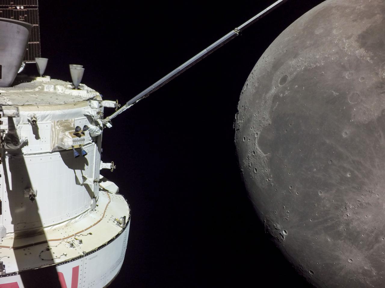
art001e002130 Dec. 5, 2022 A portion of the Moon looms large just beyond the Orion spacecraft in this image taken on the 20th day of the Artemis I mission by a camera on the tip of one of Orion’s solar arrays. The return powered flyby burn committed Orion to a return to Earth trajectory ahead of a splashdown off the coast of California on Dec. 11. At its closest point, Orion flew within 80 miles of the lunar surface.
CAPE CANAVERAL, Fla. – On Launch Pad 17-B at Cape Canaveral Air Force Station, solid rocket boosters are attached to a Delta II rocket for launch of the STSS Demonstrator spacecraft. The spacecraft is a midcourse tracking technology demonstrator, part of an evolving ballistic missile defense system. STSS is capable of tracking objects after boost phase and provides trajectory information to other sensors. It will be launched by NASA for the Missile Defense Agency on July 29. Photo credit: NASA/Kim Shiflett

S70-35368 (16 April 1970) --- Overall view showing some of the feverish activity in the Mission Operations Control Room (MOCR) of the Mission Control Center (MCC) during the final 24 hours of the problem-plagued Apollo 13 mission. Here, flight controllers and several NASA/MSC officials confer at the flight director's console. When this picture was made, the Apollo 13 lunar landing had already been canceled, and the Apollo 13 crewmembers were in trans-Earth trajectory attempting to bring their crippled spacecraft back home.
![CAPE CANAVERAL, Fla. – In the Astrotech payload processing facility in Titusville, Fla. , the STSS Demonstrator SV-1 spacecraft is lowered to the orbital insertion system. The spacecraft is a midcourse tracking technology demonstrator, part of an evolving ballistic missile defense system. STSS is capable of tracking objects after boost phase and provides trajectory information to other sensors. It will be launched by NASA for the Missile Defense Agency in late summer. Photo credit: NASA/Tim Jacobs (Approved for Public Release 09-MDA-4800 [30 July 09] )](https://images-assets.nasa.gov/image/KSC-2009-4628/KSC-2009-4628~medium.jpg)
CAPE CANAVERAL, Fla. – In the Astrotech payload processing facility in Titusville, Fla. , the STSS Demonstrator SV-1 spacecraft is lowered to the orbital insertion system. The spacecraft is a midcourse tracking technology demonstrator, part of an evolving ballistic missile defense system. STSS is capable of tracking objects after boost phase and provides trajectory information to other sensors. It will be launched by NASA for the Missile Defense Agency in late summer. Photo credit: NASA/Tim Jacobs (Approved for Public Release 09-MDA-4800 [30 July 09] )
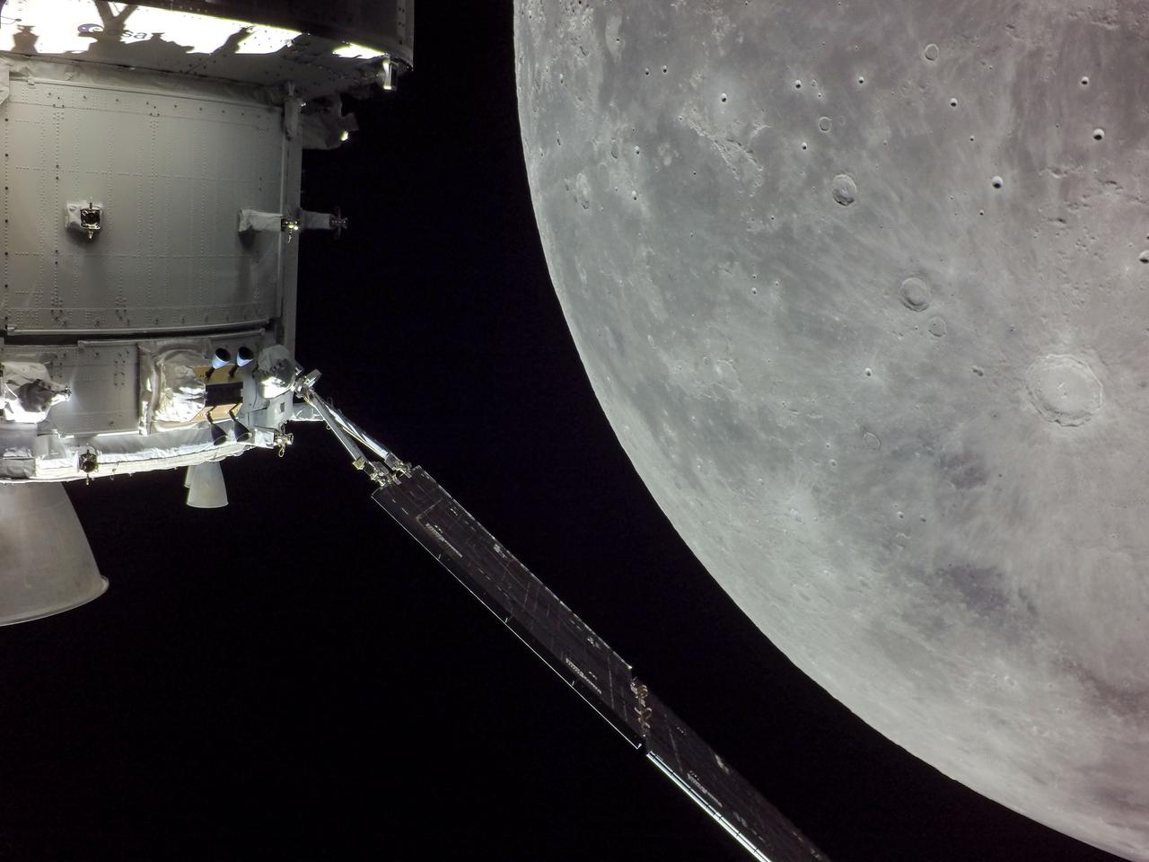
art001e002131 (Dec. 5, 2022) A portion of the Moon looms large just beyond the Orion spacecraft in this image taken on the 20th day of the Artemis I mission by a camera on the tip of one of Orion’s solar arrays. The return powered flyby burn committed Orion to a return to Earth trajectory ahead of a splashdown off the coast of California on Dec. 11. At its closest point, Orion flew within 80 miles of the lunar surface.
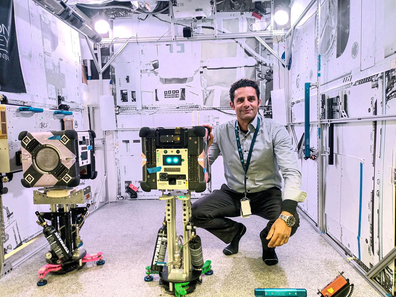
jsc2024e016241 (11/17/2023) --- CSIRO Project Lead Dr. Marc Elmouttie with the Multi-Resolution Scanning payload, housed.within an Astrobee robot. The Multi-Resolution Scanning payload uses multiple different sensor types to generate high-resolution 3D data and more accurate trajectory data to understand how the robot moves around in 3D space. Image courtesy of CSIRO.
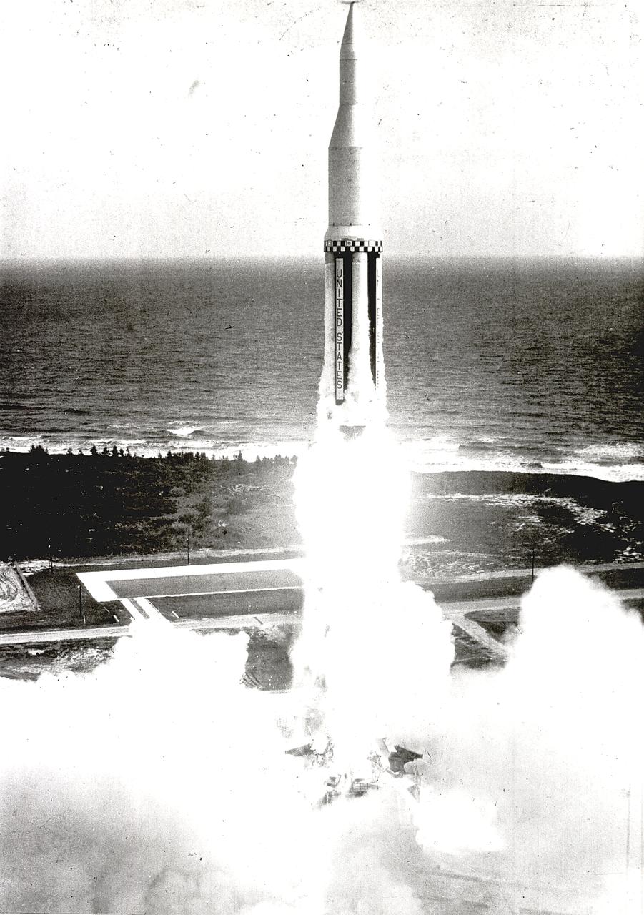
On October 27, 1961, the Marshall Space Flight Center and the Nation marked a high point in the 3-year-old Saturn development program when the first Saturn vehicle flew a flawless 215-mile ballistic trajectory from Cape Canaveral, Florida. The 162-foot-tall rocket weighed 925,000 pounds and employed a dummy second stage.
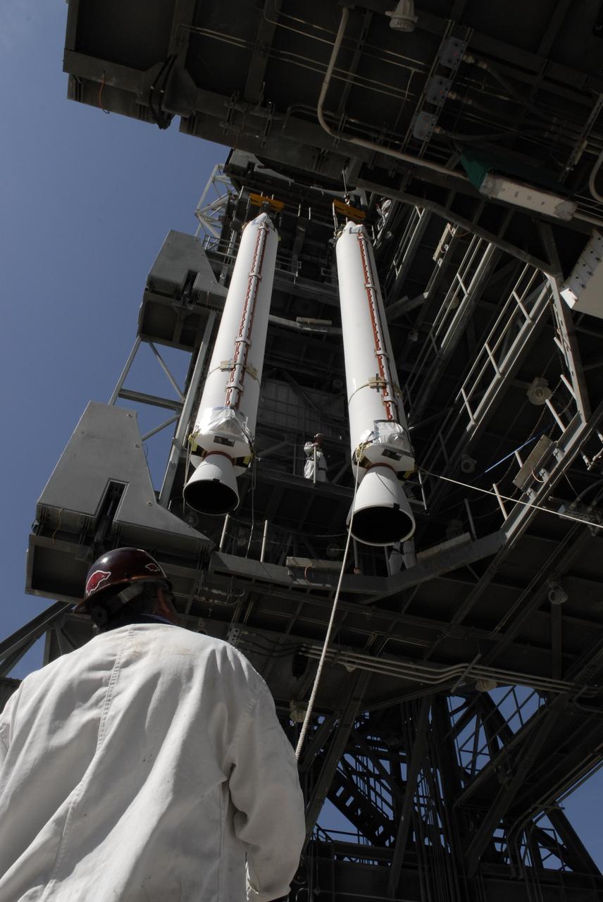
CAPE CANAVERAL, Fla. – On Launch Complex 17-B at Cape Canaveral Air Force Station, solid rocket boosters are lifted into the mobile service tower. The boosters will be attached to the Delta II rocket that will launch the STSS Demonstrator spacecraft. The STSS Demonstrators is a midcourse tracking technology demonstrator and is part of an evolving ballistic missile defense system. STSS is capable of tracking objects after boost phase and provides trajectory information to other sensors. It will be launched by NASA for the Missile Defense Agency on July 29. Photo credit: NASA/Kim Shiflett
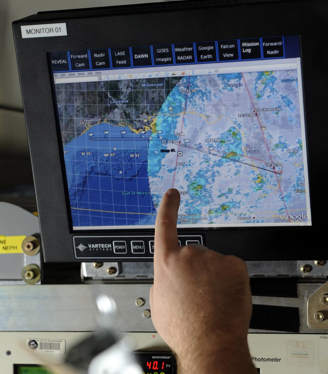
A researcher points out the trajectory of a weather pattern on a computer monitor during a flight aboard the NASA DC-8 aircraft, Tuesday, Aug. 17, 2010, over the Gulf of Mexico. Sceintists and researchers flew Tuesday to study weather as part of the Genesis and Rapid Intensification Processes (GRIP) experiment is a NASA Earth science field experiment in 2010 that is being conducted to better understand how tropical storms form and develop into major hurricanes. Photo Credit: (NASA/Paul E. Alers)