
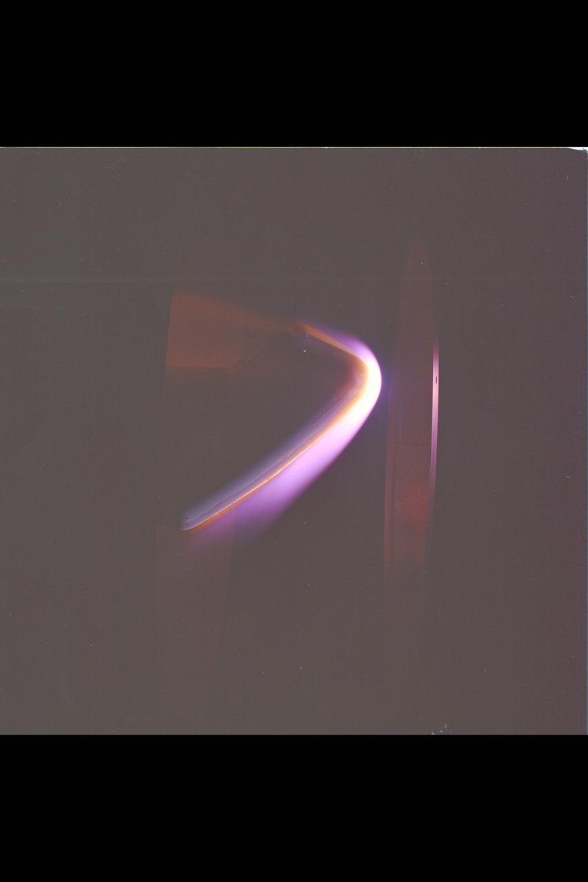
A test block of Avcoat undergoes heat pulse testing inside an arc jet test chamber at NASA’s Ames Research Center in California. The test article, configured with both permeable (upper) and non-permeable (lower) Avcoat sections for comparison, helped to confirm understanding of the root cause of the loss of charred Avcoat material that engineers saw on the Orion spacecraft after the Artemis I test flight beyond the Moon.
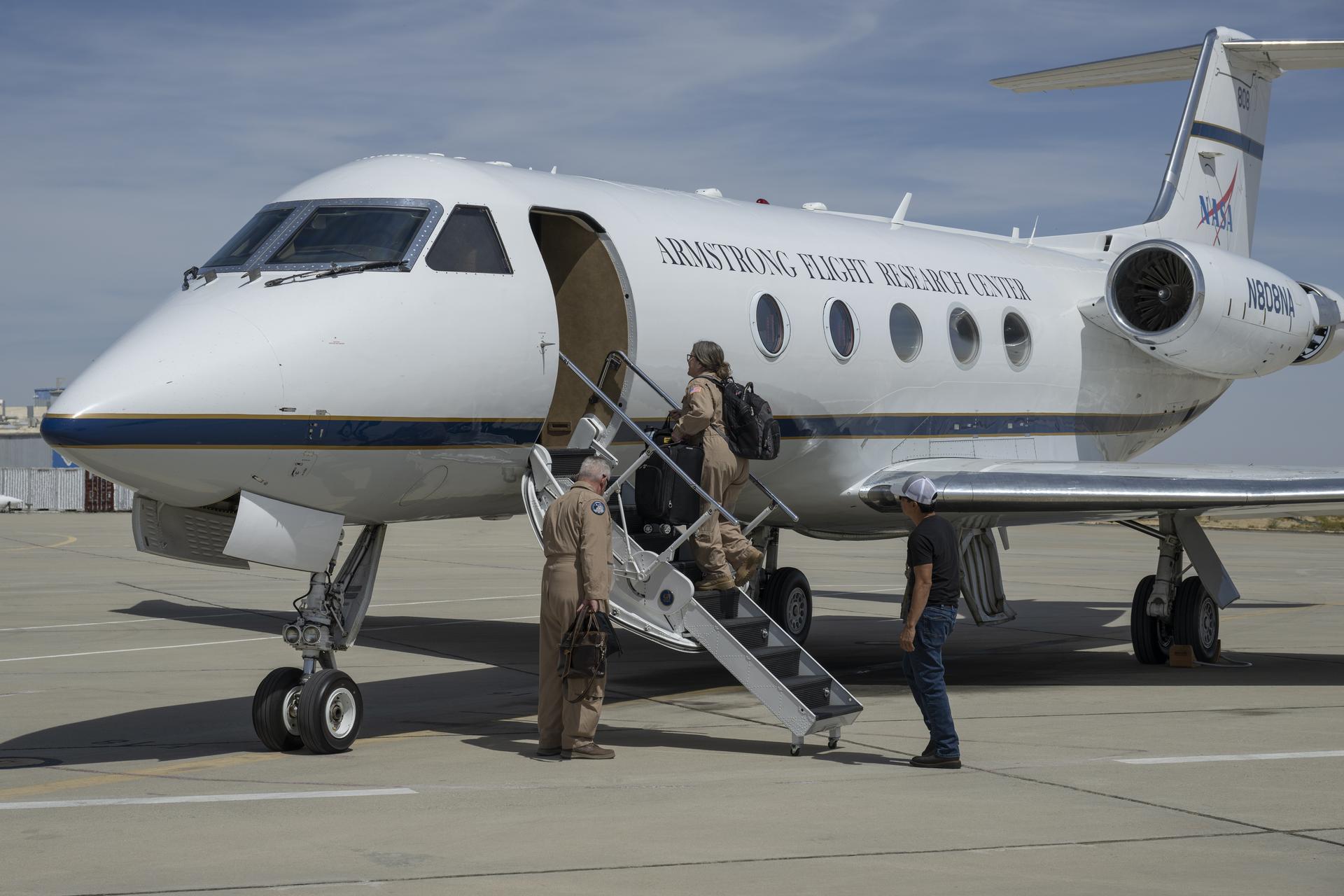
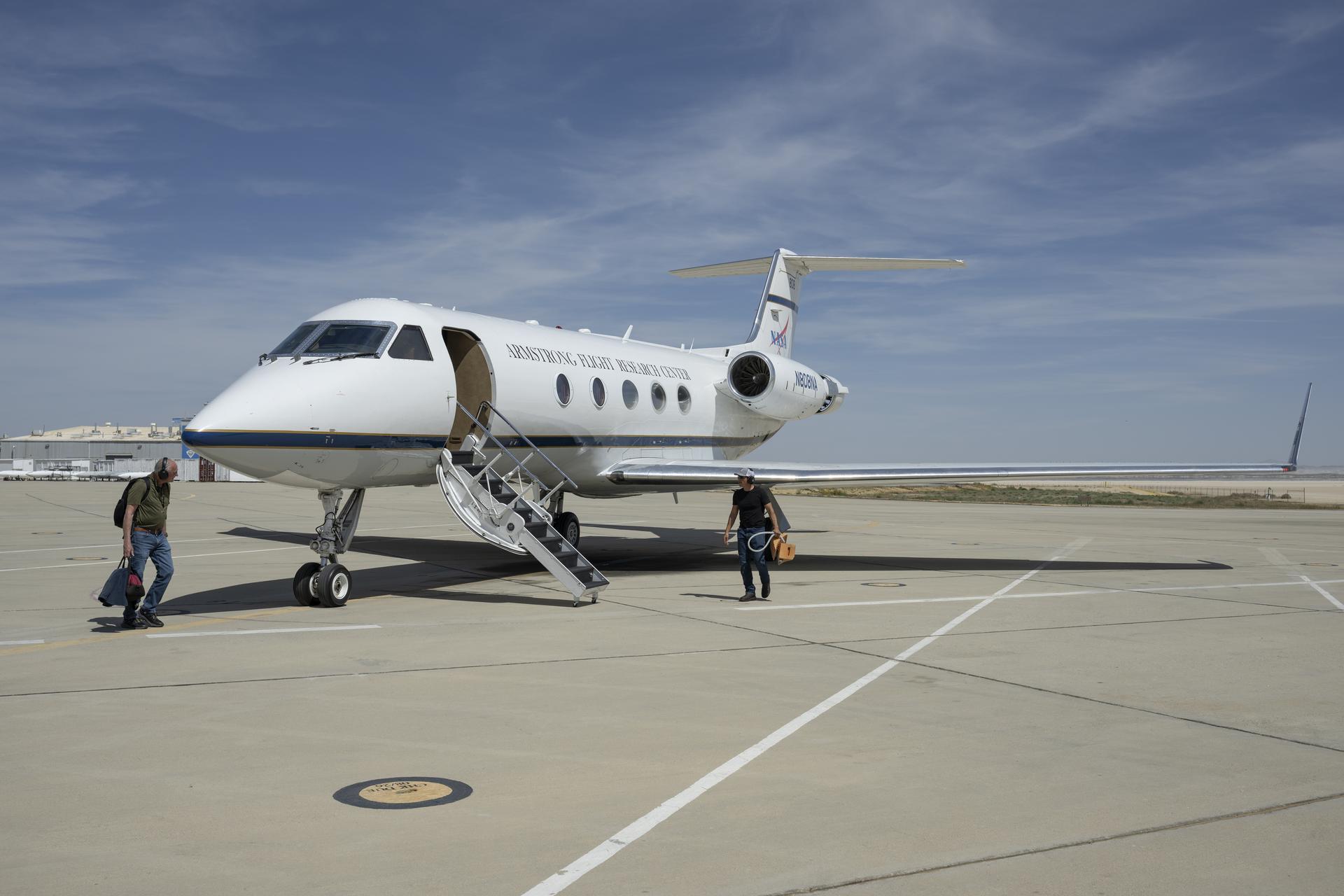
NASA pilot Carrie Worth, center, and Tracy Phelps, left, board the Gulfstream G-III aircraft on Friday, March 27, 2026, at NASA’s Armstrong Flight Research Center in Edwards, California. Manny Rodriguez, crew chief, prepares the aircraft for flight. The G-III will join other NASA aircraft to capture imagery of the Orion spacecraft’s heat shield during Artemis II reentry. The mission is part of NASA’s Scientifically Calibrated In-Flight Imagery (SCIFLI) project, based at NASA’s Langley Research Center in Hampton, Virginia.
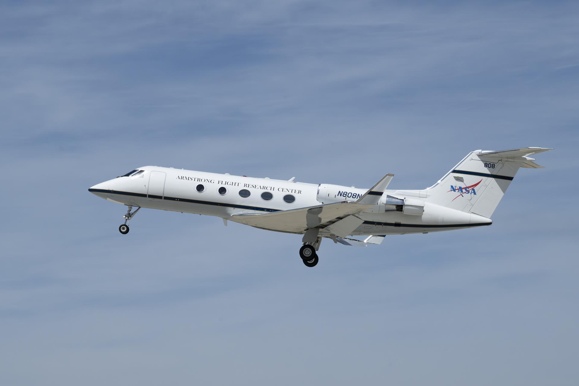
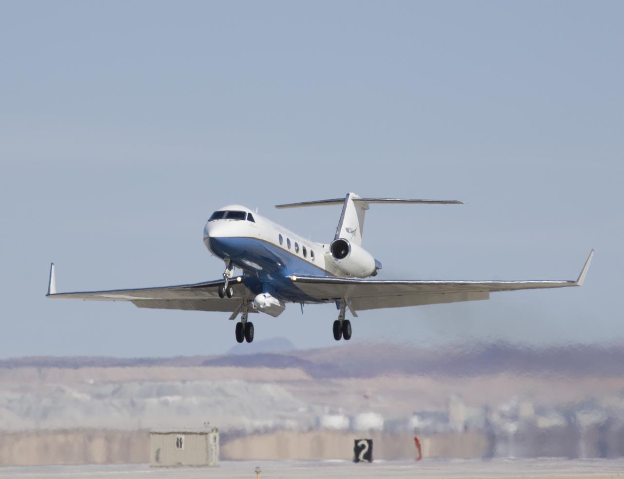
A Gulfstream G-III takes off Friday, March 27, 2026, from NASA’s Armstrong Flight Research Center in Edwards, California. The G-III will join other NASA aircraft to capture imagery of the Orion spacecraft’s heat shield during Artemis II reentry. The mission is part of NASA’s Scientifically Calibrated In-Flight Imagery (SCIFLI) project, based at NASA’s Langley Research Center in Hampton, Virginia.

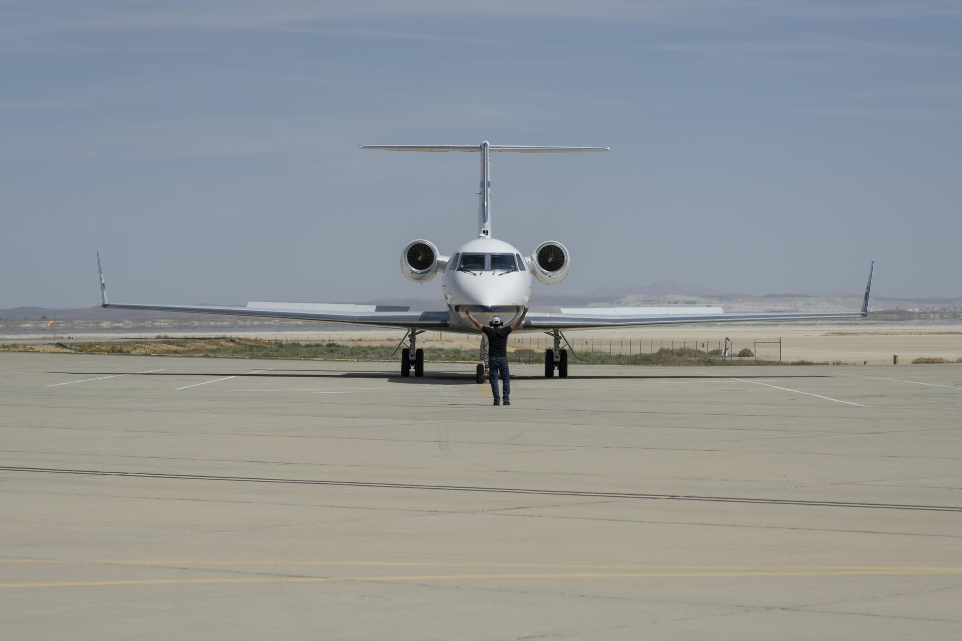
NASA pilot Tracy Phelps inspects the Gulfstream G-III aircraft on Friday, March 27, 2026, at NASA’s Armstrong Flight Research Center in Edwards, California. The G-III will join other NASA aircraft to capture imagery of the Orion spacecraft’s heat shield during Artemis II reentry. The mission is part of NASA’s Scientifically Calibrated In-Flight Imagery (SCIFLI) project, based at NASA’s Langley Research Center in Hampton, Virginia.
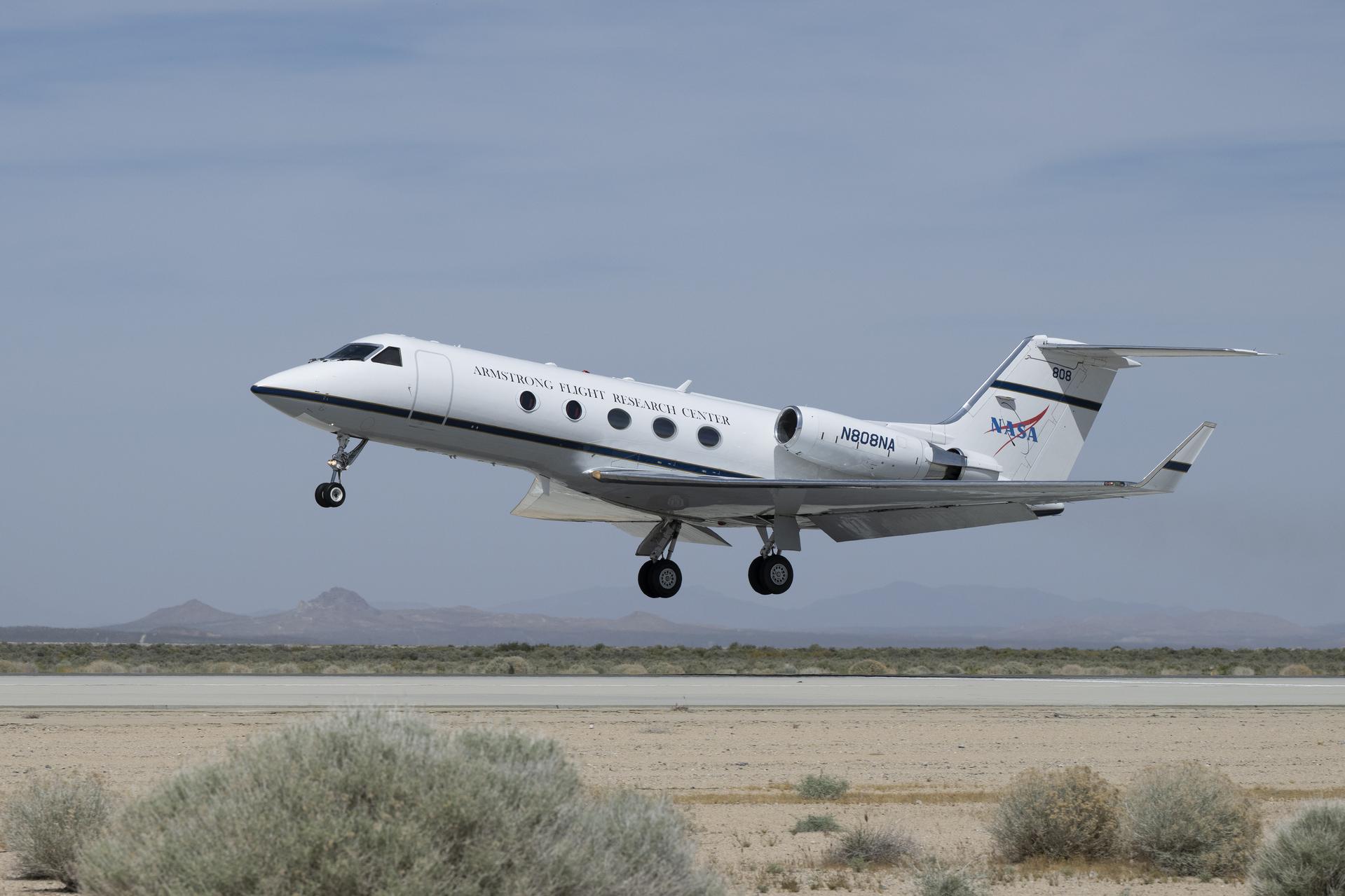
A Gulfstream G-III takes off Friday, March 27, 2026, from NASA’s Armstrong Flight Research Center in Edwards, California. The G-III will join other NASA aircraft to capture imagery of the Orion spacecraft’s heat shield during Artemis II reentry. The mission is part of NASA’s Scientifically Calibrated In-Flight Imagery (SCIFLI) project, based at NASA’s Langley Research Center in Hampton, Virginia.
Manny Rodriguez, Gulfstream G-III crew chief, completes flight control checks with the pilots on Friday, March 27, 2026, at NASA’s Armstrong Flight Research Center in Edwards, California. The G-III will join other NASA aircraft to capture imagery of the Orion spacecraft’s heat shield during Artemis II reentry. The mission is part of NASA’s Scientifically Calibrated In-Flight Imagery (SCIFLI) project, based at NASA’s Langley Research Center in Hampton, Virginia.
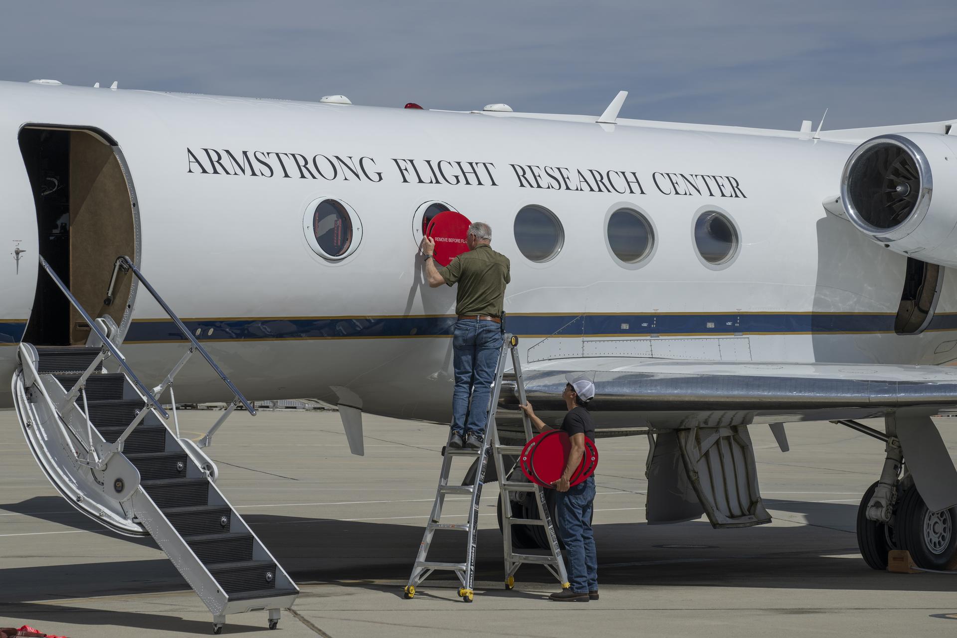
Scott Erickson, left, a quality assurance inspector, and Manny Rodriguez, Gulfstream G-III aircraft crew chief, remove window coverings from the aircraft on Friday, March 27, 2026, at NASA’s Armstrong Flight Research Center in Edwards, California. The G-III will join other NASA aircraft to capture imagery of the Orion spacecraft’s heat shield during Artemis II reentry. The mission is part of NASA’s Scientifically Calibrated In-Flight Imagery (SCIFLI) project, based at NASA’s Langley Research Center in Hampton, Virginia.
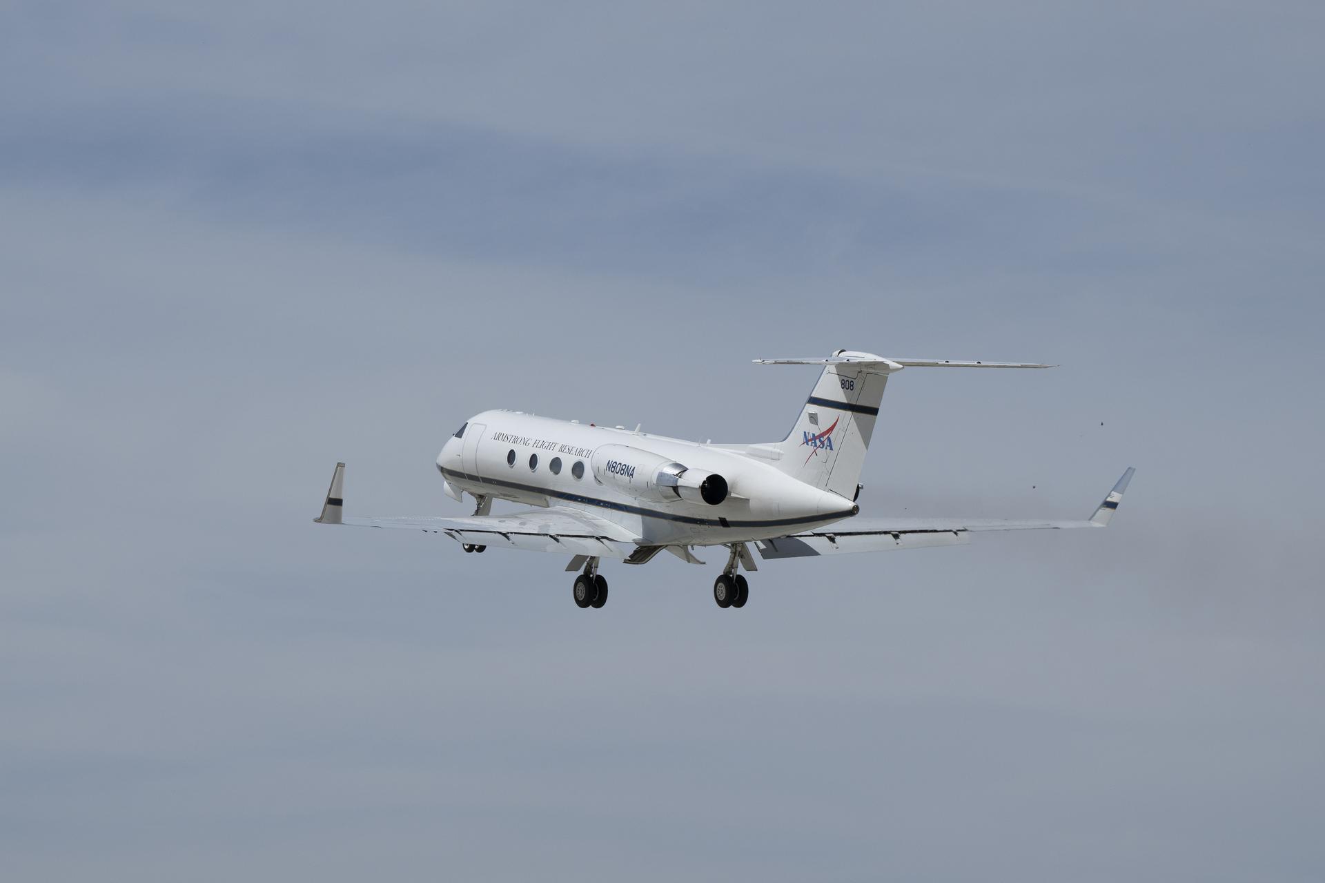
A Gulfstream G-III takes off Friday, March 27, 2026, from NASA’s Armstrong Flight Research Center in Edwards, California. The G-III will join other NASA aircraft to capture imagery of the Orion spacecraft’s heat shield during Artemis II reentry. The mission is part of NASA’s Scientifically Calibrated In-Flight Imagery (SCIFLI) project, based at NASA’s Langley Research Center in Hampton, Virginia.
Scott Erickson, left, a quality assurance inspector, and Manny Rodriguez, Gulfstream G-III crew chief, prepare the aircraft for flight on Friday, March 27, 2026, at NASA’s Armstrong Flight Research Center in Edwards, California. The G-III will join other NASA aircraft to capture imagery of the Orion spacecraft’s heat shield during Artemis II reentry. The mission is part of NASA’s Scientifically Calibrated In-Flight Imagery (SCIFLI) project, based at NASA’s Langley Research Center in Hampton, Virginia.
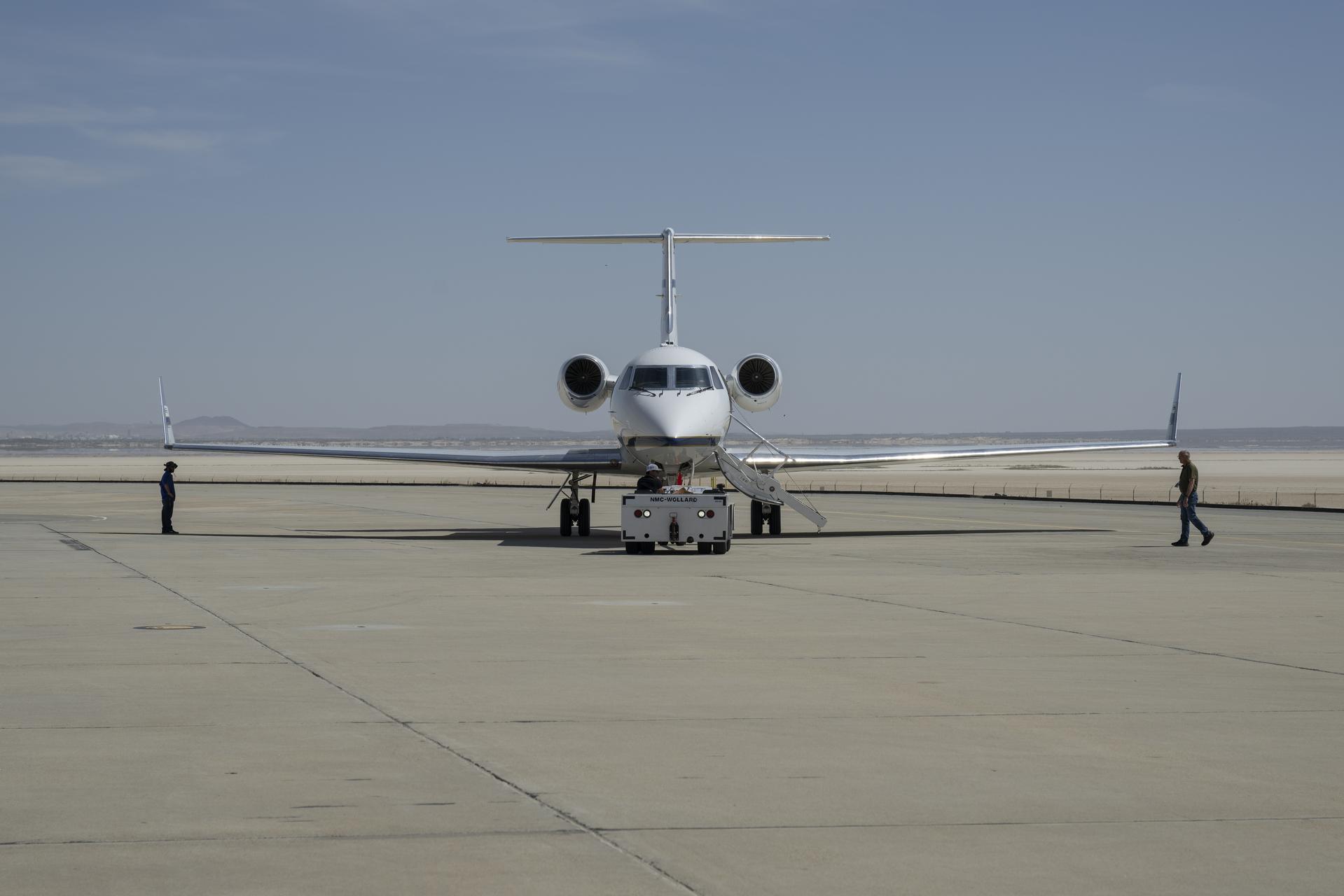
Manny Rodriguez, center, Gulfstream G-III aircraft crew chief, drives a tug while mechanic Marlon Espinoza, left, and Scott Erickson, a quality assurance inspector, prepare the aircraft for takeoff on Friday, March 27, 2026, at NASA’s Armstrong Flight Research Center in Edwards, California. The G-III will join other NASA aircraft to capture imagery of the Orion spacecraft’s heat shield during Artemis II reentry. The mission is part of NASA’s Scientifically Calibrated In-Flight Imagery (SCIFLI) project, based at NASA’s Langley Research Center in Hampton, Virginia.
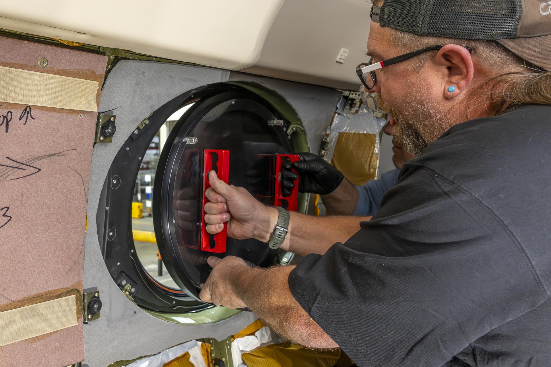
Aircraft mechanic Brian Harness, left, and mechanic Eric Apikian install a temporary aircraft window on a NASA Gulfstream G-III aircraft on Wednesday, Jan. 7, 2026, at NASA’s Armstrong Flight Research Center in Edwards, California. The modifications prepare the aircraft to join three others flying at different altitudes to capture a complete view of the Orion spacecraft’s heat shield during Artemis II reentry. This effort is part of NASA’s Scientifically Calibrated In-Flight Imagery project.
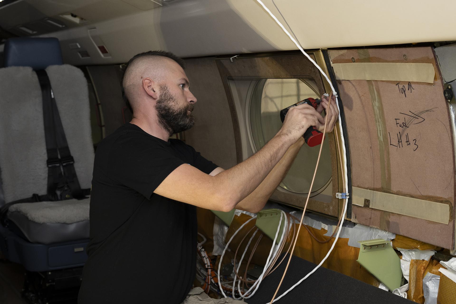
Kelly Jellison, an avionics lead, installs a clip to secure wiring installed on a NASA Gulfstream G-III aircraft on Wednesday, Jan. 7, 2026, at NASA’s Armstrong Flight Research Center in Edwards, California. The modifications prepare the aircraft to join three others flying at different altitudes to capture a complete view of the Orion spacecraft’s heat shield during Artemis II reentry. This effort is part of NASA’s Scientifically Calibrated In-Flight Imagery project.
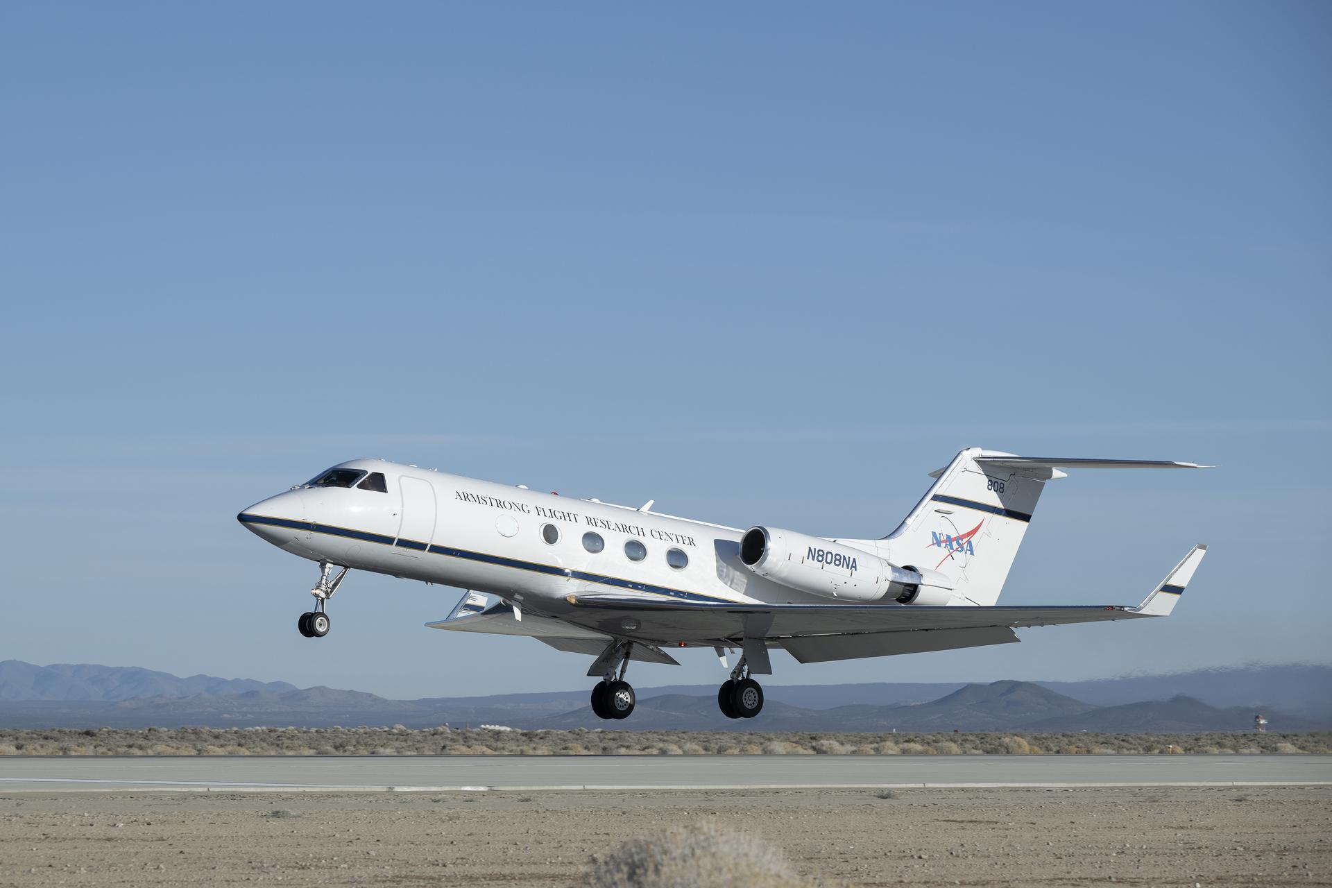
A NASA Gulfstream G-III aircraft lifts off from NASA’s Armstrong Flight Research Center in Edwards, California, on Tuesday, Jan. 20, 2026. Modifications were made to the aircraft to enable it to join three others flying at different altitudes to capture a complete view of the Orion spacecraft’s heat shield during Artemis II reentry. This effort is part of NASA’s Scientifically Calibrated In-Flight Imagery project.

A NASA Gulfstream G-III aircraft lifts off from NASA’s Armstrong Flight Research Center in Edwards, California, on Tuesday, Jan. 20, 2026. Modifications were made to the aircraft to enable it to join three others flying at different altitudes to capture a complete view of the Orion spacecraft’s heat shield during Artemis II reentry. This effort is part of NASA’s Scientifically Calibrated In-Flight Imagery project.
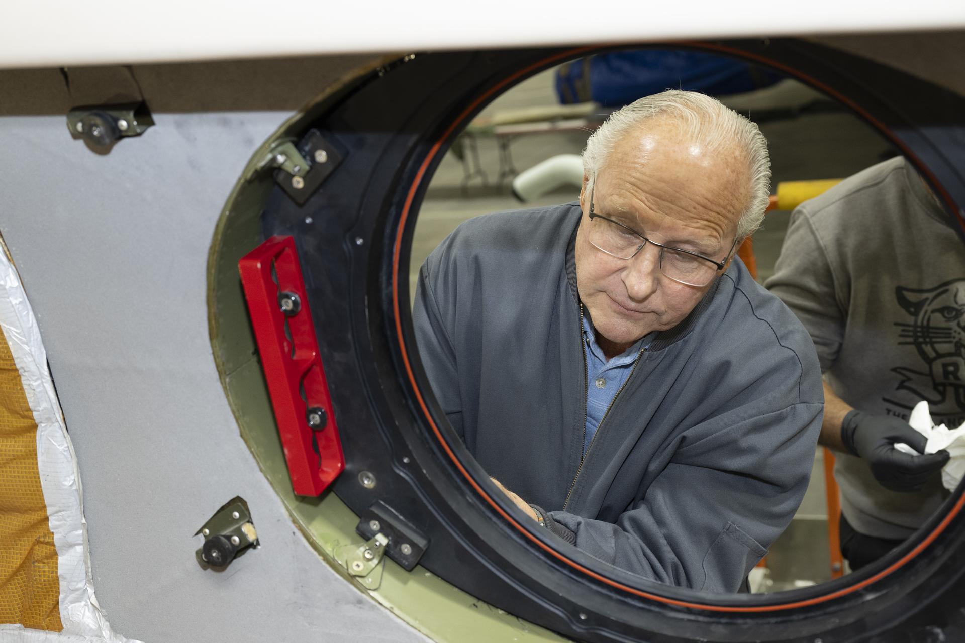
Scott Erickson, a quality assurance inspector, reviews installation of a temporary aircraft window on a NASA Gulfstream G-III aircraft on Wednesday, Jan. 7, 2026, at NASA’s Armstrong Flight Research Center in Edwards, California. The modifications prepare the aircraft to join three others flying at different altitudes to capture a complete view of the Orion spacecraft’s heat shield during Artemis II reentry. This effort is part of NASA’s Scientifically Calibrated In-Flight Imagery project.
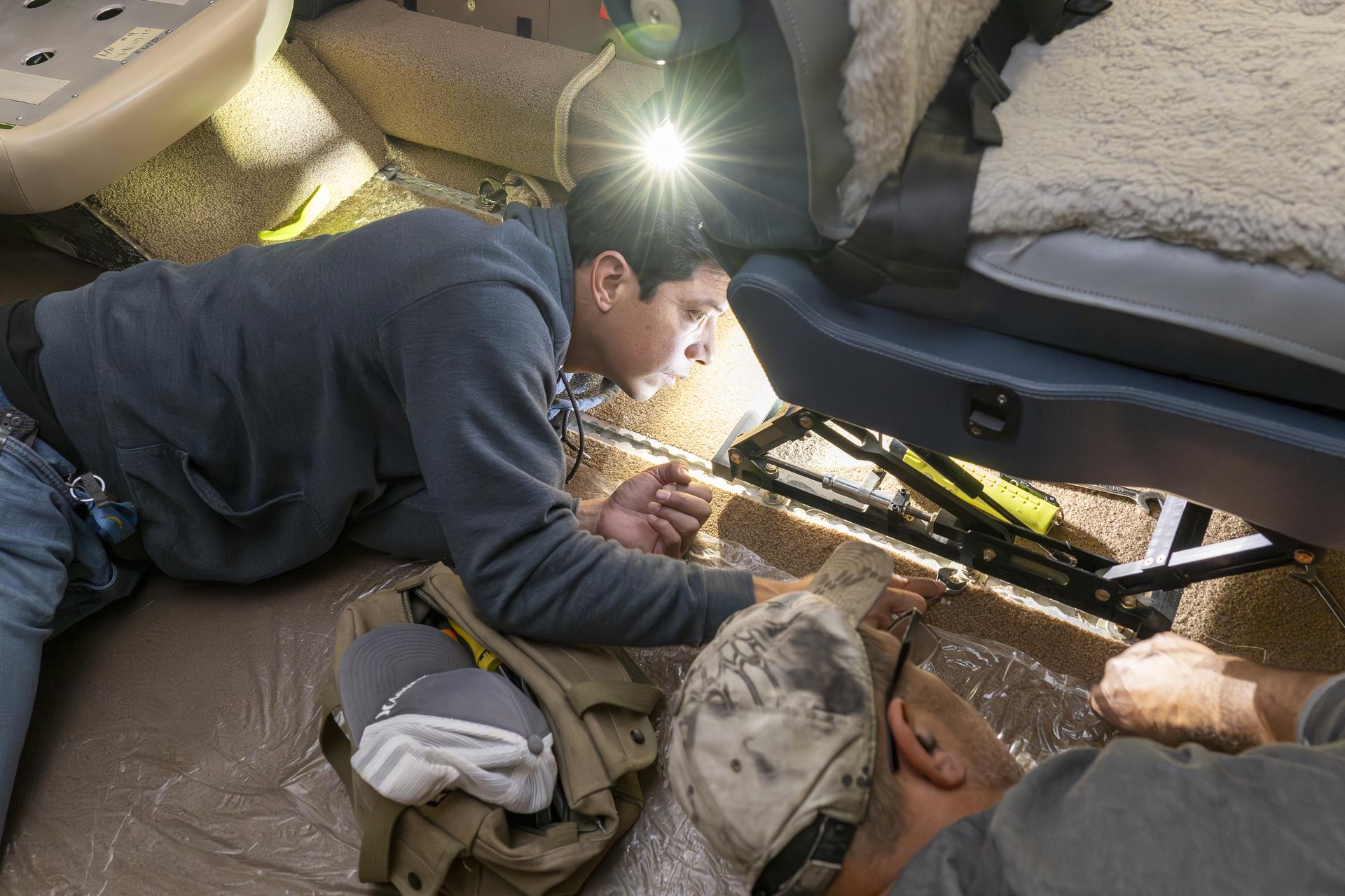
Manny Rodriguez, Gulfstream G-III aircraft crew chief, left, and Eric Apikian, aircraft mechanic, attach an instrumented seat onto a G-III on Wednesday, Jan. 7, 2026, at NASA’s Armstrong Flight Research Center in Edwards, California. The modifications prepare the aircraft to join three others flying at different altitudes to capture a complete view of the Orion spacecraft’s heat shield during Artemis II reentry. This effort is part of NASA’s Scientifically Calibrated In-Flight Imagery project.
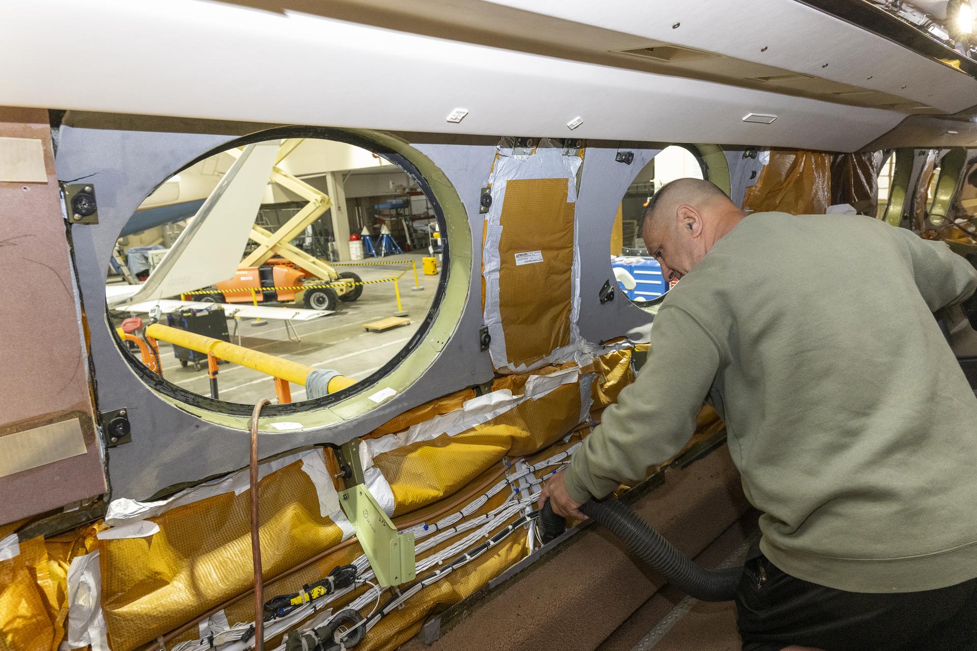
Eric Apikian, an aircraft mechanic, vacuums a NASA Gulfstream G-III aircraft compartment after wiring was added for sensors on Wednesday, Jan. 7, 2026, at NASA’s Armstrong Flight Research Center in Edwards, California. The modifications prepare the aircraft to join three others flying at different altitudes to capture a complete view of the Orion spacecraft’s heat shield during Artemis II reentry. This effort is part of NASA’s Scientifically Calibrated In-Flight Imagery project.
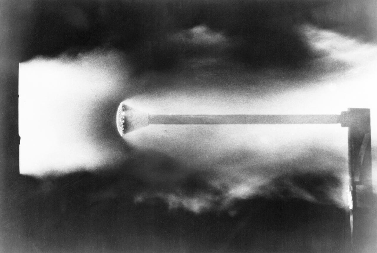
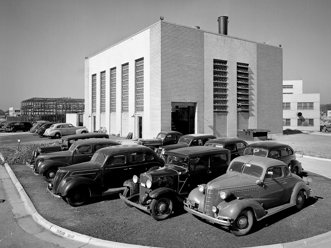
A hot jet research facility, used extensively in the design and development of the reentry heat shield on the Project Mercury spacecraft. The electrically-heated arc jet simulates the friction heating encountered by a space vehicle as it returns to the earth's atmosphere at high velocities. The arc jet was located in Langley's Structures Research Laboratory. It was capable of heating the air stream to about 9,000 degrees F. -- Published in Taken from an October 5, 1961 press release entitled: Hot Jet Research Facility used in Reentry Studies will be demonstrated at NASA Open House, October 7.

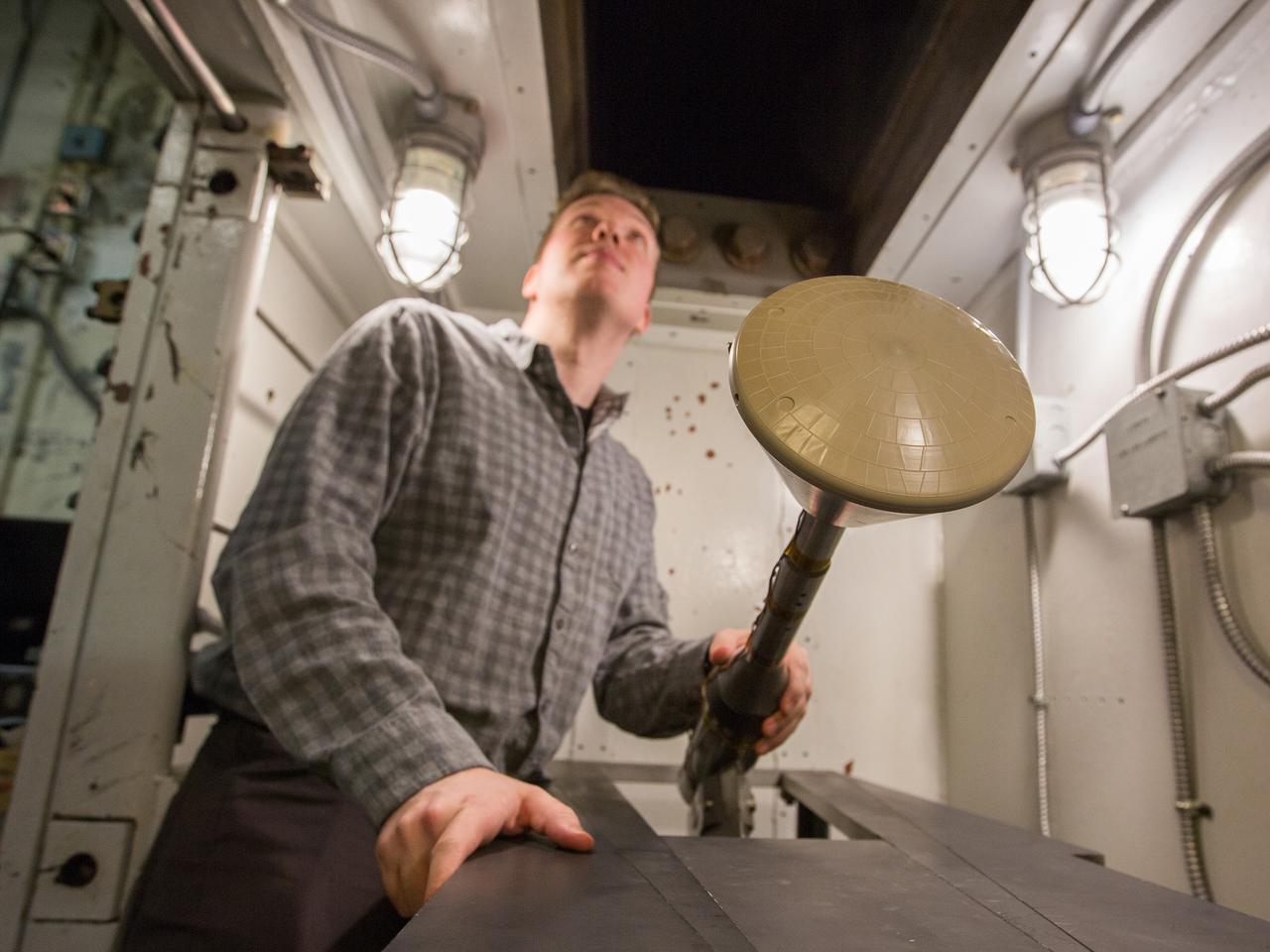
Peregrine, Radial Core Heat Spreader; Thermal Energy Conversion Research Hardware
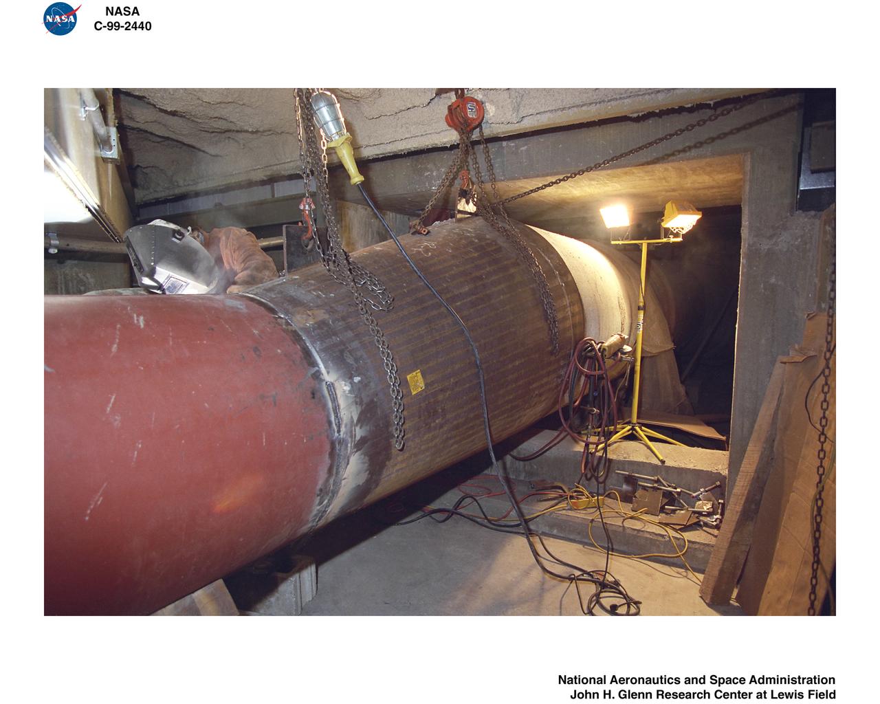
1999 CONSTRUCTION OF FACILITY ICING RESEARCH TUNNEL IRT HEAT EXCHANGER REPLACEMENT
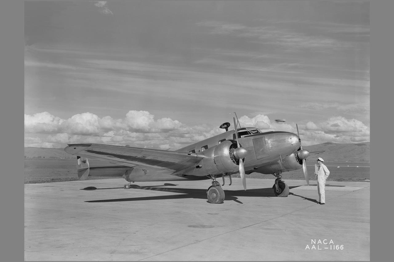
NACA photographer Lockheed 12A icing research airplane: with heated wings
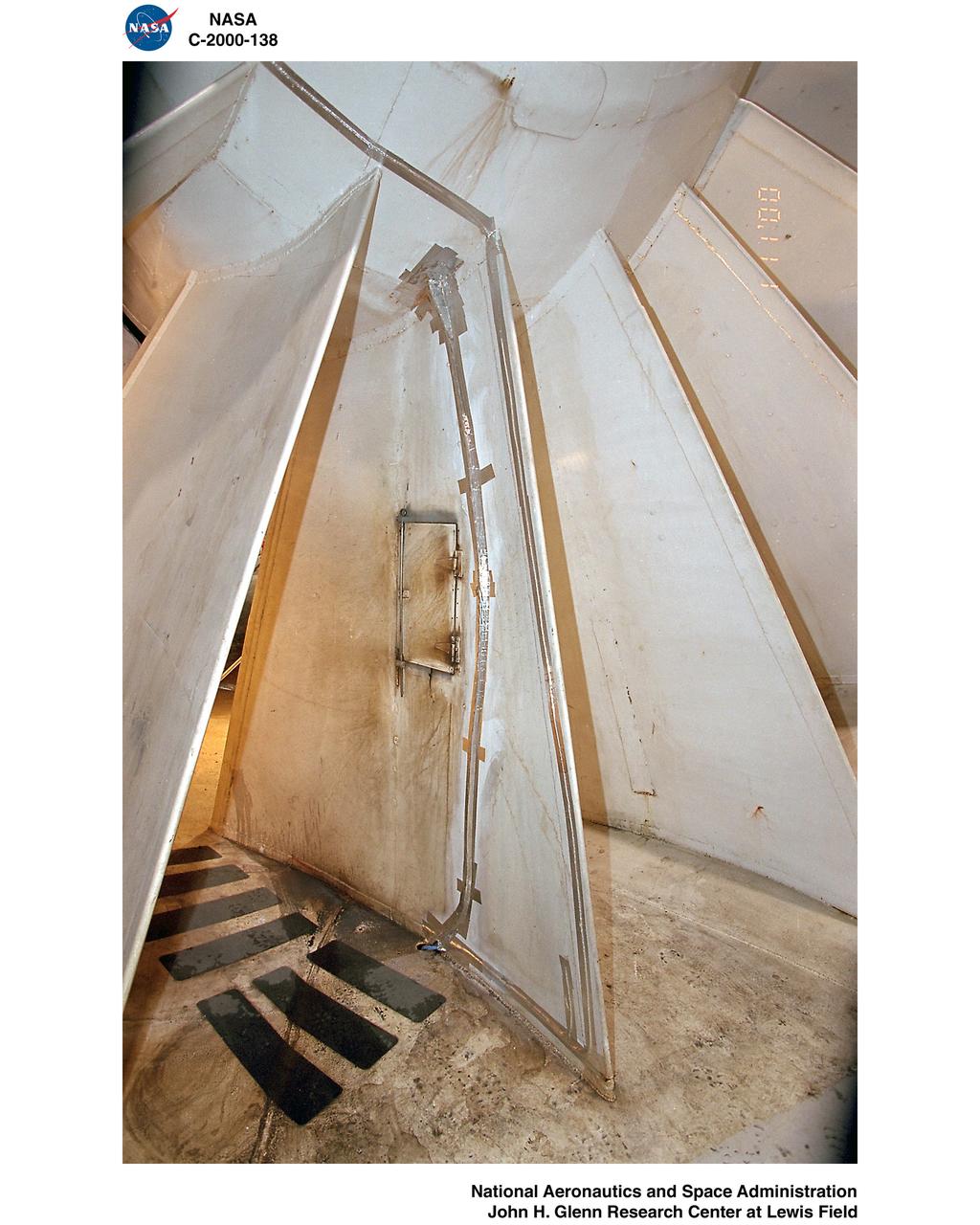
1999 CONSTRUCTION OF FACILITY ICING RESEARCH TUNNEL IRT HEAT EXCHANGER REPLACEMENT
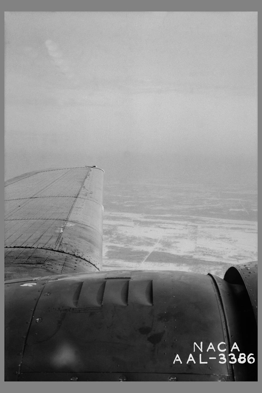
Minneapolis Ice research project: Ice formation on left wing of the Lockheed 12-A during flight after shutting off heat. The wind was completely cleared within 2 minutes after the application of heat.
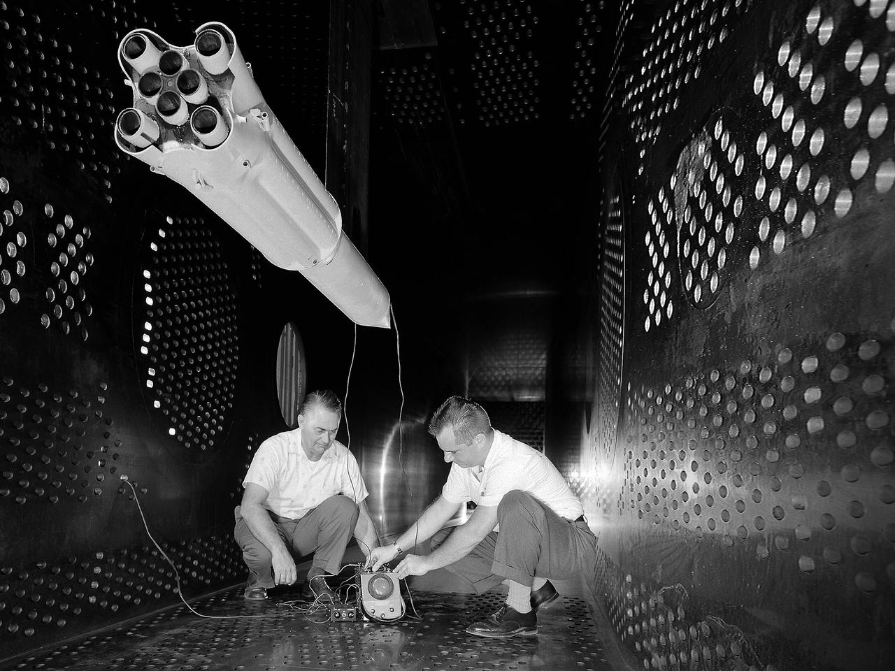
National Aeronautics and Space Administration (NASA) researchers set up instrumentation on a 0.037- scale model of a Saturn booster in the 8- by 6-Foot Supersonic Wind Tunnel at the NASA Lewis Research Center. In October 1960 Lewis researchers John Allen and Robert Wasko began a 14-month investigation of the eight-engine booster’s base heating in the tunnel. The model resembled the Saturn C-1, but only the afterbody totally mimicked the C-1. The over-heating of the lower end, or base, of the booster can cause the engines to fail or introduce aerodynamic concerns. Base heating results from the rocket engines’ exhaust heat, the recirculation of that heat into the base, and the burning of combustibles. Large boosters, like the Saturn, employed clusters of rocket engines that add to the complexity of the base heating problem. The 8- by 6-foot tunnel investigations studied the Saturn at speeds from Mach 1.0 to 2.0 using liquid oxygen and JP-4 as propellants. Researchers found that the use of cooling air scoops and external flow deflectors produced significant decreases in base heating.
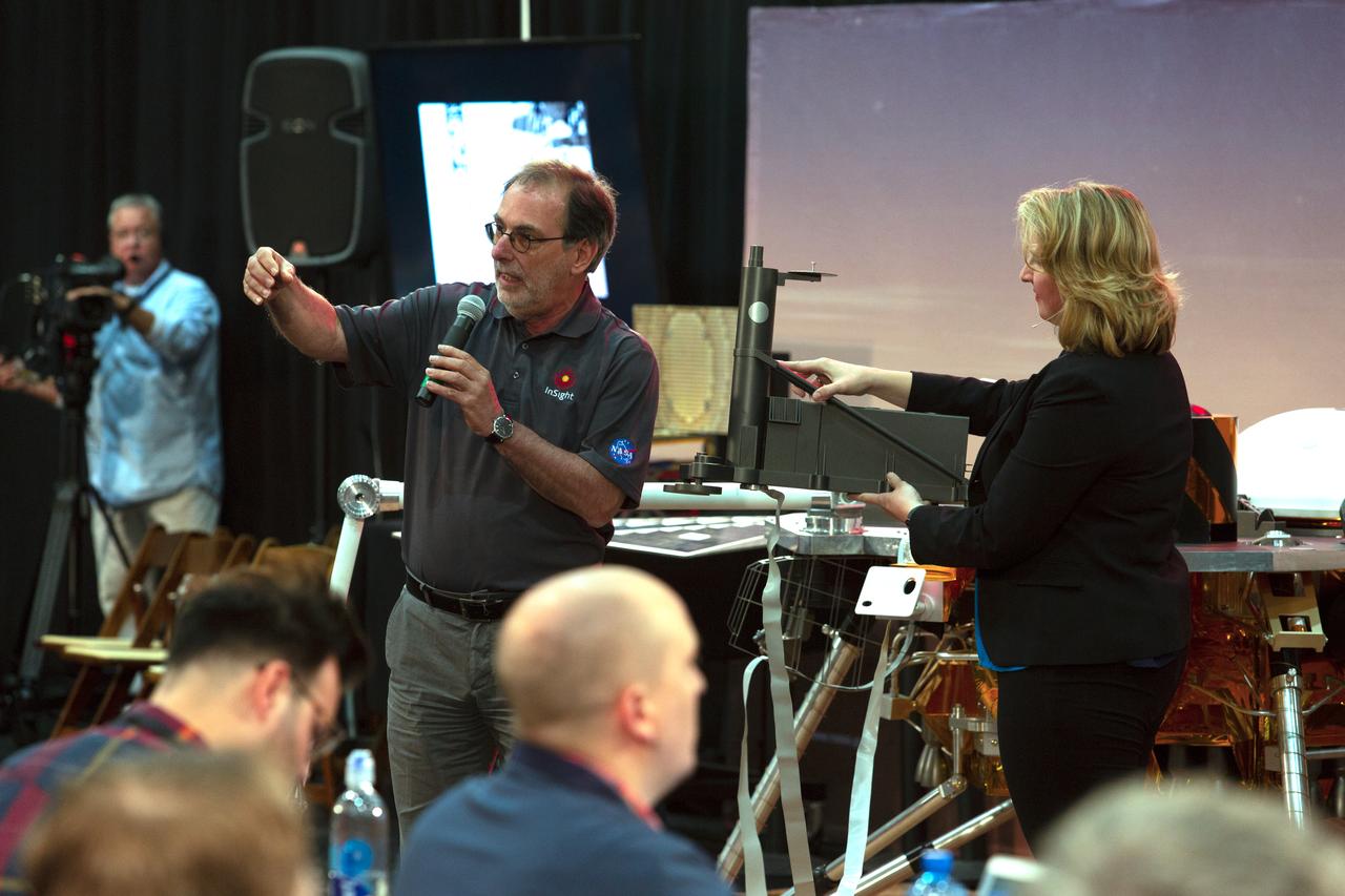
During a prelaunch briefing at Vandenberg Air Force Base in California, Tilman Spohn, HP3 Investigation Lead with the Institute of Planetary Research at the German Aerospace Center, speaks to members of the media. The presentation focused on NASA's Interior Exploration using Seismic Investigations, Geodesy and Heat Transport, or InSight, Mars lander. InSight is scheduled for liftoff May 5, 2018, atop a United Launch Alliance (ULA) Atlas V rocket from Space Launch Complex 3 at Vandenberg. The spacecraft will be the first mission to look deep beneath the Martian surface studying the planet's interior by measuring its heat output and listen for marsquakes.
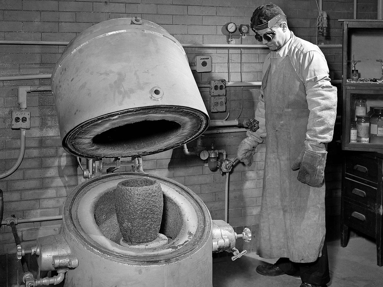
A technician prepares a metal component for a high-temperature bake in the Heat Treatment Shop at the National Advisory Committee for Aeronautics (NACA) Lewis Flight Propulsion Laboratory. Fabrication Division under Dan White and John Dalgleish created almost all of the equipment and models used at the laboratory. The Technical Services Building, referred to as the Fab Shop, contained a number of specialized shops in the 1940s and 1950s. These included a Machine Shop, Sheet Metal Shop, Wood and Pattern Shop, Instrument Shop, Thermocouple Shop, Heat Treating Shop, Metallurgical Laboratory, and Fabrication Office. The Metallurgical Laboratory contained a control lab for the Heat Treating Shop and a service lab for the NACA Lewis research divisions. This metallurgical group performed tensile and impact tests on metals to determine their suitability for specific research or equipment. The Heat Treating Shop heated metal parts to optimize their physical properties and contained a Precision Castings Foundry to manufacture equipment made of heat resisting alloys.
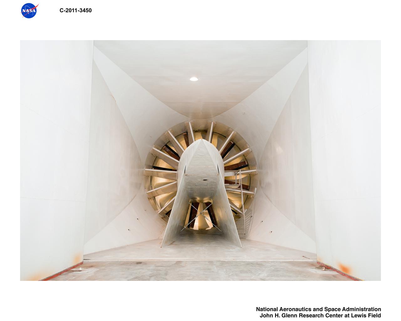
Construction of the Icing Research Tunnel, IRT, Refrigeration Plant-Newly Installed Heat Exchanger

NASA's Polar Radiant Energy in the Far-InfraRed Experiment (PREFIRE) mission will measure the amount of heat Earth emits into space from two of the coldest, most remote regions on the planet. Data from the mission will improve computer models researchers use to predict how Earth's ice, seas, and weather will change in a warming world. This artist's concept depicts one of two PREFIRE CubeSats in orbit around Earth. Earth absorbs a lot of the Sun's energy at the tropics, and weather and ocean currents transport that heat to the poles. Ice, snow, clouds, and other parts of the polar environment emit the heat into space, much of it in the form of far-infrared radiation. The difference between how much heat Earth absorbs at the tropics and then radiates out to space from the Arctic and Antarctic determines the planet's temperature and drives a dynamic system of climate and weather. But far-infrared emissions at the poles have never been systematically measured. This is where PREFIRE comes in. The mission will help researchers gain a clearer understanding of when and where Earth's poles emit far-infrared radiation, as well as how atmospheric water vapor and clouds influence the amount that escapes to space. PREFIRE is composed of two roughly shoebox-size CubeSats outfitted with specialized miniature heat sensors that will give researchers a more accurate picture of how much heat Earth emits into space. https://photojournal.jpl.nasa.gov/catalog/PIA26185
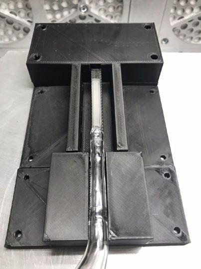
jsc2022e031220 (4/26/2022) --- A preflight image showing the Phase Change in Mixtures (PCIM) heat pipe module in its proposed housing. Microgravity Research for Versatile Investigations-Phase Change in Mixtures (MaRVIn-PCIM) examines the distribution of vapor and liquid within a wickless heat pipe. Image courtesy of Tec-Masters, Inc.
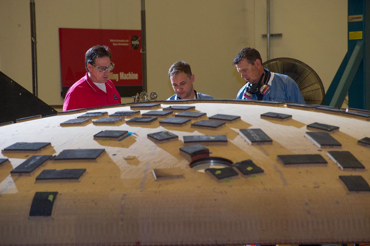
THE HEAT SHIELD ARRIVED MARCH 9 AT MARSHALL, WHERE EXPERTS FROM THE CENTER AND NASA’S AMES RESEARCH CENTER WILL EXTRACT SAMPLES OF THE ABLATIVE MATERIAL, OR AVCOAT
Shimmering heat waves trail behind NASA's Gulfstream-III research aircraft as it departs the Edwards AFB runway on a UAVSAR pod checkout test flight.
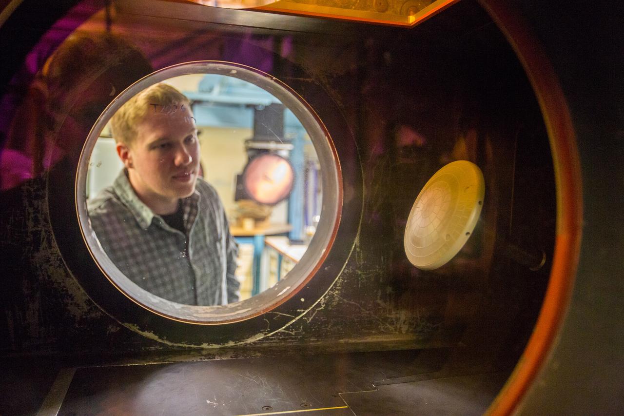
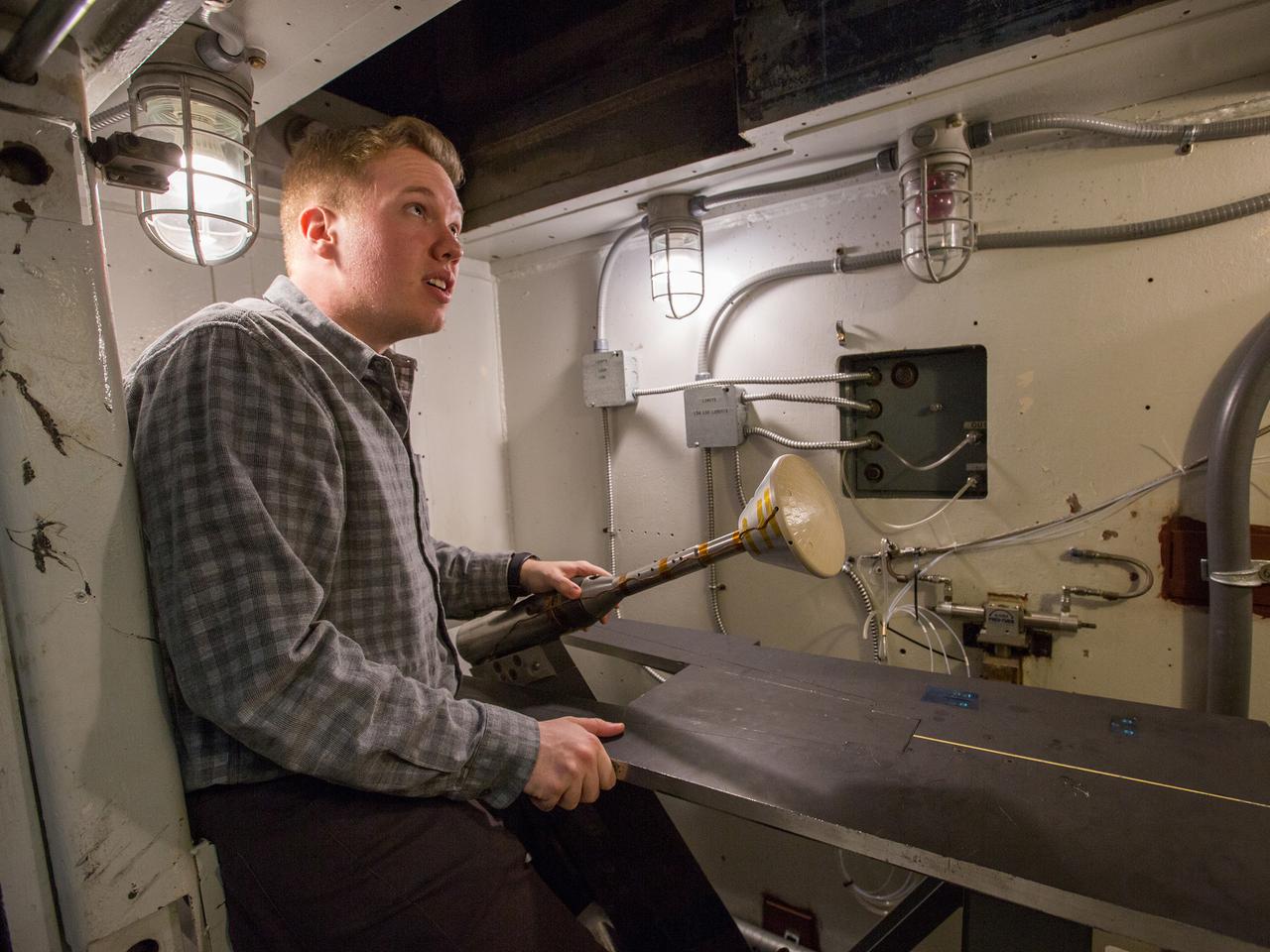
The Orion aerosciences team has performed more than 30 tests across the United States in support of the program, investigating the heating of the spacecraft during re-entry into Earth’s atmosphere. Testing recently concluded at NASA’s Langley Research Center in Hampton, Virginia with a 6-inch Orion heat shield model in the 20-inch Mach 6 wind tunnel, shown here on Feb. 4, 2019. The team includes engineers at Langley, NASA’s Johnson Space Center in Houston, Texas, and NASA’s Ames Research Center in Silicon Valley.
The Orion aerosciences team has performed more than 30 tests across the United States in support of the program, investigating the heating of the spacecraft during re-entry into Earth’s atmosphere. Testing recently concluded at NASA’s Langley Research Center in Hampton, Virginia with a 6-inch Orion heat shield model in the 20-inch Mach 6 wind tunnel, shown here on Feb. 4, 2019. The team includes engineers at Langley, NASA’s Johnson Space Center in Houston, Texas, and NASA’s Ames Research Center in Silicon Valley.
The Orion aerosciences team has performed more than 30 tests across the United States in support of the program, investigating the heating of the spacecraft during re-entry into Earth’s atmosphere. Testing recently concluded at NASA’s Langley Research Center in Hampton, Virginia with a 6-inch Orion heat shield model in the 20-inch Mach 6 wind tunnel, shown here on Feb. 4, 2019. The team includes engineers at Langley, NASA’s Johnson Space Center in Houston, Texas, and NASA’s Ames Research Center in Silicon Valley.
The Fuel Burner Rig is a test laboratory at NASA Glenn, which subjects new jet engine materials, treated with protective coatings, to the hostile, high temperature, high velocity environment found inside aircraft turbine engines. These samples face 200-mile per hour flames to simulate the temperatures of aircraft engines in flight. The rig can also simulate aircraft carrier and dusty desert operations where salt and sand can greatly reduce engine life and performance.
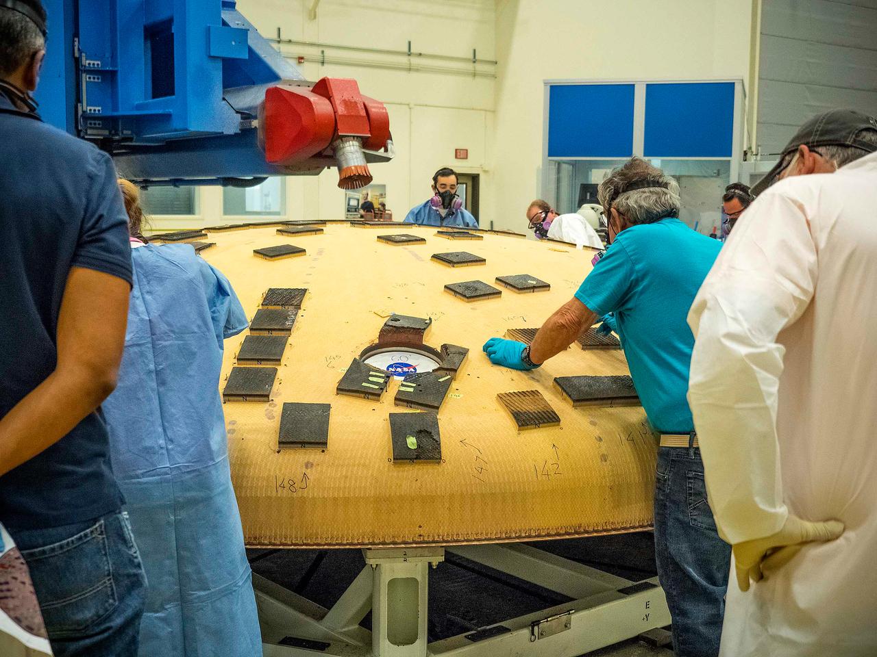
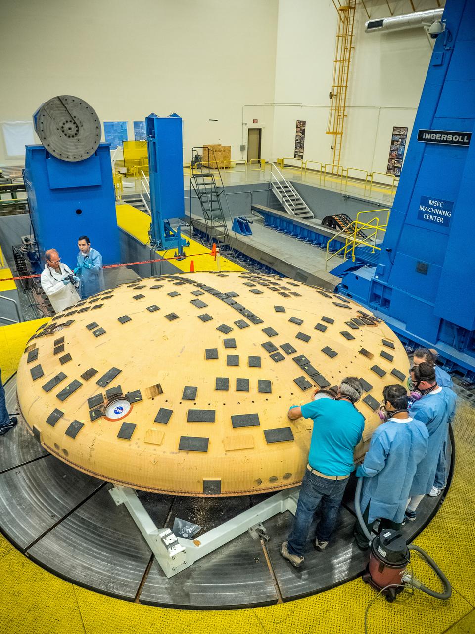
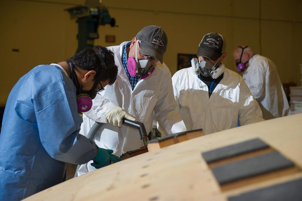
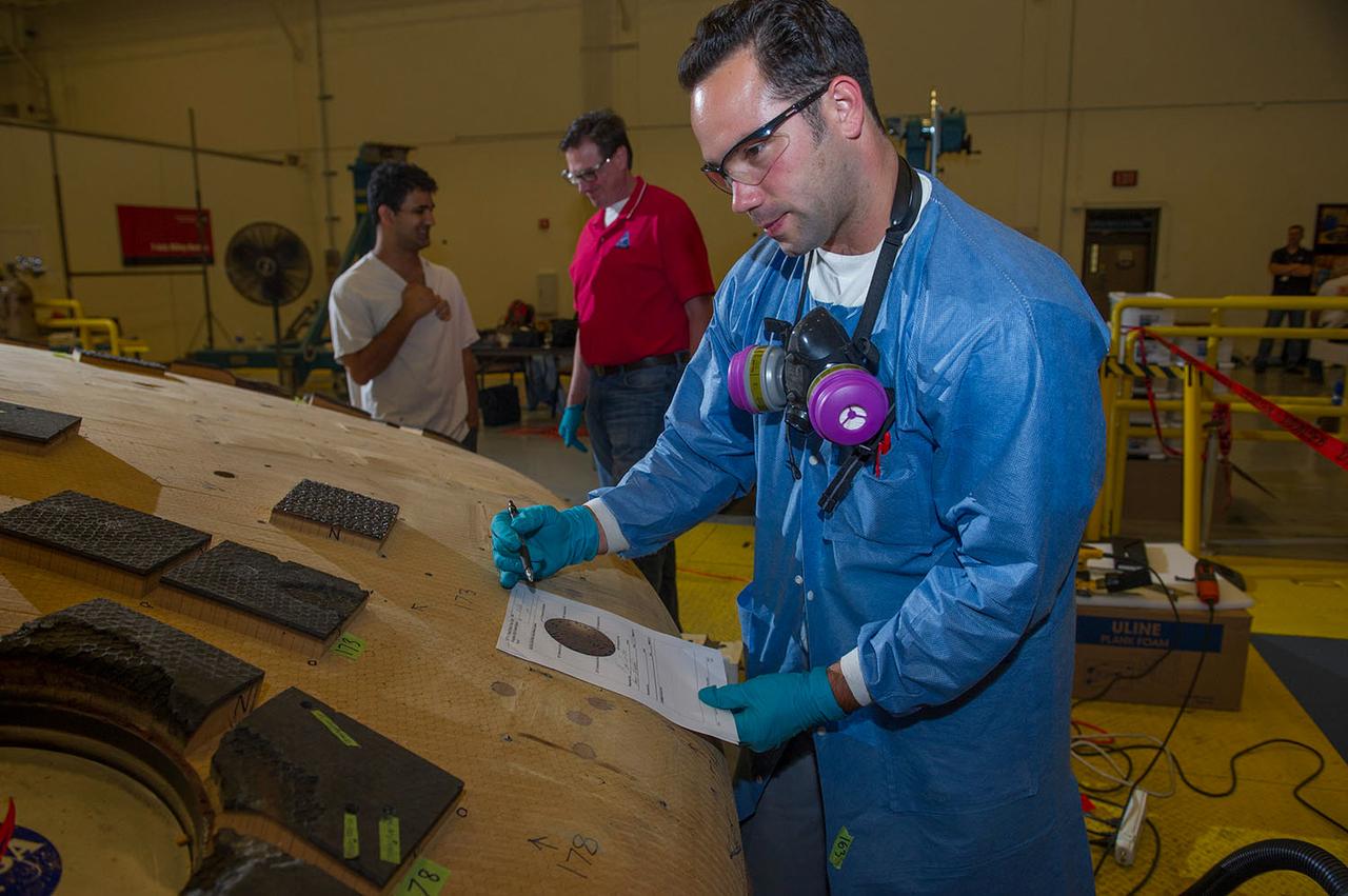
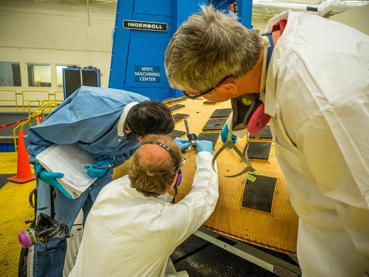
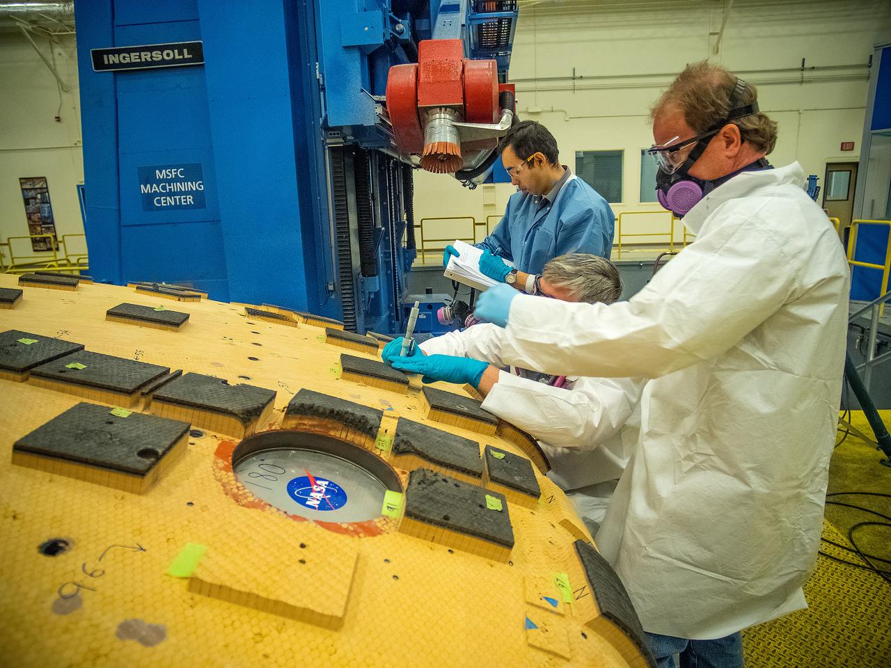
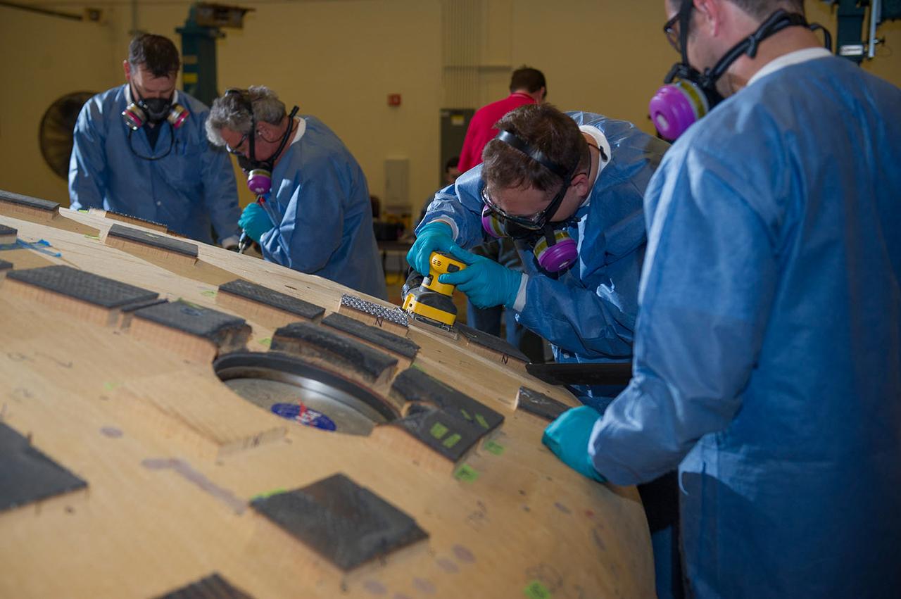
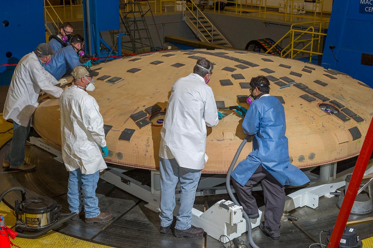
ENGINEERS FROM AMES RESEARCH CENTER AND MARSHALL SPACE FLIGHT CENTER REMOVE AVCOAT SEGMENTS FROM THE SURFACE OF THE ORION HEAT SHIELD, THE PROTECTIVE SHELL DESIGNED TO HELP THE NEXT GENERATION CREW MODULE WITHSTAND THE HEAT OF ATMOSPHERIC REENTRY. THE HEAT SHIELD FLEW TO SPACE DURING THE EFT-1 FULL SCALL FLIGHT TEST OF ORION IN DECEMBER 2014

A mechanic and apprentice work on a wooden impeller in the Fabrication Shop at the NACA Lewis Flight Propulsion Laboratory. The 260-person Fabrication Division created almost all of the equipment and models used at the laboratory. The Technical Services Building, referred to as the “Fab Shop”, contained a number of specialized shops in the 1940s and 1950s. These included a Machine Shop, Sheet Metal Shop, Wood and Pattern Shop, Instrument Shop, Thermocouple Shop, Heat Treating Shop, Metallurgical Laboratory, and Fabrication Office. The Machine Shop fabricated research equipment not commercially available. During World War II these technicians produced high-speed cameras for combustion research, impellers and other supercharger components, and key equipment for the lab’s first supersonic wind tunnel. The Wood and Pattern Shop created everything from control panels and cabinets to aircraft model molds for sheet metal work. The Sheet Metal Shop had the ability to work with 0.01 to 4-inches thick steel plates. The Instrument Shop specialized in miniature parts and instrumentation, while the Thermocouple Shop standardized the installation of pitot tubes and thermocouples. The Metallurgical Laboratory contained a control lab for the Heat Treating Shop and a service lab for the NACA Lewis research divisions. The Heat Treating Shop heated metal parts to optimize their physical properties and contained a Precision Castings Foundry to manufacture equipment made of heat resisting alloys.
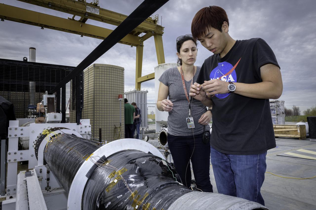
Ashley Karp, NASA JPL (Left) and Hunjoo Kim, NASA JPL (Right) attaching heat sensors the Peregrine Hybrid Rocket Engine prior to its test at the Outdoor Aerodynamic Research Facility (OARF, N-249) at NASA's Ames Research Center.
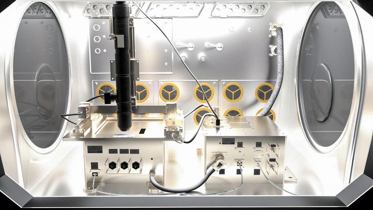
jsc2022e031219 (4/26/2022) A preflight image showing the Microgravity Research for Versatile Investigations-Phase Change in Mixtures.(MaRVIin PCIM) system as it would be housed in the microgravity glovebox facility on the ISS. The Microgravity Research for Versatile Investigations-Phase Change in Mixtures (MaRVIn-PCIM) examines the distribution of vapor and liquid within a wickless heat pipe.
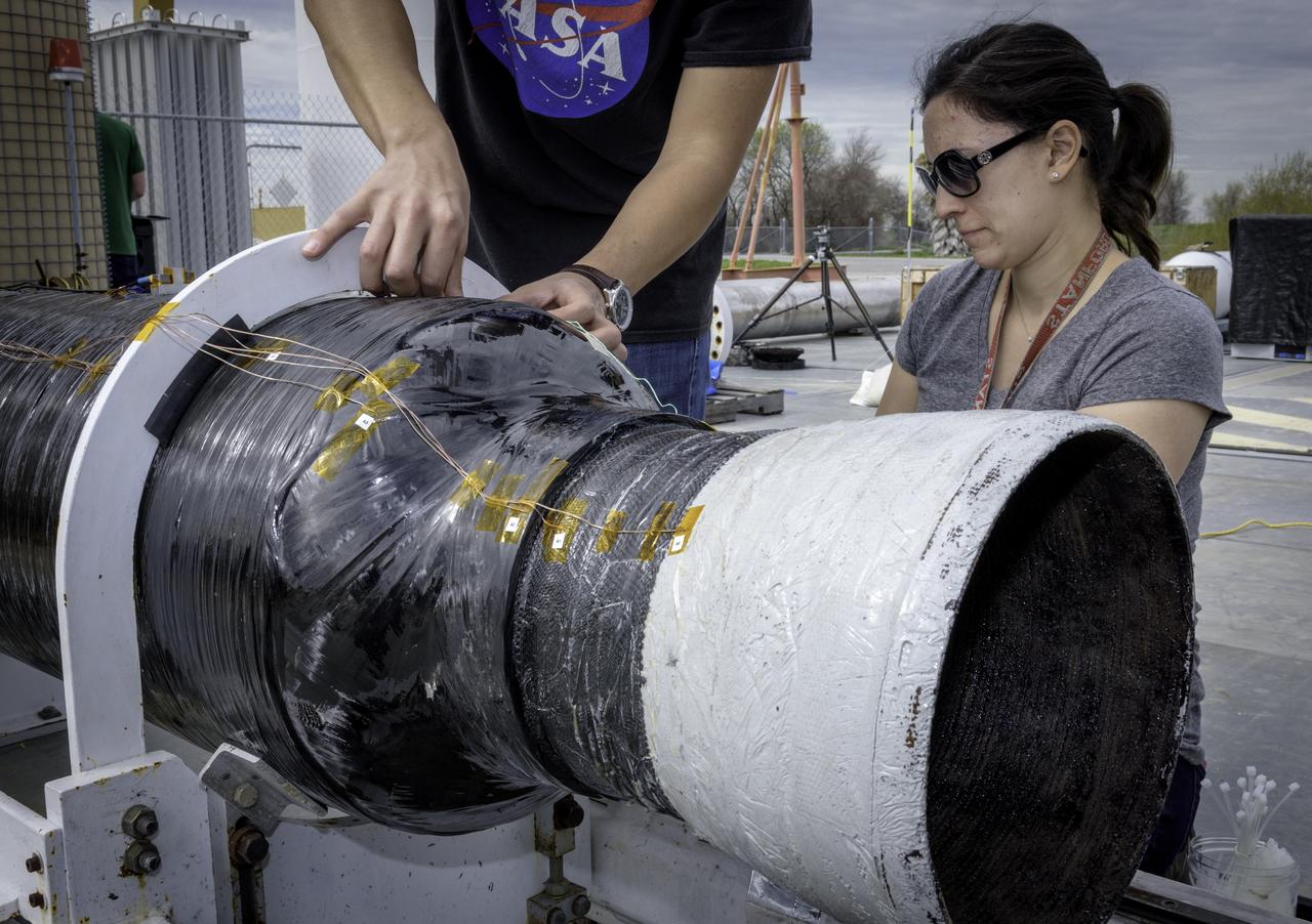
Hunjoo Kim, NASA JPL (Left) and Ashley Karp, NASA JPL (Right) attaching heat sensors the Peregrine Hybrid Rocket Engine prior to its test at the Outdoor Aerodynamic Research Facility (OARF, N-249) at NASA’s Ames Research Center.
A technician prepares a 2.25 percent scale model of the space shuttle for a base heat study in the 10- by 10-Foot Supersonic Wind Tunnel at the National Aeronautics and Space Administration (NASA) Lewis Research Center. This space shuttle project, begun here in July 1976, was aimed at evaluating base heating and pressure prior to the Shuttle’s first lift-off scheduled for 1979. The space shuttle was expected to experience multifaceted heating and pressure distributions during the first and second stages of its launch. Engineers needed to understand these issues in order to design proper thermal protection. The test’s specific objectives were to measure the heat transfer and pressure distributions around the orbiter’s external tank and solid rocket afterbody caused by rocket exhaust recirculation and impingement, to measure the heat transfer and pressure distributions caused by rocket exhaust-induced separation, and determine gas recovery temperatures using gas temperature probes and heated base components. The shuttle model’s main engines and solid rockets were first fired and then just the main engines to simulate a launch during the testing. Lewis researchers conducted 163 runs in the 10- by 10 during the test program.
Space Shuttle tile test in 60MW Interaction Heating Facility N-238 (used in NASA/AMES publication 'Searching the Horizon' - A History of Ames Research Center SP-4304)
Construction of the new NASA Ames Green Building dubbed Sustainability Base located on the Ames Research Center campus at Moffett Field, CA. Raised floors for heating from beneath.
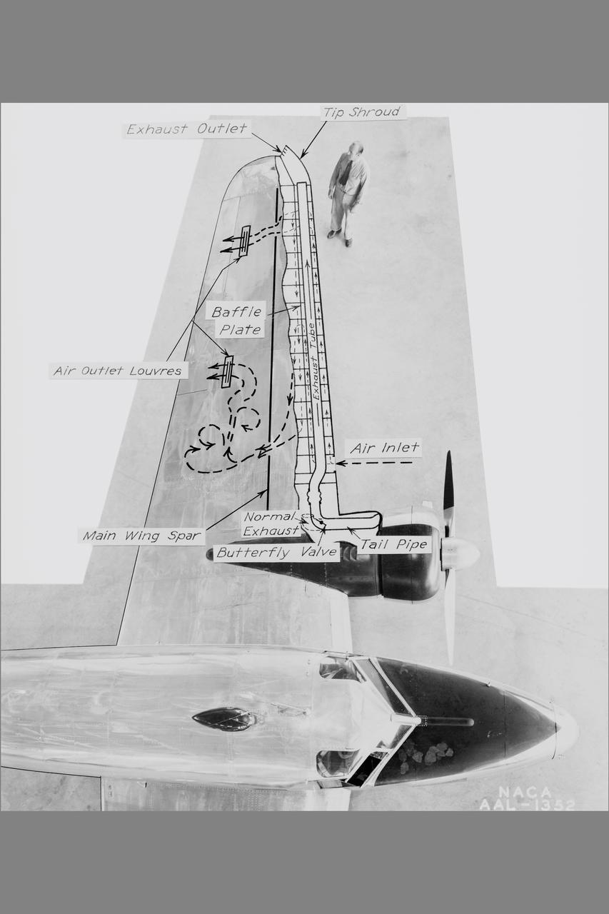
NACA Photographer NASA Ames De-icing project: diagram of the systems using exhaust-heated air to prevent icing on the Lockheed 12A wings Published: Adventures in Research SP-4302
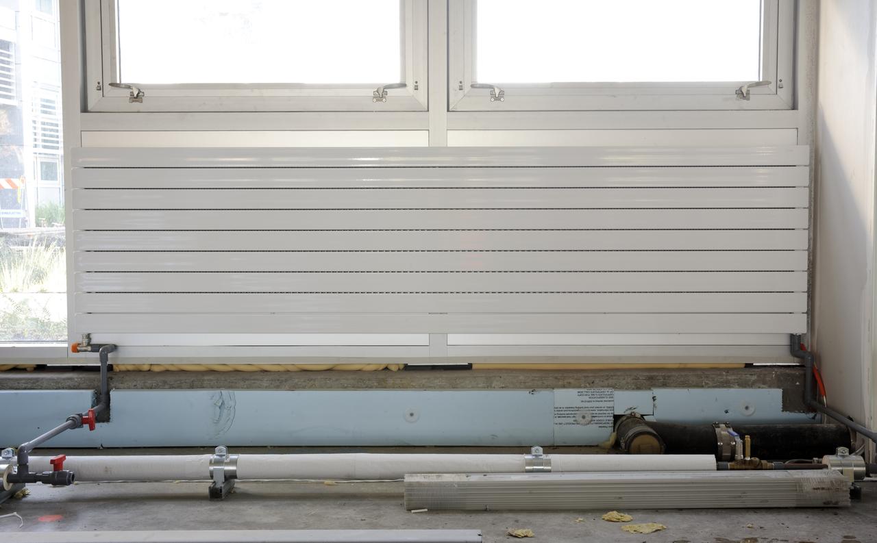
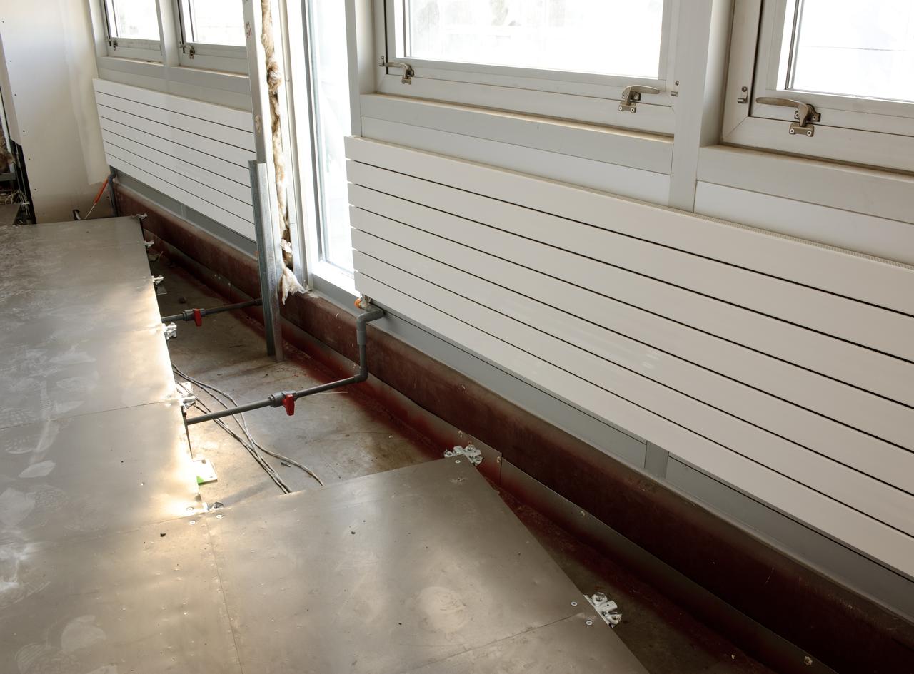
Construction of the new NASA Ames Green Building dubbed Sustainability Base located on the Ames Research Center campus at Moffett Field, CA. heating panels on walls under windows
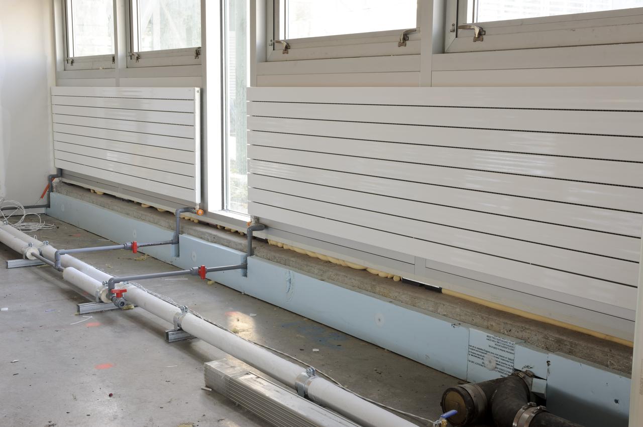
Construction of the new NASA Ames Green Building dubbed Sustainability Base located on the Ames Research Center campus at Moffett Field, CA. heating panels on walls under windows
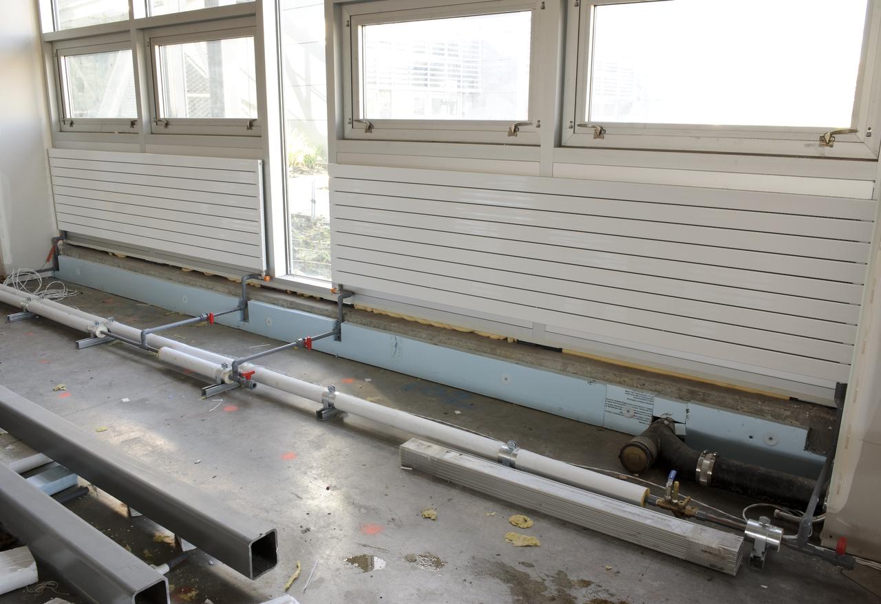
Construction of the new NASA Ames Green Building dubbed Sustainability Base located on the Ames Research Center campus at Moffett Field, CA. heating panels on walls under windows
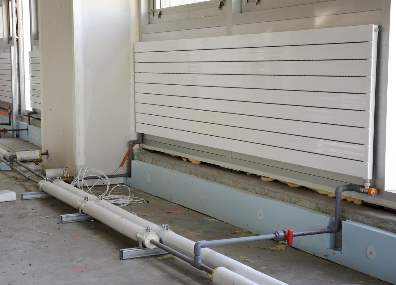
Construction of the new NASA Ames Green Building dubbed Sustainability Base located on the Ames Research Center campus at Moffett Field, CA. heating panels on walls under windows
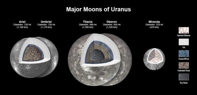
New modeling shows that there likely is an ocean layer in four of Uranus' major moons: Ariel, Umbriel, Titania, and Oberon. Salty – or briny – oceans lie under the ice and atop layers of water-rich rock and dry rock. Miranda is too small to retain enough heat for an ocean layer. The modeling, detailed in a paper published in the Journal of Geophysical Research, was informed by a re-analysis of data from NASA's Voyager spacecraft. Scientists have long thought that Titania, given its size, would be most likely to retain internal heat, caused by radioactive decay. The other moons had been widely considered too small to retain the heat necessary to keep an internal ocean from freezing, especially as heating created by the gravitational pull of Uranus is only a minor source of heat. https://photojournal.jpl.nasa.gov/catalog/PIA25500
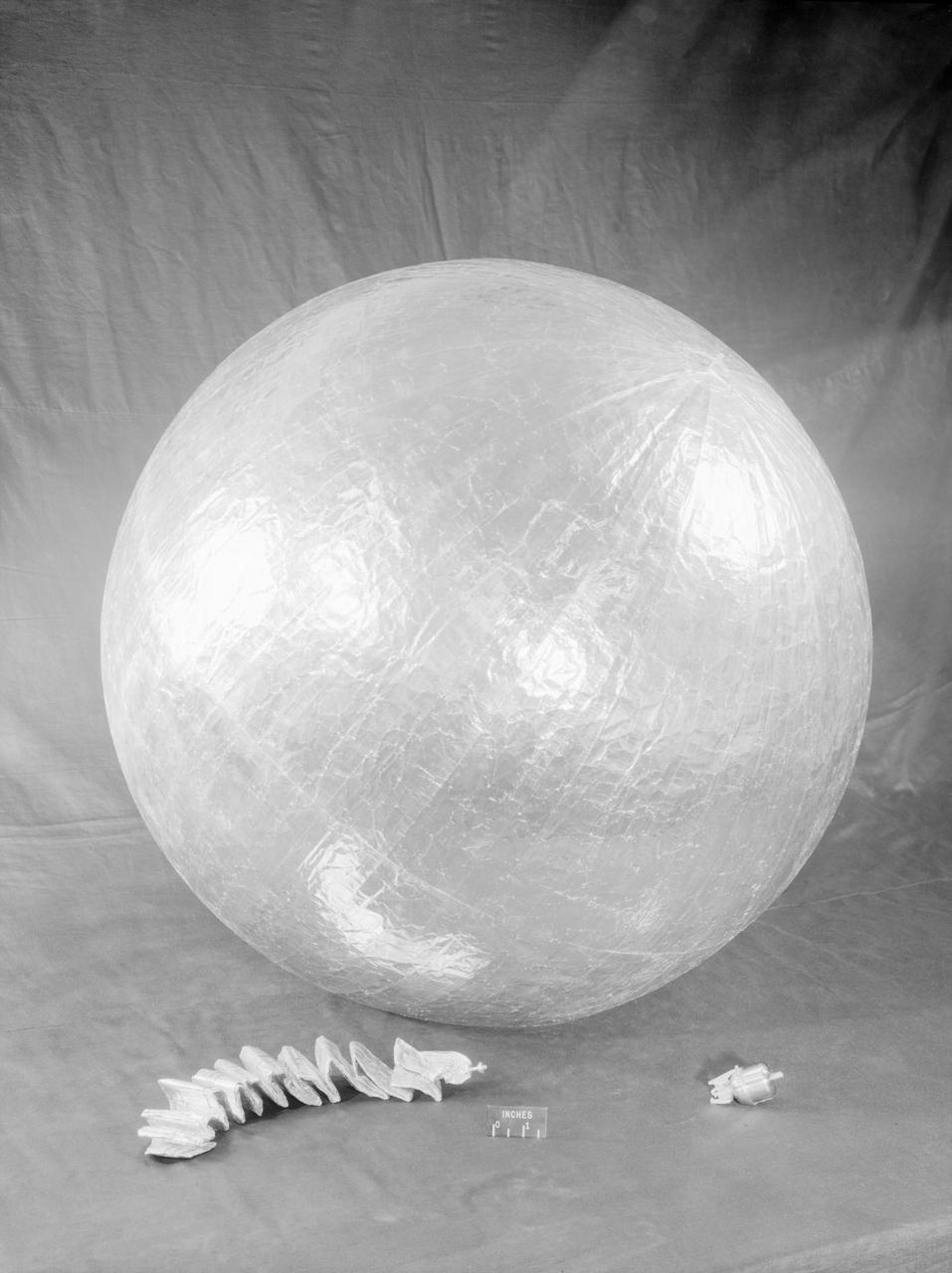
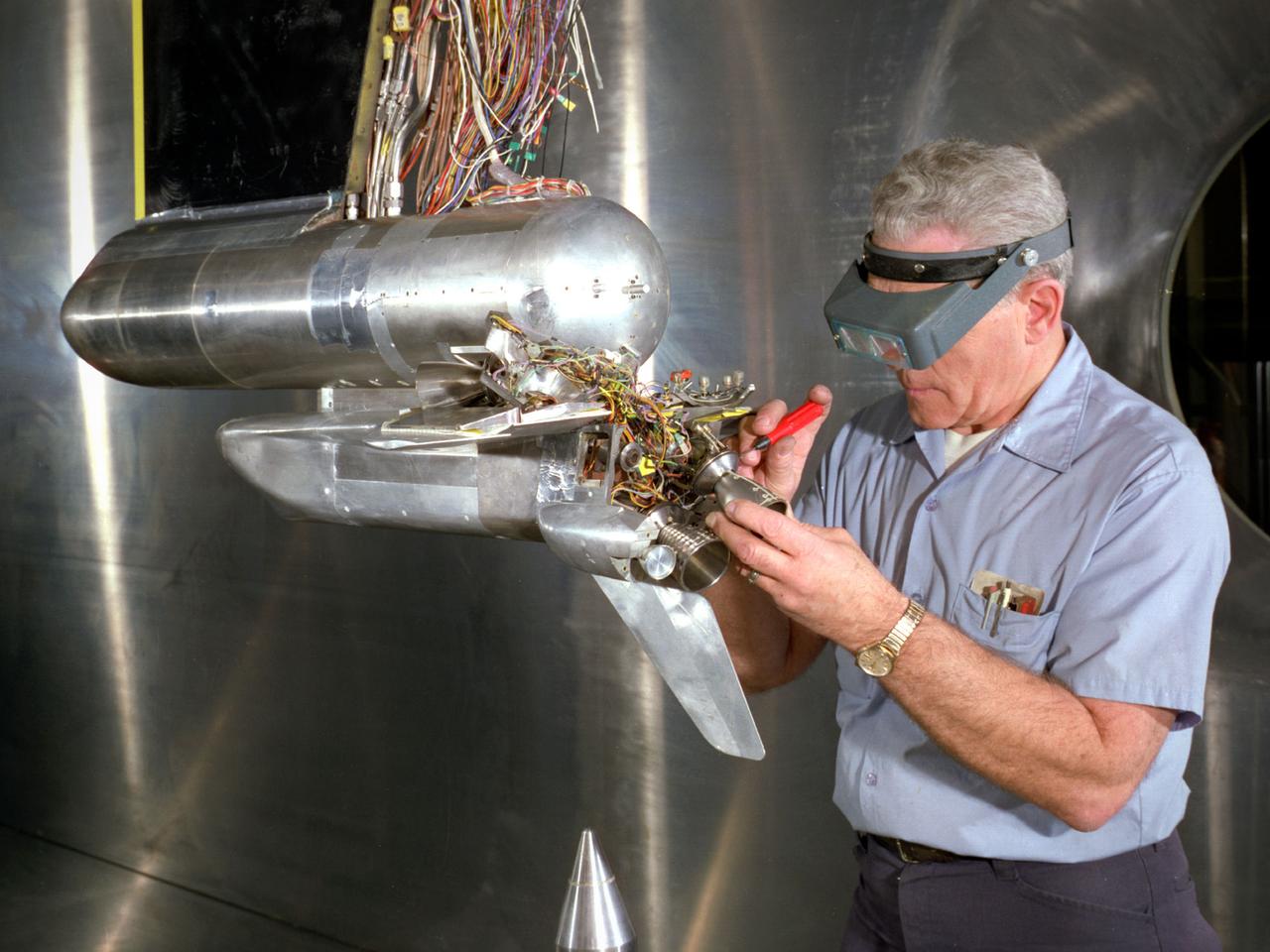
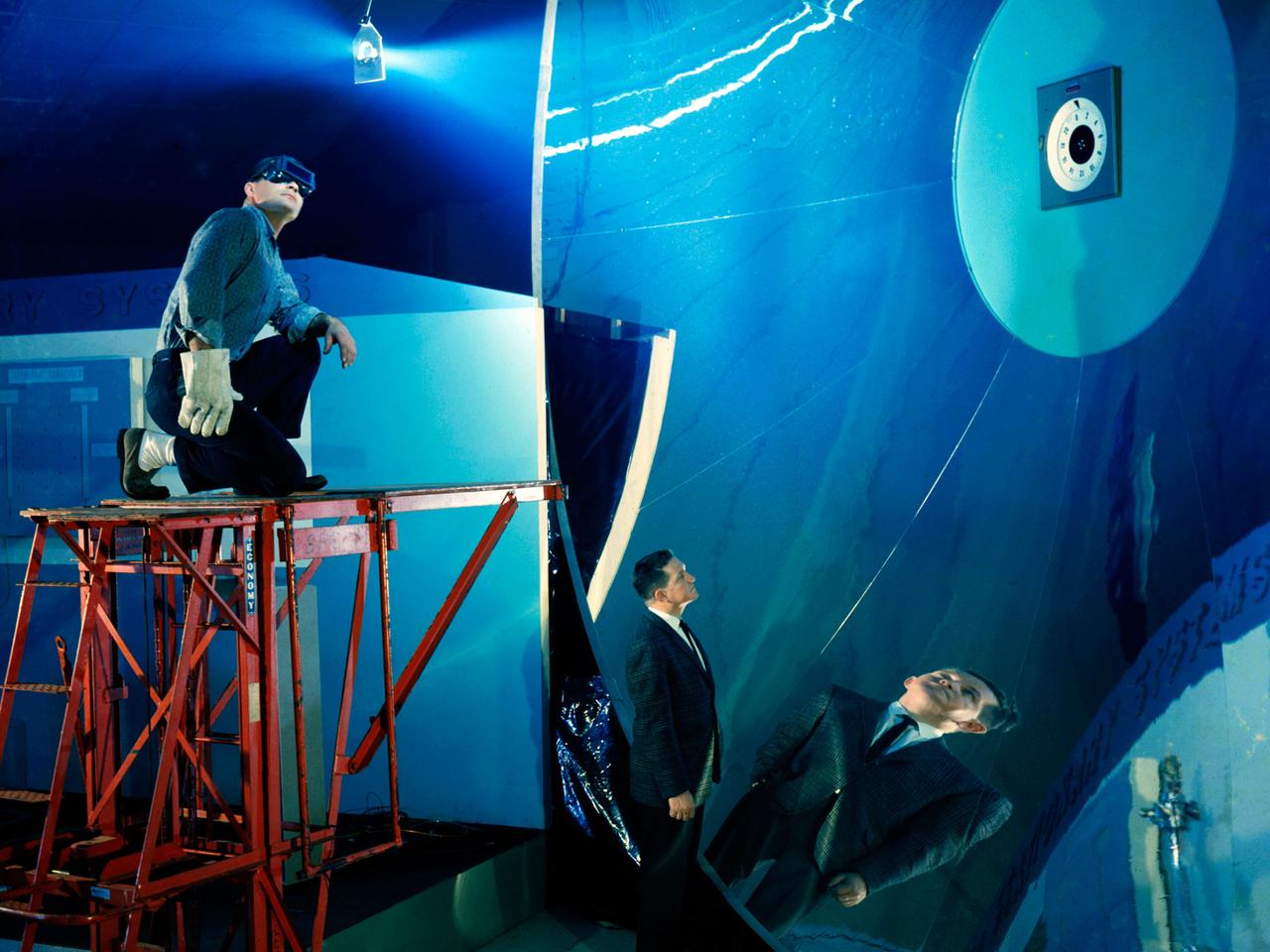
James Hansen describes the work on Project Echo s air density experiment known as the Sub-Satellite. Before launch engineers subjected the sub-satellite to many tests. Here, the sub-satellite is shown prior to tests to determine the capacity of the 30-inch Sub-Satellite to withstand the high temperature of direct sunlight in space, Langley researchers subjected it to 450 F heat test. Results indicated that the aluminum-covered Mylar plastic would effectively reflect the dangerous heat. -- Published in James R. Hansen, Spaceflight Revolution: NASA Langley Research Center From Sputnik to Apollo, NASA SP-4308, p. 168.
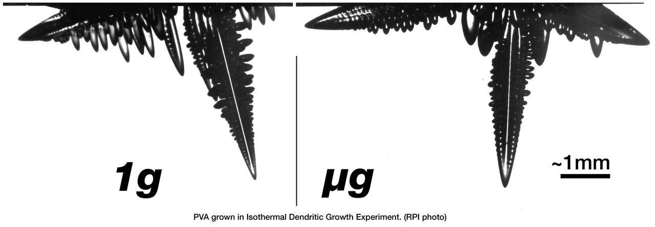
The Isothermal Dendritic Growth Experiment (IDGE), flown on three Space Shuttle missions, is yielding new insights into virtually all industrially relevant metal and alloy forming operations. IDGE used transparent organic liquids that form dendrites (treelike structures) similar to those inside metal alloys. Comparing Earth-based and space-based dendrite growth velocity, tip size and shape provides a better understanding of the fundamentals of dentritic growth, including gravity's effects. Shalowgraphic images of pivalic acid (PVA) dendrites forming from the melt show the subtle but distinct effects of gravity-driven heat convection on dentritic growth. In orbit, the dendrite grows as its latent heat is liberated by heat conduction. This yields a blunt dendrite tip. On Earth, heat is carried away by both conduction and gravity-driven convection. This yields a sharper dendrite tip. In addition, under terrestrial conditions, the sidebranches growing in the direction of gravity are augmented as gravity helps carry heat out of the way of the growing sidebranches as opposed to microgravity conditions where no augmentation takes place. IDGE was developed by Rensselaer Polytechnic Institute and NASA/Glenn Research Center. Advanced follow-on experiments are being developed for flight on the International Space Station. Photo Credit: NASA/Glenn Research Center
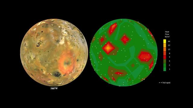
This frame from an animation shows Jupiter volcanic moon Io as seen by NASA Voyager and Galileo spacecraft (at left) and the pattern of heat flow from 242 active volcanoes (at right). The red and yellow areas are places where local heat flow is greatest -- the result of magma erupting from Io's molten interior onto the surface. The map is the result of analyzing decades of observations from spacecraft and ground-based telescopes. It shows Io's usual volcanic thermal emission, excluding the occasional massive but transient "outburst" eruption; in other words, this is what Io looks like most of the time. This heat flow map will be used to test models of interior heating. The map shows that areas of enhanced volcanic heat flow are not necessarily correlated with the number of volcanoes in a particular region and are poorly correlated with expected patterns of heat flow from current models of tidal heating -- something that is yet to be explained. This research is published in association with a 2015 paper in the journal Icarus by A. Davies et al., titled "Map of Io's Volcanic Heat Flow," (http://dx.doi.org/10.1016/j.icarus.2015.08.003.) http://photojournal.jpl.nasa.gov/catalog/PIA19655
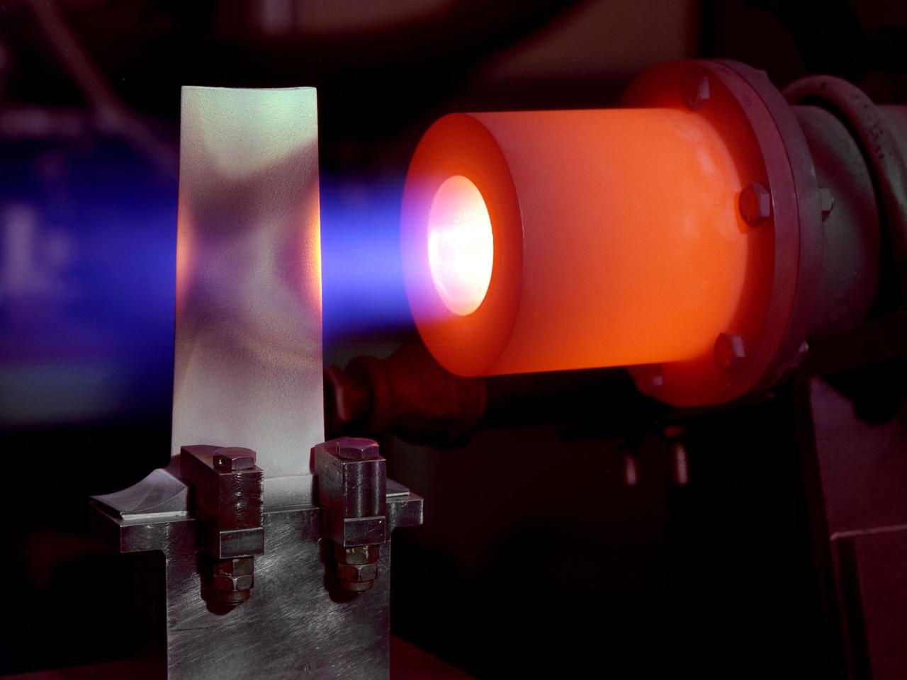
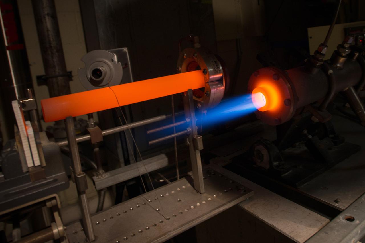
A 1-foot long stator blade with a thermal coating subjected to intense heat in order to test its strength at the National Aeronautics and Space Administration (NASA) Lewis Research Center. Lewis researchers sought to determine optimal types of ceramic coatings to increase the durability of metals. The research was primarily intended to support the design of stator blades for high-performance axial-flow compressor and turbofan engines. The coatings reduced the temperature of the metal and the amount of required cooling. As engines became more and more sophisticated, compressor blades were required to withstand higher and higher temperatures. Lewis researchers developed a dual-layer thermal-barrier coating that could be applied to turbine vanes and blades and combustion liners. This new sprayable thermal-barrier coating was evaluated for its durability, strength, fatigue, and aerodynamic penalties. This hot-gas rig fired the scorching gas at the leading edge of a test blade. The blade was cooled by an internal air flow. The blades were heated at two different velocities during the program. When using Mach 0.3 gases the entire heating and cooling cycle only lasted 30 seconds. The cycle lasted 60 minutes during tests at Mach 1.
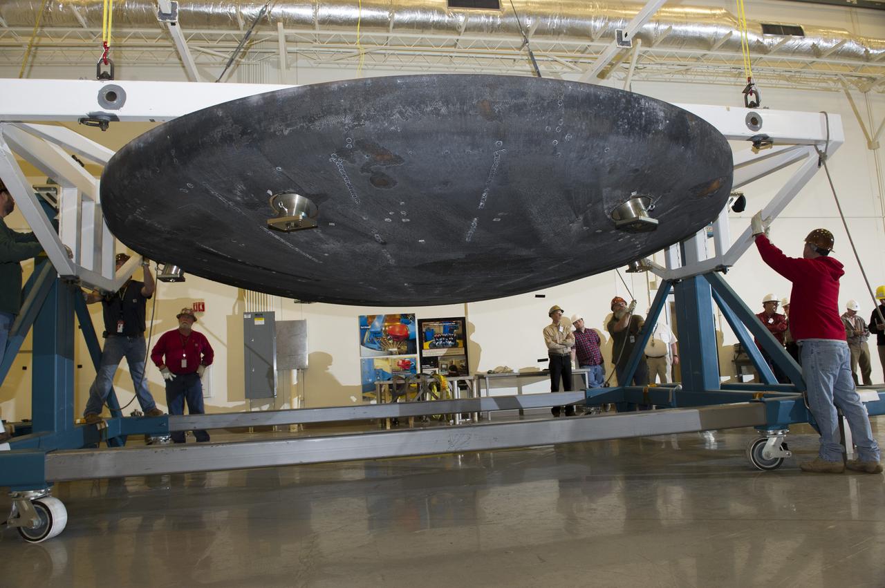
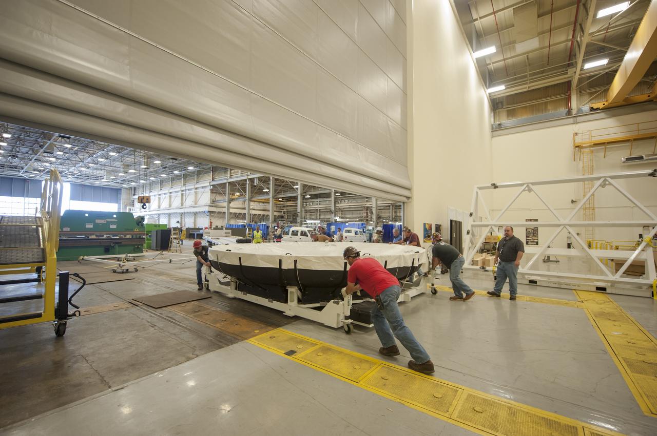
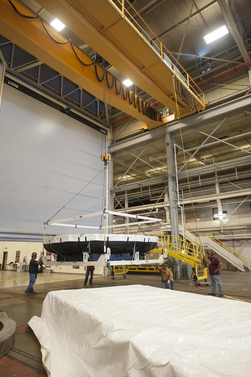
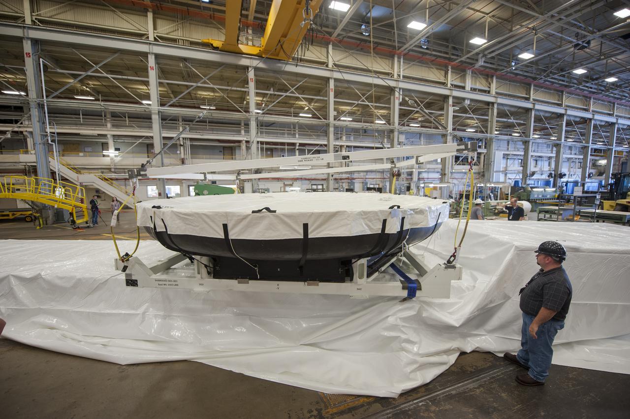
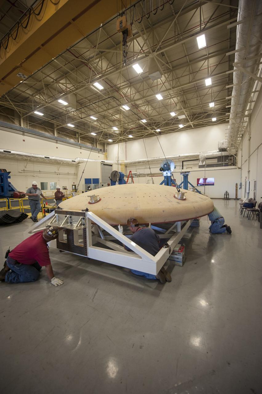
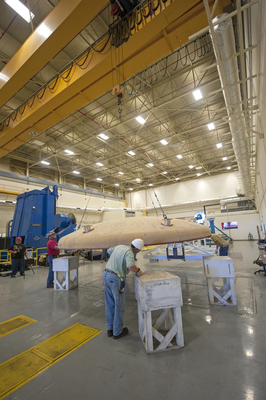
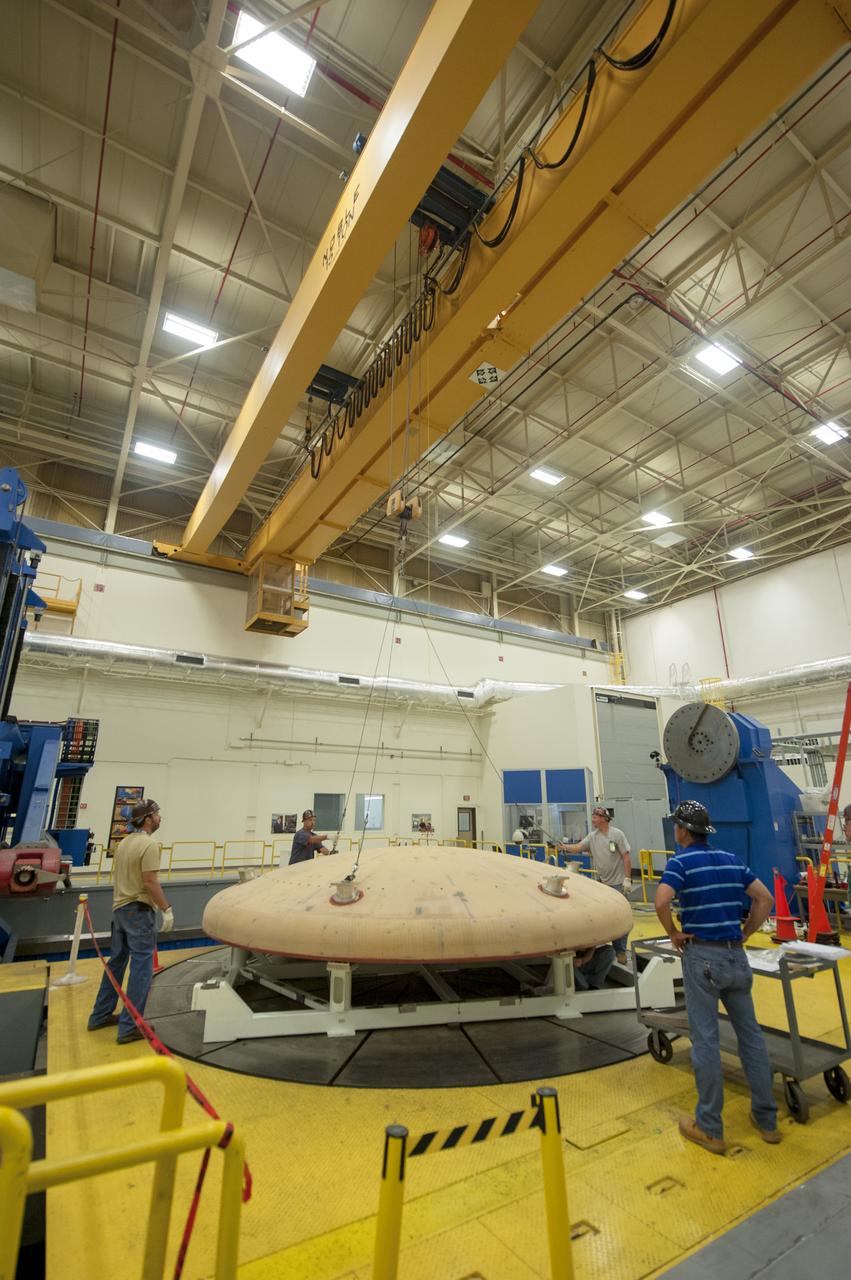
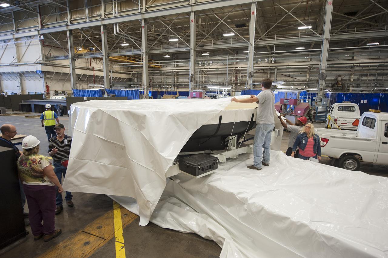
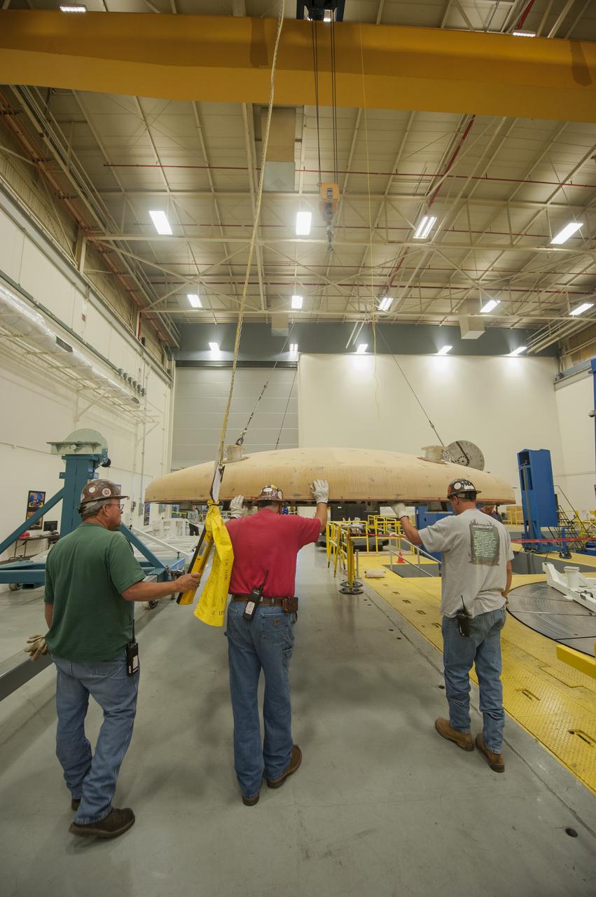
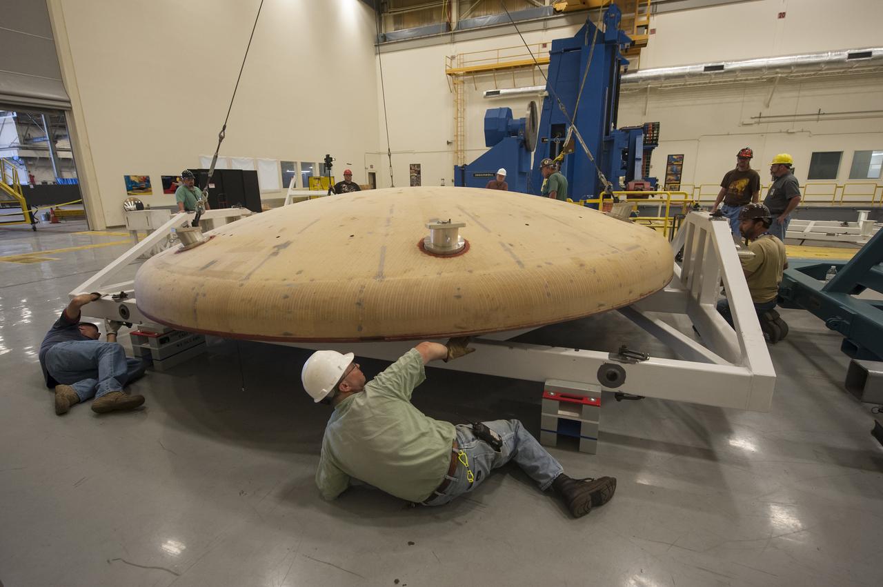
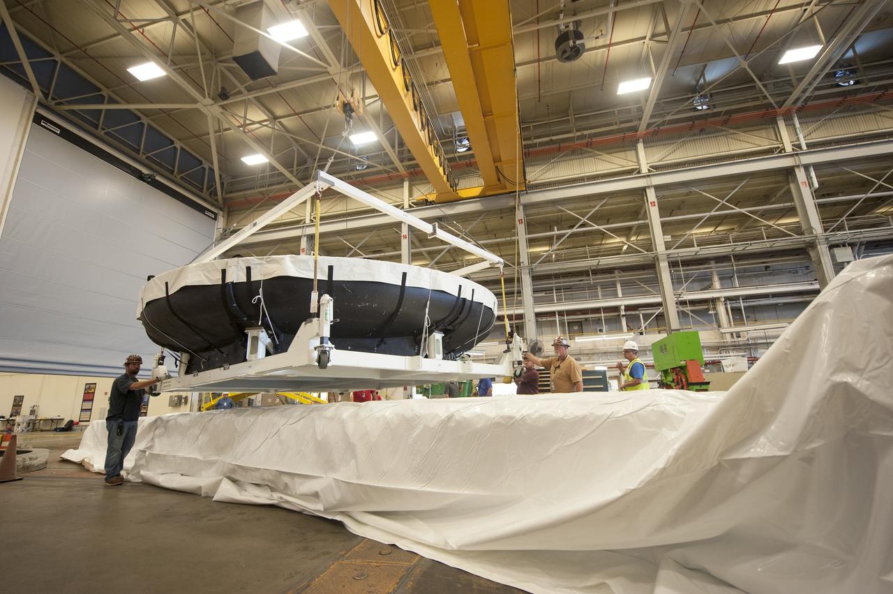
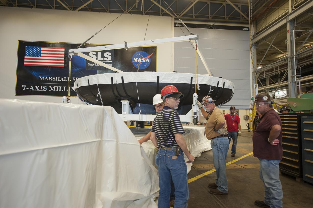
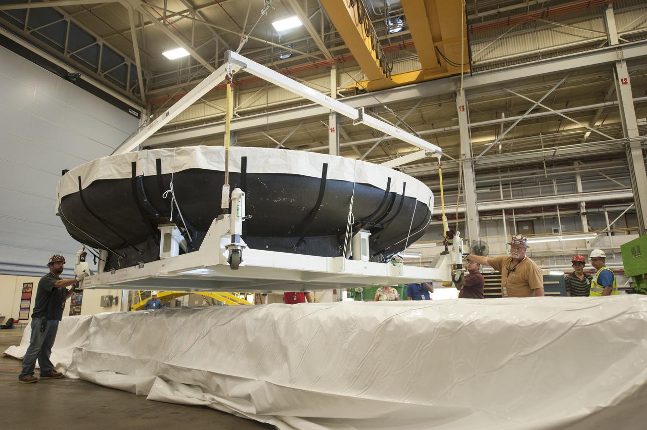
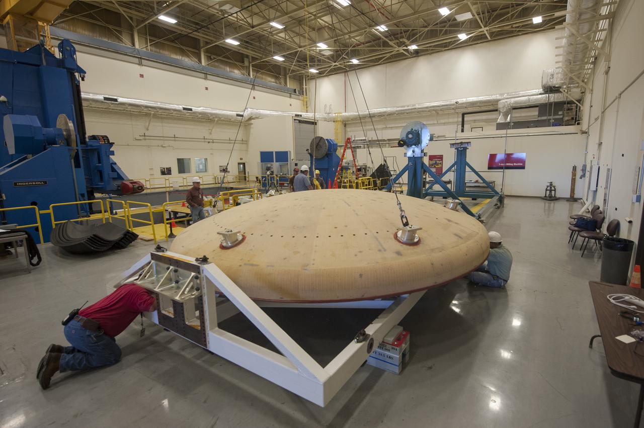
THE ORION HEAT SHIELD, WHICH WAS AT NASA’S MARSHALL SPACE FLIGHT CENTER FROM MARCH-MAY 2015 FOR ENGINEERING AND ANALYSIS, IS READIED FOR DEPARTURE AT THE END OF ITS STAY. THE HEAT SHIELD’S ABLATED SURFACE MATERIAL WAS REMOVED AT MARSHALL FOR ANALYSIS, USING THE CENTER’S STATE-OF-THE-ART SEVEN-AXIS MILLING MACHINE. IT NEXT WILL GO TO NASA’S LANGLEY RESEARCH CENTER FOR WATER-IMPACT TESTING. NASA’S JOHNSON SPACE CENTER LEADS THE ORION PROGRAM FOR NASA.
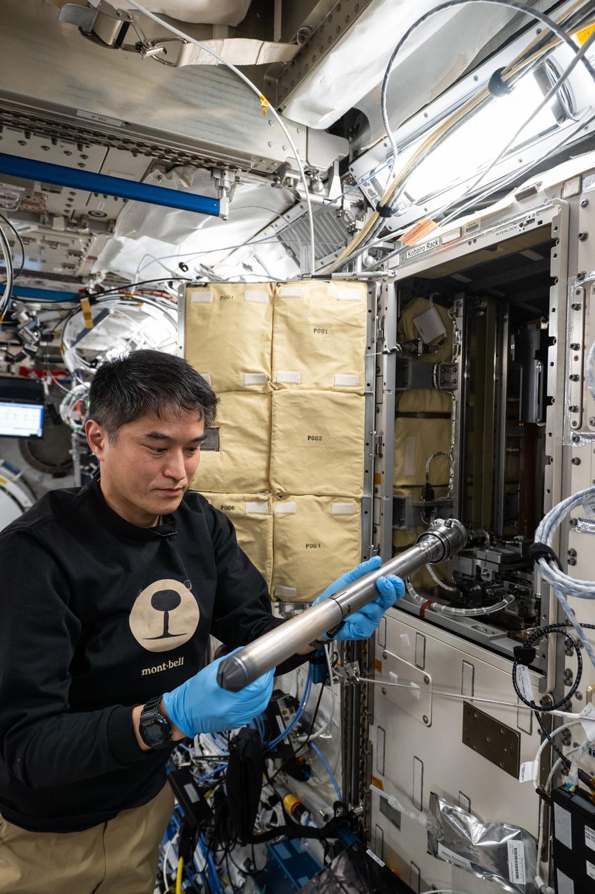
iss073e0383926 (July 4, 2025) --- JAXA (Japan Aerospace Exploration Agency) astronaut and Expedition 73 Commander Takuya Onishi removes experiment hardware and sample cartridges from inside the Kibo laboratory module's Gradient Heating Furnace (GHF). The GHF is a research facility and a vacuum furnace that can safely heat samples up to a maximum temperature of 1,600 degrees Celsius and is used for the production of high quality crystals in new semiconductor materials.
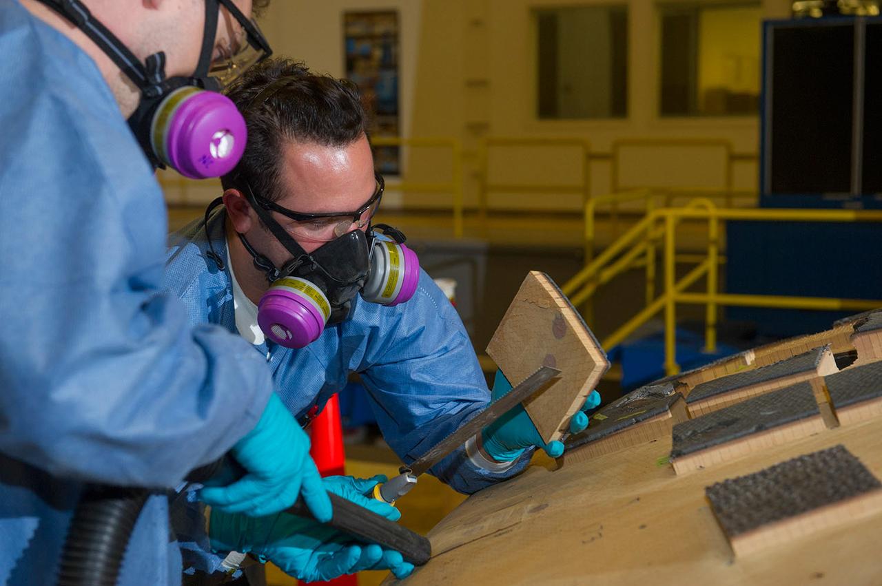
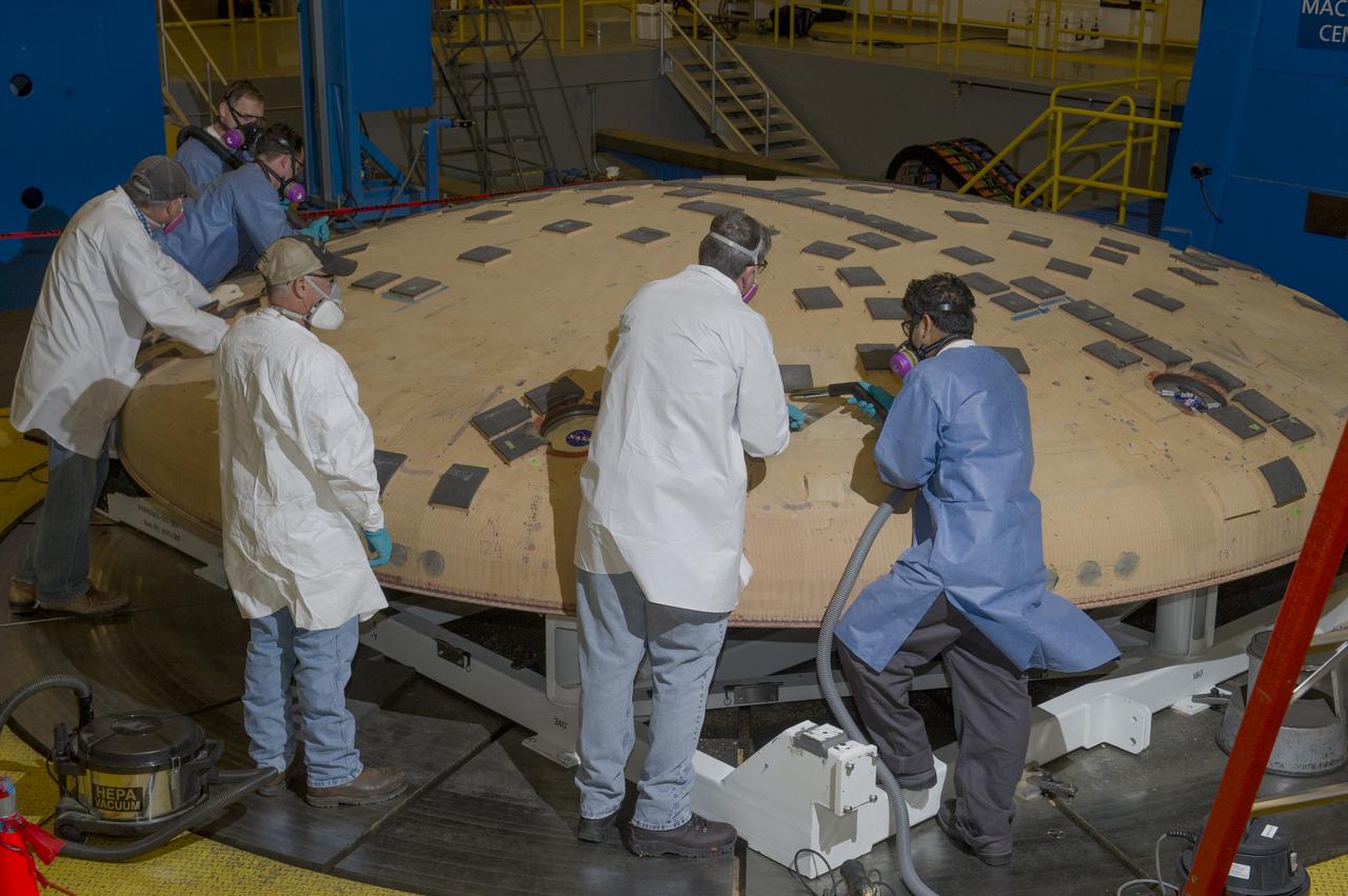
Engineers from NASA's Ames Research Center at Moffett Field, California, and Marshall Space Flight Center in Huntsville, Alabama, remove samples on May 4, 2015, from Orion's heat shield which flew on Exploration Flight Test-1 (EFT-1) in 2014. The heat shield protected the spacecraft from temperatures reaching 4000 degrees F. Part of Batch image transfer from Flickr.
Engineers from NASA's Ames Research Center at Moffett Field, California, and Marshall Space Flight Center in Huntsville, Alabama, remove samples on May 4, 2015, from Orion's heat shield which flew on Exploration Flight Test-1 (EFT-1) in 2014. The heat shield protected the spacecraft from temperatures reaching 4000 degrees F. Part of Batch image transfer from Flickr.
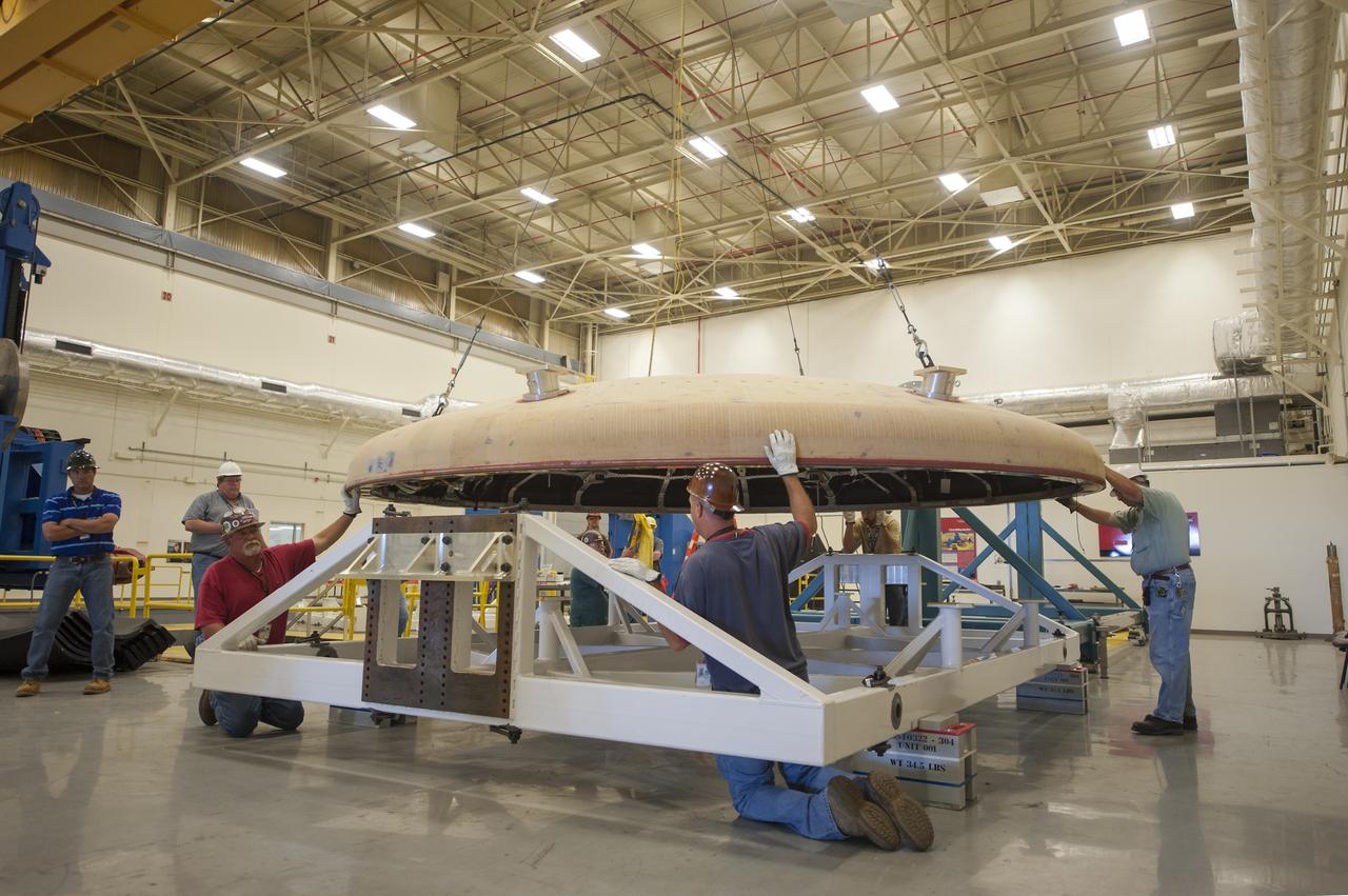
THE ORION HEAT SHIELD, WHICH WAS AT NASA’S MARSHALL SPACE FLIGHT CENTER FROM MARCH-MAY 2015 FOR ENGINEERING AND ANALYSIS, IS READIED FOR DEPARTURE AT THE END OF ITS STAY. THE HEAT SHIELD’S ABLATED SURFACE MATERIAL WAS REMOVED AT MARSHALL FOR ANALYSIS, USING THE CENTER’S STATE-OF-THE-ART SEVEN-AXIS MILLING MACHINE. IT NEXT WILL GO TO NASA’S LANGLEY RESEARCH CENTER FOR WATER-IMPACT TESTING. NASA’S JOHNSON SPACE CENTER LEADS THE ORION PROGRAM FOR NASA.
Engineers from NASA's Ames Research Center at Moffett Field, California, and Marshall Space Flight Center in Huntsville, Alabama, remove samples on May 4, 2015, from Orion's heat shield which flew on Exploration Flight Test-1 (EFT-1) in 2014. The heat shield protected the spacecraft from temperatures reaching 4000 degrees F. Part of Batch image transfer from Flickr.
THE ORION HEAT SHIELD, WHICH WAS AT NASA’S MARSHALL SPACE FLIGHT CENTER FROM MARCH-MAY 2015 FOR ENGINEERING AND ANALYSIS, IS READIED FOR DEPARTURE AT THE END OF ITS STAY. THE HEAT SHIELD’S ABLATED SURFACE MATERIAL WAS REMOVED AT MARSHALL FOR ANALYSIS, USING THE CENTER’S STATE-OF-THE-ART SEVEN-AXIS MILLING MACHINE. IT NEXT WILL GO TO NASA’S LANGLEY RESEARCH CENTER FOR WATER-IMPACT TESTING. NASA’S JOHNSON SPACE CENTER LEADS THE ORION PROGRAM FOR NASA.
THE ORION HEAT SHIELD, WHICH WAS AT NASA’S MARSHALL SPACE FLIGHT CENTER FROM MARCH-MAY 2015 FOR ENGINEERING AND ANALYSIS, IS READIED FOR DEPARTURE AT THE END OF ITS STAY. THE HEAT SHIELD’S ABLATED SURFACE MATERIAL WAS REMOVED AT MARSHALL FOR ANALYSIS, USING THE CENTER’S STATE-OF-THE-ART SEVEN-AXIS MILLING MACHINE. IT NEXT WILL GO TO NASA’S LANGLEY RESEARCH CENTER FOR WATER-IMPACT TESTING. NASA’S JOHNSON SPACE CENTER LEADS THE ORION PROGRAM FOR NASA.
Engineers from NASA's Ames Research Center at Moffett Field, California, and Marshall Space Flight Center in Huntsville, Alabama, remove samples on May 4, 2015, from Orion's heat shield which flew on Exploration Flight Test-1 (EFT-1) in 2014. The heat shield protected the spacecraft from temperatures reaching 4000 degrees F. Part of Batch image transfer from Flickr.
Engineers from NASA's Ames Research Center at Moffett Field, California, and Marshall Space Flight Center in Huntsville, Alabama, remove samples on May 4, 2015, from Orion's heat shield which flew on Exploration Flight Test-1 (EFT-1) in 2014. The heat shield protected the spacecraft from temperatures reaching 4000 degrees F. Part of Batch image transfer from Flickr.
Engineers from NASA's Ames Research Center at Moffett Field, California, and Marshall Space Flight Center in Huntsville, Alabama, remove samples on May 4, 2015, from Orion's heat shield which flew on Exploration Flight Test-1 (EFT-1) in 2014. The heat shield protected the spacecraft from temperatures reaching 4000 degrees F. Part of Batch image transfer from Flickr.
THE ORION HEAT SHIELD, WHICH WAS AT NASA’S MARSHALL SPACE FLIGHT CENTER FROM MARCH-MAY 2015 FOR ENGINEERING AND ANALYSIS, IS READIED FOR DEPARTURE AT THE END OF ITS STAY. THE HEAT SHIELD’S ABLATED SURFACE MATERIAL WAS REMOVED AT MARSHALL FOR ANALYSIS, USING THE CENTER’S STATE-OF-THE-ART SEVEN-AXIS MILLING MACHINE. IT NEXT WILL GO TO NASA’S LANGLEY RESEARCH CENTER FOR WATER-IMPACT TESTING. NASA’S JOHNSON SPACE CENTER LEADS THE ORION PROGRAM FOR NASA.
Engineers from NASA's Ames Research Center at Moffett Field, California, and Marshall Space Flight Center in Huntsville, Alabama, remove samples on May 4, 2015, from Orion's heat shield which flew on Exploration Flight Test-1 (EFT-1) in 2014. The heat shield protected the spacecraft from temperatures reaching 4000 degrees F. Part of Batch image transfer from Flickr.
THE ORION HEAT SHIELD, WHICH WAS AT NASA’S MARSHALL SPACE FLIGHT CENTER FROM MARCH-MAY 2015 FOR ENGINEERING AND ANALYSIS, IS READIED FOR DEPARTURE AT THE END OF ITS STAY. THE HEAT SHIELD’S ABLATED SURFACE MATERIAL WAS REMOVED AT MARSHALL FOR ANALYSIS, USING THE CENTER’S STATE-OF-THE-ART SEVEN-AXIS MILLING MACHINE. IT NEXT WILL GO TO NASA’S LANGLEY RESEARCH CENTER FOR WATER-IMPACT TESTING. NASA’S JOHNSON SPACE CENTER LEADS THE ORION PROGRAM FOR NASA.
THE ORION HEAT SHIELD, WHICH WAS AT NASA’S MARSHALL SPACE FLIGHT CENTER FROM MARCH-MAY 2015 FOR ENGINEERING AND ANALYSIS, IS READIED FOR DEPARTURE AT THE END OF ITS STAY. THE HEAT SHIELD’S ABLATED SURFACE MATERIAL WAS REMOVED AT MARSHALL FOR ANALYSIS, USING THE CENTER’S STATE-OF-THE-ART SEVEN-AXIS MILLING MACHINE. IT NEXT WILL GO TO NASA’S LANGLEY RESEARCH CENTER FOR WATER-IMPACT TESTING. NASA’S JOHNSON SPACE CENTER LEADS THE ORION PROGRAM FOR NASA.
THE ORION HEAT SHIELD, WHICH WAS AT NASA’S MARSHALL SPACE FLIGHT CENTER FROM MARCH-MAY 2015 FOR ENGINEERING AND ANALYSIS, IS READIED FOR DEPARTURE AT THE END OF ITS STAY. THE HEAT SHIELD’S ABLATED SURFACE MATERIAL WAS REMOVED AT MARSHALL FOR ANALYSIS, USING THE CENTER’S STATE-OF-THE-ART SEVEN-AXIS MILLING MACHINE. IT NEXT WILL GO TO NASA’S LANGLEY RESEARCH CENTER FOR WATER-IMPACT TESTING. NASA’S JOHNSON SPACE CENTER LEADS THE ORION PROGRAM FOR NASA.
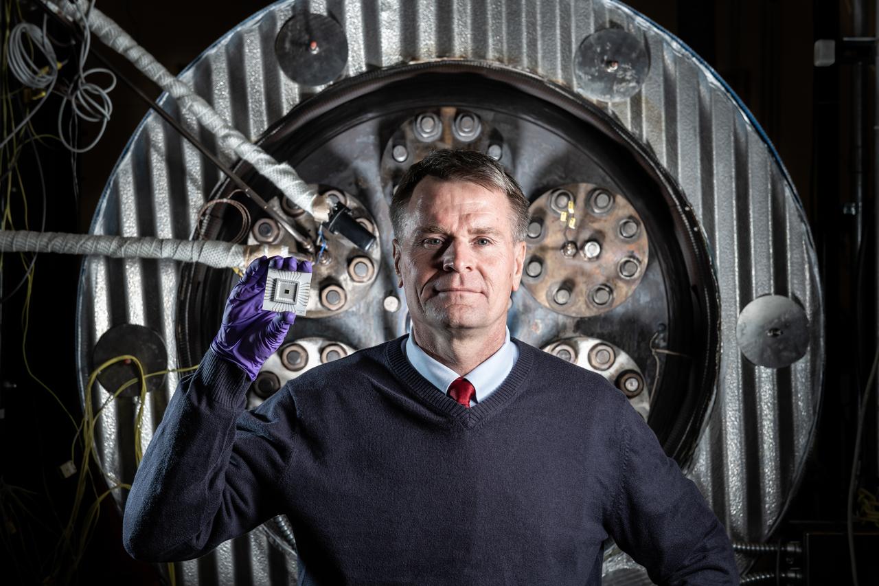
Phil Neudeck- Can Take the Heat When it comes to the heat of extreme environments like Venus, electronics can get fried within a few minutes of arrival. But NASA Researcher Phil Neudeck and his team have developed extremely durable silicon carbide semiconductor integrated circuits to survive those harsh conditions. After successfully testing the electronics in our high-pressure, high-temperature extreme environments chamber, there is now a path forward for Venus landers to survive and operate scientific experiments on the planet’s surface for longer durations.
THE ORION HEAT SHIELD, WHICH WAS AT NASA’S MARSHALL SPACE FLIGHT CENTER FROM MARCH-MAY 2015 FOR ENGINEERING AND ANALYSIS, IS READIED FOR DEPARTURE AT THE END OF ITS STAY. THE HEAT SHIELD’S ABLATED SURFACE MATERIAL WAS REMOVED AT MARSHALL FOR ANALYSIS, USING THE CENTER’S STATE-OF-THE-ART SEVEN-AXIS MILLING MACHINE. IT NEXT WILL GO TO NASA’S LANGLEY RESEARCH CENTER FOR WATER-IMPACT TESTING. NASA’S JOHNSON SPACE CENTER LEADS THE ORION PROGRAM FOR NASA.
THE ORION HEAT SHIELD, WHICH WAS AT NASA’S MARSHALL SPACE FLIGHT CENTER FROM MARCH-MAY 2015 FOR ENGINEERING AND ANALYSIS, IS READIED FOR DEPARTURE AT THE END OF ITS STAY. THE HEAT SHIELD’S ABLATED SURFACE MATERIAL WAS REMOVED AT MARSHALL FOR ANALYSIS, USING THE CENTER’S STATE-OF-THE-ART SEVEN-AXIS MILLING MACHINE. IT NEXT WILL GO TO NASA’S LANGLEY RESEARCH CENTER FOR WATER-IMPACT TESTING. NASA’S JOHNSON SPACE CENTER LEADS THE ORION PROGRAM FOR NASA.
Engineers from NASA's Ames Research Center at Moffett Field, California, and Marshall Space Flight Center in Huntsville, Alabama, remove samples on May 4, 2015, from Orion's heat shield which flew on Exploration Flight Test-1 (EFT-1) in 2014. The heat shield protected the spacecraft from temperatures reaching 4000 degrees F. Part of Batch image transfer from Flickr.
Engineers from NASA's Ames Research Center at Moffett Field, California, and Marshall Space Flight Center in Huntsville, Alabama, remove samples on May 4, 2015, from Orion's heat shield which flew on Exploration Flight Test-1 (EFT-1) in 2014. The heat shield protected the spacecraft from temperatures reaching 4000 degrees F. Part of Batch image transfer from Flickr.
THE ORION HEAT SHIELD, WHICH WAS AT NASA’S MARSHALL SPACE FLIGHT CENTER FROM MARCH-MAY 2015 FOR ENGINEERING AND ANALYSIS, IS READIED FOR DEPARTURE AT THE END OF ITS STAY. THE HEAT SHIELD’S ABLATED SURFACE MATERIAL WAS REMOVED AT MARSHALL FOR ANALYSIS, USING THE CENTER’S STATE-OF-THE-ART SEVEN-AXIS MILLING MACHINE. IT NEXT WILL GO TO NASA’S LANGLEY RESEARCH CENTER FOR WATER-IMPACT TESTING. NASA’S JOHNSON SPACE CENTER LEADS THE ORION PROGRAM FOR NASA.
THE ORION HEAT SHIELD, WHICH WAS AT NASA’S MARSHALL SPACE FLIGHT CENTER FROM MARCH-MAY 2015 FOR ENGINEERING AND ANALYSIS, IS READIED FOR DEPARTURE AT THE END OF ITS STAY. THE HEAT SHIELD’S ABLATED SURFACE MATERIAL WAS REMOVED AT MARSHALL FOR ANALYSIS, USING THE CENTER’S STATE-OF-THE-ART SEVEN-AXIS MILLING MACHINE. IT NEXT WILL GO TO NASA’S LANGLEY RESEARCH CENTER FOR WATER-IMPACT TESTING. NASA’S JOHNSON SPACE CENTER LEADS THE ORION PROGRAM FOR NASA.
THE ORION HEAT SHIELD, WHICH WAS AT NASA’S MARSHALL SPACE FLIGHT CENTER FROM MARCH-MAY 2015 FOR ENGINEERING AND ANALYSIS, IS READIED FOR DEPARTURE AT THE END OF ITS STAY. THE HEAT SHIELD’S ABLATED SURFACE MATERIAL WAS REMOVED AT MARSHALL FOR ANALYSIS, USING THE CENTER’S STATE-OF-THE-ART SEVEN-AXIS MILLING MACHINE. IT NEXT WILL GO TO NASA’S LANGLEY RESEARCH CENTER FOR WATER-IMPACT TESTING. NASA’S JOHNSON SPACE CENTER LEADS THE ORION PROGRAM FOR NASA.
THE ORION HEAT SHIELD, WHICH WAS AT NASA’S MARSHALL SPACE FLIGHT CENTER FROM MARCH-MAY 2015 FOR ENGINEERING AND ANALYSIS, IS READIED FOR DEPARTURE AT THE END OF ITS STAY. THE HEAT SHIELD’S ABLATED SURFACE MATERIAL WAS REMOVED AT MARSHALL FOR ANALYSIS, USING THE CENTER’S STATE-OF-THE-ART SEVEN-AXIS MILLING MACHINE. IT NEXT WILL GO TO NASA’S LANGLEY RESEARCH CENTER FOR WATER-IMPACT TESTING. NASA’S JOHNSON SPACE CENTER LEADS THE ORION PROGRAM FOR NASA.
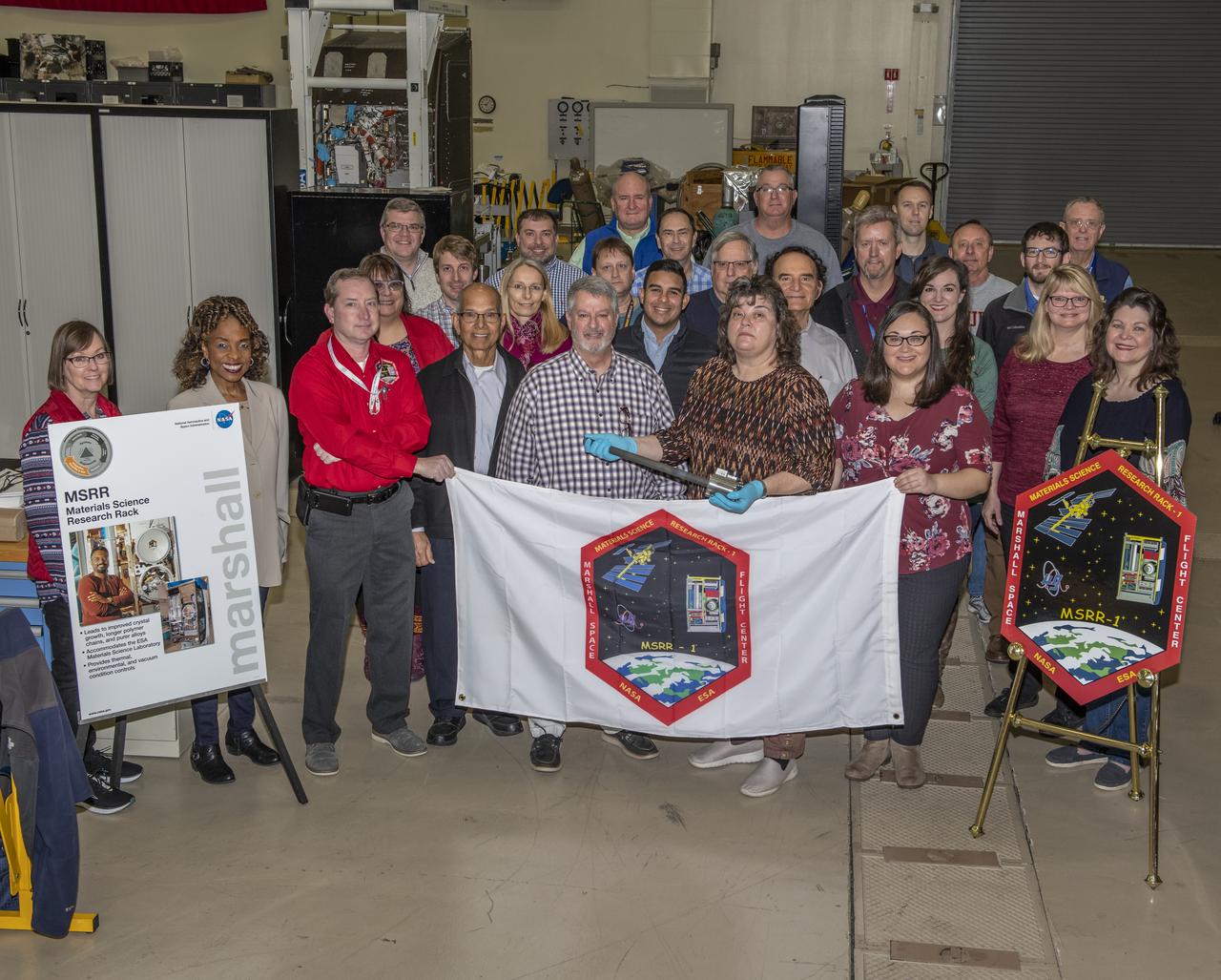
NASA's first Sample Cartridge Assembly (SCA) project designed and validated a payload containing a materials research sample in a sealed environment. The SCA was heated in the European Space Agency's (ESA) Low Gradient Furnace (LGF) that is housed inside the Material Science Research Rack (MSRR) located on the International Space Station (ISS). Sintered metals and crystal growth experiments in microgravity are examples of some of the types of materials research that may be performed with a SCA.
The Steam Plant at the National Advisory Committee for Aeronautics (NACA) Aircraft Engine Research Laboratory supplies steam to the major test facilities and office buildings. Steam is used for the Icing Research Tunnel's spray system and the Engine Research Building’s desiccant air dryers. In addition, its five boilers supply heat to various buildings and the cafeteria. Schirmer-Schneider Company built the $141,000 facility in the fall of 1942, and it has been in operation ever since.
NASA’s Lewis Research Center conducted extensive research programs in the 1960s and 1970s to develop systems that provide electrical power in space. One system, the Brayton cycle engine, converted solar thermal energy into electrical power. This system operated on a closed-loop Brayton thermodynamic cycle. The Brayton system relied on this large mirror to collect radiation from the sun. The mirror concentrated the Sun's rays on a heat storage receiver which warmed the Brayton system’s working fluid, a helium-xenon gas mixture. The heated fluid powered the system’s generator which produced power. In the mid-1960s Lewis researchers constructed this 30-foot diameter prototype of a parabolic solar mirror for the Brayton cycle system. The mirror had to be rigid, impervious to micrometeorite strikes, and lightweight. This mirror was comprised of twelve 1-inch thick magnesium plate sections that were coated with aluminum. The mirror could be compactly broken into its sections for launch.
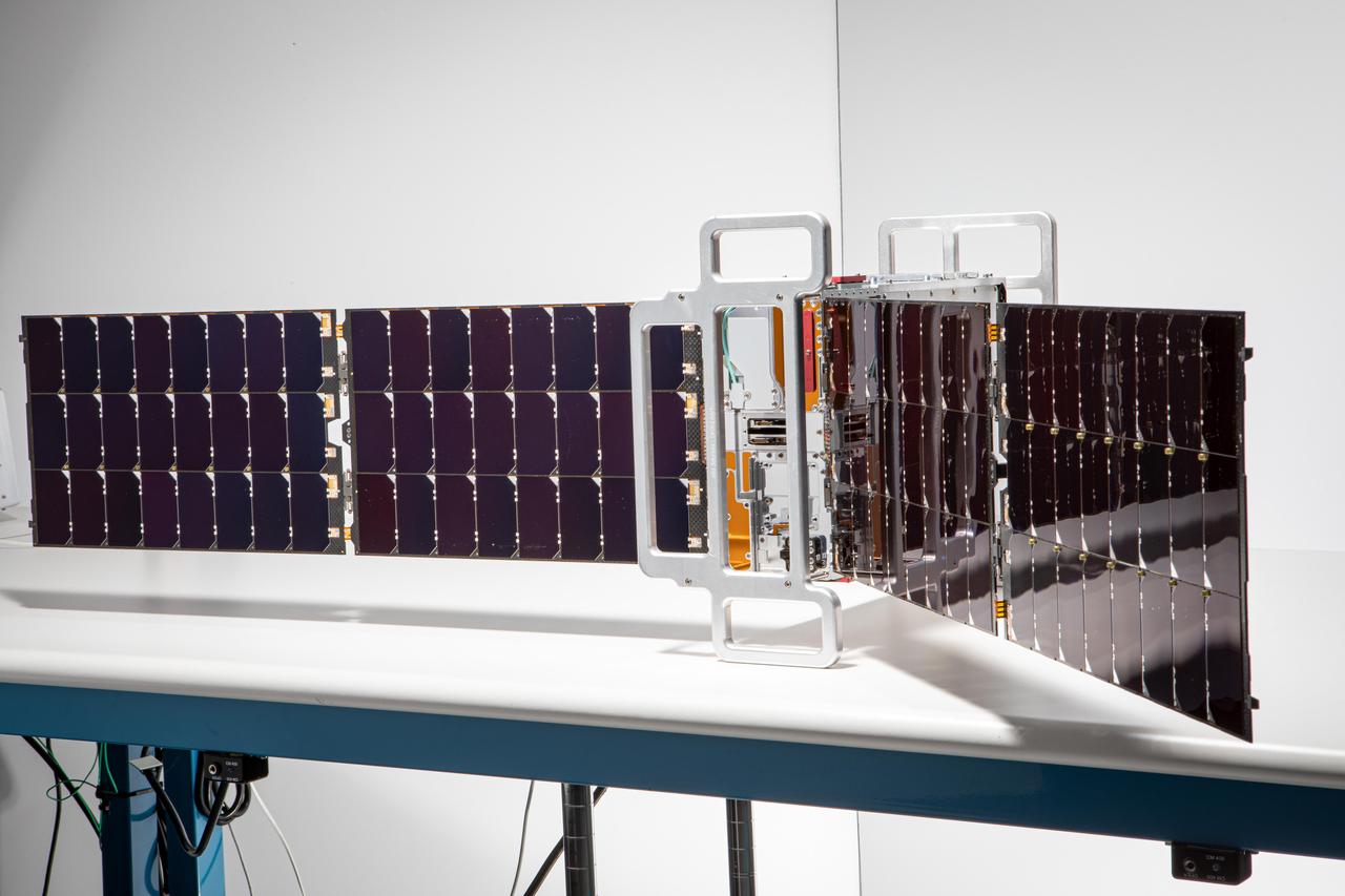
This image shows one of two shoebox-size satellites that make up NASA's Polar Radiant Energy in the Far-InfraRed Experiment (PREFIRE) mission. PREFIRE will measure the amount of heat Earth emits into space from two of the coldest, most remote regions on the planet. Data from the cube satellites, or CubeSats, will improve computer models researchers use to predict how Earth's ice, seas, and weather will change in a warming world. Earth absorbs a lot of the Sun's energy at the tropics, and weather and ocean currents transport that heat to the poles. Ice, snow, clouds, and other parts of the polar environment emit the heat into space, much of it in the form of far-infrared radiation. The difference between this incoming and outgoing heat helps to determines the planet's temperature and drives a dynamic system of climate and weather. But far-infrared emissions at the poles have never been systematically measured. This is where PREFIRE comes in. The crucial instrument on each spacecraft is a thermal infrared spectrometer, which will measure wavelengths of light in the far-infrared range. The mission will help researchers gain a clearer understanding of when and where Earth's poles emit far-infrared radiation, as well as how atmospheric water vapor and clouds influence the amount that escapes to space. https://photojournal.jpl.nasa.gov/catalog/PIA26186
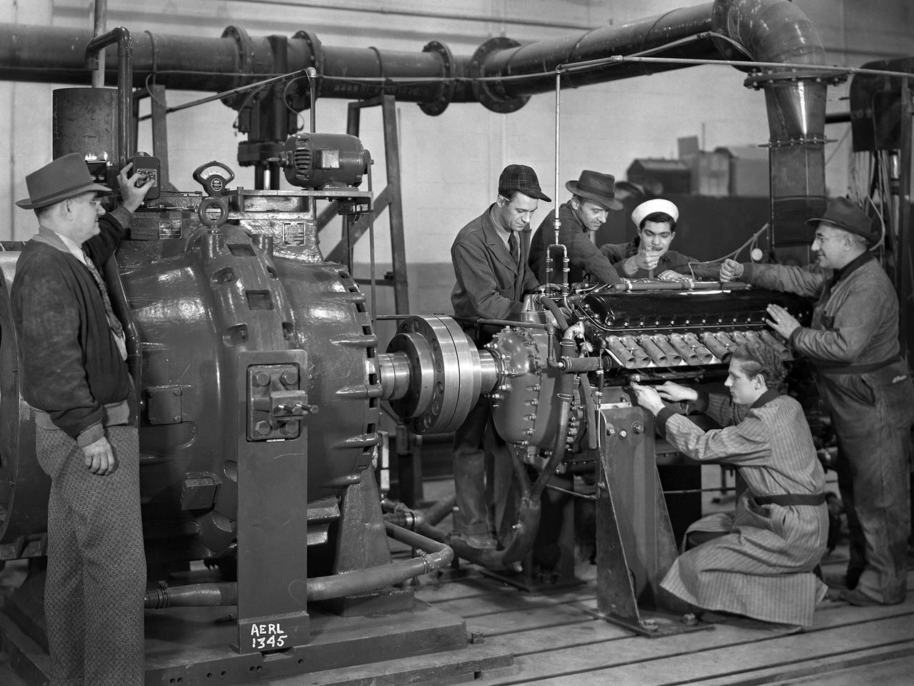
The first research assignment specifically created for the National Advisory Committee for Aeronautics’ (NACA) new Aircraft Engine Research Laboratory was the integration of a supercharger into the Allison V–1710 engine. The military was relying on the liquid-cooled V–1710 to power several types of World War II fighter aircraft and wanted to improve the engine's speed and altitude performance. Superchargers forced additional airflow into the combustion chamber, which increased the engine’s performance resulting in greater altitudes and speeds. They also generated excess heat that affected the engine cylinders, oil, and fuel. In 1943 the military tasked the new Aircraft Engine Research Laboratory to integrate the supercharger, improve the cooling system, and remedy associated engine knock. Three Allison engines were provided to the laboratory’s research divisions. One group was tasked with improving the supercharger performance, another analyzed the effect of the increased heat on knock in the fuel, one was responsible for improving the cooling system, and another would install the new components on the engine with minimal drag penalties. The modified engines were installed on this 2000-horsepower dynamotor stand in a test cell within the Engine Research Building. The researchers could run the engine at different temperatures, fuel-air ratios, and speeds. When the modifications were complete, the improved V–1710 was flight tested on a P–63A Kingcobra loaned to the NACA for this project.
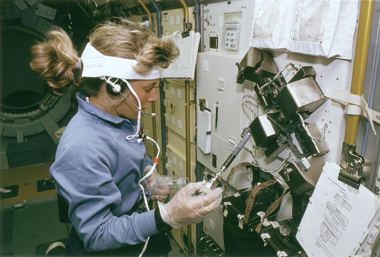
Space Shuttle Endeavour (STS-47) onboard photo of Astronaut N. Jan Davis at work at the Continuous Heating Furnace (CHF) in the Spacelab-J Science Module. Spacelab-J is a combined National Space Development Agency of Japan (NASDA) and NASA mission. The objectives included life sciences, microgravity and technology research.
L65-5505 In the Gas Dynamics Laboratory, completed in 1951, researchers explored basic aerodynamic, heating and fluid-mechanical problems in the speed range from Mach 1.5 to Mach 8.0. Photograph published in Engineer in Charge: A History of the Langley Aeronautical Laboratory, 1917-1958 by James R. Hansen. Page 348.

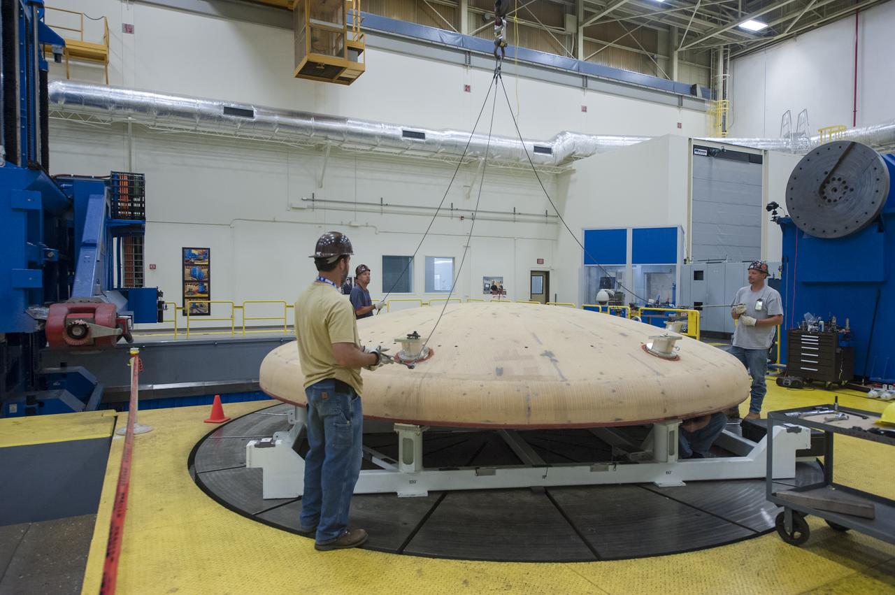
Engineers at NASA’s Langley Research Center in Hampton, Virginia, install test dummies into the seats of an Orion test article on Feb. 26, 2016. The capsule, coupled with the heat shield from the spacecraft’s first flight, will be used for water-impact testing to simulate what astronauts will experience when landing in the Pacific Ocean during a real mission.
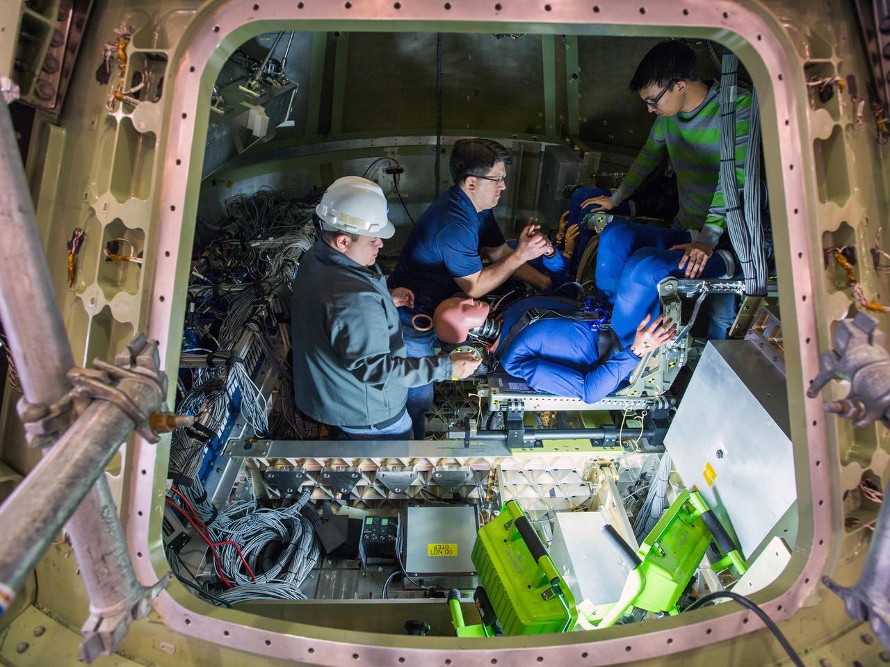
Engineers at NASA’s Langley Research Center in Hampton, Virginia, install test dummies into the seats of an Orion test article on Feb. 26, 2016. The capsule, coupled with the heat shield from the spacecraft’s first flight, will be used for water-impact testing to simulate what astronauts will experience when landing in the Pacific Ocean during a real mission.

Engineers at NASA’s Langley Research Center in Hampton, Virginia, install test dummies into the seats of an Orion test article on Feb. 26, 2016. The capsule, coupled with the heat shield from the spacecraft’s first flight, will be used for water-impact testing to simulate what astronauts will experience when landing in the Pacific Ocean during a real mission.

NASA Officials gather at Ames Research Center to discuss Spaceship development progress. Constellation is developing the Orion spacecraft and Ares rockets to support an American return to the moon by 2020. Speaker James Reuther, ARC, leader of the Advanced Development Thermal rotection Systems (heat shield) project for the Orion Crew Exploration Vehicle
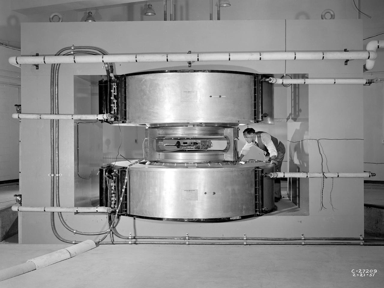
Researcher James Blue examines the new cyclotron at the National Advisory Committee for Aeronautics (NACA) Lewis Flight Propulsion Laboratory. Researchers at NACA Lewis began postulating about the use of atomic power for propulsion immediately after World War II. The NACA concentrated its efforts on the study of high temperature materials and heat transfer since it did not have access to the top secret fission information. The military studied the plausibility of nuclear propulsion for aircraft in the late 1940s. The military program was cancelled after four years without any breakthroughs, but the Atomic Energy Commission took on the effort in 1951. The NACA Lewis laboratory was expanding its nuclear-related research during this period. In 1948, Lewis engineers were assigned to the Oak Ridge National Laboratory to obtain expertise in high temperature heat transfer and advanced materials technology. The following year a new 80-person Nuclear Reactor Division was created, and an in-house nuclear school was established to train these researchers. The cyclotron was built behind the Materials and Structures Laboratory to support thermodynamic and materials research for both nuclear aircraft and nuclear rockets. The original NACA Lewis cyclotron was used to accelerate two kinds of particles. To better match the space radiation environment, the cyclotron was later modified to accelerate particles of the newly-discovered Van Allen radiation belts.

These photos show how teams at NASA’s Marshall Space Flight Center in Huntsville, Alabama, are testing an innovative approach to achieve zero boiloff storage of liquid hydrogen using two stages of active cooling, which could prevent the loss of valuable propellant during future long-duration spaceflight missions. Test teams installed the propellant tank in Test Stand 300 at NASA Marshall in early June, and the 90-day test campaign is scheduled to conclude in September. The tank is wrapped in a multi-layer insulation blanket that includes a thin aluminum heat shield fitted between layers. A second set of tubes, carrying helium at about minus 298 Fahrenheit, is integrated into the shield. This intermediate cooling layer intercepts and rejects incoming heat before it reaching the tank, easing the heat load on the tube-on-tank system. The Cryogenic Fluid Management Portfolio Project is a cross-agency team based at NASA Marshall and the agency’s Glenn Research Center in Cleveland. The cryogenic portfolio’s work is under NASA’s Technology Demonstration Missions Program, part of NASA’s Space Technology Mission Directorate, and is comprised of more than 20 individual technology development activities. For more information, contact NASA Marshall’s Office of Communications at 256-544-0034.
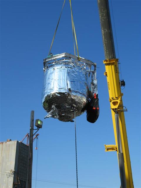
These photos show how teams at NASA’s Marshall Space Flight Center in Huntsville, Alabama, are testing an innovative approach to achieve zero boiloff storage of liquid hydrogen using two stages of active cooling, which could prevent the loss of valuable propellant during future long-duration spaceflight missions. Test teams installed the propellant tank in Test Stand 300 at NASA Marshall in early June, and the 90-day test campaign is scheduled to conclude in September. The tank is wrapped in a multi-layer insulation blanket that includes a thin aluminum heat shield fitted between layers. A second set of tubes, carrying helium at about minus 298 Fahrenheit, is integrated into the shield. This intermediate cooling layer intercepts and rejects incoming heat before it reaching the tank, easing the heat load on the tube-on-tank system. The Cryogenic Fluid Management Portfolio Project is a cross-agency team based at NASA Marshall and the agency’s Glenn Research Center in Cleveland. The cryogenic portfolio’s work is under NASA’s Technology Demonstration Missions Program, part of NASA’s Space Technology Mission Directorate, and is comprised of more than 20 individual technology development activities. For more information, contact NASA Marshall’s Office of Communications at 256-544-0034.
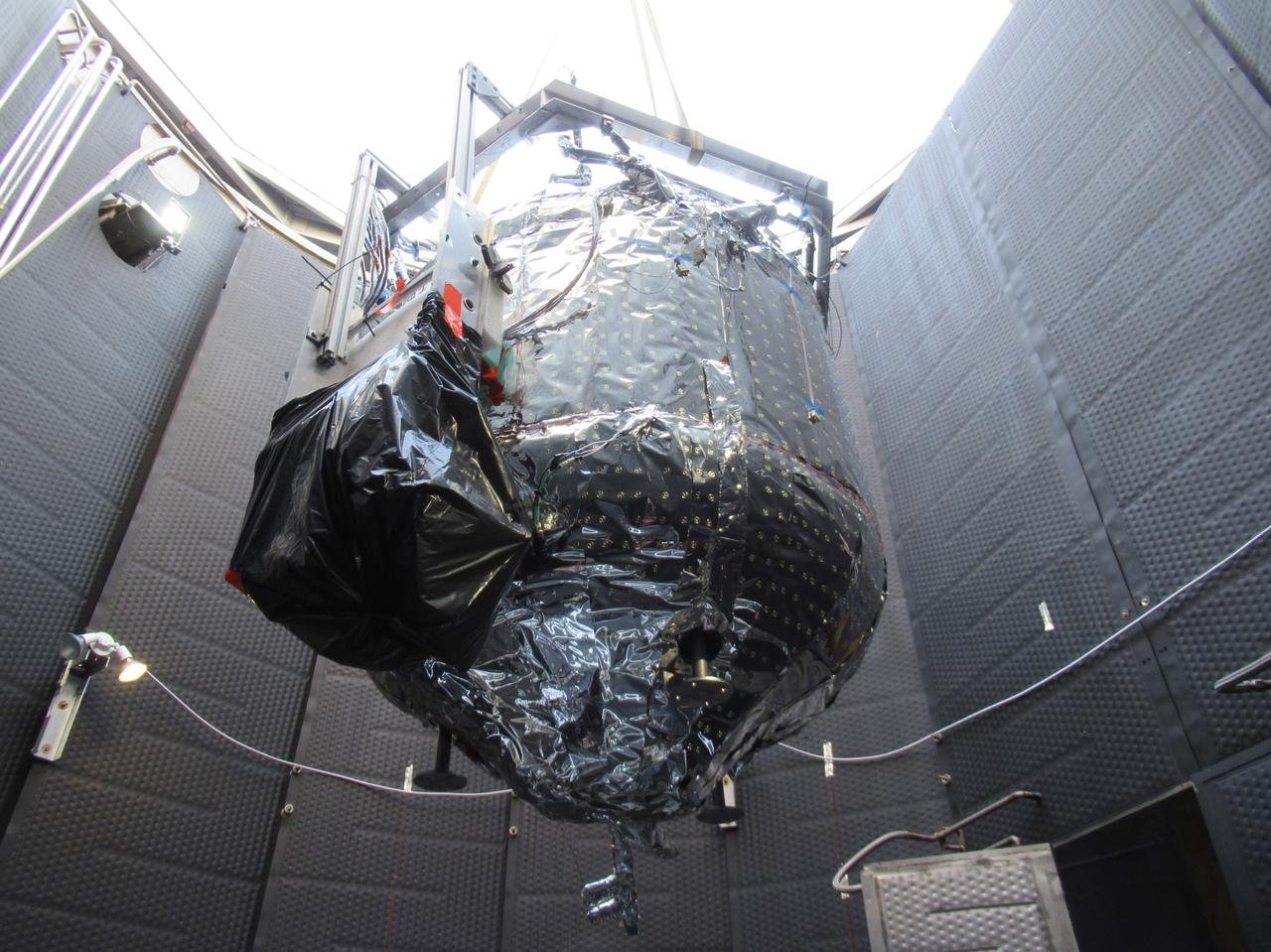
These photos show how teams at NASA’s Marshall Space Flight Center in Huntsville, Alabama, are testing an innovative approach to achieve zero boiloff storage of liquid hydrogen using two stages of active cooling, which could prevent the loss of valuable propellant during future long-duration spaceflight missions. Test teams installed the propellant tank in Test Stand 300 at NASA Marshall in early June, and the 90-day test campaign is scheduled to conclude in September. The tank is wrapped in a multi-layer insulation blanket that includes a thin aluminum heat shield fitted between layers. A second set of tubes, carrying helium at about minus 298 Fahrenheit, is integrated into the shield. This intermediate cooling layer intercepts and rejects incoming heat before it reaching the tank, easing the heat load on the tube-on-tank system. The Cryogenic Fluid Management Portfolio Project is a cross-agency team based at NASA Marshall and the agency’s Glenn Research Center in Cleveland. The cryogenic portfolio’s work is under NASA’s Technology Demonstration Missions Program, part of NASA’s Space Technology Mission Directorate, and is comprised of more than 20 individual technology development activities. For more information, contact NASA Marshall’s Office of Communications at 256-544-0034.
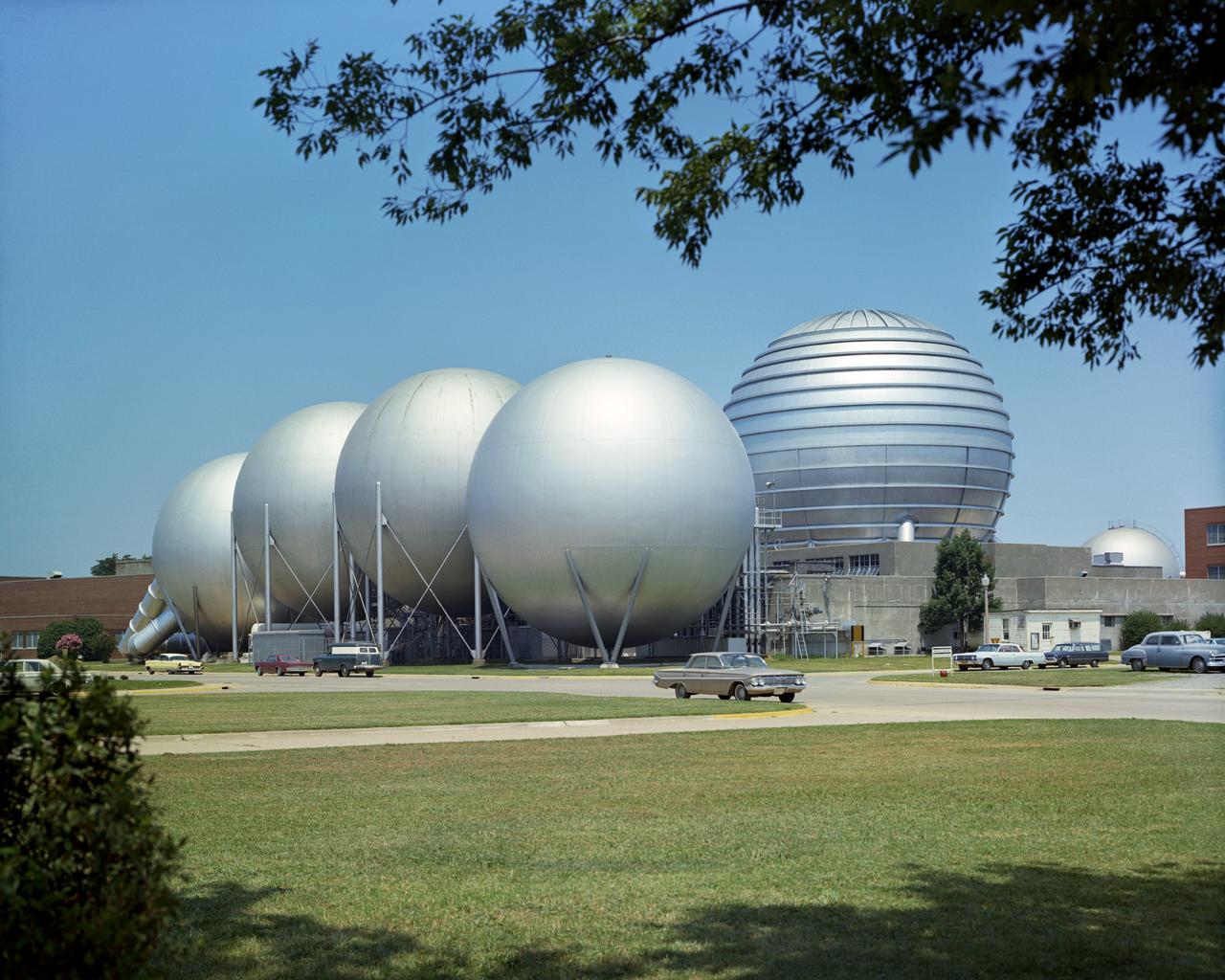
Aerial view of Gasdynamics facility in 1964 and the 20 inch helium tunnel Part of the Thermal Protection Laboratory used to research materials for heat shield applications and for aerodynamic heating and materials studies of vehicles in planetary atmospheres. This laboratory is comprised of five separate facilities: an Aerodynamic Heating Tunnel, a Heat Transfer Tunnel, two Supersonic Turbulent Ducts, and a High-Power CO2 Gasdynamic Laser. All these facilities are driven by arc-heaters, with the exception of the large, combustion-type laser. The arc-heated facilities are powered by a 20 Megawatt DC power supply. Their effluent gas stream (test gases; Air, N2, He, CO2 and mixtures; flow rates from 0.05 to 5.0 lbs/sec) discharges into a five-stage stream-ejector-driven vacuum system. The vacuum system and power supply are common to the test faciities in building N-238. All of the facilities have high pressure water available at flow rates up to 4, 000 gals/min. The data obtained from these facilities are recorded on magnetic tape or oscillographs. All forms of data can be handled whether from thermo-couples, pressure cells, pyrometers, or radiometers, etc. in addition, closed circuit T. V. monitors and various film cameras are available. (operational since 1962)
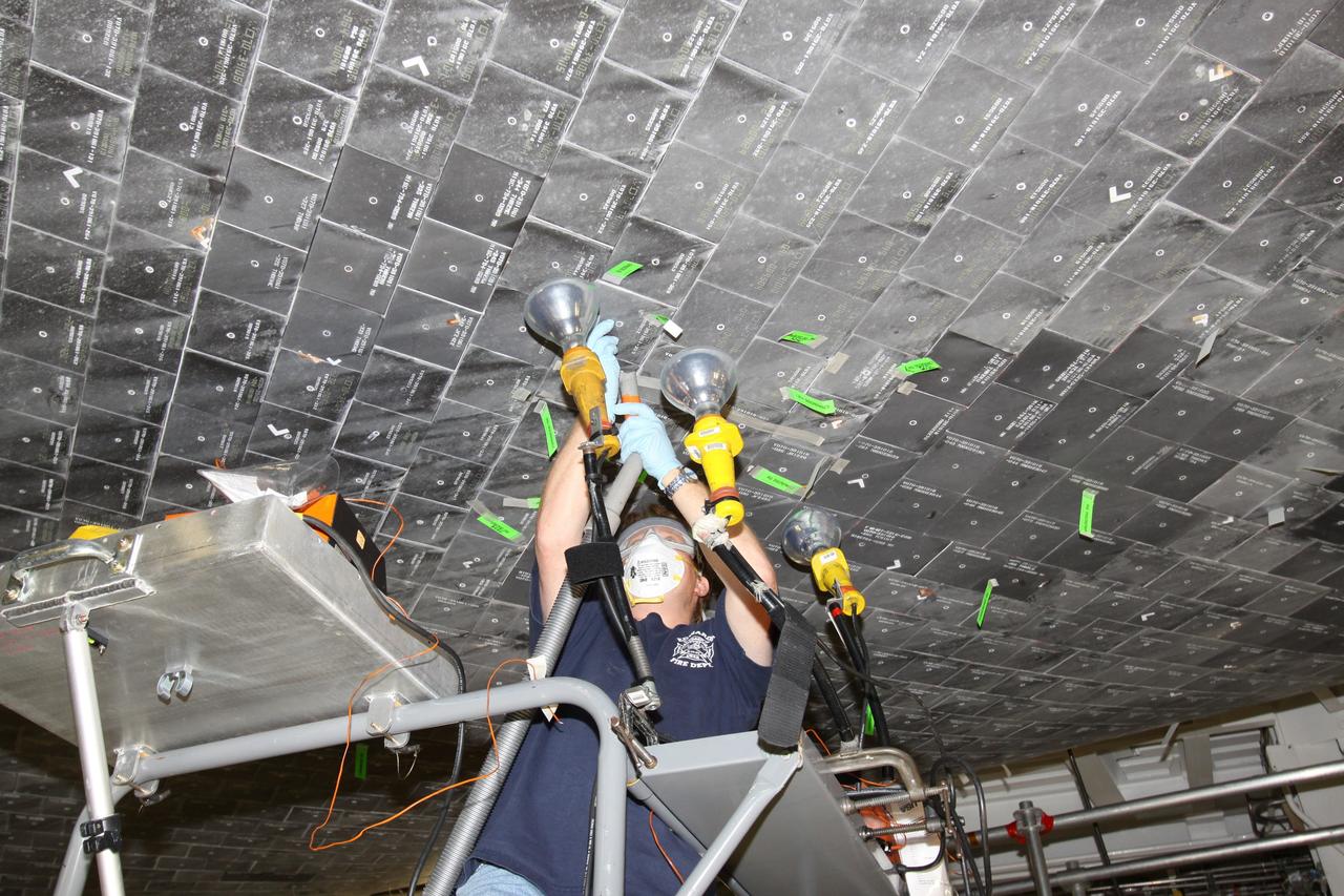
CAPE CANAVERAL, Fla. - In Orbiter Processing Facility Bay 1 at NASA's Kennedy Space Center in Florida, heat lamps assist United Space Alliance technician Jeff Holmes in a putty repair on some of the high-temperature reusable surface insulation tiles, or HRSI tiles, on the lower forward fuselage of space shuttle Atlantis. An average of 125 tiles are replaced after each mission either due to handling damage or accumulated repairs. These black tiles are optimized for maximum emissivity, which means they lose heat faster than white tiles. This property is required to maximize heat rejection during the hot phase of reentry. Atlantis next is slated to deliver an Integrated Cargo Carrier and Russian-built Mini Research Module to the International Space Station on the STS-132 mission. Launch is targeted for May 14, 2010. Photo credit: NASA/Jack Pfaller
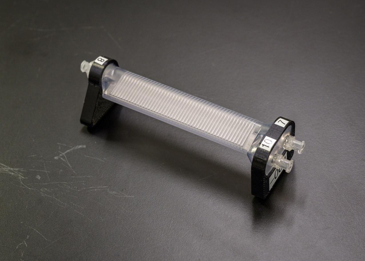
jsc2023e010169 (1/30/2023) --- CapiSorb Visible System flight unit capillary condensing heat exchanger (CCHX) in N240 room 133B. The CapiSorb Visible System will be launched on SpaceX CRS-27 in March 2023 to the International Space Station to demonstrate a liquid sorbent-based system that leverages the advantages of liquid control through capillary action to remove carbon dioxide from crewed atmospheres...The CapiSorb Visible System Capillary Condensing Heat Exchanger, shown here pre-flight, uses capillary surfaces and active cooling to condense water vapor from heated, humid air during microgravity experimentation. The capillary surfaces enable control and passive transport of fluids. The CapiSorb Visible System investigation demonstrates a liquid control using capillary forces, over a range of liquid properties that are characteristic of liquid carbon dioxide sorbents. Image courtesy of NASA's Ames Research Center.