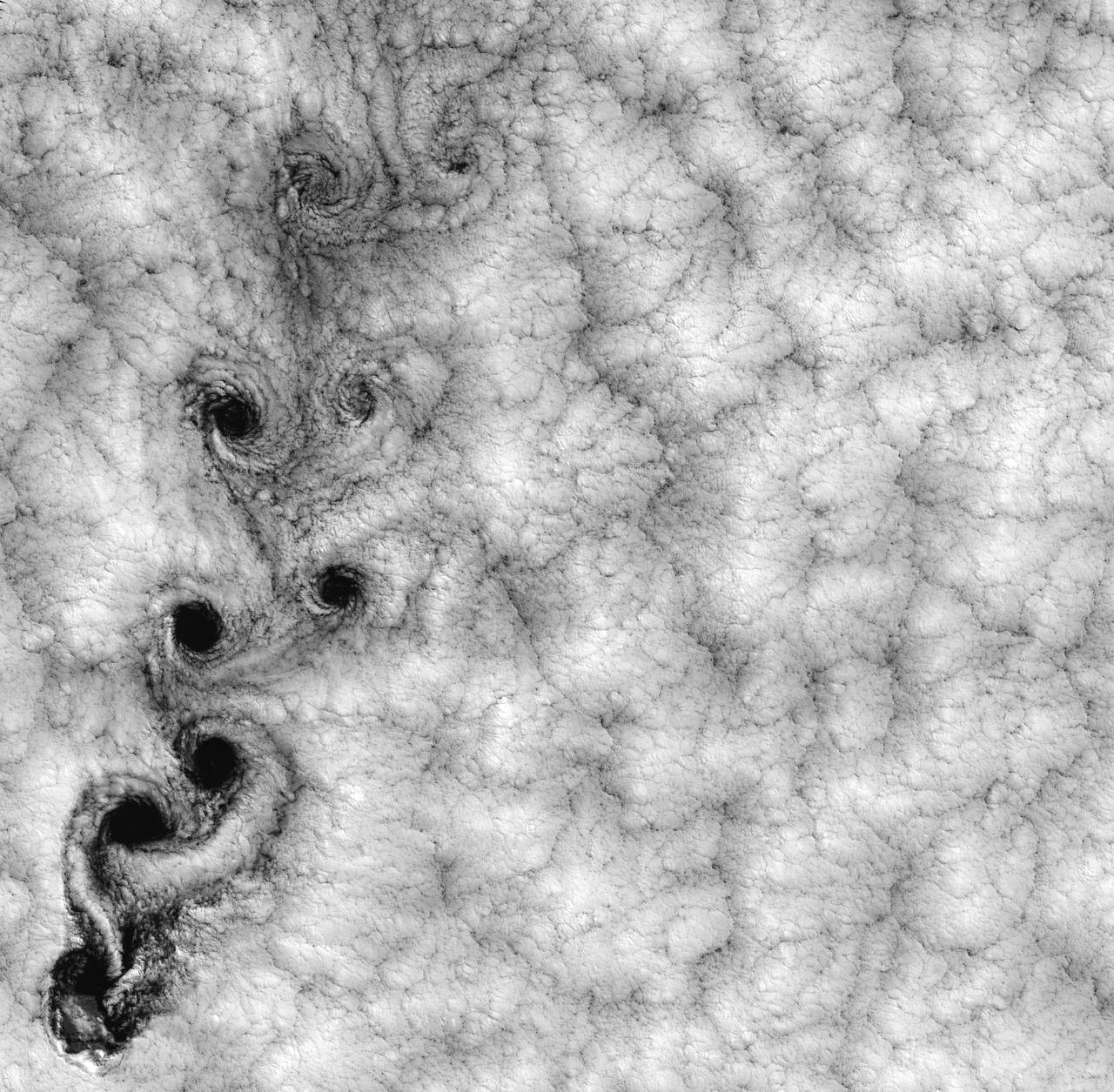
Justin Hall, left, chief pilot of small unmanned aircraft systems, carries the atmospheric probe at NASA’s Armstrong Flight Research Center in Edwards, California. The probe, which was designed and built at the center, flew after release from a quad rotor remotely piloted aircraft on Oct. 22, 2024, above Rogers Dry Lake, a flight area adjacent to the NASA center. At right, Justin Link, unmanned aircraft systems pilot, checks out the controllers for the two aircraft.
Atmospheric Probe Shows Promise in Test Flight
Scaled Composites' Doug Shane examines the screen of his ground control station during tests in New Mexico. Shane used this configuration as the ground control station to remotely pilot the Proteus aircraft during a NASA sponsored series of tests.
A pilot for General Atomics guides the Altair remotely operated aircraft from a ground control station using both visual and telemetered data.
ED05-0082-04
One of NASA's unmanned, remotely controlled aircraft, the Perseus B, is seen here before its first flight at the Dryden Flight Research Center, Edwards, California.
Perseus B on lakebed before first flight
The control room for the remotely piloted X-56A has a feature that most do not – the pilot and co-pilot are in the front of the room, seen at left. The X-56A team has successfully suppressed flutter, which is a potentially destructive oscillation, with a classical and a modern controller. The controllers are essentially mathematical ways of directing the aircraft.
X-56A Control Room is Uncommon
Technicians check instrumentation and systems on NASA 808, a PA-30 aircraft, prior to a research flight. The aircraft was used as the testbed in development of control systems for remotely piloted vehicles that were "flown" from the ground. The concept led to highly successful programs such as the HiMAT and the subscale F-15 remotely piloted vehicles. Over the years, NASA 808 has also been used for spin and stall research related to general aviation aircraft and also research to alleviate wake vortices behind large jetliners.  This 1980 photograph taken inside a hangar shows technicians measuring moment of inertia.
PA-30 Twin Comanche - NASA 808 in hangar
Engineers at NASA‘s Armstrong Flight Research Center sit in a control room to monitor the remotely-piloted Ikhana aircraft during a test flight. The test flight was used to validate key technologies and operations necessary to receive approval from the FAA’s to fly the aircraft in the National Airspace System June 12, 2018, without a safety chase aircraft.
NASAs Engineers in Mission Control Monitor Ikhana Aircraft During a Test Flight
CID (Controlled Imact Demonstrator) Aircraft lakebed skid.
EC84-31803
CID (Controlled Imact Demonstrator) Aircraft fireball after wing cutter impact.
EC84-31808
CID (Controlled Imact Demonstrator) Aircraft skid after wing cutter impact.
EC84-31806
CID (Controlled Imact Demonstrator) Aircraft prior to wing cutter impact during lakebed skid.
EC84-31805
CID (Controlled Imact Demonstrator) Aircraft in practice flight above target impact site with wing cutters.
EC84-31672A
CID (Controlled Imact Demonstrator) Aircraft fireball after wing cutter impact.
EC84-31809
CAPE CANAVERAL, Fla. – A remote-controlled aircraft flies during a competition with a unique set of sensors and software to conduct a mock search-and-rescue operation. The aircraft was assembled by a team of engineers from NASA's Kennedy Space Center. Teams from Johnson Space Center, Kennedy and Marshall Space Flight Center competed in the unmanned aerial systems event to evaluate designs and work by engineers learning new specialties. The competition took place at the Shuttle Landing Facility at Kennedy. Photo credit: NASA/Dmitri Gerondidakis
KSC-2013-3543
CAPE CANAVERAL, Fla. – A remote-controlled aircraft flies during a competition with a unique set of sensors and software to conduct a mock search-and-rescue operation. The aircraft was assembled by a team of engineers from NASA's Kennedy Space Center. Teams from Johnson Space Center, Kennedy and Marshall Space Flight Center competed in the unmanned aerial systems event to evaluate designs and work by engineers learning new specialties. The competition took place at the Shuttle Landing Facility at Kennedy. Photo credit: NASA/Dmitri Gerondidakis
KSC-2013-3542
CAPE CANAVERAL, Fla. – A remote-controlled aircraft takes off during a competition with a unique set of sensors and software to conduct a mock search-and-rescue operation. The aircraft was assembled by a team of engineers from NASA's Kennedy Space Center. Teams from Johnson Space Center, Kennedy and Marshall Space Flight Center competed in the unmanned aerial systems event to evaluate designs and work by engineers learning new specialties. The competition took place at the Shuttle Landing Facility at Kennedy. Photo credit: NASA/Dmitri Gerondidakis
KSC-2013-3540
CAPE CANAVERAL, Fla. – A remote-controlled aircraft flies during a competition with a unique set of sensors and software to conduct a mock search-and-rescue operation. The aircraft was assembled by a team of engineers from NASA's Marshall Space Flight Center. Teams from Johnson Space Center, Kennedy Space Center and Marshall competed in the unmanned aerial systems event to evaluate designs and work by engineers learning new specialties. The competition took place at the Shuttle Landing Facility at Kennedy. Photo credit: NASA/Dmitri Gerondidakis
KSC-2013-3546
CAPE CANAVERAL, Fla. – A remote-controlled aircraft flies during a competition with a unique set of sensors and software to conduct a mock search-and-rescue operation. The aircraft was assembled by a team of engineers from NASA's Kennedy Space Center. Teams from Johnson Space Center, Kennedy and Marshall Space Flight Center competed in the unmanned aerial systems event to evaluate designs and work by engineers learning new specialties. The competition took place at the Shuttle Landing Facility at Kennedy. Photo credit: NASA/Dmitri Gerondidakis
KSC-2013-3541
Dryden Flight Research Center's Piper PA-30 Twin Commanche, which helped validate the RPRV concept, descends to a remotely controlled landing on Rogers Dry Lake, unassisted by the onboard pilot. A Piper PA-30 Twin Commanche, known as NASA 808, was used at the NASA Dryden Flight Research Center as a rugged workhorse in a variety of research projects associated with both general aviation and military projects.  In the early 1970s, the PA-30, serial number 301498, was used to test a flight technique used to fly Remotely Piloted Research Vehicles (RPRV's). The technique was first tested with the cockpit windows of the light aircraft blacked out while the pilot flew the aircraft utilizing a television monitor which gave him a "pilot's eye" view ahead of the aircraft. Later pilots flew the aircraft from a ground cockpit, a procedure used with all RPRV's. TV and two-way telemetry allow the pilot to be in constant control of the aircraft. The apparatus mounted over the cockpit is a special fish eye lens camera, used to obtain images that are transmitted to the ground based cockpit. This project paved the way for sophisticated, highly successful research programs involving high risk spin, stall, and flight control conditions, such as the HiMAT and the subscale F-15 remotely piloted vehicles.  Over the years, NASA 808 has also been used for spin and stall research related to general aviation aircraft and also research to alleviate wake vortices behind large jetliners.
PA-30 Twin Comanche - NASA 808 in flight
CAPE CANAVERAL, Fla. – An engineer from NASA's Marshall Space Flight Center prep a remote-controlled aircraft for take-off. The aircraft is equipped with a unique set of sensors and software and was assembled by a team of engineers for a competition at the agency's Kennedy Space Center. Teams from Johnson Space Center and Marshall Space Flight Center joined the Kennedy team in competing in an unmanned aerial systems event to evaluate designs and work by engineers learning new specialties. The competition took place at the Shuttle Landing Facility at Kennedy. Photo credit: NASA/Dmitri Gerondidakis
KSC-2013-3545
CAPE CANAVERAL, Fla. – An engineer from NASA's Marshall Space Flight Center watches the landing of remote-controlled aircraft. The aircraft is equipped with a unique set of sensors and software and was assembled by a team of engineers for a competition at the agency's Kennedy Space Center. Teams from Johnson Space Center and Marshall Space Flight Center joined a Kennedy team in competing in an unmanned aerial systems event to evaluate designs and work by engineers learning new specialties. The competition took place at the Shuttle Landing Facility at Kennedy. Photo credit: NASA/Dmitri Gerondidakis
KSC-2013-3547
CAPE CANAVERAL, Fla. – Engineers from NASA's Kennedy Space Center prep a remote-controlled aircraft for take-off. The aircraft is equipped with a unique set of sensors and software and was assembled by a team of engineers for a competition at the agency's Kennedy Space Center. Teams from Johnson Space Center and Marshall Space Flight Center joined the Kennedy team in competing in an unmanned aerial systems event to evaluate designs and work by engineers learning new specialties. The competition took place at the Shuttle Landing Facility at Kennedy. Photo credit: NASA/Dmitri Gerondidakis
KSC-2013-3539
CAPE CANAVERAL, Fla. – Engineers from NASA's Marshall Space Flight Center prep a remote-controlled aircraft for take-off. The aircraft is equipped with a unique set of sensors and software and was assembled by a team of engineers for a competition at the agency's Kennedy Space Center. Teams from Johnson Space Center and Marshall Space Flight Center joined the Kennedy team in competing in an unmanned aerial systems event to evaluate designs and work by engineers learning new specialties. The competition took place at the Shuttle Landing Facility at Kennedy. Photo credit: NASA/Dmitri Gerondidakis
KSC-2013-3544
CAPE CANAVERAL, Fla. – Engineers from NASA's Kennedy Space Center prep a remote-controlled aircraft for take-off. The aircraft is equipped with a unique set of sensors and software and was assembled by a team of engineers for a competition at the agency's Kennedy Space Center. Teams from Johnson Space Center and Marshall Space Flight Center joined the Kennedy team in competing in an unmanned aerial systems event to evaluate designs and work by engineers learning new specialties. The competition took place at the Shuttle Landing Facility at Kennedy. Photo credit: NASA/Dmitri Gerondidakis
KSC-2013-3538
The atmospheric probe, right, flew after release from a quad rotor remotely piloted aircraft, left, on Oct. 22, 2024, above Rogers Dry Lake, a flight area adjacent to NASA’s Armstrong Flight Research Center in Edwards, California. The probe was designed and built at the center.
Atmospheric Probe Shows Promise in Test Flight
Powered by a laser beam directed at it from a center pedestal, a lightweight model plane makes the first flight of an aircraft powered by laser energy inside a building at NASA's Marshall Space Flight Center.
Powered by a laser beam directed at it from a pedestal, a model plane makes the first flight of an aircraft powered by laser energy inside a building at NASA Marshall.
NASA Dryden project engineer Dave Bushman carefully aims the optics of a laser device at a solar cell panel on a model aircraft during the first flight demonstration of an aircraft powered by laser light.
NASA Dryden's Dave Bushman aims the optics of a laser device at a panel on a model aircraft during the first flight demonstration of an aircraft powered by laser light.
With a laser beam centered on its panel of photovoltaic cells, a lightweight model plane makes the first flight of an aircraft powered by a laser beam inside a building at NASA Marshall Space Flight Center.
With a laser beam centered on its panel of photovoltaic cells, a model plane makes the first flight of an aircraft powered by a laser beam inside a building at NASA Marshall.
With a laser beam centered on its solar panel, a lightweight model aircraft is checked out by technician Tony Frakowiak and researcher Tim Blackwell before its power-beamed demonstration flight.
With a laser beam centered on its solar panel, a model aircraft is checked out by technician Tony Frakowiak and researcher Tim Blackwell before its power-beamed demonstration flight.
Controlled Impact Demonstration instrumented test dummies installed in plane.
EC84-28307
The Hyper III was a low-cost test vehicle for an advanced lifting-body shape. Like the earlier M2-F1, it was a "homebuilt" research aircraft, i.e., built at the Flight Research Center (FRC), later redesignated the Dryden Flight Research Center. It had a steel-tube frame covered with Dacron, a fiberglass nose, sheet aluminum fins, and a wing from an HP-11 sailplane. Construction was by volunteers at the FRC. Although the Hyper III was to be flown remotely in its initial tests, it was fitted with a cockpit for a pilot. On the Hyper III's only flight, it was towed aloft attached to a Navy SH-3 helicopter by a 400-foot cable. NASA research pilot Bruce Peterson flew the SH-3. After he released the Hyper III from the cable, NASA research pilot Milt Thompson flew the vehicle by radio control until the final approach when Dick Fischer took over control using a model-airplane radio-control box. The Hyper III flared, then landed and slid to a stop on Rogers Dry Lakebed.
ECN-2301
KENNEDY SPACE CENTER, FLA. -   On a tour of the KSC Beach Corrosion Test Site, Center Director Jim Kennedy (second from right) learns from Testbed Manager Louis MacDowell (right) about a project being undertaken for the U.S. Navy.  Being studied are nonchrome primers for aircraft.  At left are Lead Scientist Dr. Luz Marina Calle and  Dr. Paul Hintze, who is working on a graduate project for the National Research Council.  The KSC Beach Corrosion Test Site was established in the 1960s and has provided more than 30 years of historical information on the long-term performance of many materials in use at KSC and other locations around the world. Located 100 feet from the Atlantic Ocean approximately 1 mile south of the Space Shuttle launch sites, the test facility includes an atmospheric exposure site, a flowing seawater exposure site, and an on-site electrochemistry laboratory and monitoring station. The beach laboratory is used to conduct real-time corrosion experiments and provides for the remote monitoring of surrounding weather conditions. The newly added flowing seawater immersion facility provides for the immersion testing of materials and devices under controlled conditions.
KENNEDY SPACE CENTER, FLA. - On a tour of the KSC Beach Corrosion Test Site, Center Director Jim Kennedy (second from right) learns from Testbed Manager Louis MacDowell (right) about a project being undertaken for the U.S. Navy. Being studied are nonchrome primers for aircraft. At left are Lead Scientist Dr. Luz Marina Calle and Dr. Paul Hintze, who is working on a graduate project for the National Research Council. The KSC Beach Corrosion Test Site was established in the 1960s and has provided more than 30 years of historical information on the long-term performance of many materials in use at KSC and other locations around the world. Located 100 feet from the Atlantic Ocean approximately 1 mile south of the Space Shuttle launch sites, the test facility includes an atmospheric exposure site, a flowing seawater exposure site, and an on-site electrochemistry laboratory and monitoring station. The beach laboratory is used to conduct real-time corrosion experiments and provides for the remote monitoring of surrounding weather conditions. The newly added flowing seawater immersion facility provides for the immersion testing of materials and devices under controlled conditions.
KENNEDY SPACE CENTER, FLA. -   On a tour of the KSC Beach Corrosion Test Site, Testbed Manager Louis MacDowell (foreground) explains to Center Director Jim Kennedy (third from right) about a study being undertaken for the U.S. Navy: nonchrome primers for aircraft. At left is Lead Scientist Dr. Luz Marina Calle and behind MacDowell is Dr. Paul Hintze, who is working on a graduate project for the National Research Council.  The KSC Beach Corrosion Test Site was established in the 1960s and has provided more than 30 years of historical information on the long-term performance of many materials in use at KSC and other locations around the world. Located 100 feet from the Atlantic Ocean approximately 1 mile south of the Space Shuttle launch sites, the test facility includes an atmospheric exposure site, a flowing seawater exposure site, and an on-site electrochemistry laboratory and monitoring station. The beach laboratory is used to conduct real-time corrosion experiments and provides for the remote monitoring of surrounding weather conditions. The newly added flowing seawater immersion facility provides for the immersion testing of materials and devices under controlled conditions.
KENNEDY SPACE CENTER, FLA. - On a tour of the KSC Beach Corrosion Test Site, Testbed Manager Louis MacDowell (foreground) explains to Center Director Jim Kennedy (third from right) about a study being undertaken for the U.S. Navy: nonchrome primers for aircraft. At left is Lead Scientist Dr. Luz Marina Calle and behind MacDowell is Dr. Paul Hintze, who is working on a graduate project for the National Research Council. The KSC Beach Corrosion Test Site was established in the 1960s and has provided more than 30 years of historical information on the long-term performance of many materials in use at KSC and other locations around the world. Located 100 feet from the Atlantic Ocean approximately 1 mile south of the Space Shuttle launch sites, the test facility includes an atmospheric exposure site, a flowing seawater exposure site, and an on-site electrochemistry laboratory and monitoring station. The beach laboratory is used to conduct real-time corrosion experiments and provides for the remote monitoring of surrounding weather conditions. The newly added flowing seawater immersion facility provides for the immersion testing of materials and devices under controlled conditions.
KENNEDY SPACE CENTER, FLA. -   On a tour of the KSC Beach Corrosion Test Site, Louis MacDowell (right), Testbed manager, explains to Center Director Jim Kennedy a project being undertaken for the U.S. Navy.  At left are nonchrome primers for aircraft being studied.  Behind Kennedy is Lead Scientist Dr. Luz Marina Calle.  Behind MacDowell is Dr. Paul Hintze, who is working on a graduate project for the National Research Council.  The KSC Beach Corrosion Test Site was established in the 1960s and has provided more than 30 years of historical information on the long-term performance of many materials in use at KSC and other locations around the world. Located 100 feet from the Atlantic Ocean approximately 1 mile south of the Space Shuttle launch sites, the test facility includes an atmospheric exposure site, a flowing seawater exposure site, and an on-site electrochemistry laboratory and monitoring station. The beach laboratory is used to conduct real-time corrosion experiments and provides for the remote monitoring of surrounding weather conditions. The newly added flowing seawater immersion facility provides for the immersion testing of materials and devices under controlled conditions.
KENNEDY SPACE CENTER, FLA. - On a tour of the KSC Beach Corrosion Test Site, Louis MacDowell (right), Testbed manager, explains to Center Director Jim Kennedy a project being undertaken for the U.S. Navy. At left are nonchrome primers for aircraft being studied. Behind Kennedy is Lead Scientist Dr. Luz Marina Calle. Behind MacDowell is Dr. Paul Hintze, who is working on a graduate project for the National Research Council. The KSC Beach Corrosion Test Site was established in the 1960s and has provided more than 30 years of historical information on the long-term performance of many materials in use at KSC and other locations around the world. Located 100 feet from the Atlantic Ocean approximately 1 mile south of the Space Shuttle launch sites, the test facility includes an atmospheric exposure site, a flowing seawater exposure site, and an on-site electrochemistry laboratory and monitoring station. The beach laboratory is used to conduct real-time corrosion experiments and provides for the remote monitoring of surrounding weather conditions. The newly added flowing seawater immersion facility provides for the immersion testing of materials and devices under controlled conditions.
Operators in the control room for the Altitude Wind Tunnel at the National Advisory Committee for Aeronautics (NACA) Aircraft Engine Research Laboratory remotely operate a Wright R–3350 engine in the tunnel’s test section. Four of the engines were used to power the B–29 Superfortress, a critical weapon in the Pacific theater during World War II. The wind tunnel, which had been in operation for approximately six months, was the nation’s only wind tunnel capable of testing full-scale engines in simulated altitude conditions.        The soundproof control room was used to operate the wind tunnel and control the engine being run in the test section. The operators worked with assistants in the adjacent Exhauster Building and Refrigeration Building to manage the large altitude simulation systems. The operator at the center console controlled the tunnel’s drive fan and operated the engine in the test section. Two sets of pneumatic levers near his right forearm controlled engine fuel flow, speed, and cooling. Panels on the opposite wall, out of view to the left, were used to manage the combustion air, refrigeration, and exhauster systems.    The control panel also displayed the master air speed, altitude, and temperature gauges, as well as a plethora of pressure, temperature, and airflow readings from different locations on the engine. The operator to the right monitored the manometer tubes to determine the pressure levels. Despite just being a few feet away from the roaring engine, the control room remained quiet during the tests.
Altitude Wind Tunnel Control Room at the Aircraft Engine Research Laboratory
Supersonic Aircraft Model  The window in the sidewall of the 8- by 6-foot supersonic wind tunnel at NASA's Glenn Research Center shows a 1.79 percent scale model of a future concept supersonic aircraft built by The Boeing Company. In recent tests, researchers evaluated the performance of air inlets mounted on top of the model to see how changing the amount of airflow at supersonic speeds through the inlet affected performance. The inlet on the pilot's right side (top inlet in this side view) is larger because it contains a remote-controlled device through which the flow of air could be changed.  The work is part of ongoing research in NASA's Aeronautics Research Mission Directorate to address the challenges of making future supersonic flight over land possible. Researchers are testing overall vehicle design and performance options to reduce emissions and noise, and identifying whether the volume of sonic booms can be reduced to a level that leads to a reversal of the current ruling that prohibits commercial supersonic flight over land.  Image Credit: NASA/Quentin Schwinn
GRC-2013-C-01168
Supersonic Aircraft Model  The window in the sidewall of the 8- by 6-foot supersonic wind tunnel at NASA's Glenn Research Center shows a 1.79 percent scale model of a future concept supersonic aircraft built by The Boeing Company. In recent tests, researchers evaluated the performance of air inlets mounted on top of the model to see how changing the amount of airflow at supersonic speeds through the inlet affected performance. The inlet on the pilot's right side (top inlet in this side view) is larger because it contains a remote-controlled device through which the flow of air could be changed.  The work is part of ongoing research in NASA's Aeronautics Research Mission Directorate to address the challenges of making future supersonic flight over land possible. Researchers are testing overall vehicle design and performance options to reduce emissions and noise, and identifying whether the volume of sonic booms can be reduced to a level that leads to a reversal of the current ruling that prohibits commercial supersonic flight over land.  Image Credit: NASA/Quentin Schwinn
GRC-2013-C-01177
A Vought F-8A Crusader was selected by NASA as the testbed aircraft (designated TF-8A) to install an experimental Supercritical Wing (SCW) in place of the conventional wing. The unique design of the Supercritical Wing reduces the effect of shock waves on the upper surface near Mach 1, which in turn reduces drag.  In this photograph the TF-8A Crusader with Supercritical Wing is shown on the ramp with project pilot Tom McMurtry standing beside it. McMurtry received NASA's Exceptional Service Medal for his work on the F-8 SCW aircraft. He also flew the AD-1, F-15 Digital Electronic Engine Control, the KC-130 winglets, the F-8 Digital Fly-By-Wire and other flight research aircraft including the remotely piloted 720 Controlled Impact Demonstration and sub-scale F-15 research projects. In addition, McMurtry was the 747 co-pilot for the Shuttle Approach and Landing Tests and made the last glide flight in the X-24B. McMurtry was Dryden’s Director for Flight Operations from 1986 to 1998, when he became Associate Director for Operations at NASA Dryden. In 1982, McMurtry received the Iven C. Kincheloe Award from the Society of Experimental Test Pilots for his contributions as project pilot on the AD-1 Oblique Wing program. In 1998 he was named as one of the honorees at the Lancaster, Calif., ninth Aerospace Walk of Honor ceremonies. In 1999 he was awarded the NASA Distinguished Service Medal. He retired in 1999 after a distinguished career as pilot and manager at Dryden that began in 1967.
F-8 SCW on ramp with test pilot Tom McMurtry
CAPE CANAVERAL, Fla. – A U.S. Navy NP-3D Orion aircraft taxies to the runway of the Skid Strip at Cape Canaveral Air Force Station in preparation for takeoff. The plane will fly below space shuttle Discovery as it approaches Kennedy Space Center for landing following the STS-119 mission. Onboard instruments will check the orbiter’s exterior temperatures and a long-range infrared camera will remotely monitor heating to the shuttle’s lower surface, part of the boundary layer transition flight experiment. For the experiment, a heat shield tile with a “speed bump” on it was installed under Discovery’s left wing to intentionally disturb the airflow in a controlled manner and make the airflow turbulent. The tile, a BRI-18, was originally developed as a potential heat shield upgrade on the orbiters and is being considered for use on the Constellation Program’s Orion crew exploration vehicles. The data will determine if a protuberance on a BRI-18 tile is safe to fly and will be used to verify and improve design efforts for future spacecraft. Photo credit: NASA/Jim Grossmann
KSC-2009-2350
CAPE CANAVERAL, Fla. --  A U.S. Navy NP-3D Orion aircraft prepares for takeoff from the Skid Strip at Cape Canaveral Air Force Station. The plane will fly below space shuttle Discovery as it approaches Kennedy Space Center for landing following the STS-119 mission. Onboard instruments will check the orbiter’s exterior temperatures and a long-range infrared camera will remotely monitor heating to the shuttle’s lower surface, part of the boundary layer transition flight experiment. For the experiment, a heat shield tile with a “speed bump” on it was installed under Discovery’s left wing to intentionally disturb the airflow in a controlled manner and make the airflow turbulent. The tile, a BRI-18, was originally developed as a potential heat shield upgrade on the orbiters and is being considered for use on the Constellation Program’s Orion crew exploration vehicles. The data will determine if a protuberance on a BRI-18 tile is safe to fly and will be used to verify and improve design efforts for future spacecraft. Photo credit: NASA/Jim Grossmann
KSC-2009-2348
At the Vertical Processing Facility (VPF), workers (left) drive, by remote control, the rear bogie away from the VPF. The bogie is part of the tractor-trailer rig called the Space Cargo Transportation System that helped move the Chandra X-ray Observatory (right) from the Shuttle Landing Facility into the VPF. Chandra arrived at KSC on Thursday, Feb. 4, aboard an Air Force C-5 Galaxy aircraft. In the VPF, the telescope will undergo final installation of associated electronic components; it will also be tested, fueled and mated with the Inertial Upper Stage booster. A set of integrated tests will follow. Chandra is scheduled for launch July 9 aboard Space Shuttle Columbia, on mission STS-93 . Formerly called the Advanced X-ray Astrophysics Facility, Chandra comprises three major elements: the spacecraft, the science instrument module (SIM), and the world's most powerful X-ray telescope. Chandra will allow scientists from around the world to see previously invisible black holes and high-temperature gas clouds, giving the observatory the potential to rewrite the books on the structure and evolution of our universe
KSC-99pc0167
CAPE CANAVERAL, Fla. – A U.S. Navy NP-3D Orion aircraft takes off from the Skid Strip at Cape Canaveral Air Force Station. The plane will fly below space shuttle Discovery as it approaches Kennedy Space Center for landing following the STS-119 mission. Onboard instruments will check the orbiter’s exterior temperatures and a long-range infrared camera will remotely monitor heating to the shuttle’s lower surface, part of the boundary layer transition flight experiment. For the experiment, a heat shield tile with a “speed bump” on it was installed under Discovery’s left wing to intentionally disturb the airflow in a controlled manner and make the airflow turbulent. The tile, a BRI-18, was originally developed as a potential heat shield upgrade on the orbiters and is being considered for use on the Constellation Program’s Orion crew exploration vehicles. The data will determine if a protuberance on a BRI-18 tile is safe to fly and will be used to verify and improve design efforts for future spacecraft. Photo credit: NASA/Jim Grossmann
KSC-2009-2351
CAPE CANAVERAL, Fla. – The engines of U.S. Navy NP-3D Orion aircraft are started in preparation for takeoff from the Skid Strip at Cape Canaveral Air Force Station. The plane will fly below space shuttle Discovery as it approaches Kennedy Space Center for landing following the STS-119 mission. Onboard instruments will check the orbiter’s exterior temperatures and a long-range infrared camera will remotely monitor heating to the shuttle’s lower surface, part of the boundary layer transition flight experiment. For the experiment, a heat shield tile with a “speed bump” on it was installed under Discovery’s left wing to intentionally disturb the airflow in a controlled manner and make the airflow turbulent. The tile, a BRI-18, was originally developed as a potential heat shield upgrade on the orbiters and is being considered for use on the Constellation Program’s Orion crew exploration vehicles. The data will determine if a protuberance on a BRI-18 tile is safe to fly and will be used to verify and improve design efforts for future spacecraft. Photo credit: NASA/Jim Grossmann
KSC-2009-2349
NASA image acquired October 23, 2009.  At NASA’s Dryden Research Center in California, a group of engineers, scientists, and aviation technicians have set up camp in a noisy, chilly hangar on Edwards Air Force base. For the past two weeks, they have been working to mount equipment—from HD video cameras to ozone sensors—onto NASA’s Global Hawk, a remote-controlled airplane that can fly for up to 30 hours at altitudes up to 65,000 feet.  The team is gearing up for the Global Hawk Pacific campaign, a series of four or five scientific research flights that will take the Global Hawk over the Pacific Ocean and Arctic regions. The 44-foot-long aircraft, with its comically large nose and 116-foot wingspan is pictured in the photograph above, banking for landing over Rogers Dry Lake in California at the end of a test flight on October 23, 2009. The long wings carry the plane’s fuel, and the bulbous nose is one of the payload bays, which house the science instruments.  For the Global Hawk Pacific campaign, the robotic aircraft will carry ten science instruments that will sample the chemical composition of air in the troposphere (the atmospheric layer closest to Earth) and the stratosphere (the layer above the troposphere). The mission will also observe clouds and aerosol particles in the troposphere. The primary purpose of the mission is to collect observations that can be used to check the accuracy of simultaneous observations collected by NASA’s Aura satellite.  Co-lead scientist Paul Newman from Goddard Space Flight Center is writing about the ground-breaking mission for the Earth Observatory’s Notes from the Field blog.  NASA Photograph by Carla Thomas.  <b><a href="http://www.nasa.gov/centers/goddard/home/index.html" rel="nofollow">NASA Goddard Space Flight Center</a></b>  is home to the nation's largest organization of combined scientists, engineers and technologists that build spacecraft, instruments and new technology to study the Earth, the sun, our solar system, and the universe.  To learn more about this image go to:  <a href="http://earthobservatory.nasa.gov/IOTD/view.php?id=43291" rel="nofollow">earthobservatory.nasa.gov/IOTD/view.php?id=43291</a>
Global Hawk, NASA's New Remote-Controlled Plane
NASA image acquired September 15, 1999  This Landsat 7 image of clouds off the Chilean coast near the Juan Fernandez Islands (also known as the Robinson Crusoe Islands) on September 15, 1999, shows a unique pattern called a “von Karman vortex street.” This pattern has long been studied in the laboratory, where the vortices are created by oil flowing past a cylindrical obstacle, making a string of vortices only several tens of centimeters long. Study of this classic “flow past a circular cylinder” has been very important in the understanding of laminar and turbulent fluid flow that controls a wide variety of phenomena, from the lift under an aircraft wing to Earth’s weather.  Here, the cylinder is replaced by Alejandro Selkirk Island (named after the true “Robinson Crusoe,” who was stranded here for many months in the early 1700s). The island is about 1.5 km in diameter, and rises 1.6 km into a layer of marine stratocumulus clouds. This type of cloud is important for its strong cooling of the Earth’s surface, partially counteracting the Greenhouse warming. An extended, steady equatorward wind creates vortices with clockwise flow off the eastern edge and counterclockwise flow off the western edge of the island. The vortices grow as they advect hundreds of kilometers downwind, making a street 10,000 times longer than those made in the laboratory. Observing the same phenomenon extended over such a wide range of sizes dramatizes the “fractal” nature of atmospheric convection and clouds. Fractals are characteristic of fluid flow and other dynamic systems that exhibit “chaotic” motions.  Both clockwise and counter-clockwise vortices are generated by flow around the island. As the flow separates from the island’s leeward (away from the source of the wind) side, the vortices “swallow” some of the clear air over the island. (Much of the island air is cloudless due to a local “land breeze” circulation set up by the larger heat capacity of the waters surrounding the island.) The “swallowed” gulps of clear island air get carried along within the vortices, but these are soon mixed into the surrounding clouds.  Landsat is unique in its ability to image both the small-scale eddies that mix clear and cloudy air, down to the 30 meter pixel size of Landsat, but also having a wide enough field-of-view, 180 km, to reveal the connection of the turbulence to large-scale flows such as the subtropical oceanic gyres. Landsat 7, with its new onboard digital recorder, has extended this capability away from the few Landsat ground stations to remote areas such as Alejandro Island, and thus is gradually providing a global dynamic picture of evolving human-scale phenomena.  For more details on von Karman vortices, refer to <a href="http://climate.gsfc.nasa.gov/~cahalan" rel="nofollow">climate.gsfc.nasa.gov/~cahalan</a>.  Image and caption courtesy Bob Cahalan, NASA GSFC  Instrument: Landsat 7 - ETM+  Credit: NASA/GSFC/Landsat  <b><a href="http://www.nasa.gov/centers/goddard/home/index.html" rel="nofollow">NASA Goddard Space Flight Center</a></b> enables NASA’s mission through four scientific endeavors: Earth Science, Heliophysics, Solar System Exploration, and Astrophysics. Goddard plays a leading role in NASA’s accomplishments by contributing compelling scientific knowledge to advance the Agency’s mission.  <b>Follow us on <a href="http://twitter.com/NASA_GoddardPix" rel="nofollow">Twitter</a></b>  <b>Join us on <a href="http://www.facebook.com/pages/Greenbelt-MD/NASA-Goddard/395013845897?ref=tsd" rel="nofollow">Facebook</a></b>
Large-scale Fractal Motion of Clouds