
Sliding Shadows
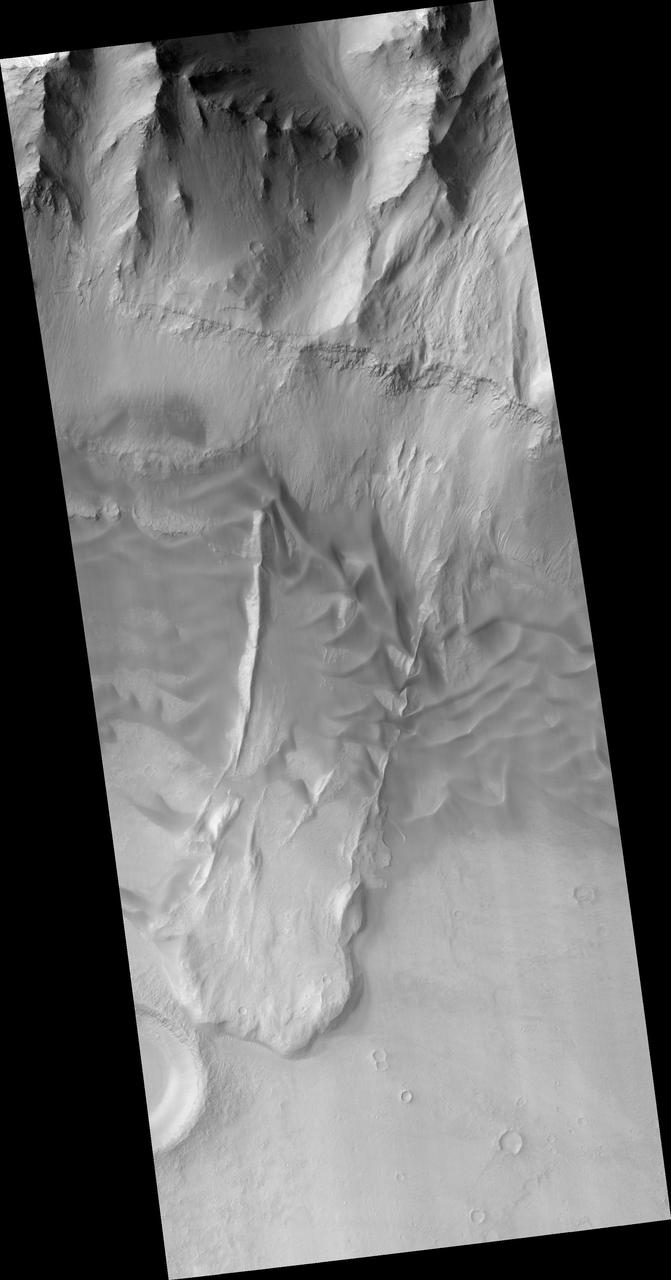
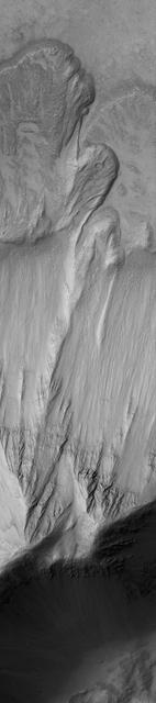
Rock Slide in Ophir
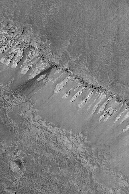
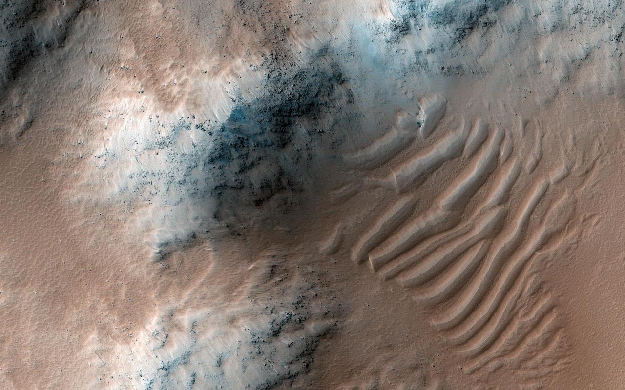
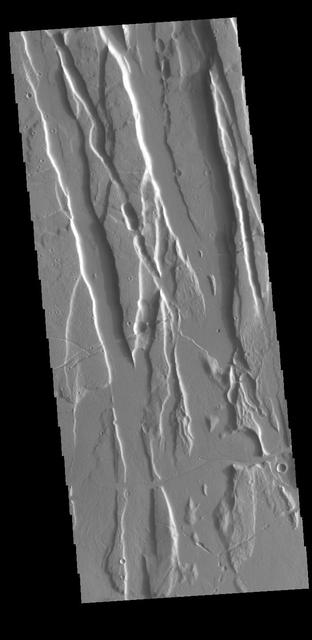
Slipping and Sliding in Coprates Chasma
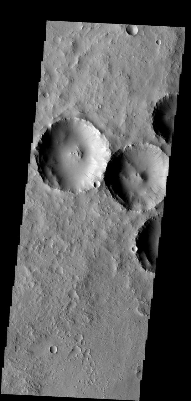
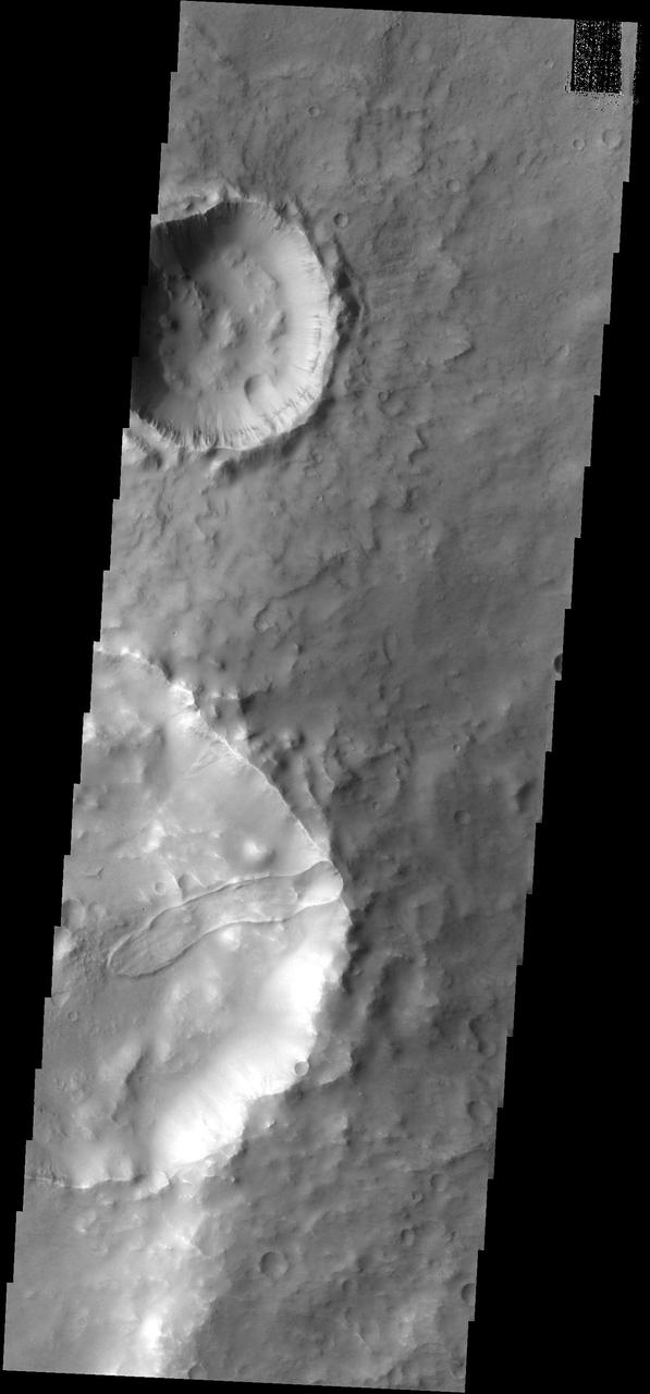
Dust slides occur within the larger craters in this image
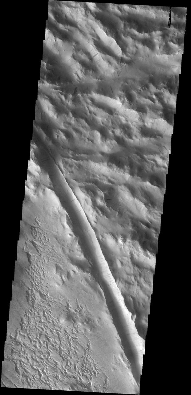
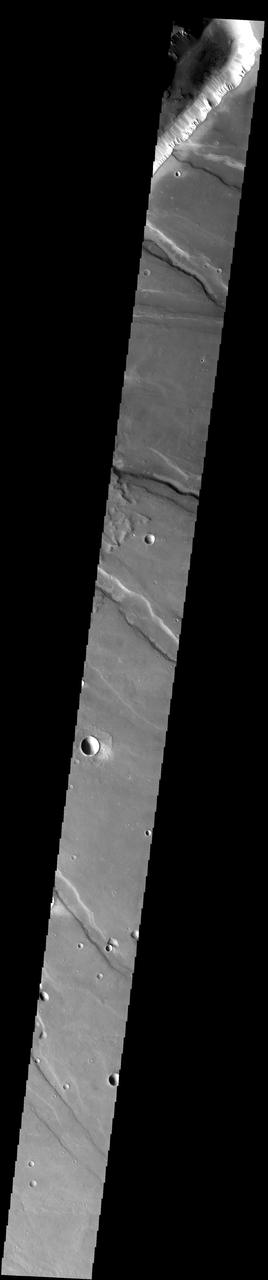
Dust slides are common in the dust covered region called Lycus Sulci. A large fracture is also visible in this image
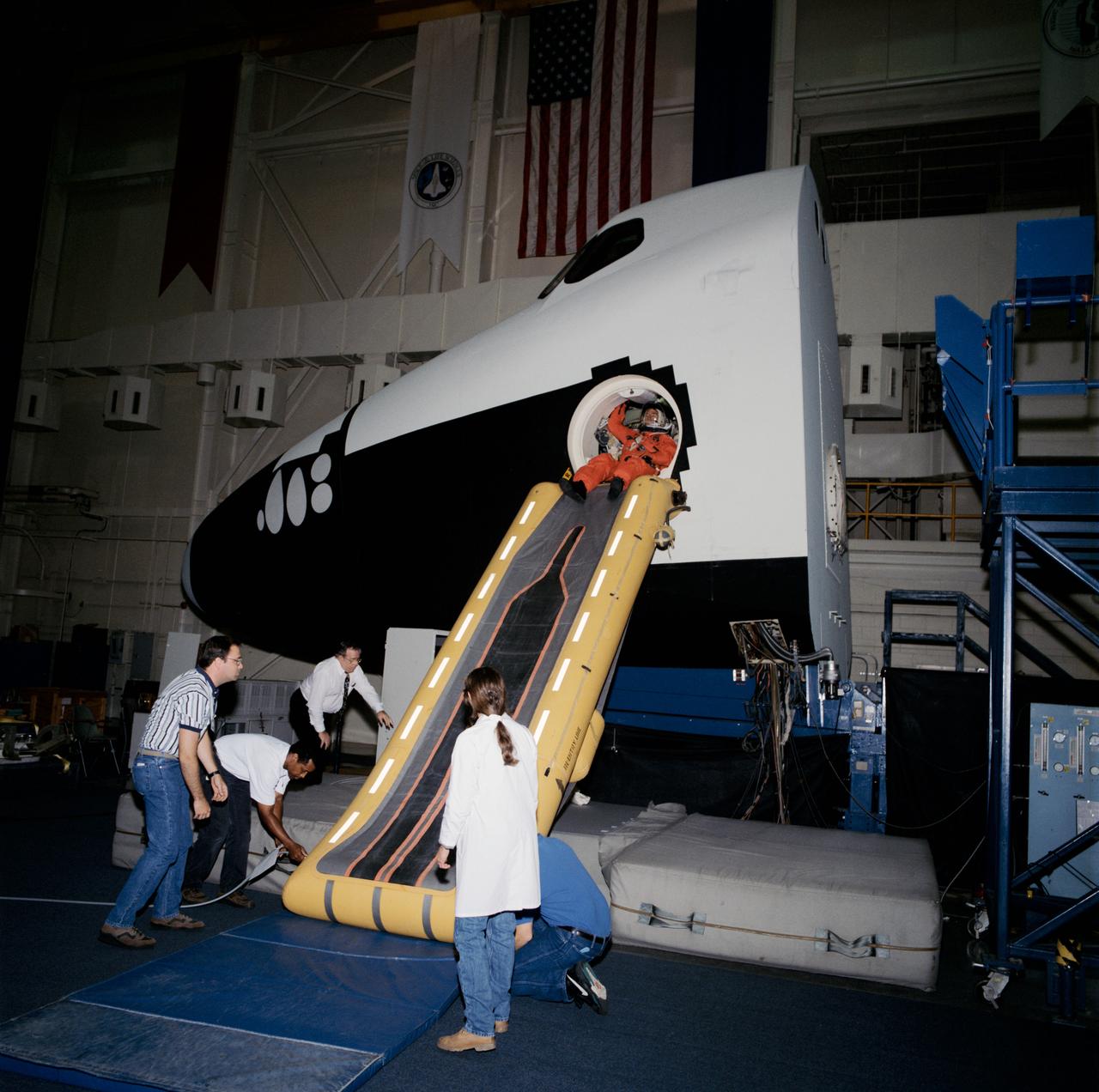
View of the STS-73 crew using the escape slide in the Crew Compartment Trainer (CCT) at bldg 9A. The crew is seen in their launch and entry suits at the top of the slide with trainers at the bottom.

These dust slides are located on the wall of Thithonium Chasma
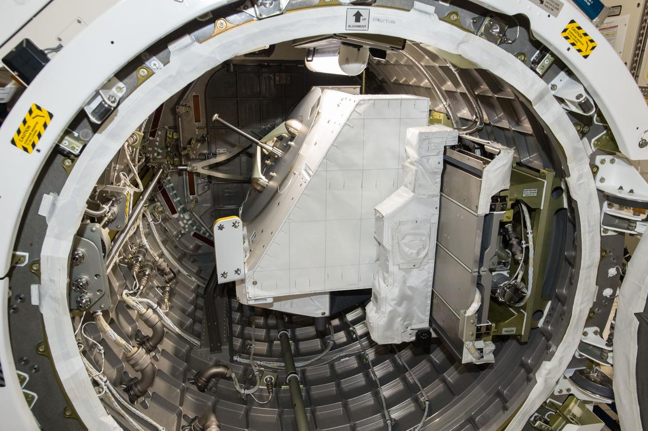
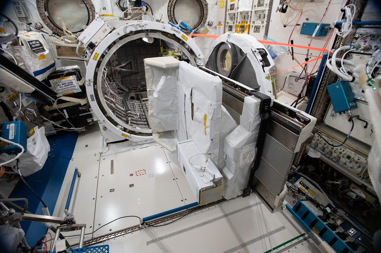
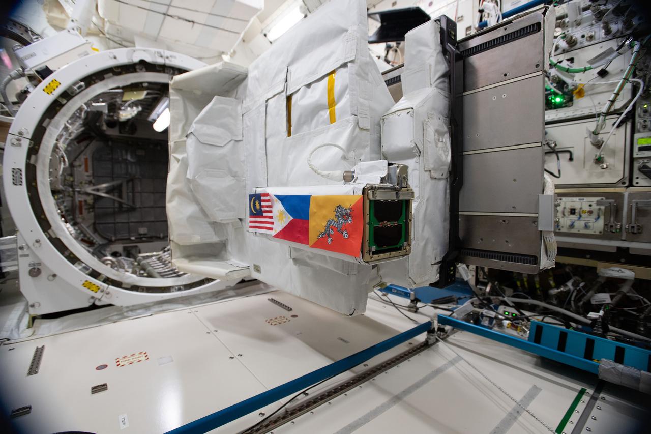
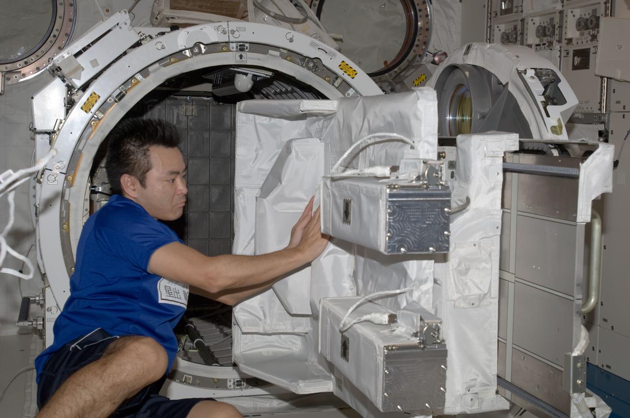
iss048e049218 (8/4/2016) --- Documentation of the NanoRacks External Platform (NREP) installed on the JEM (Japanese Experiment Module) Airlock (JEMAL) Slide Table (retracted into the JEMAL). Image was taken in the Kibo Japanese Experiment Pressurized Module (JPM). The NanoRacks External Platform is a compact research platform fitted for versatile use on the exterior of the International Space Station (ISS).
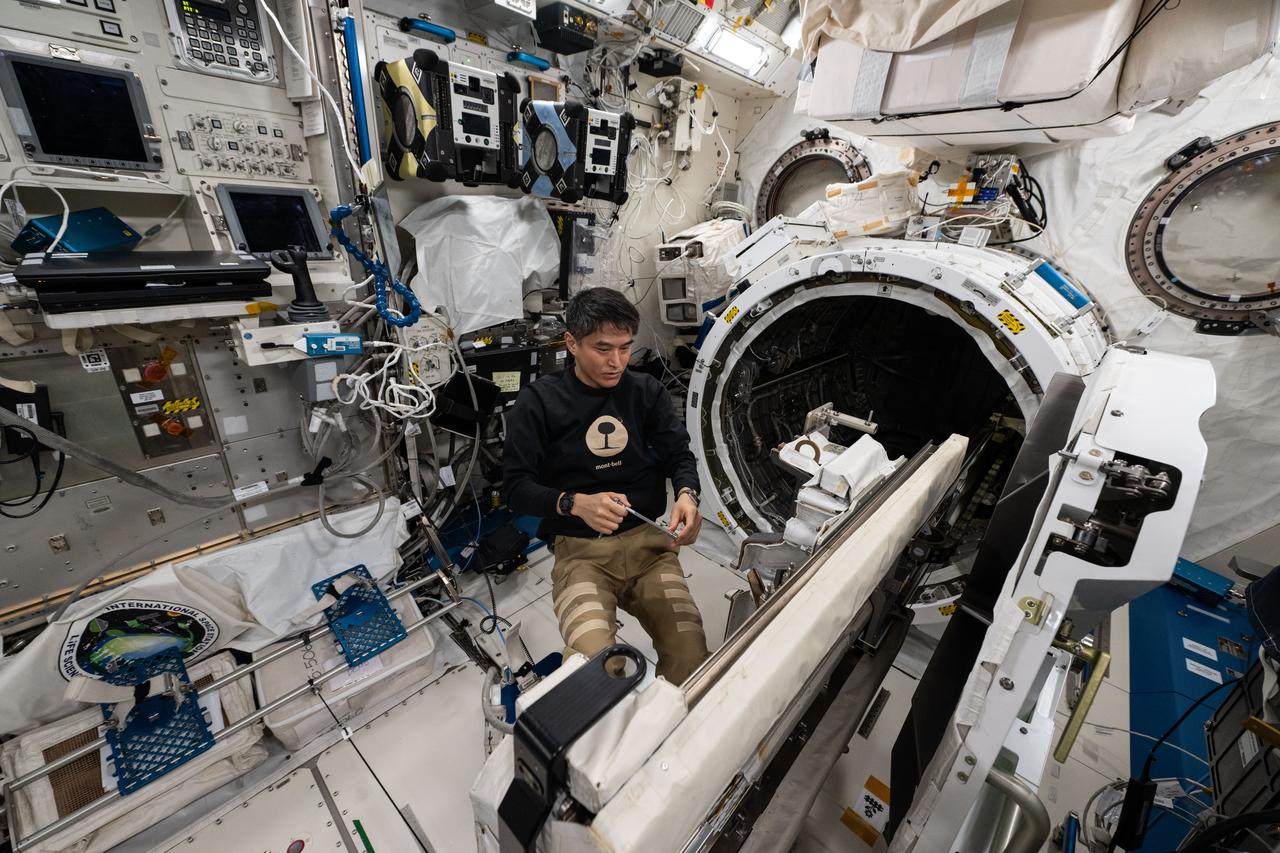
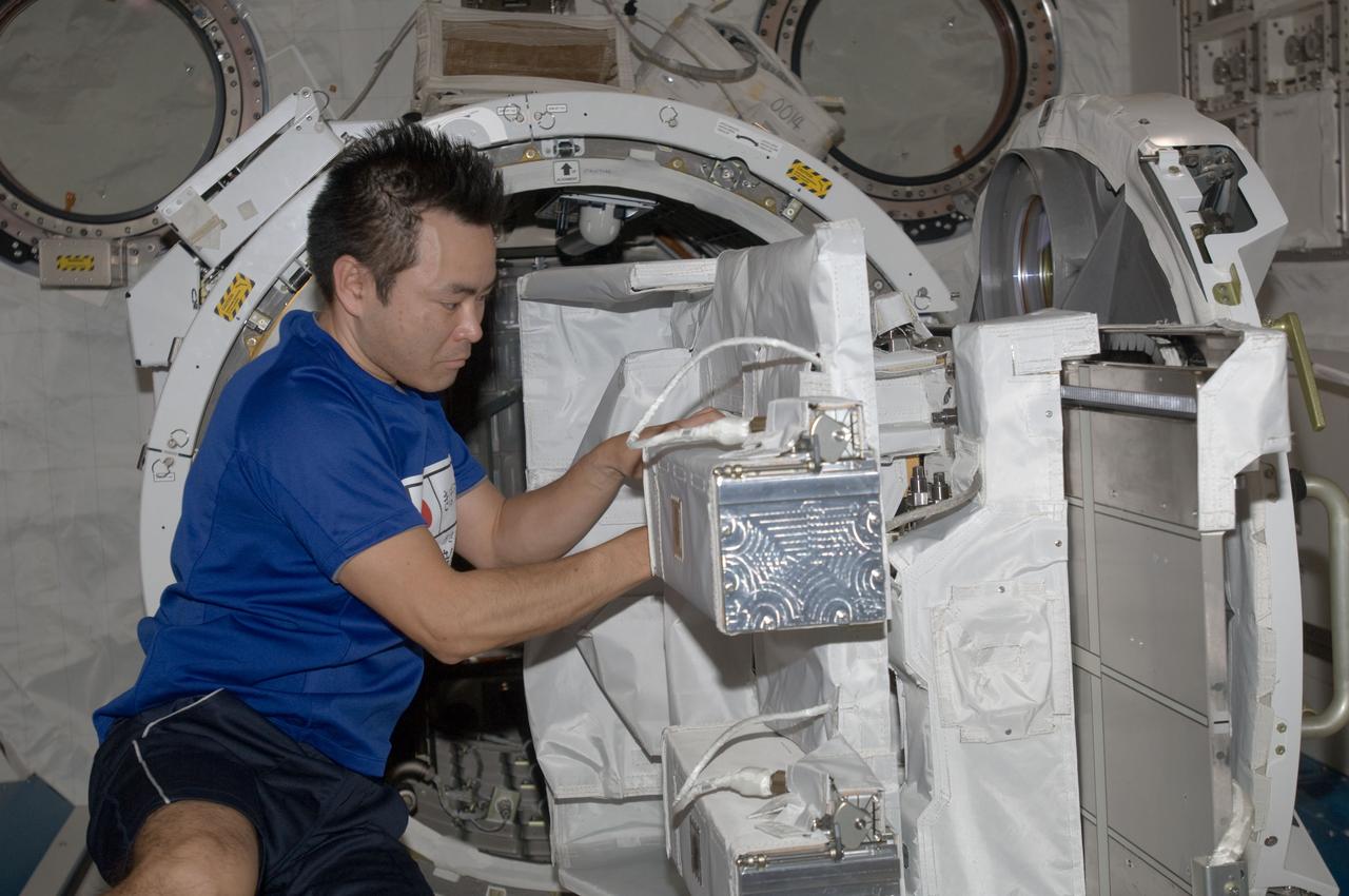
iss073e0383933 (July 4, 2025) --- JAXA (Japan Aerospace Exploration Agency) astronaut and Expedition 73 Commander Takuya Onishi removes research hardware attached to the Kibo laboratory module's airlock slide table aboard the International Space Station. The slide table can be retracted back and forth into the airlock where the Japanese robotic arm can grapple a variety of payloads and hardware for installation on the outside of Kibo for exposure to the external space environment.
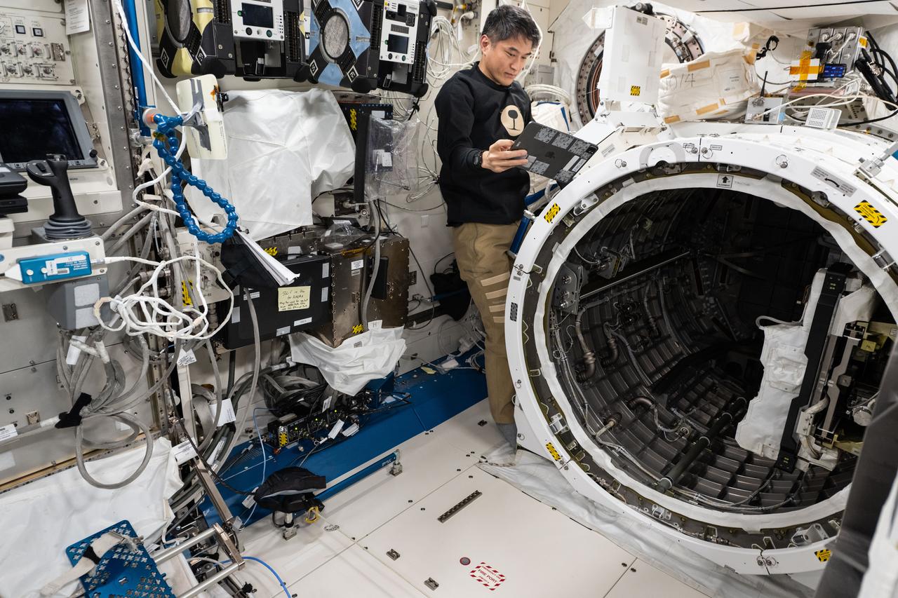
iss073e0383929 (July 4, 2025) --- JAXA (Japan Aerospace Exploration Agency) astronaut and Expedition 73 Commander Takuya Onishi prepares to retract a slide table that contains research hardware from inside the Kibo laboratory module's airlock. The slide table can be retracted back and forth into the airlock where the Japanese robotic arm can grapple a variety of payloads and hardware for installation on the outside of Kibo for exposure to the external space environment.
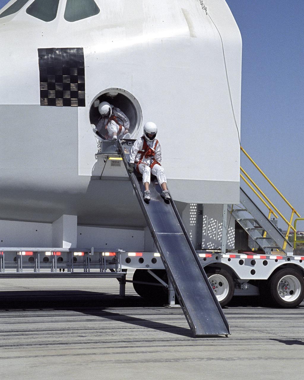
A volunteer "astronaut" starts down an exit slide from a Space Shuttle crew compartment mockup during a rescue and recovery training exercise.
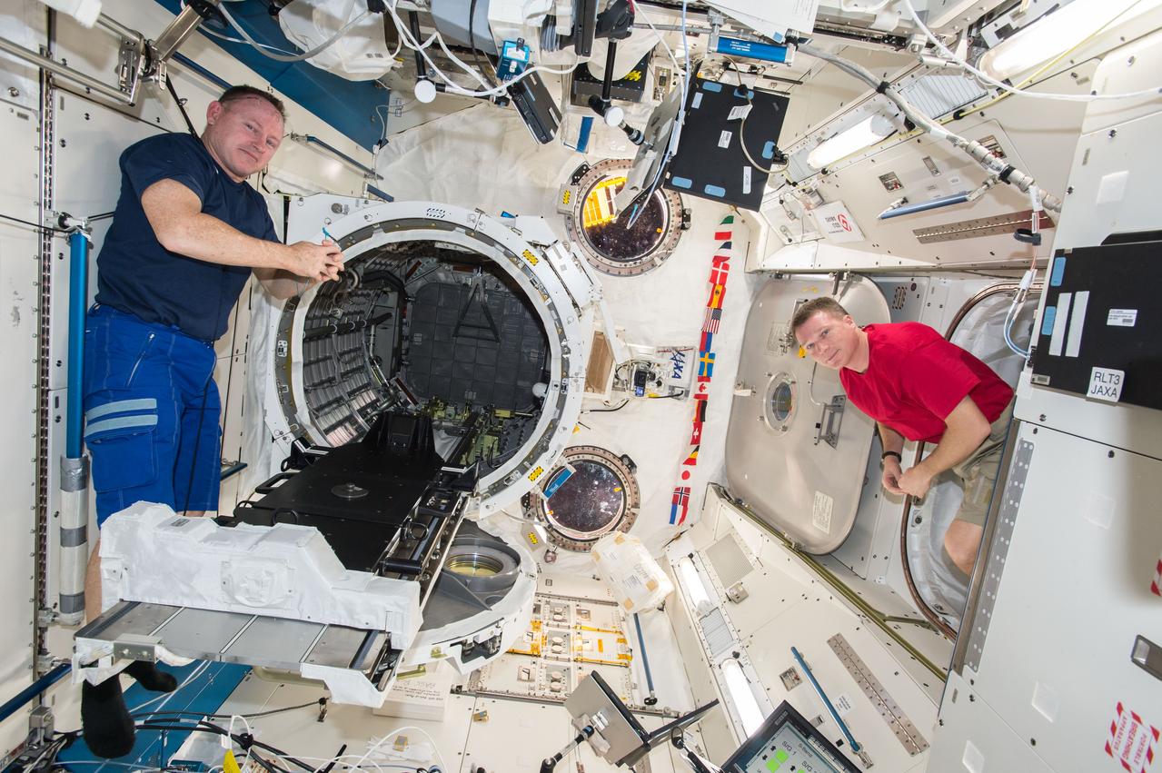
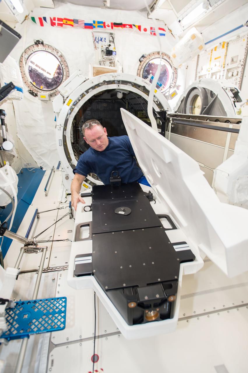
iss042e015971 (11/26/2011) --- NASA astronauts Barry Wilmore and Terry Virts are photographed during operations to install the Cyclops launch platform on the Japanese Experiment Module Airlock (JEMAL) slide table. The Cyclops platform, also known as the Space Station Integrated Kinetic Launcher for Orbital Payload Systems (SSIKLOPS), holds and ejects nanosatellites from outside the ISS.

The bright crescent of Saturn moon Enceladus slides past distant Rhea in this mutual event, or occultation, movie from Cassini
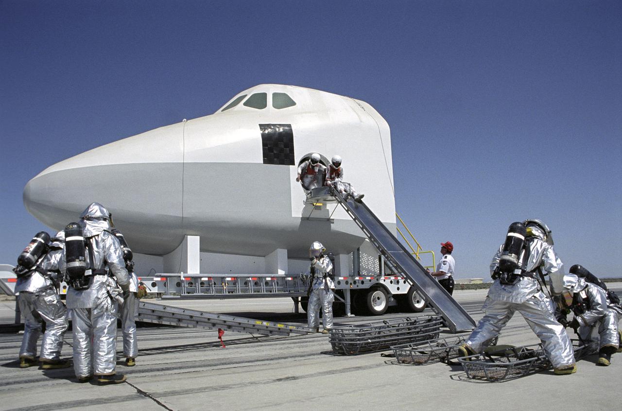
While fire-rescue personnel prepare evacuation litters, two stand-in "astronauts" prepare to use an exit slide from a Shuttle mockup during a rescue training exercise.
iss056e100542 (7/3/2018) --- A view of the Japanese Experiment Module (JEM) Airlock (AL) slide table retraction from Japanese Experiment Module (JPM) Side during JSSOD-9 operations. The JEM Small Satellite Orbital Deployer (J-SSOD) provides a novel, safe, small satellite launching capability to the International Space Station (ISS). Once the J-SSOD including satellite install cases with small satellites are installed on the Multi-Purpose Experiment Platform (MPEP) by crewmembers, it is passed through the JEM airlock for retrieval, positioning and deployment by the JEMRMS.
iss056e100586 (7/30/2018) --- A view of the Japanese Experiment Module (JEM) Airlock (AL) slide table retraction from Japanese Experiment Module (JPM) during JSSOD-9 operations. The JEM Small Satellite Orbital Deployer (J-SSOD) provides a novel, safe, small satellite launching capability to the International Space Station (ISS). Once the J-SSOD including satellite install cases with small satellites are installed on the Multi-Purpose Experiment Platform (MPEP) by crewmembers, it is passed through the JEM airlock for retrieval, positioning and deployment by the JEMRMS.
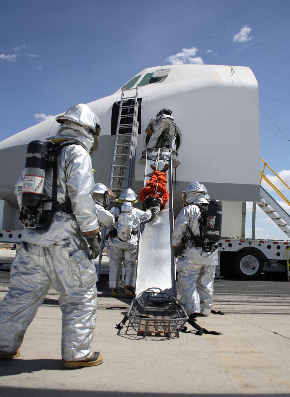
Clad in thermal protection suits, fire/rescue crew aid a volunteer "Injured astronaut" to a head-first ride down the exit slide from the shuttle cabin mockup. (USAF photo # 070505-F-1287F-132)
This landslide occurs in an unnamed crater
These dust avalanches occur in a crater within Iani Chaos
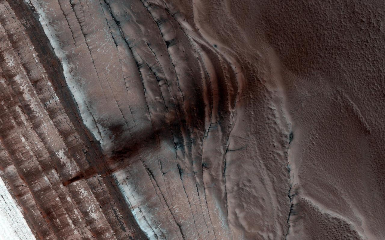
The North Polar region of Mars is capped with layers of water ice and dust, called the polar layered deposits. This permanent polar cap is covered in the winter with a layer of seasonal carbon dioxide ice as seen by NASA Mars Reconnaissance Orbiter.
The dunes and landslides in this image occur within Coprates Chasma
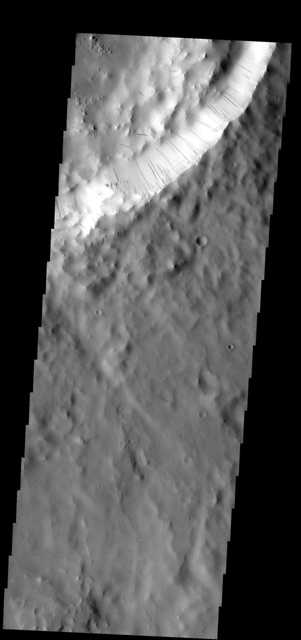
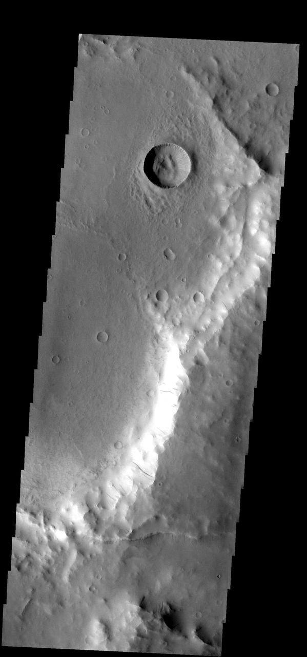
These dark streaks show where dust has been moving down the rim of the unnamed crater
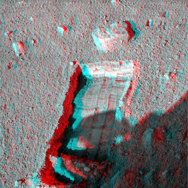
The robotic arm on NASA Phoenix Mars Lander enlarged a trench beside a rock called Headless on Sept. 20, 2008 in preparation for sliding the rock into the trench. 3D glasses are necessary to view this image.
This MOC image shows some dark slope streaks in the Phlegra Dorsa region of Mars. Of particular interest is the split streak near the center of the image, which diverted around a rounded hill as the material was sliding down the slope
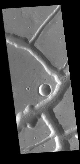
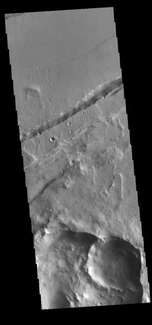
The channel feature in this image from NASA 2001 Mars Odyssey spacecraft is called Mangala Fossa. This feature was formed by tectonic activity, with the walls being faults that allowed the central portion to slide downward forming a graben.
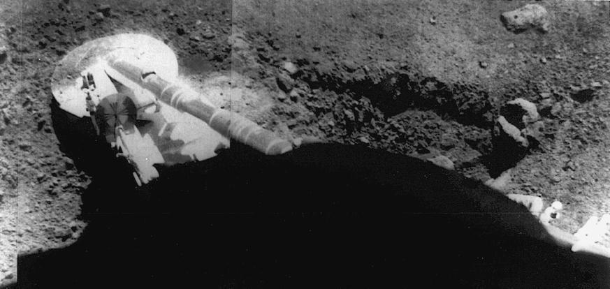
Surveyor 5 image of the footpad resting in the lunar soil. The trench at right was formed by the footpad sliding during landing. Surveyor 5 landed on the Moon on 11 September 1967 at 1.41 N, 23.18E in Mare Tranquillitatis.
Most of the hills in this image from NASA 2001 Mars Odyssey spacecraft have dark streaks thought to be where bright dust has been removed by sliding down the hillside.

Stately Saturn sits surrounded by its darkened disk of ice. An increasing range of hues has become visible in the northern hemisphere as spring approaches and the ring shadows slide southward
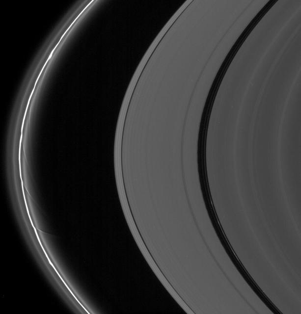
The A and F rings are alive with moving structures in this Cassini spacecraft view. Graceful drapes of ring material created by Prometheus are seen sliding by at left, while clumpy ringlets slip through the Encke Gap
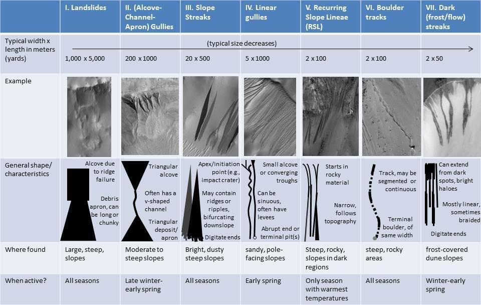
As on the Earth, many processes can move material down a Martian slope. This graphic compares seven different types of features observed on Mars that appear to result from material flowing or sliding or rolling down slopes.
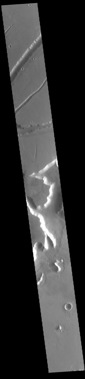
Coprates Chasma comprises the central portion of the Valles Marineris canyon system complex. This image from NASA Mars Odyssey spacecraft of the southern wall of Coprates Chasma contains a landslide deposit with dunes over portions of slide.
This VIS image shows a section of Sirenum Fossae. The linear features are called graben. Graben are formed by blocks of material sliding downward between pairs of faults. Orbit Number: 74365 Latitude: -28.1401 Longitude: 215.795 Instrument: VIS Captured: 2018-09-19 11:11 https://photojournal.jpl.nasa.gov/catalog/PIA22802
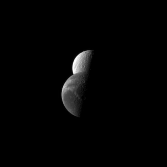
Saturn moon Dione passes by the moon Tethys in this NASA Cassini spacecraft depiction of a mutual event in which one moon passes close to or in front of another moon.
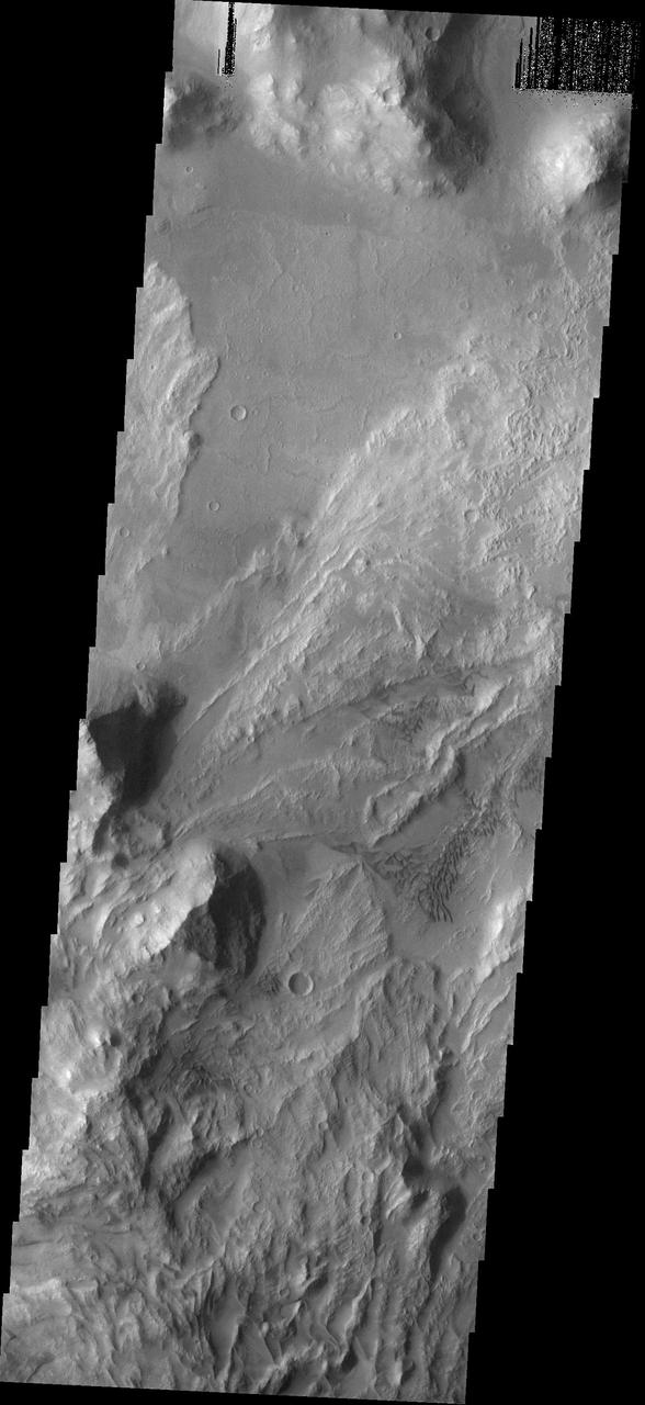
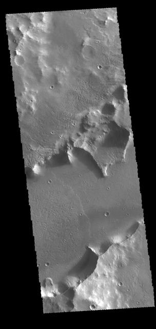
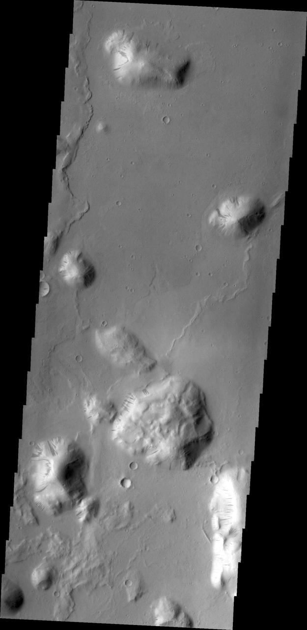
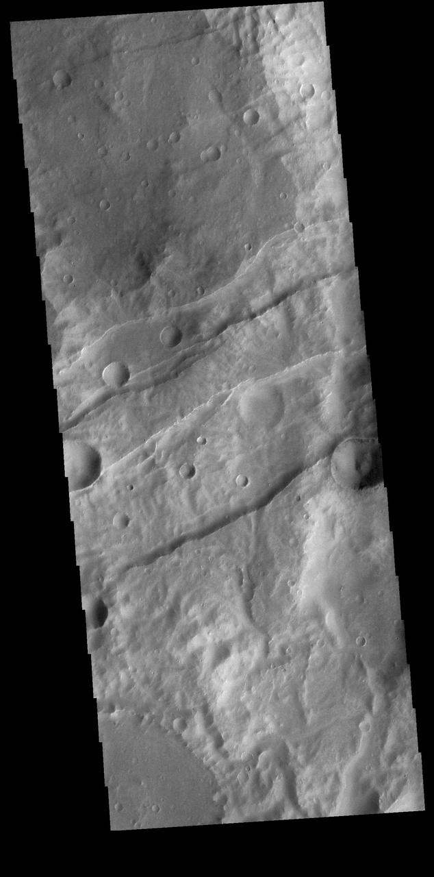
Echus Chaos is a region of low hills located between Lunae Planum (to the right of this image) and Echus Palus (to the left of this image). This chaos terrain may have formed as the rocks that make up Lunae Planum slowly slid downhill into Echus Palus. As these rocks slid downhill, they broke up into large pieces that formed the hills that we see today. What caused this landslide is not well known, but it could have been due to large floods of water moving through Echus Palus, causing the edge of Lunae Planum to become soaked and fall apart. Ground shaking from movement along nearby faults or meteorite impacts may have also helped to make the edge of Lunae Planum unstable and collapse. https://photojournal.jpl.nasa.gov/catalog/PIA25556
The slope streaks and small, dark landslides are located in Noctus Labyrinthus
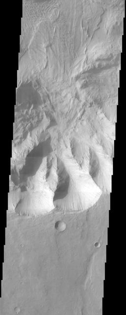
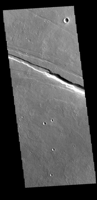
This MOC image shows a landslide that occurred off of a steep slope in Tithonium Chasma, part of the vast Valles Marineris trough system

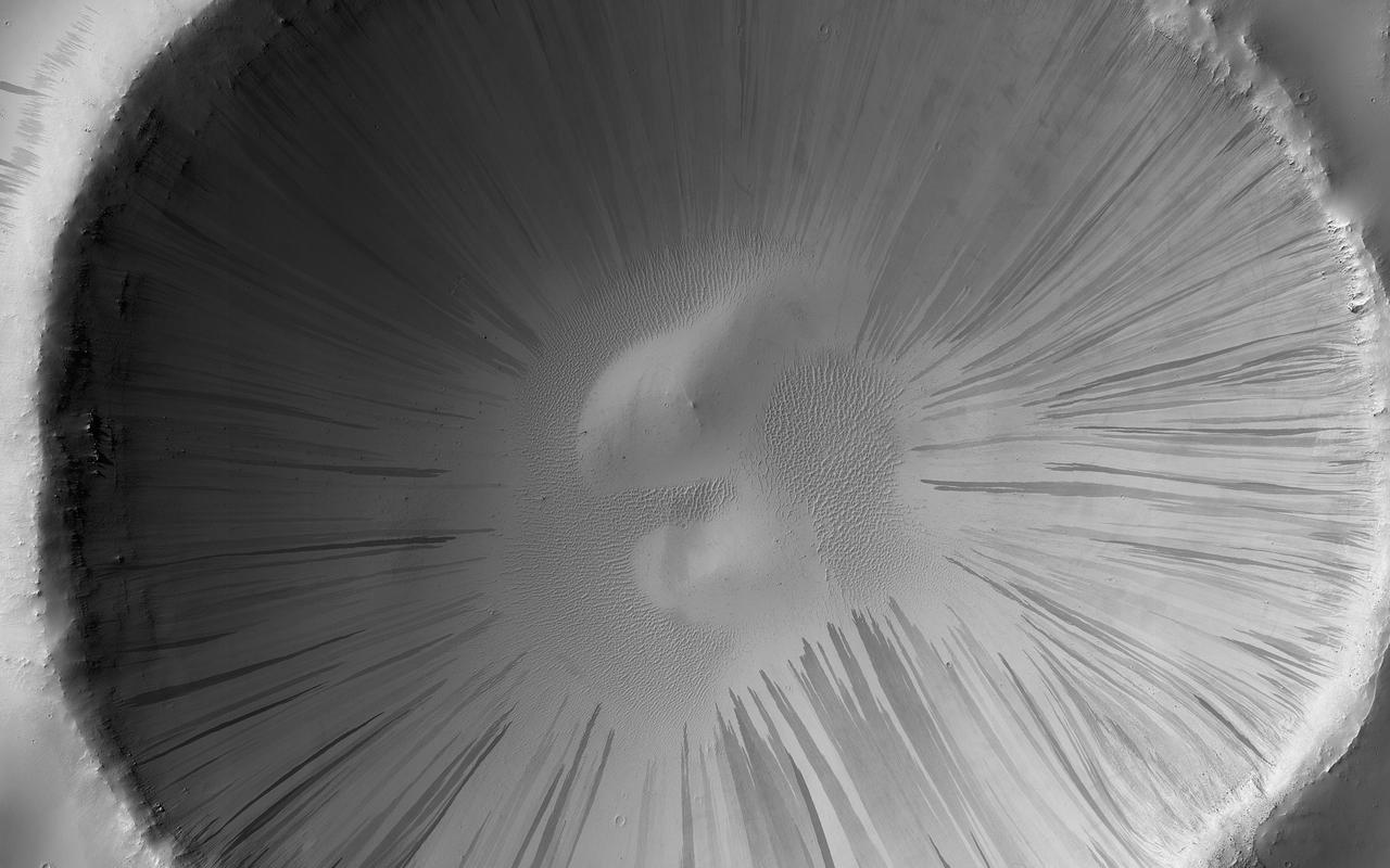
This image was obtained by NASA's Dawn spacecraft on June, 16 2018 from an altitude of about 24 miles (39 kilometers). NASA announced the conclusion of Dawn's mission operations was Oct. 31, 2018, when the spacecraft depleted its hydrazine. The center of this feature is located at about 16.1 degrees north latitude and 242.8 degrees east longitude. https://photojournal.jpl.nasa.gov/catalog/PIA22982
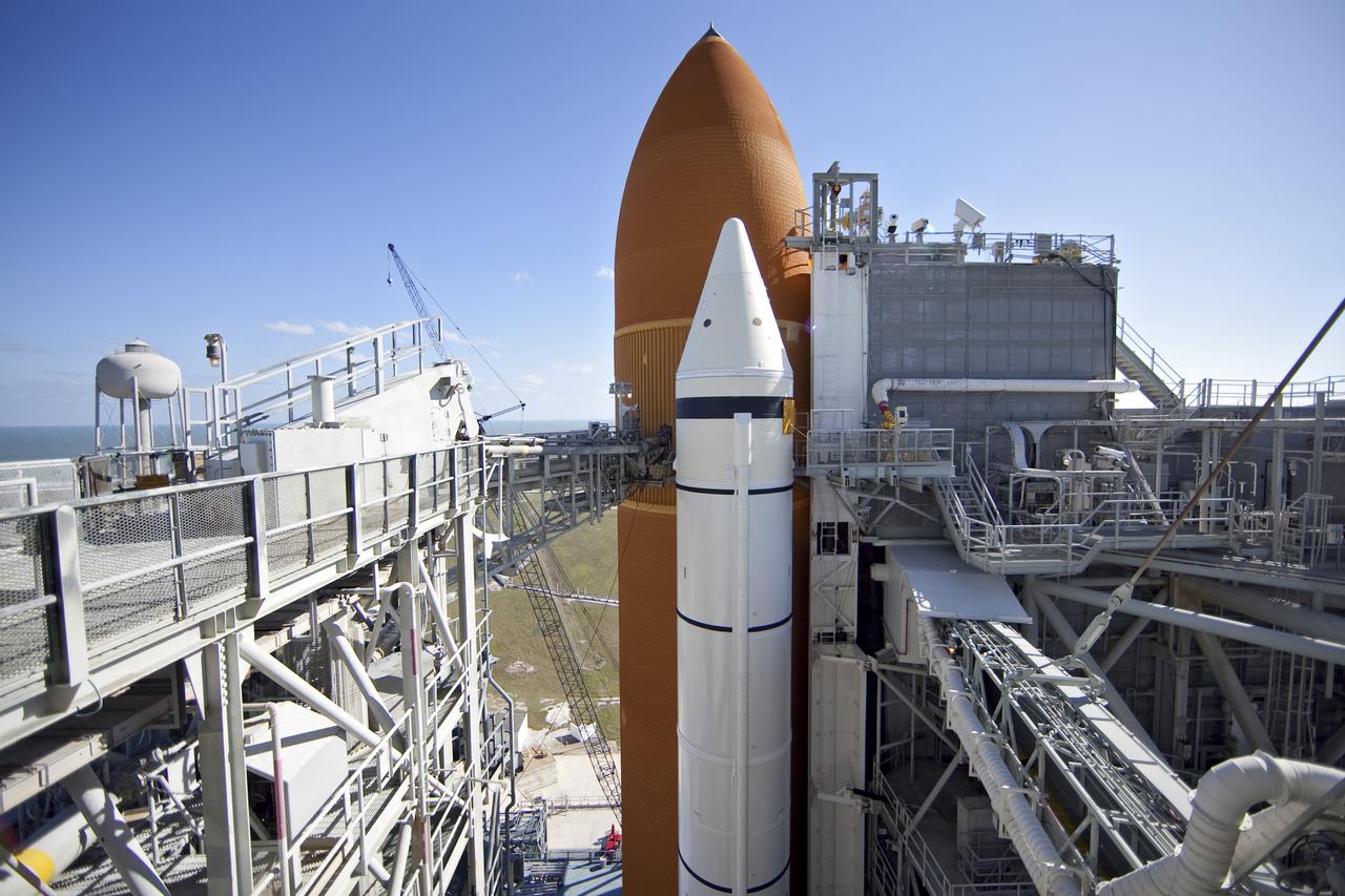
STS-133 DISCOVERY ET-137 X-RAY BACK SCATTER & SLIDE BASKET
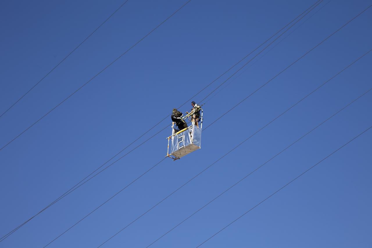
STS-133 DISCOVERY ET-137 X-RAY BACK SCATTER & SLIDE BASKET
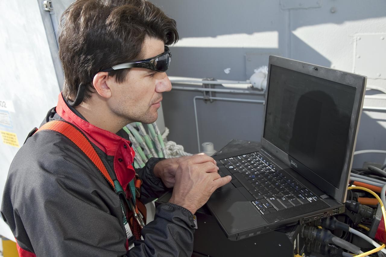
STS-133 DISCOVERY ET-137 X-RAY BACK SCATTER & SLIDE BASKET
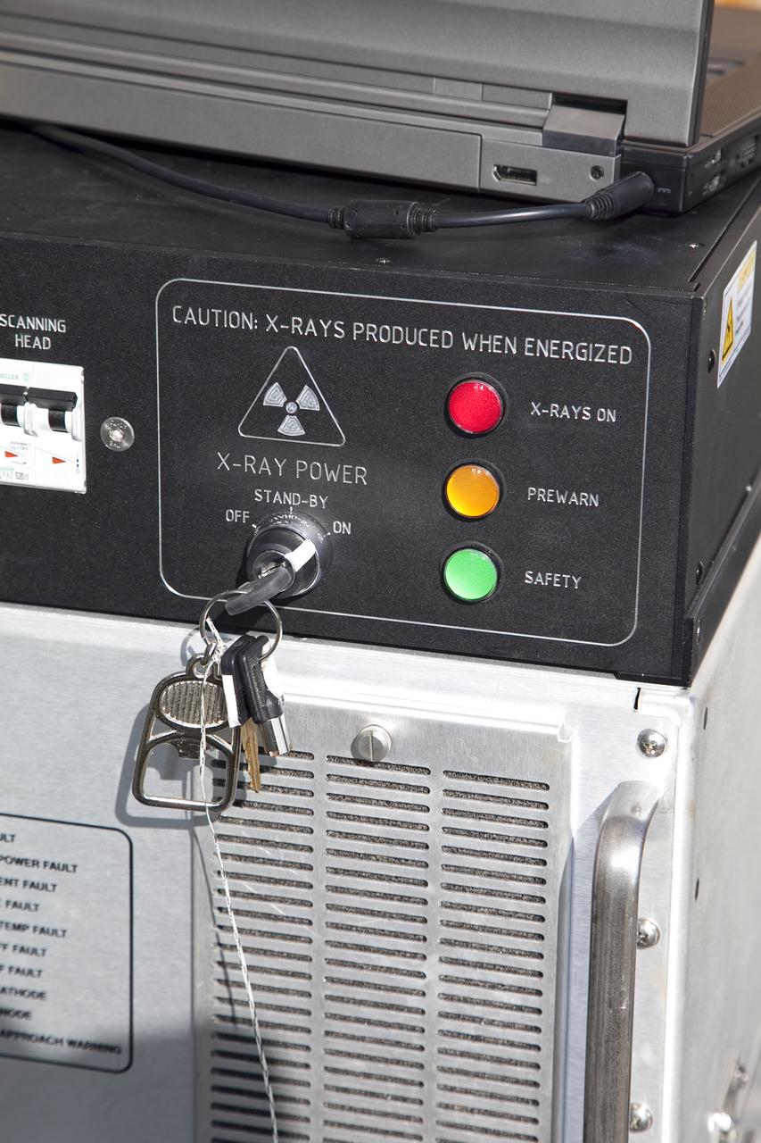
STS-133 DISCOVERY ET-137 X-RAY BACK SCATTER & SLIDE BASKET
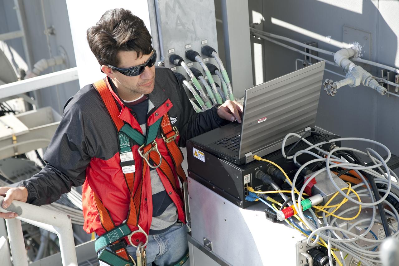
STS-133 DISCOVERY ET-137 X-RAY BACK SCATTER & SLIDE BASKET
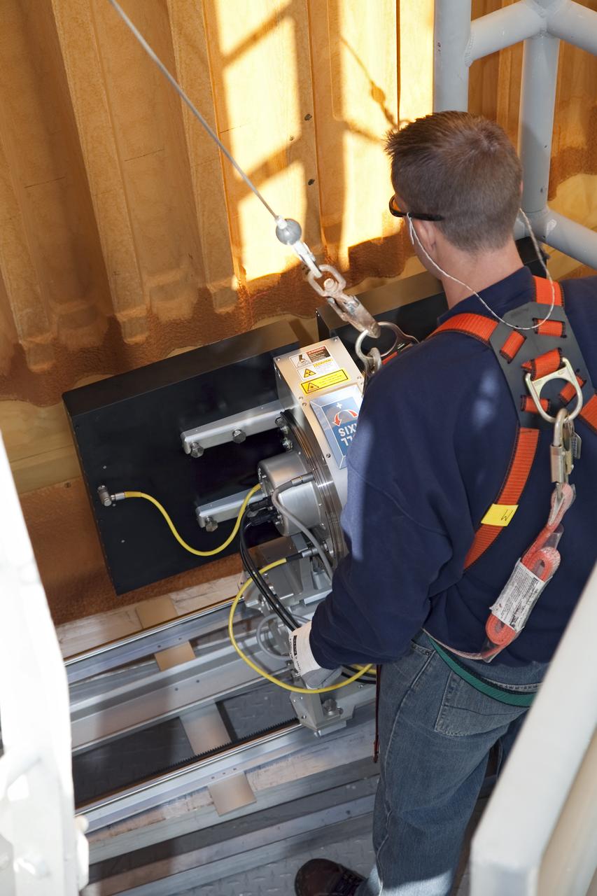
STS-133 DISCOVERY ET-137 X-RAY BACK SCATTER & SLIDE BASKET
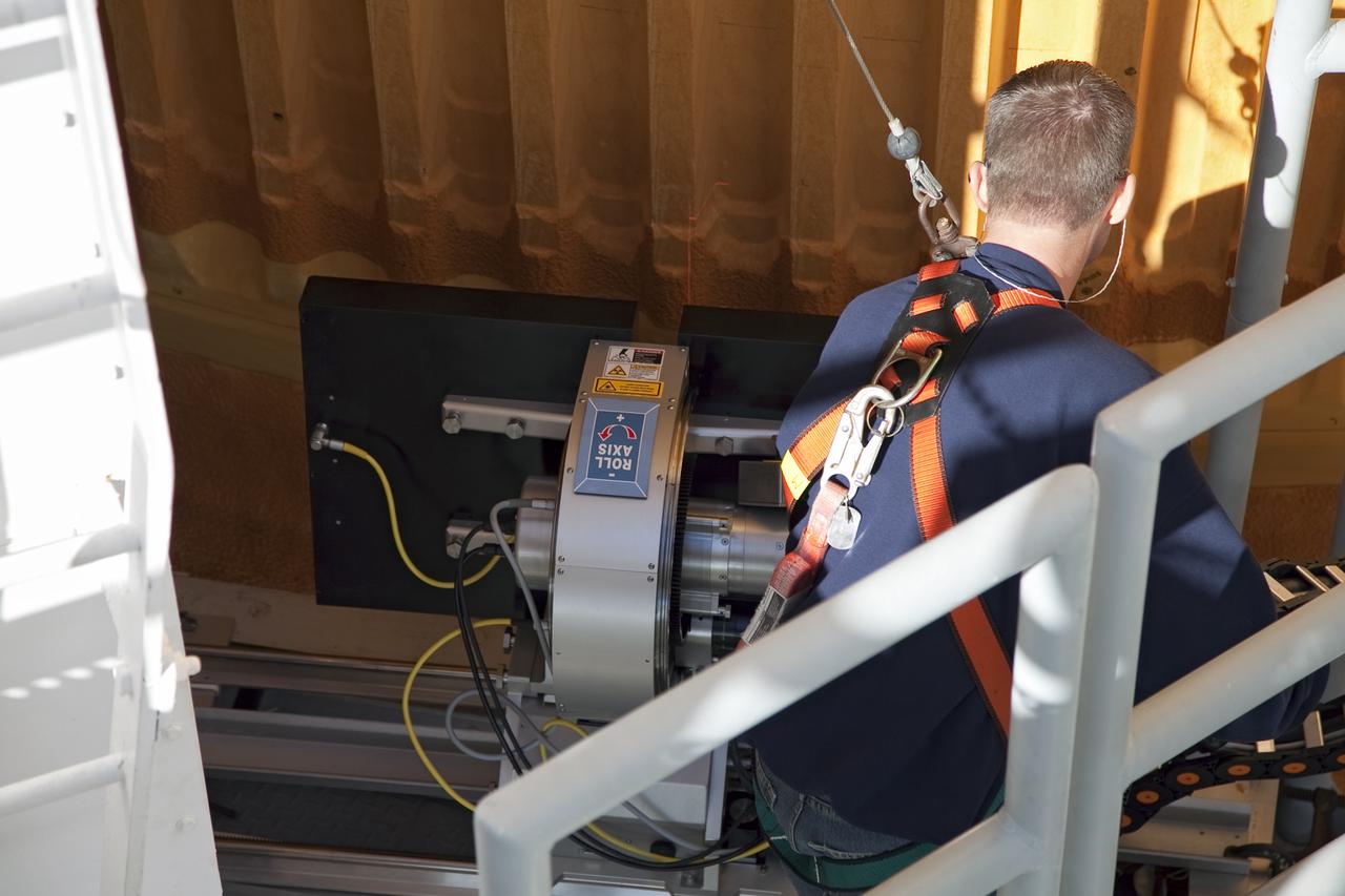
STS-133 DISCOVERY ET-137 X-RAY BACK SCATTER & SLIDE BASKET
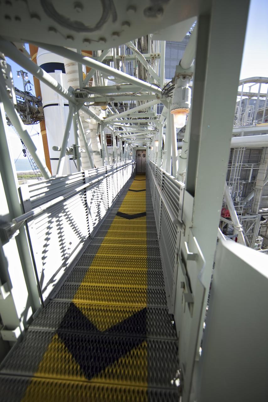
STS-133 DISCOVERY ET-137 X-RAY BACK SCATTER & SLIDE BASKET
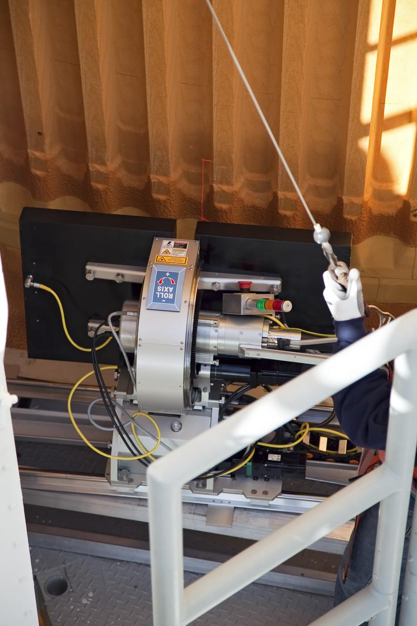
STS-133 DISCOVERY ET-137 X-RAY BACK SCATTER & SLIDE BASKET
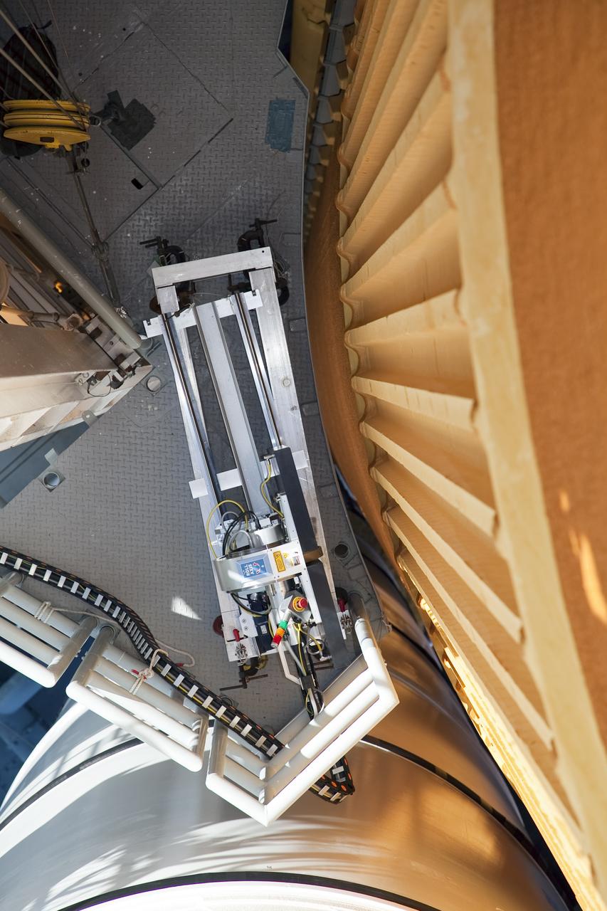
STS-133 DISCOVERY ET-137 X-RAY BACK SCATTER & SLIDE BASKET
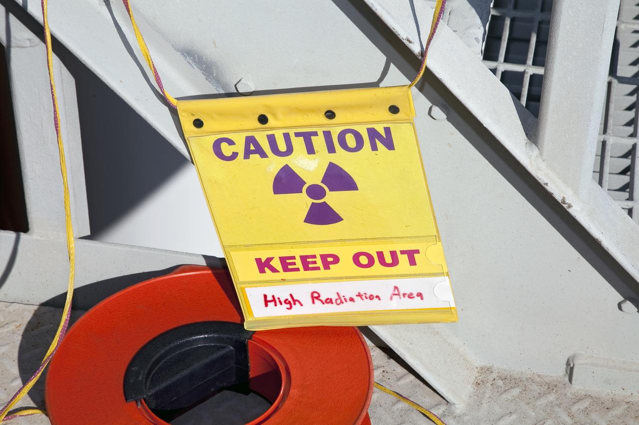
STS-133 DISCOVERY ET-137 X-RAY BACK SCATTER & SLIDE BASKET
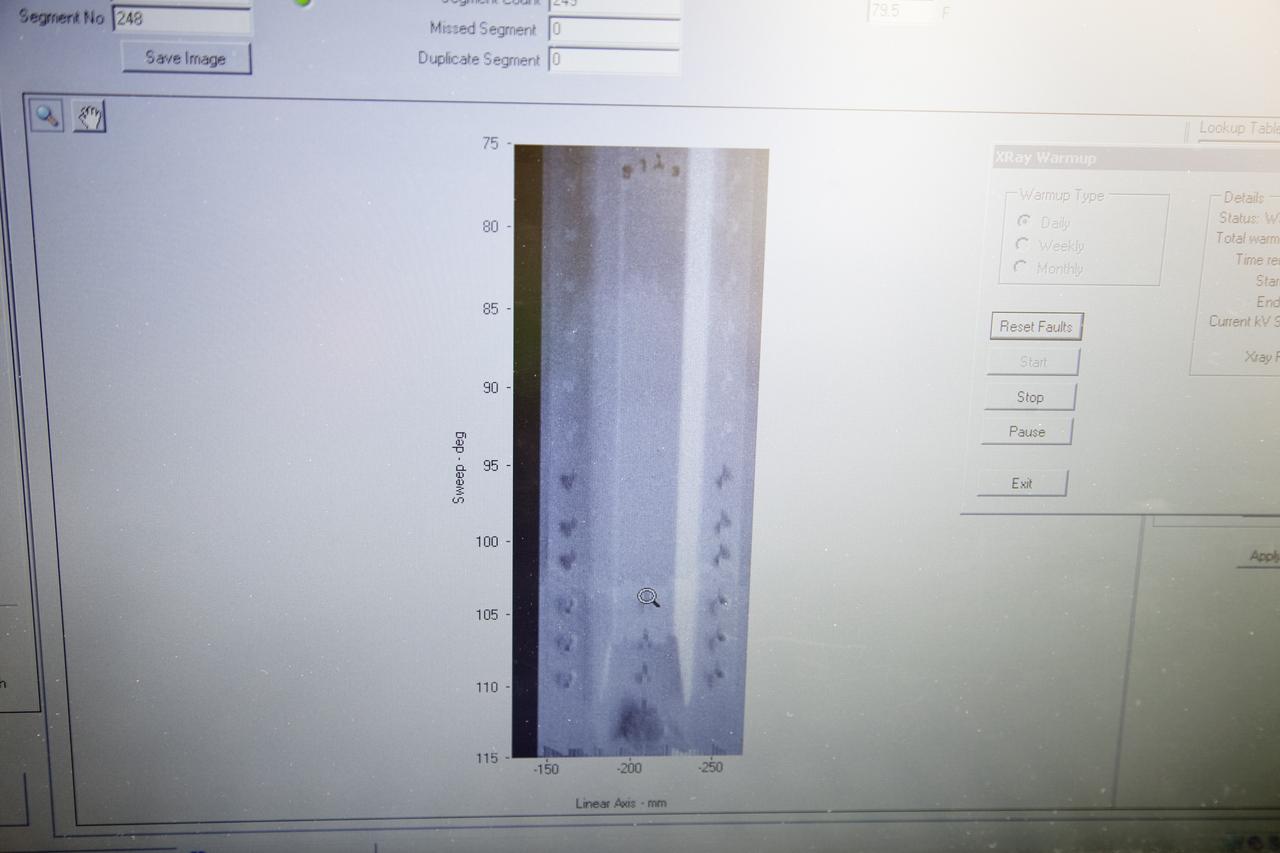
STS-133 DISCOVERY ET-137 X-RAY BACK SCATTER & SLIDE BASKET
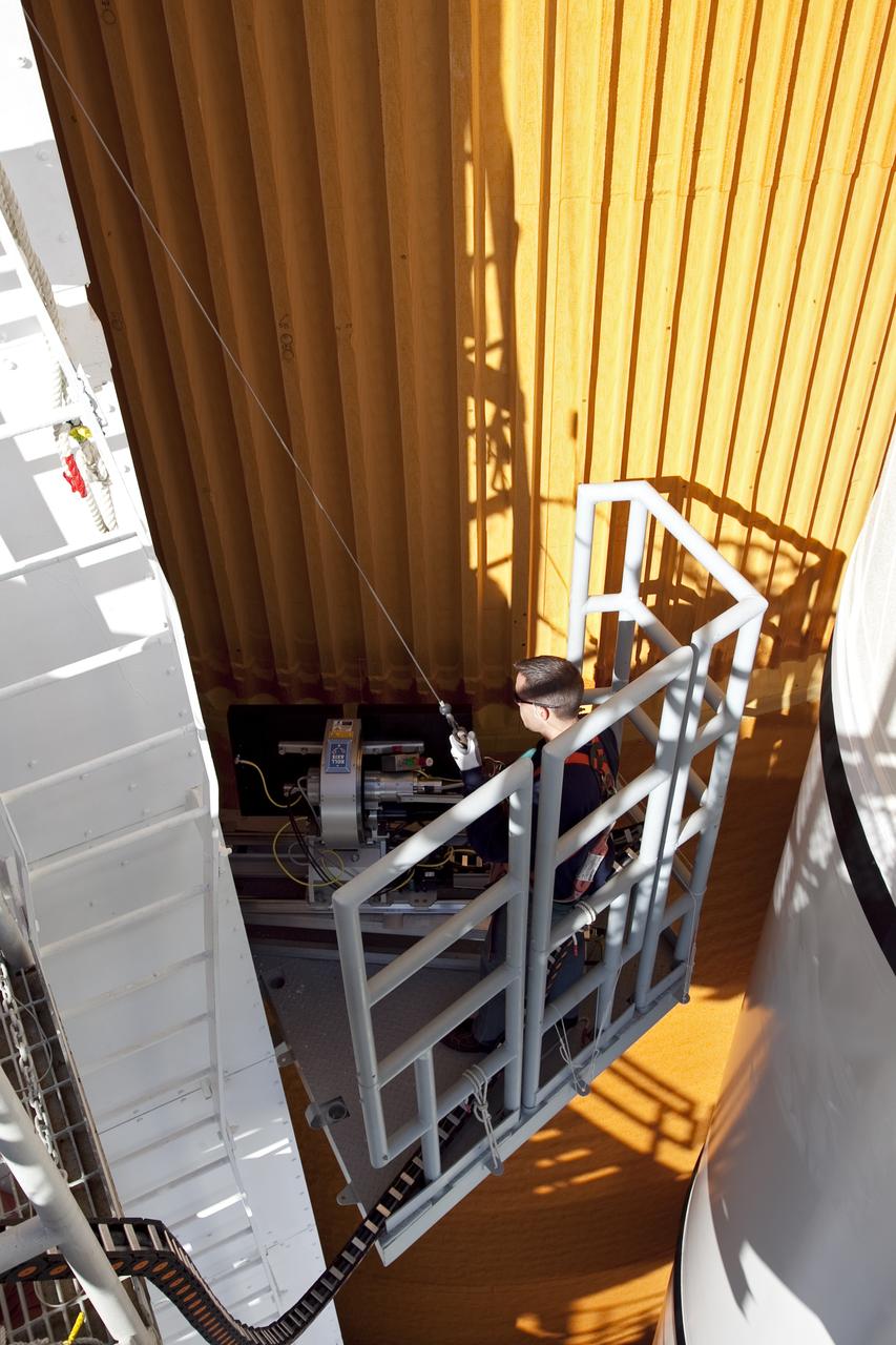
STS-133 DISCOVERY ET-137 X-RAY BACK SCATTER & SLIDE BASKET
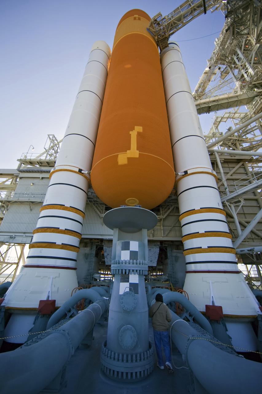
STS-133 DISCOVERY ET-137 X-RAY BACK SCATTER & SLIDE BASKET
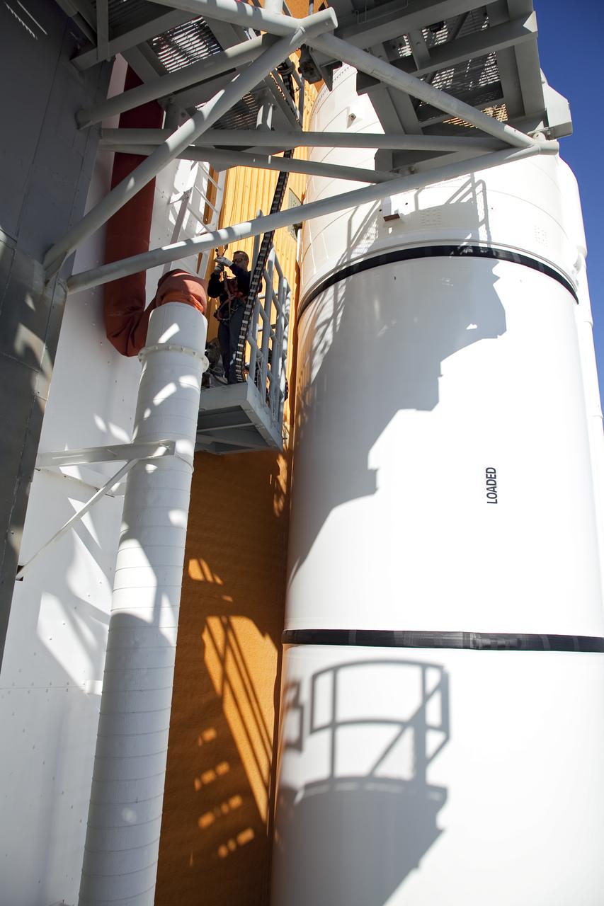
STS-133 DISCOVERY ET-137 X-RAY BACK SCATTER & SLIDE BASKET
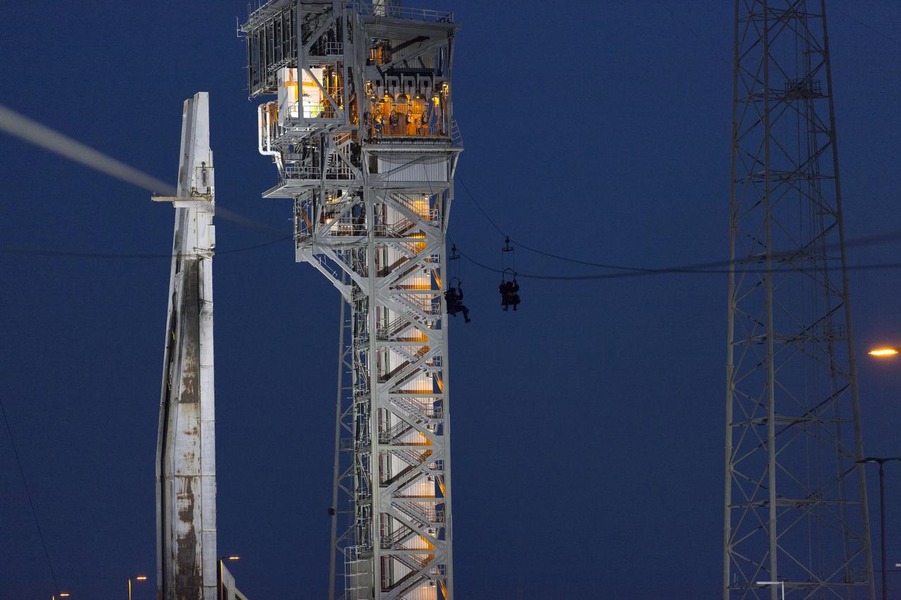
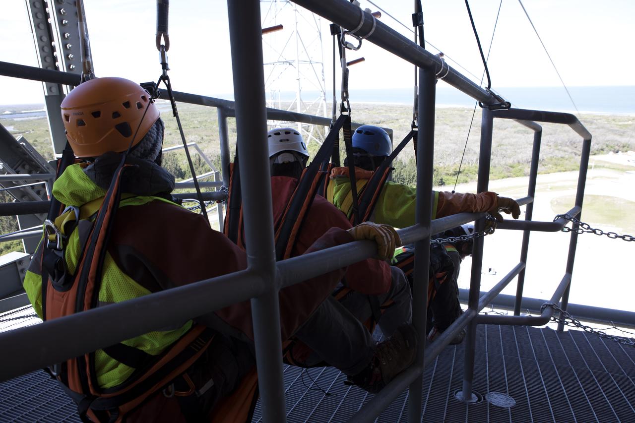
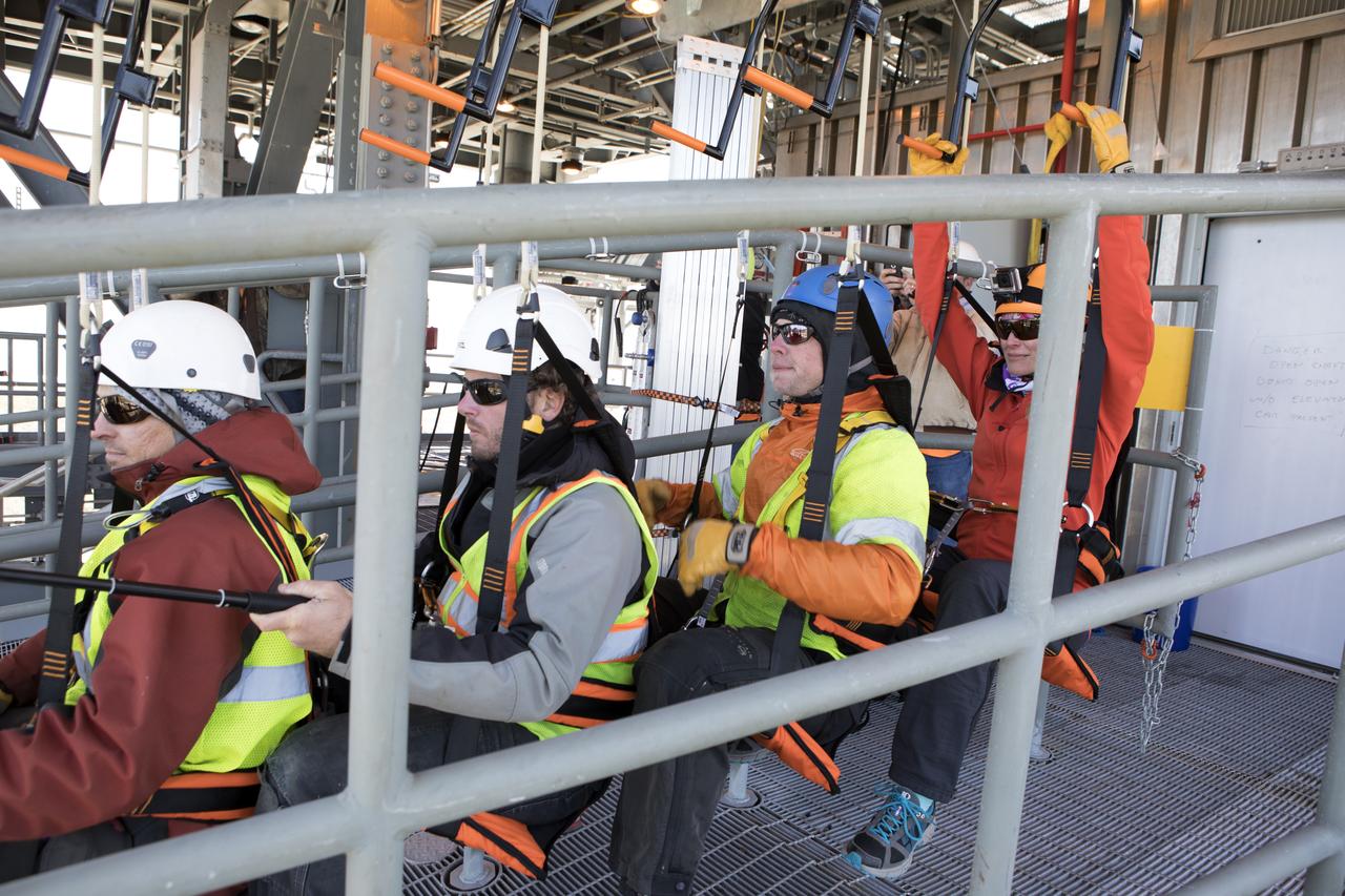
Commercial Crew astronauts participate in a Boeing/United Launch Alliance (ULA) emergency egress system demonstration at Cape Canaveral Air Force Station’s Launch Complex 41 in Florida on June 19, 2018. The emergency egress system features folding seats attached to slide wires. In the unlikely event of an emergency prior to liftoff on launch day, each person on the Crew Access Tower would get his or her own seat and slide more than 1,300 feet to a safe area.

ISS045e147255 (11/28/2015) --- Nightfall slides across the Earth and astronauts & cosmonauts aboard the International Space Station begin their resting period after many hours of conducting experiments and maintaining the station.
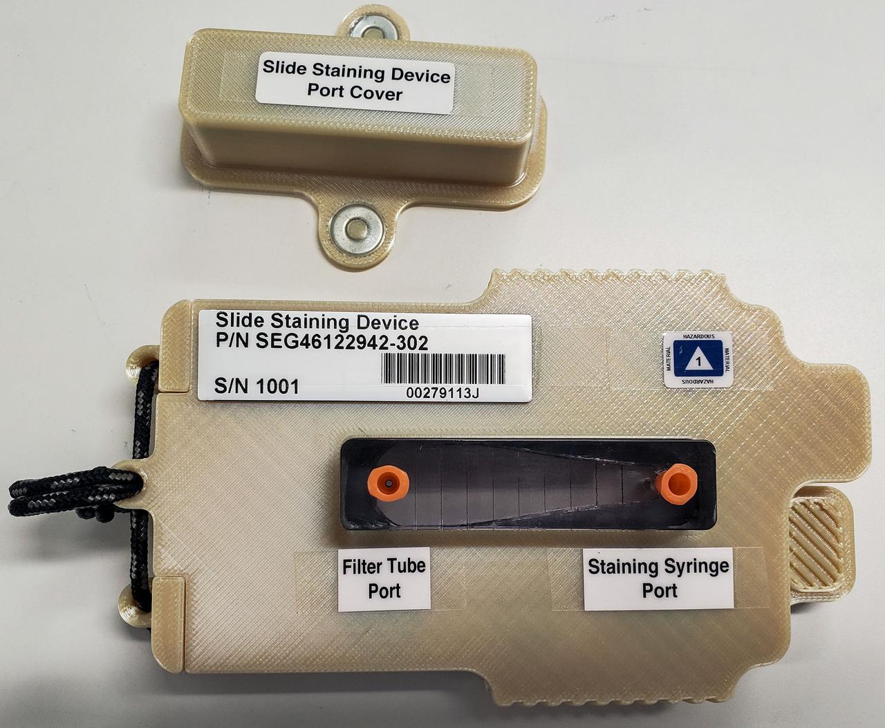
jsc2022e083575 (10/4/2022) --- A preflight image of the slide staining device developed for the Moon Microscope investigation. Image courtesy of NASA’s Johnson Space Center Immunology/Virology Laboratory.
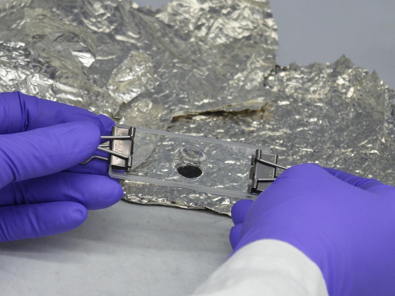
A portion of the asteroid Bennu sample delivered to Earth by NASA's OSIRIS-REx (Origins, Spectral Interpretation, Resource Identification, and Security – Regolith Explorer) mission, set into a microscope slide at the agency's Goddard Space Flight Center in Greenbelt, Maryland.
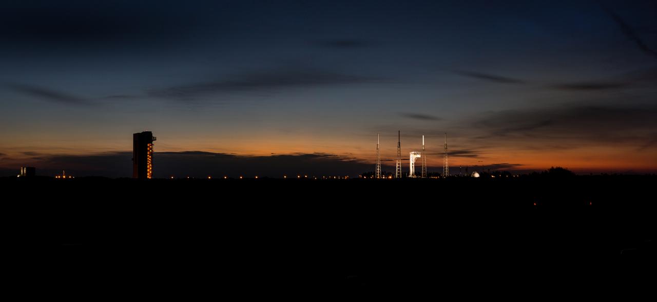
The sun sets on Cape Canaveral Air Force Station’s Launch Complex 41 in Florida during a Boeing/United Launch Alliance (ULA) emergency egress system demonstration on June 19, 2018. The emergency egress system features folding seats attached to slide wires. In the unlikely event of an emergency on launch day prior to liftoff, each person on the Crew Access Tower would get his or her own seat and slide more than 1,300 feet to a safe area. The Boeing CST-100 Starliner will launch on a ULA Atlas V rocket, carrying astronauts to the International Space Station
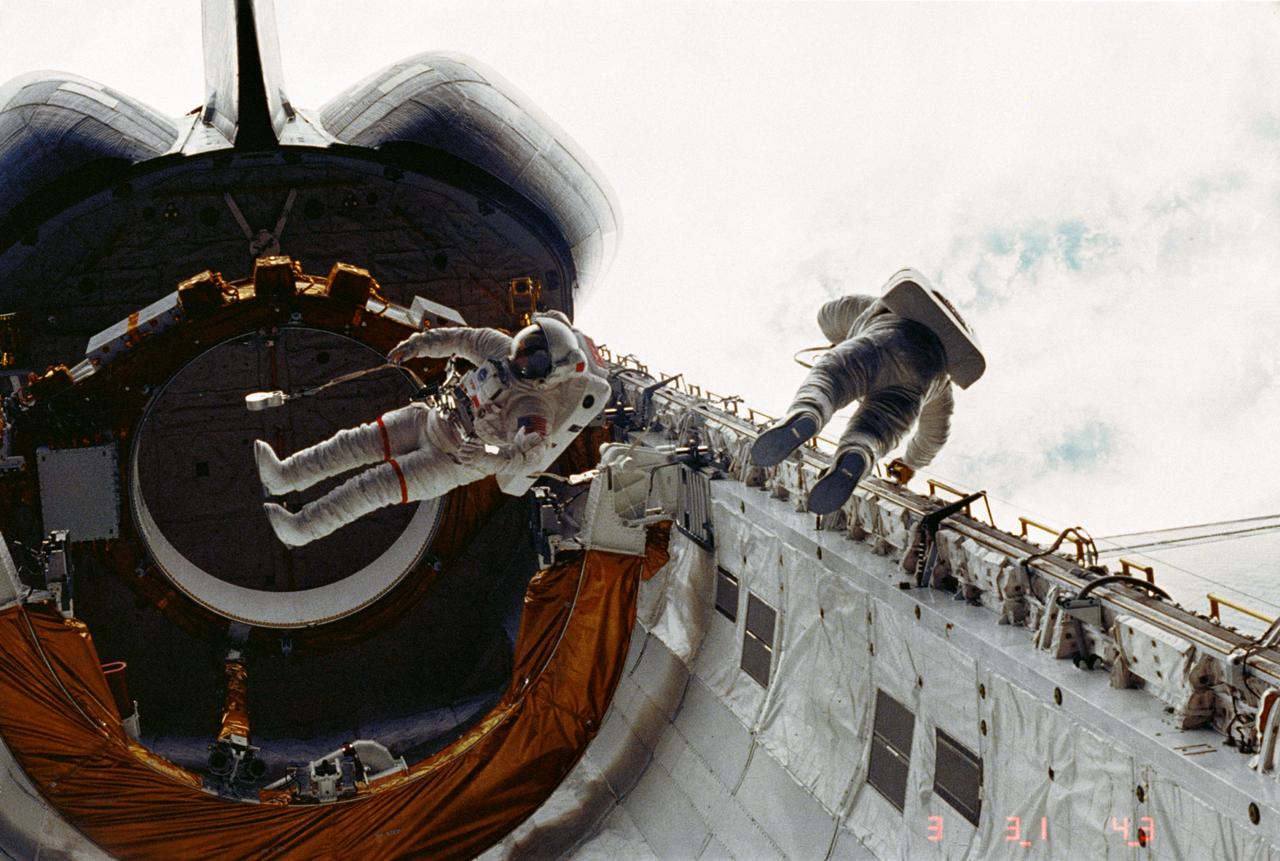
STS006-10-417 (7 April 1983) --- Astronauts F. Story Musgrave, left, and Donald H. Peterson float about in the cargo bay of the Earth-orbiting space shuttle Challenger during their April 7, 1983, extravehicular activity (EVA). Their "floating about" is restricted via tethers to safety slide wires. Thanks to the tether/slide wire combination, Peterson is able to translate along the port side hand rails. Musgrave is near the Airborne Support Equipment (ASE) for the now vacated Inertial Upper Stage (IUS). Clouds can be seen in the background. Photo credit: NASA
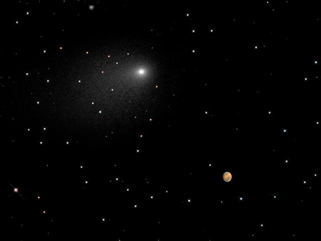
This composite NASA Hubble Space Telescope Image captures the positions of comet Siding Spring and Mars in a never-before-seen close passage of a comet by the Red Planet, which happened at 2:28 p.m. EDT October 19, 2014. The comet passed by Mars at approximately 87,000 miles (about one-third of the distance between Earth and the Moon). At that time, the comet and Mars were approximately 149 million miles from Earth. The comet image shown here is a composite of Hubble exposures taken between Oct. 18, 8:06 a.m. EDT to Oct. 19, 11:17 p.m. EDT. Hubble took a separate photograph of Mars at 10:37 p.m. EDT on Oct. 18. The Mars and comet images have been added together to create a single picture to illustrate the angular separation, or distance, between the comet and Mars at closest approach. The separation is approximately 1.5 arc minutes, or one-twentieth of the angular diameter of the full Moon. The background starfield in this composite image is synthesized from ground-based telescope data provided by the Palomar Digital Sky Survey, which has been reprocessed to approximate Hubble’s resolution. The solid icy comet nucleus is too small to be resolved in the Hubble picture. The comet’s bright coma, a diffuse cloud of dust enshrouding the nucleus, and a dusty tail, are clearly visible. This is a composite image because a single exposure of the stellar background, comet Siding Spring, and Mars would be problematic. Mars is actually 10,000 times brighter than the comet, and so could not be properly exposed to show detail in the Red Planet. The comet and Mars were also moving with respect to each other and so could not be imaged simultaneously in one exposure without one of the objects being motion blurred. Hubble had to be programmed to track on the comet and Mars separately in two different observations. The images were taken with Hubble’s Wide Field Camera 3. Credit: NASA, ESA, PSI, JHU/APL, STScI/AURA Credit: NASA, ESA, PSI, JHU/APL, STScI/AURA
The terrain in this observation from NASA Mars Reconnaissance Orbiter looks like an ancient uplifted crustal block. The area is riddled with faults big cracks that allow rocks to slide and ridges that look like uncovered magma dikes. A Mars Orbital Camera picture shows the region to be moderately dusty, but rocks do poke out along the ridges. With a high resolution images, we want to know if the dikes are of the same composition as the flood lavas that surround this high terrain. And what material did the dikes intrude upon which can be eroded away? http://photojournal.jpl.nasa.gov/catalog/PIA19287
ISS033-E-006447 (21 Sept. 2012) --- In the International Space Station’s Kibo laboratory, Japan Aerospace Exploration Agency astronaut Aki Hoshide, Expedition 33 flight engineer, works with the Small Satellite Orbital Deployer (SSOD) installed on the Multi-Purpose Experiment Platform (MPEP) of the extended slide table of the Kibo airlock.
iss042e015943 (11/26/2014) --- Commander Barry Wilmore unpacks the Cyclops launch platform for installation on the Japanese Experiment Module Airlock (JEMAL) slide table. The Cyclops platform, also known as the Space Station Integrated Kinetic Launcher for Orbital Payload Systems (SSIKLOPS), holds and ejects nanosatellites from outside the ISS.
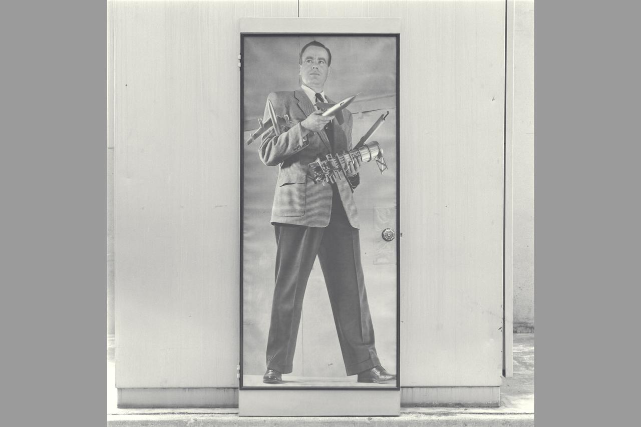
Historical Recruiting poster of Cleve E Voss holding model of B-47, Douglas D-558-2, 6x6ft w.t. & slide rule (on Display at Macy's San Francisco 1947 - 1950 ish) NOTE: Poster recovered from Voss's wife and copied from the (bedroom) door to which it had been adhered.
ISS033-E-006446 (21 Sept. 2012) --- In the International Space Station’s Kibo laboratory, Japan Aerospace Exploration Agency astronaut Aki Hoshide, Expedition 33 flight engineer, works with the Small Satellite Orbital Deployer (SSOD) installed on the Multi-Purpose Experiment Platform (MPEP) of the extended slide table of the Kibo airlock.
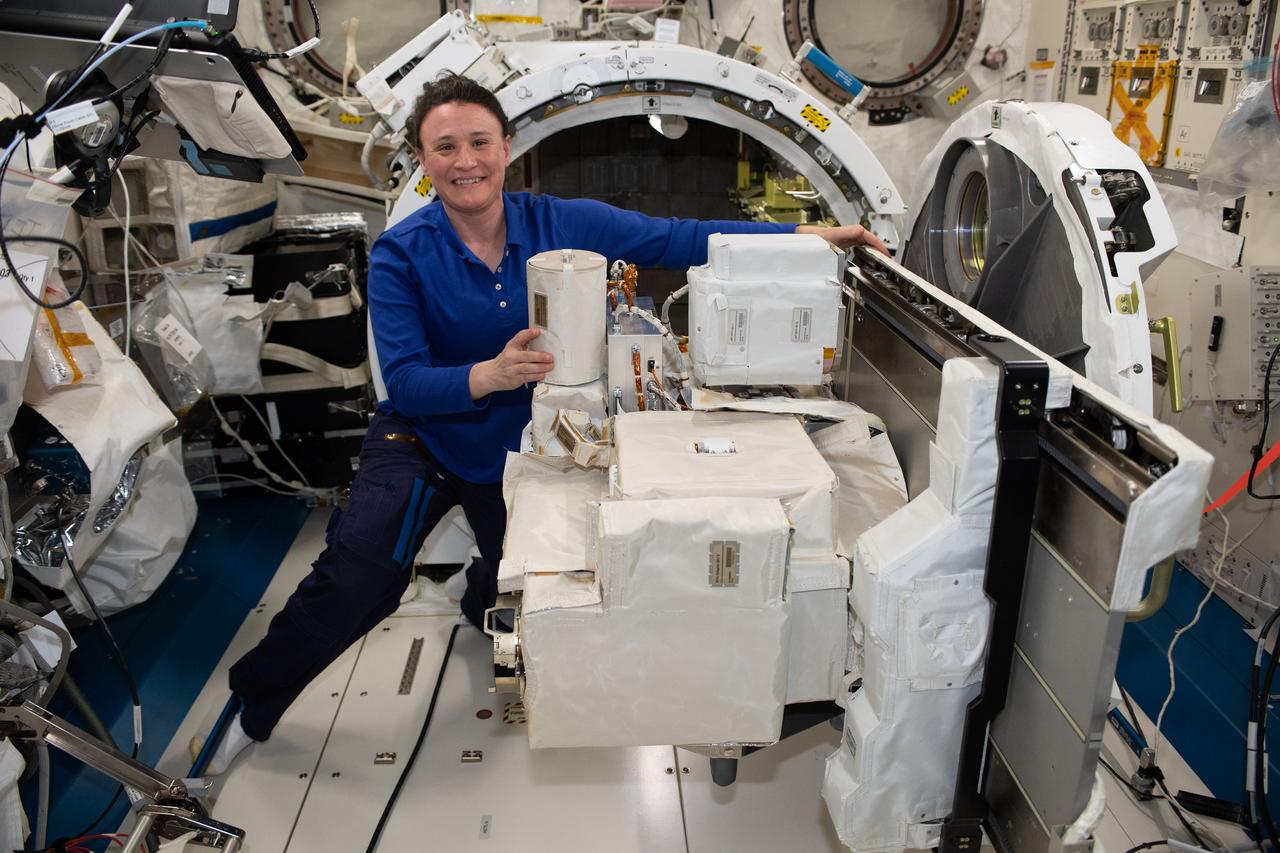
iss056e161171 (Sept. 6, 2018) --- NASA astronaut Serena Auñón-Chancellor works inside Japan's Kibo laboratory module replacing a high definition television camera unit on an exposed facility unit adapter. The gear was placed on Kibo's airlock slide table and later placed on the outside of the International Space Station.
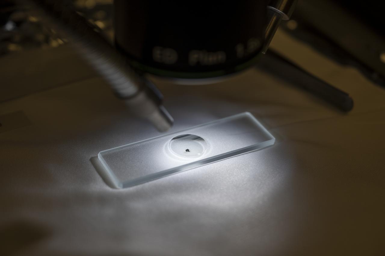
A sample from asteroid Bennu is seen prepared on a microscope slide, Friday, Nov. 3, 2023, at the Smithsonian’s National Museum of Natural History in Washington. The sample was collected from the carbon rich near Earth asteroid Bennu in October 2020 by NASA’s OSIRIS-REx spacecraft. Photo Credit: (NASA/Keegan Barber)
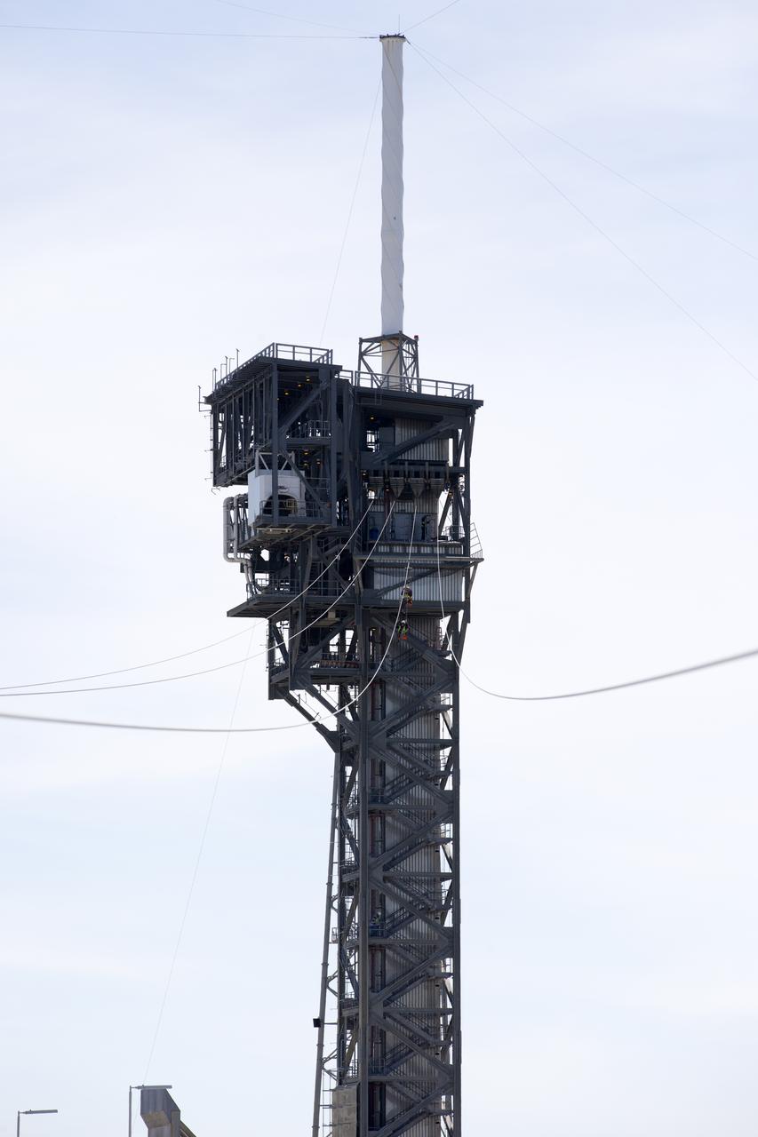
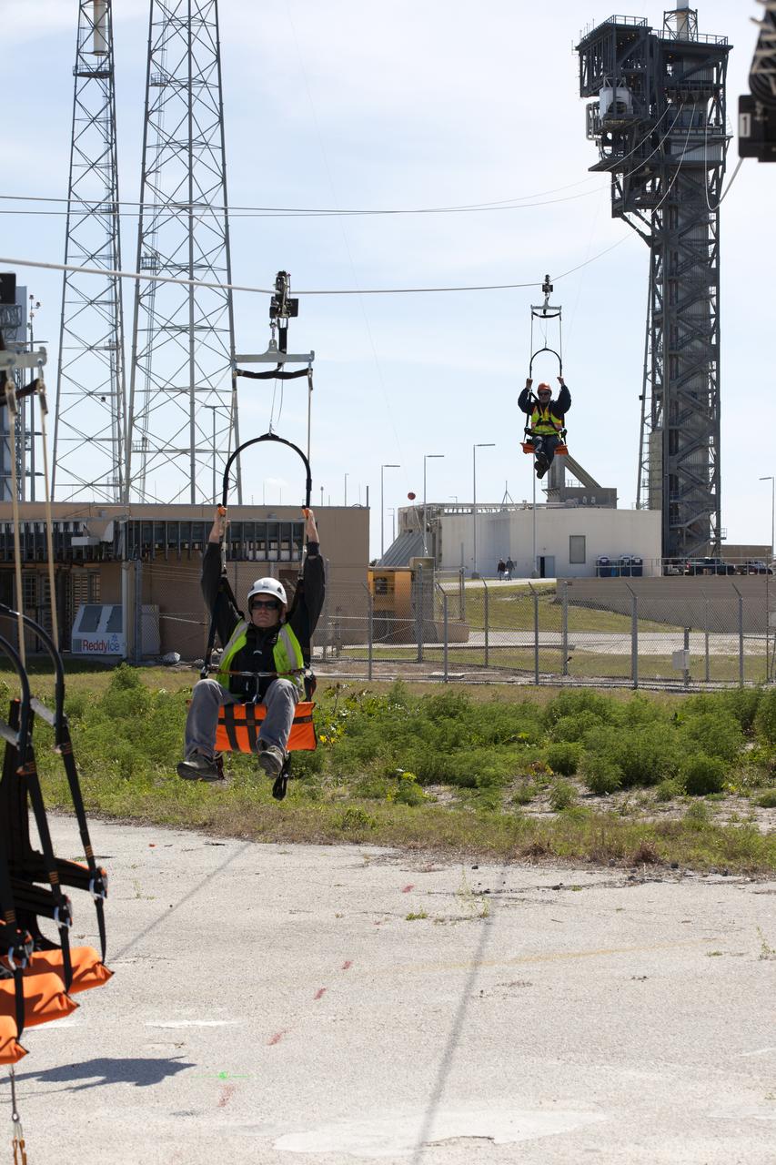
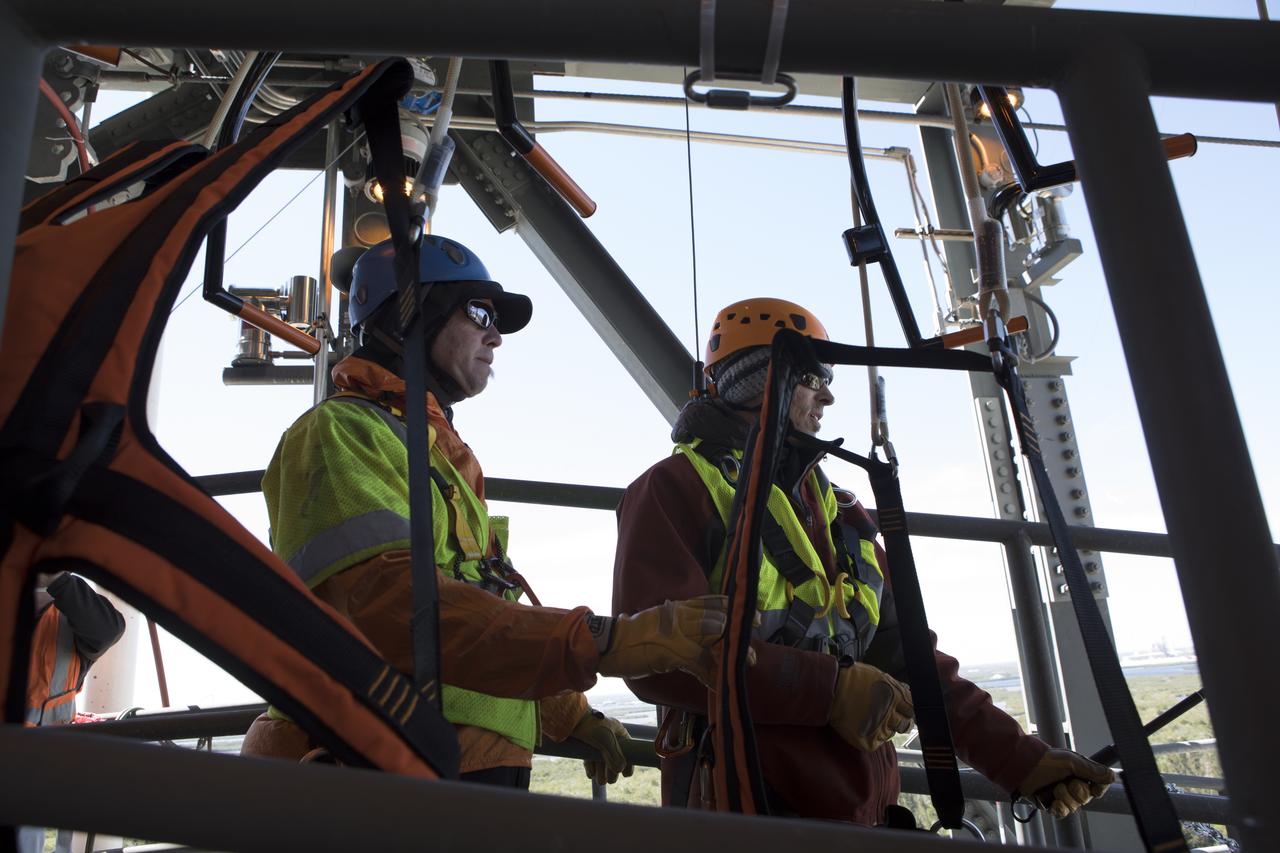
Two engineers evaluate the Emergency Egress System as they ride in folding seats attached to slide wires at Space Launch Complex 41. United Launch Alliance and Boeing continue modifications to the pad in order to host missions by the Boeing CST-100 Starliner carrying astronauts and crew. The system recently completed its final test. In the unlikely event of an emergency prior to liftoff, each person on the Crew Access Tower would get into their own seat attached to the wire and slide more than 1,340 feet to a safe area. The wires are situated 172 feet above the pad deck on level 12 of the tower. The Starliner will launch on a ULA Atlas V on mission to low-Earth orbit including those flying astronauts to the International Space Station during missions by NASA's Commercial Crew Program.
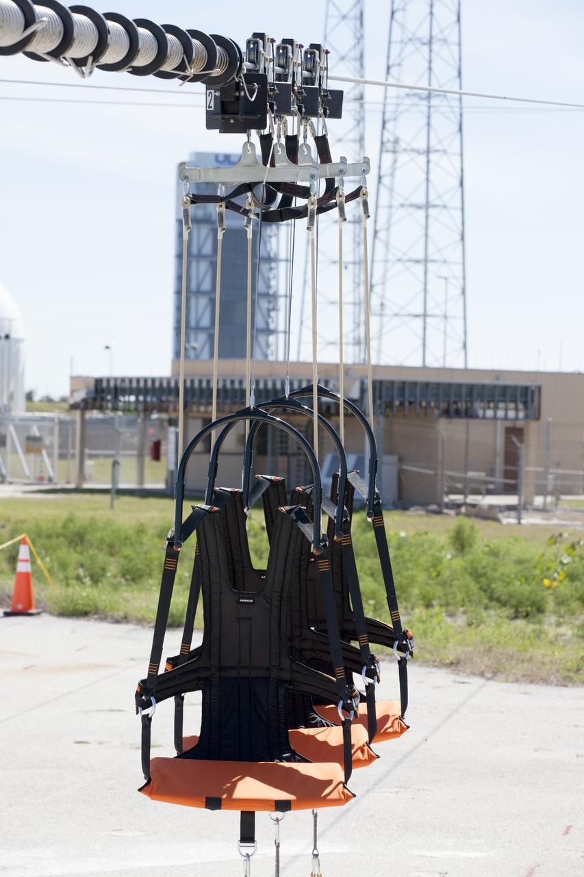
The folding seats that make up the Emergency Egress System are seen attached to slide wires at Space Launch Complex 41 where United Launch Alliance and Boeing continue modifications to the pad in order to host missions by the Boeing CST-100 Starliner carrying astronauts and crew. The system recently completed its final test. In the unlikely event of an emergency prior to liftoff, each person on the Crew Access Tower would get into their own seat attached to the wire and slide more than 1,340 feet to a safe area. The wires are situated 172 feet above the pad deck on level 12 of the tower. The Starliner will launch on a ULA Atlas V on mission to low-Earth orbit including those flying astronauts to the International Space Station during missions by NASA's Commercial Crew Program.
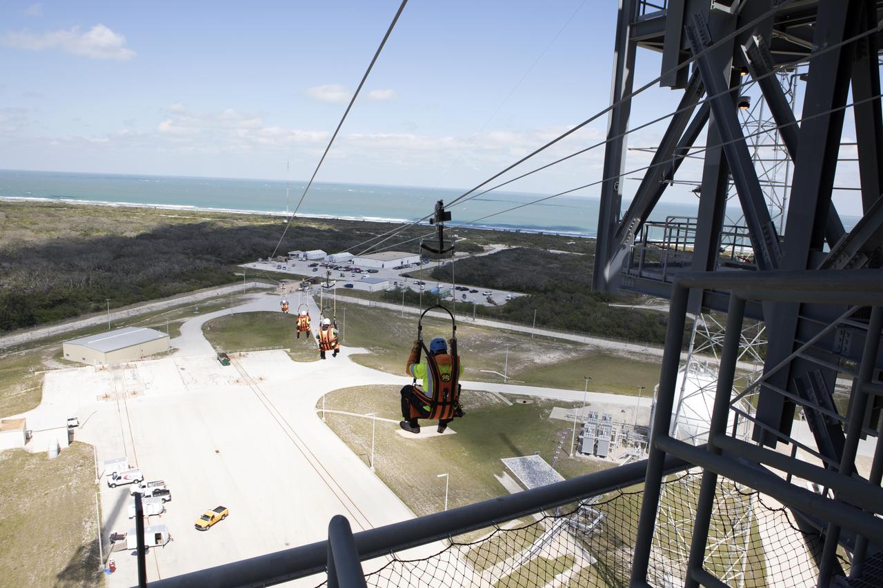
Engineers evaluate the Emergency Egress System as they ride in folding seats attached to slide wires at Space Launch Complex 41. United Launch Alliance and Boeing continue modifications to the pad in order to host missions by the Boeing CST-100 Starliner carrying astronauts and crew. The system recently completed its final test. In the unlikely event of an emergency prior to liftoff, each person on the Crew Access Tower would get into their own seat attached to the wire and slide more than 1,340 feet to a safe area. The wires are situated 172 feet above the pad deck on level 12 of the tower. The Starliner will launch on a ULA Atlas V on mission to low-Earth orbit including those flying astronauts to the International Space Station during missions by NASA's Commercial Crew Program.
Two engineers evaluate the Emergency Egress System as they ride in folding seats attached to slide wires at Space Launch Complex 41. United Launch Alliance and Boeing continue modifications to the pad in order to host missions by the Boeing CST-100 Starliner carrying astronauts and crew. The system recently completed its final test. In the unlikely event of an emergency prior to liftoff, each person on the Crew Access Tower would get into their own seat attached to the wire and slide more than 1,340 feet to a safe area. The wires are situated 172 feet above the pad deck on level 12 of the tower. The Starliner will launch on a ULA Atlas V on mission to low-Earth orbit including those flying astronauts to the International Space Station during missions by NASA's Commercial Crew Program.

Engineers evaluate the Emergency Egress System as they ride in folding seats attached to slide wires at Space Launch Complex 41. United Launch Alliance and Boeing continue modifications to the pad in order to host missions by the Boeing CST-100 Starliner carrying astronauts and crew. The system recently completed its final test. In the unlikely event of an emergency prior to liftoff, each person on the Crew Access Tower would get into their own seat attached to the wire and slide more than 1,340 feet to a safe area. The wires are situated 172 feet above the pad deck on level 12 of the tower. The Starliner will launch on a ULA Atlas V on mission to low-Earth orbit including those flying astronauts to the International Space Station during missions by NASA's Commercial Crew Program.
Three engineers prepare to evaluate the Emergency Egress System as they ride in folding seats attached to slide wires at Space Launch Complex 41. United Launch Alliance and Boeing continue modifications to the pad in order to host missions by the Boeing CST-100 Starliner carrying astronauts and crew. The system recently completed its final test. In the unlikely event of an emergency prior to liftoff, each person on the Crew Access Tower would get into their own seat attached to the wire and slide more than 1,340 feet to a safe area. The wires are situated 172 feet above the pad deck on level 12 of the tower. The Starliner will launch on a ULA Atlas V on mission to low-Earth orbit including those flying astronauts to the International Space Station during missions by NASA's Commercial Crew Program.
Engineers prepare to evaluate the Emergency Egress System as they ride in folding seats attached to slide wires at Space Launch Complex 41. United Launch Alliance and Boeing continue modifications to the pad in order to host missions by the Boeing CST-100 Starliner carrying astronauts and crew. The system recently completed its final test. In the unlikely event of an emergency prior to liftoff, each person on the Crew Access Tower would get into their own seat attached to the wire and slide more than 1,340 feet to a safe area. The wires are situated 172 feet above the pad deck on level 12 of the tower. The Starliner will launch on a ULA Atlas V on mission to low-Earth orbit including those flying astronauts to the International Space Station during missions by NASA's Commercial Crew Program.
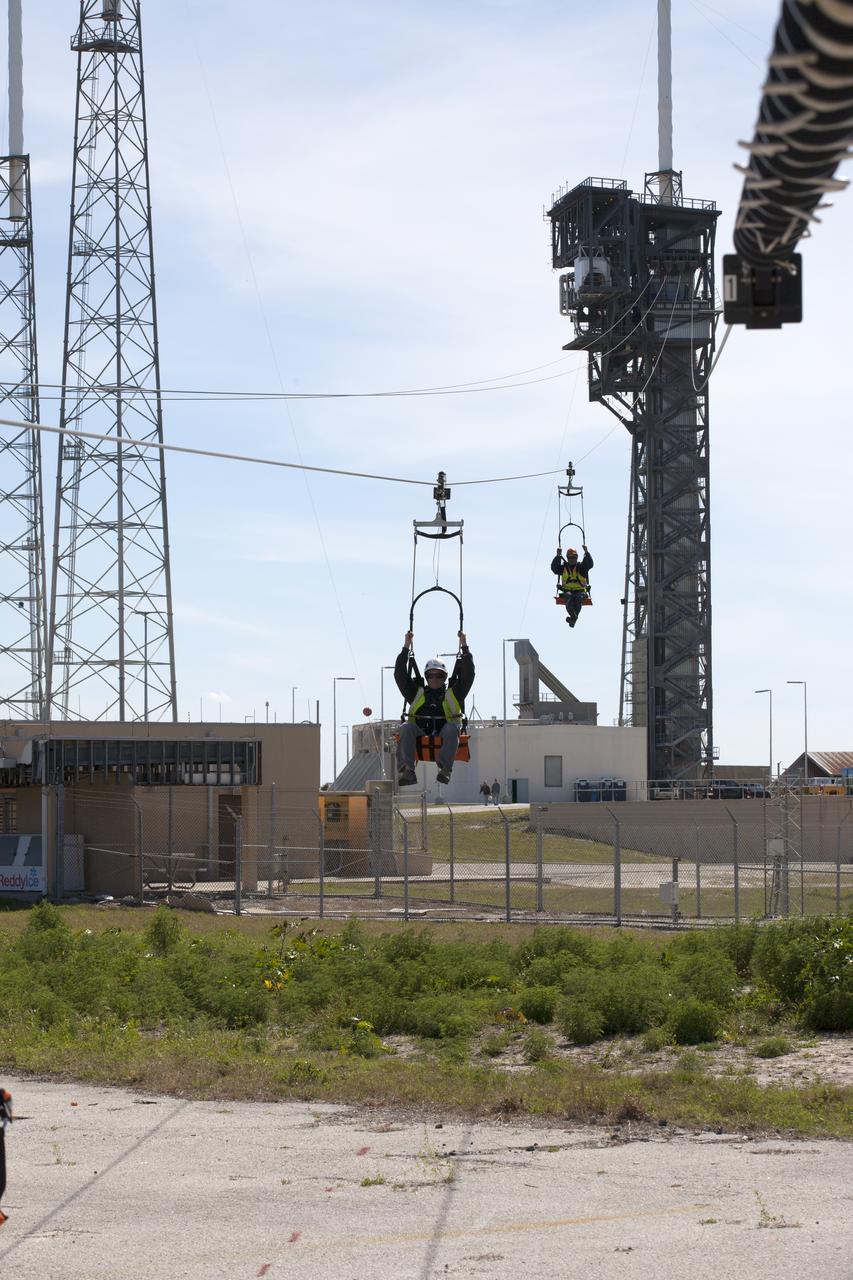
Two engineers evaluate the Emergency Egress System as they ride in folding seats attached to slide wires at Space Launch Complex 41. United Launch Alliance and Boeing continue modifications to the pad in order to host missions by the Boeing CST-100 Starliner carrying astronauts and crew. The system recently completed its final test. In the unlikely event of an emergency prior to liftoff, each person on the Crew Access Tower would get into their own seat attached to the wire and slide more than 1,340 feet to a safe area. The wires are situated 172 feet above the pad deck on level 12 of the tower. The Starliner will launch on a ULA Atlas V on mission to low-Earth orbit including those flying astronauts to the International Space Station during missions by NASA's Commercial Crew Program.
Two engineers prepare to evaluate the Emergency Egress System as they ride in folding seats attached to slide wires at Space Launch Complex 41. United Launch Alliance and Boeing continue modifications to the pad in order to host missions by the Boeing CST-100 Starliner carrying astronauts and crew. The system recently completed its final test. In the unlikely event of an emergency prior to liftoff, each person on the Crew Access Tower would get into their own seat attached to the wire and slide more than 1,340 feet to a safe area. The wires are situated 172 feet above the pad deck on level 12 of the tower. The Starliner will launch on a ULA Atlas V on mission to low-Earth orbit including those flying astronauts to the International Space Station during missions by NASA's Commercial Crew Program.
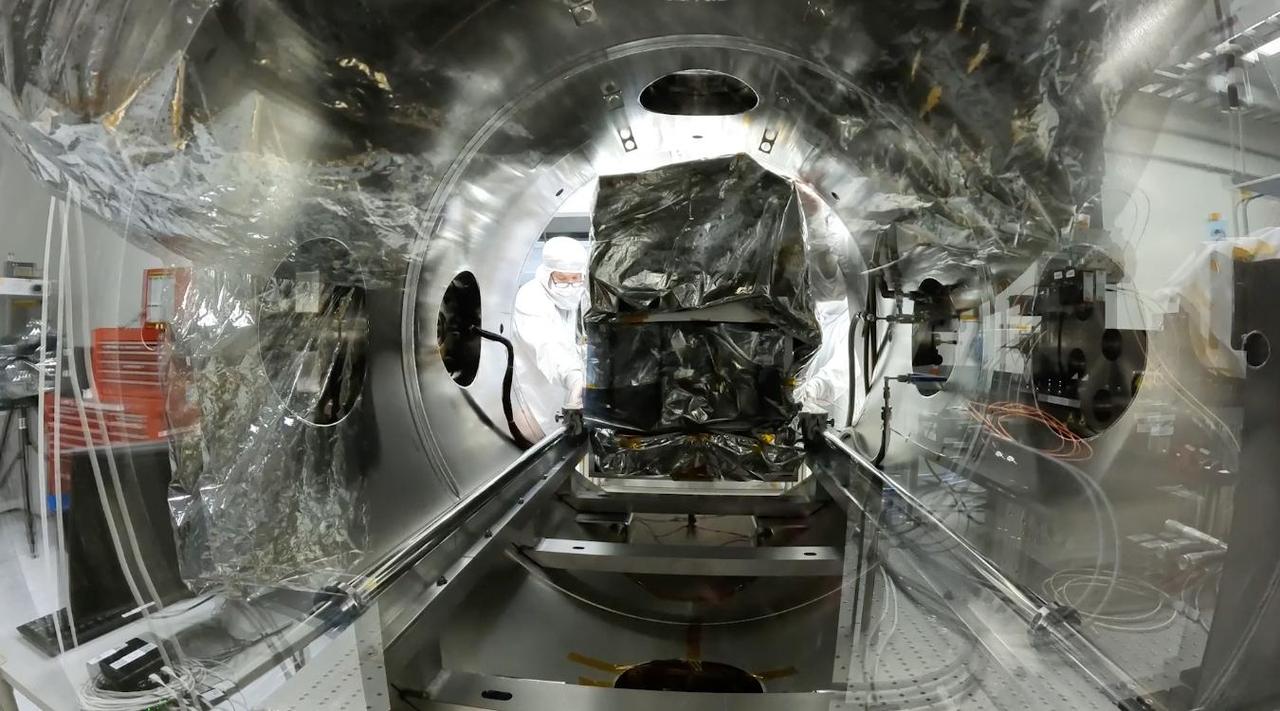
A technician slides an imaging spectrometer instrument, which will measure the greenhouse gases methane and carbon dioxide from space, into a thermal vacuum test chamber at NASA's Jet Propulsion Laboratory in Southern California in July 2023. The thermal vacuum chamber test is one of a series meant to ensure that the instrument can withstand the rigors of launch and the harsh conditions of space. Engineers use the chamber to subject the spectrometer to the extreme temperatures it will encounter in the vacuum of space. The instrument shipped Sept. 12, 2023, from JPL to Planet Labs PBC in San Francisco, where it will be integrated into a Tanager satellite. Designed and built by JPL, imaging spectrometer will be part of an effort led by the nonprofit Carbon Mapper organization to collect data on greenhouse gas point-source emissions. The information will help locate and quantify "super-emitters" – the small percentage of individual sources responsible for a significant fraction of methane and carbon dioxide emissions around the world. Movie available at https://photojournal.jpl.nasa.gov/catalog/PIA26098
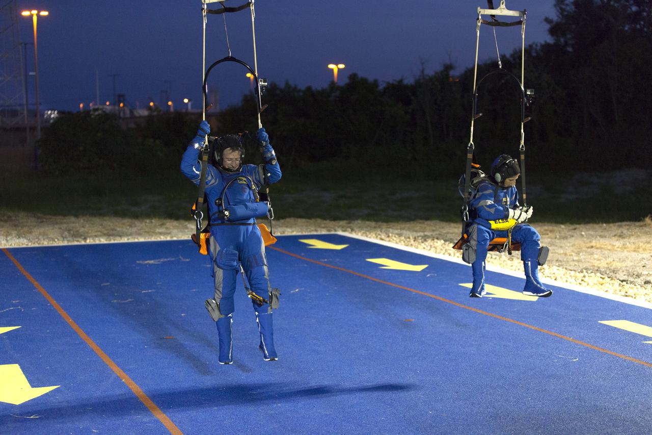
Astronauts participate in a Boeing/United Launch Alliance emergency egress system demonstration at Cape Canaveral Air Force Station’s Launch Complex 41 in Florida on June 19, 2018. The system features seats attached to slide wires which would carry astronauts and ground crew more than 1,300 feet away from the crew access tower in the unlikely event of an emergency prior to liftoff on launch day.
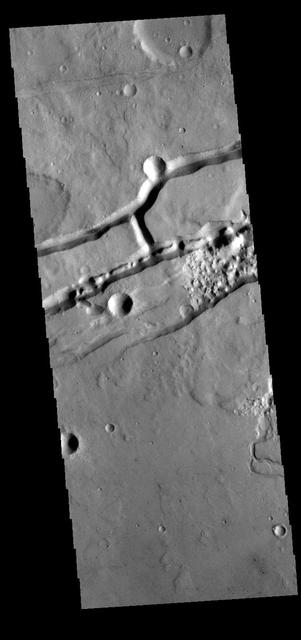
The linear depressions in this VIS image were created by tectonic forces. The sides of the depression are faults. Paired faults will allow the block of material between them to "slide down" during marsquake events, forming the depressions. Orbit Number: 77132 Latitude: 30.5611 Longitude: 285.586 Instrument: VIS Captured: 2019-05-05 08:37 https://photojournal.jpl.nasa.gov/catalog/PIA23260
The linear features in this VIS image is part of Labeatis Fossae. Fossae are linear depressions, most often caused by extensional tectonic forces pulling the crust apart and allowing material to slide downward between bounding faults. This type of feature is called a graben. Orbit Number: 85530 Latitude: 29.693 Longitude: 286.169 Instrument: VIS Captured: 2021-03-26 20:32 https://photojournal.jpl.nasa.gov/catalog/PIA24851
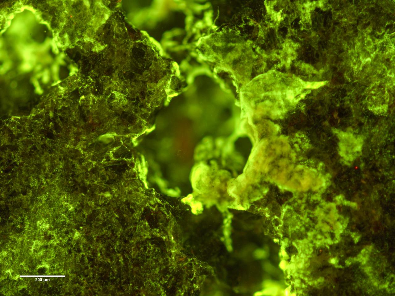
jsc2019e039825 (7/16/2019) --- Preflight Ffuorescence microscopy image of biofilm of Spingomonas desiccabilis growing over and into the surface of a basalt slide as part of BioRock experiment. Organisms are stained with DNA binding sye Sybr Gold. Growth can be seen into the rock cavities. The purpose of the Biorock investigation is to examine the effects of altered gravity on the rock/microbe/liquid system as a whole. (Image Courtesy of: ESA)

NASA astronaut Jeanette Epps, center, answers a question along slide NASA Administrator Jim Bridenstine, left, and NASA astronaut Doug Wheelock, right, during an interactive STEM discussion with students attending the 70th International Astronautical Congress, Wednesday, Oct. 23, 2019, at NASA Headquarters in Washington. Photo Credit: (NASA/Joel Kowsky)
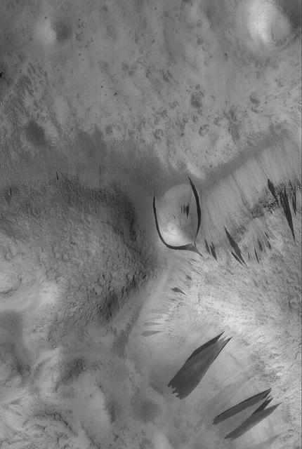
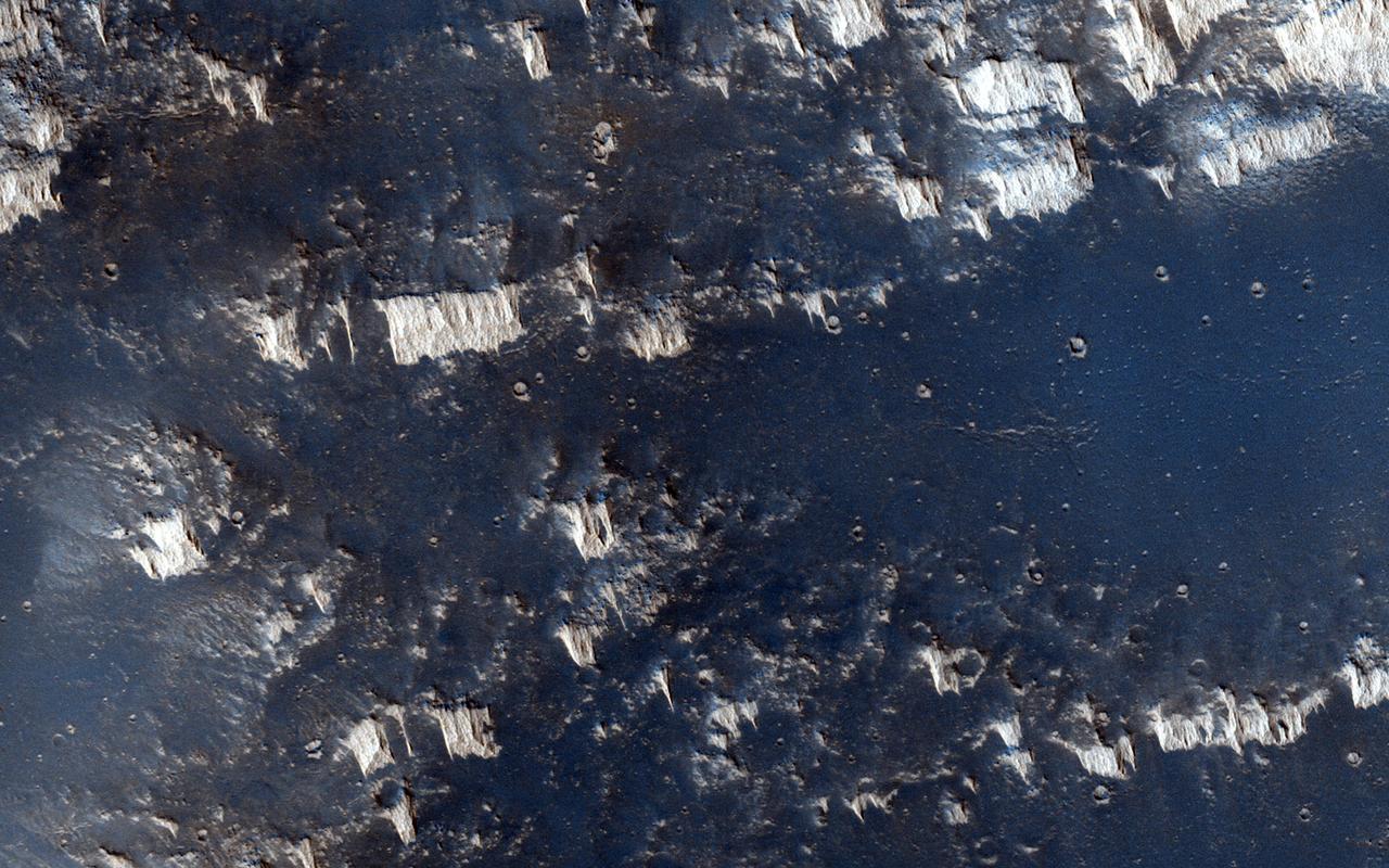
Dust and sand slide down slopes on Mars in little avalanches. Dark slope streaks are thought to be the result of the relatively bright colored dust avalanching down slopes, revealing the darker, coarser sand underneath. This image is the latest in a sequence of images of this crater that started in 2013. The goal is to watch the dusty slopes, and try to understand more about the processes that drive these little avalanches. https://photojournal.jpl.nasa.gov/catalog/PIA23757
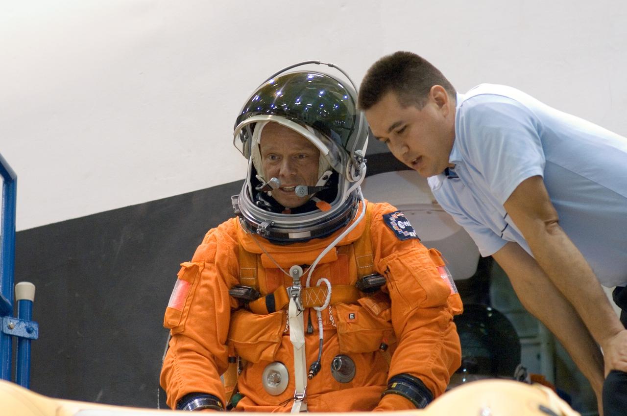
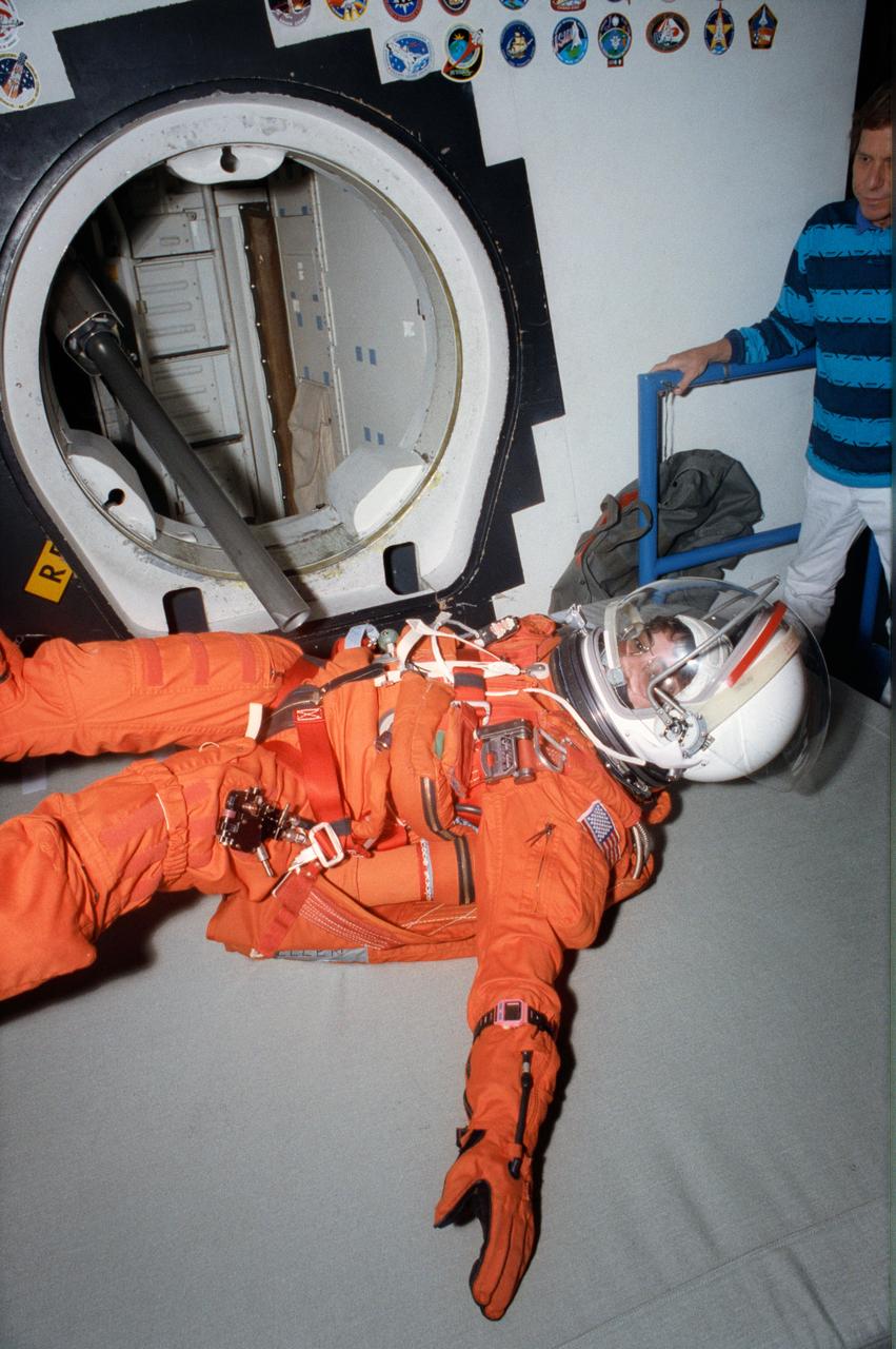
JSC2005-E-32723 (1 Aug. 2005) --- United Space Alliance (USA) crew trainer Adam Flagan briefs European Space Agency (ESA) astronaut Christer Fuglesang, STS-116 mission specialist, on the use of the crew escape slide in the crew compartment trainer (CCT) during emergency egress training. The CCT is one of several shuttle-training components located in the Space Vehicle Mockup Facility at the Johnson Space Center. Fuglesang is wearing a training version of the shuttle launch and entry suit.
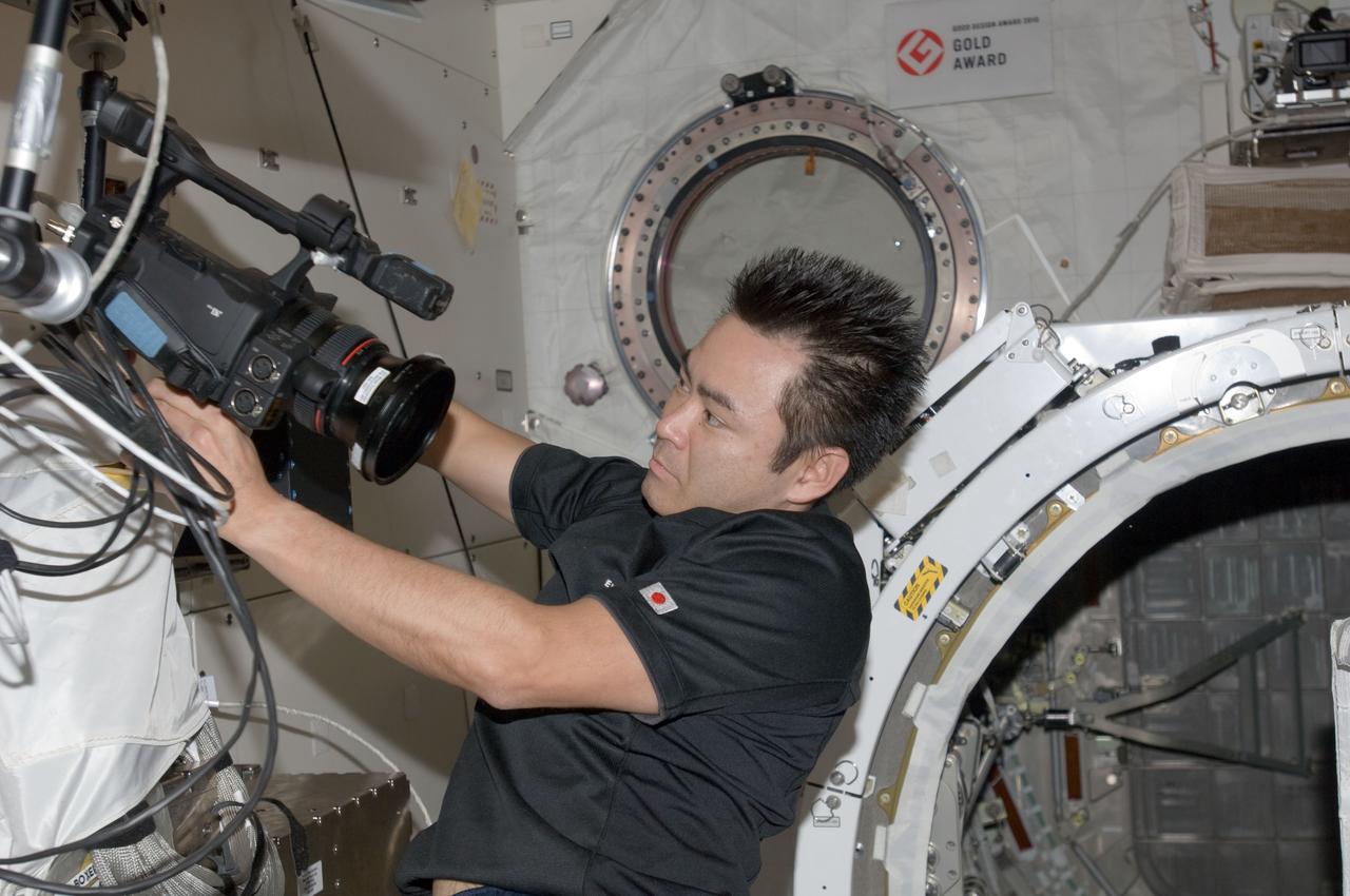
ISS033-E-006439 (21 Sept. 2012) --- In the International Space Station’s Kibo laboratory, Japan Aerospace Exploration Agency astronaut Aki Hoshide, Expedition 33 flight engineer, sets up a video camcorder in support of a ground checkout of the Small Satellite Orbital Deployer (SSOD) installed on the Multi-Purpose Experiment Platform (MPEP) of the extended slide table of the Kibo airlock.
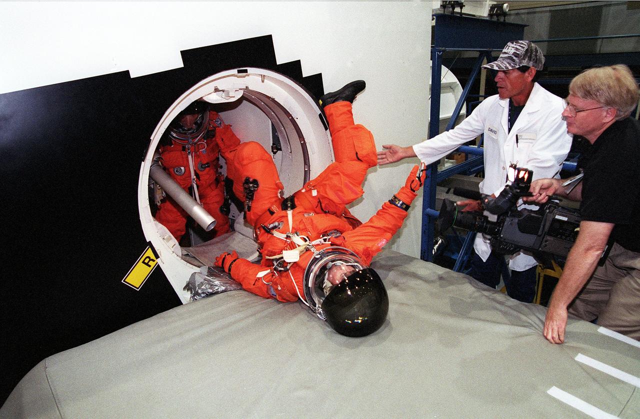
S99-05615 (19 May 1999) --- Astronaut Gerhard P.J. Thiele, mission specialist representing the European Space Agency (ESA), slides off the shuttle escape pole onto a soft surface during emergency bailout training for the STS-99 crew members. A second STS-99 crew member awaits his turn. Looking on are technician David Borjas (second right) and videographer Charles Clendaniel (right). The training took place at the crew compartment trainer (CCT) in the Systems Integration Facility at the Johnson Space Center (JSC).
A Commercial Crew astronaut participates in a Boeing/United Launch Alliance emergency egress system demonstration at Cape Canaveral Air Force Station’s Launch Complex 41 in Florida on June 19, 2018. The system features seats attached to slide wires which would carry astronauts and ground crew more than 1,300 feet away from the crew access tower in the unlikely event of an emergency prior to liftoff.
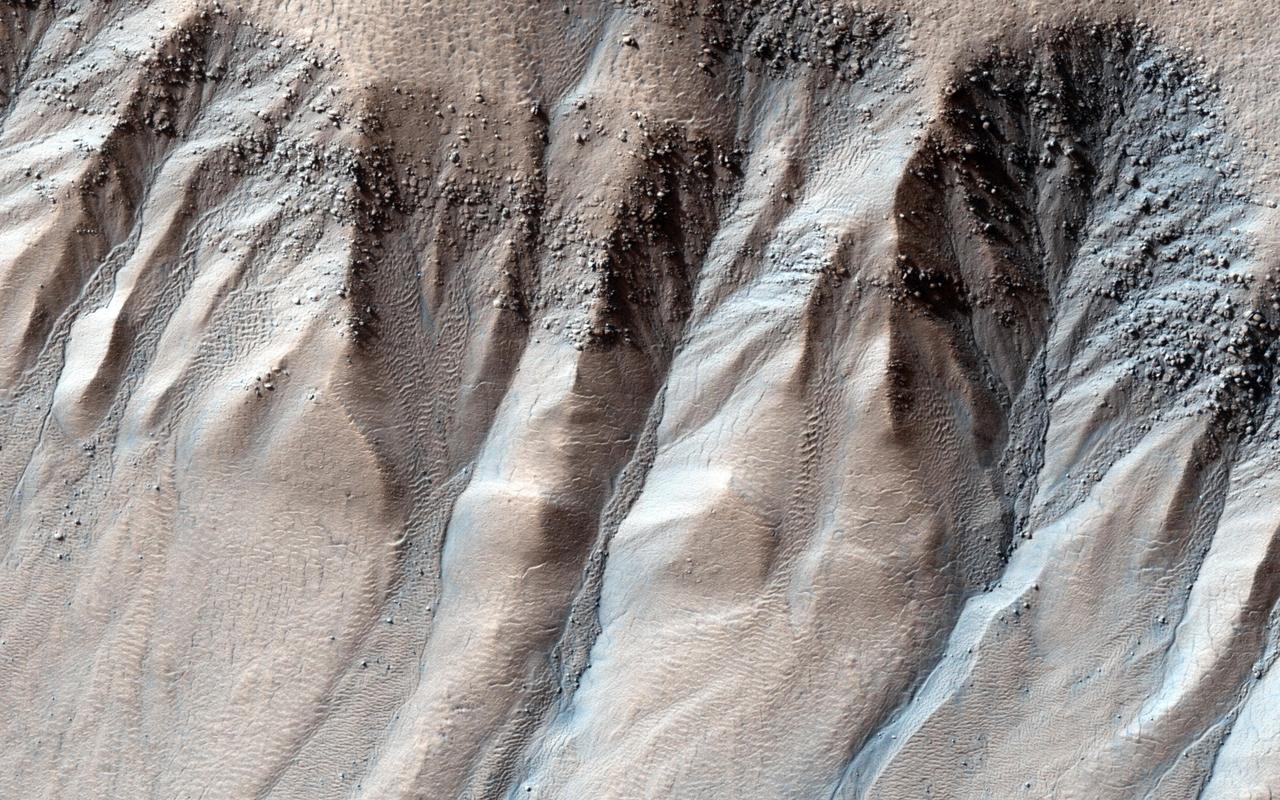
Gullies are often found on steep slopes. In the winter, this area is covered with a layer of carbon dioxide ice (dry ice). In the spring, when the ice warms up and transitions to gas, it dislodges material on the slope, forming a gully. In general, this process works best on fine material, leaving behind large boulders. These boulders can be seen collected in the gully alcoves. Occasionally, boulders slide or roll downhill, like those sprinkled downslope in this image. This set of gullies is found at -71 degrees latitude in the Southern hemisphere. http://photojournal.jpl.nasa.gov/catalog/PIA19295
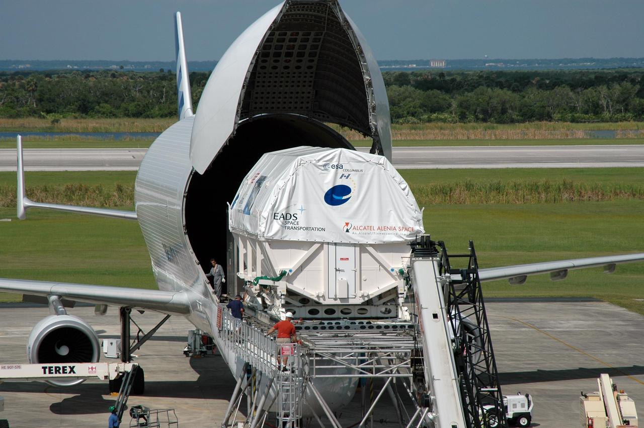
KENNEDY SPACE CENTER, FLA. - At the Shuttle Landing Facility, the European Space Agency's research laboratory, designated Columbus, slides out onto an Airbus Transport International platform. The module will be lifted onto a flat bed truck and transported to the Space Station Processing Facility. In the SSPF, the module will be prepared for delivery to the International Space Station on a future space shuttle mission. Columbus will expand the research facilities of the station and provide researchers with the ability to conduct numerous experiments in the area of life, physical and materials sciences. Photo credit: NASA/Jim Grossmann

Astronaut Suni Williams gets suited up in preparation for the Boeing/United Launch Alliance emergency egress system demonstration at Cape Canaveral Air Force Station’s Launch Complex 41 in Florida on June 19, 2018. The emergency egress system features seats that attach to slide wires. It can carry astronauts and ground crew more than 1,300 feet away from the crew access tower and the launch vehicle in the unlikely event of an emergency before liftoff.

iss064e035270 (Feb. 23, 2021) --- JAXA (Japan Aerospace Exploration Agency) astronaut and Expedition 64 Flight Engineer Soichi Noguchi is pictured after installing a three-dimensional virtual reality camera on the Kibo laboratory module's airlock slide table. The camera films activities aboard the orbiting lab in cinematic virtual reality to document living and working in space for audiences on Earth as part of the ISS Experience investigation.
This VIS image shows a section of Sirenum Fossae. The linear depression was created by tectonic forces stretching the surface. Paired faults allow blocks of the surface to slide down into the open space. The linear depression is called a graben. Orbit Number: 80616 Latitude: -27.3687 Longitude: 217.266 Instrument: VIS Captured: 2020-02-16 05:35 https://photojournal.jpl.nasa.gov/catalog/PIA23856
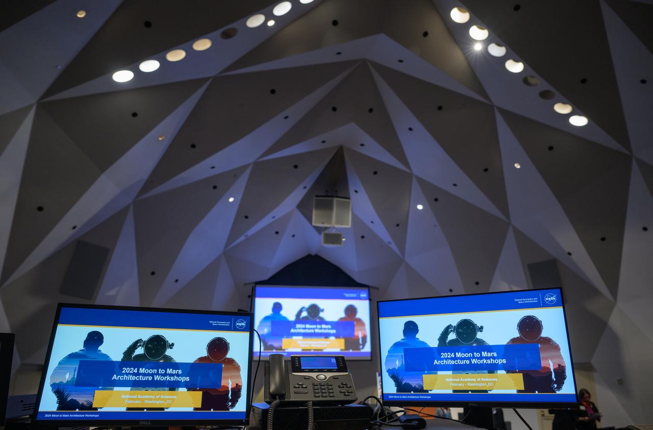
The opening presentation slide for the Moon to Mars Architecture Workshop is seen on monitors, Tuesday, Feb. 20, 2024, at the National Academy of Sciences in Washington. NASA held the workshop to engage the broader space community and collect feedback from U.S. industry and academia and international partners to inform NASA's Moon to Mars Architecture, the agency's roadmap for human exploration of the Moon and Mars. Photo Credit: (NASA/Bill Ingalls)
This VIS image shows part of Ceraunius Fossae. The linear depressions are fault bounded features called graben. Graben form from tectonic forces that are pulling apart the surface, created space for material to "slide down" along the fault. Alba Mons is surrounded by extensive regions of closely spaced graben. Ceraunius Fossae is located south of Alba Mons. Orbit Number: 78406 Latitude: 27.7831 Longitude: 248.084 Instrument: VIS Captured: 2019-08-18 06:29 https://photojournal.jpl.nasa.gov/catalog/PIA23484
This VIS image shows a section of Sirenum Fossae. The linear depressions were created by tectonic forces stretching the surface. Paired faults allow blocks of the surface to slide down into the open space. The linear depressions are called graben. A small channel is visible on the lower right side of the image. Orbit Number: 81889 Latitude: -29.5423 Longitude: 212.521 Instrument: VIS Captured: 2020-05-31 01:12 https://photojournal.jpl.nasa.gov/catalog/PIA24087
S93-31980 (April 1993) --- Attired in a training version of the Shuttle launch and entry garment, astronaut Nancy J. Sherlock participates in a bailout training session at the Johnson Space Center's (JSC) systems integration facility. Training as a mission specialist for the STS-57 mission, Sherlock was rehearsing using the slide pole escape device. EDITOR'S NOTE: Nancy J. Currie (formerly Sherlock) has been assigned as a mission specialist for the STS-70 mission, scheduled for launch in spring of 1995.
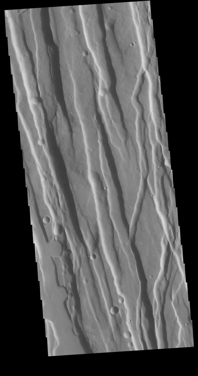
Today's VIS image shows a section of one of the graben that comprise Elysium Fossae. Graben are formed during tectonic activity, where blocks of material slide down between paired faults. Graben are common around volcanic regions on Mars. The rise of magma to the surface bows up the ground, creating the extensive forces that create graben. Orbit Number: 77698 Latitude: 22.948 Longitude: 156.114 Instrument: VIS Captured: 2019-06-20 23:13 https://photojournal.jpl.nasa.gov/catalog/PIA23366

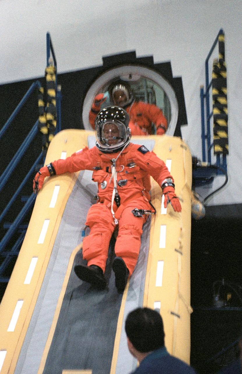
JSC2003-E-54284 (15 Aug. 2003) --- Astronaut Joan E. Higginbotham, STS-116 mission specialist, uses the crew escape slide in the crew compartment trainer (CCT) during emergency egress training. The CCT is one of several shuttle-training components located in the Space Vehicle Mockup Facility at the Johnson Space Center. Higginbotham is wearing a training version of the shuttle launch and entry suit. United Space Alliance (USA) crew trainer Adam G. Flagan assisted Higginbotham.
JSC2002-01537 (8 August 2002) --- Astronaut Christer Fuglesang, STS-116 mission specialist, uses the crew escape slide in the crew compartment trainer (CCT) during emergency egress training. The CCT is one of several shuttle-training components located in the Space Vehicle Mockup Facility at the Johnson Space Center (JSC). Fuglesang represents the European Space Agency (ESA).
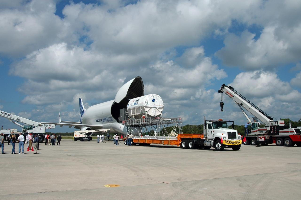
KENNEDY SPACE CENTER, FLA. - At the Shuttle Landing Facility, the European Space Agency's research laboratory, designated Columbus, slides out onto an Airbus Transport International platform. The module will be lifted onto a flat bed truck and transported to the Space Station Processing Facility. There the module will be prepared for delivery to the International Space Station on a future space shuttle mission. Columbus will expand the research facilities of the station and provide researchers with the ability to conduct numerous experiments in the area of life, physical and materials sciences. Photo credit: NASA/Jim Grossmann
This VIS image shows part of Cerunius Fossae. The linear depressions are fault bounded features called graben. These features form from tectonic forces that are pulling apart the surface, created space for material to "slide down" along the fault. Orbit Number: 77308 Latitude: 26.9347 Longitude: 248.025 Instrument: VIS Captured: 2019-05-19 20:27 https://photojournal.jpl.nasa.gov/catalog/PIA23283