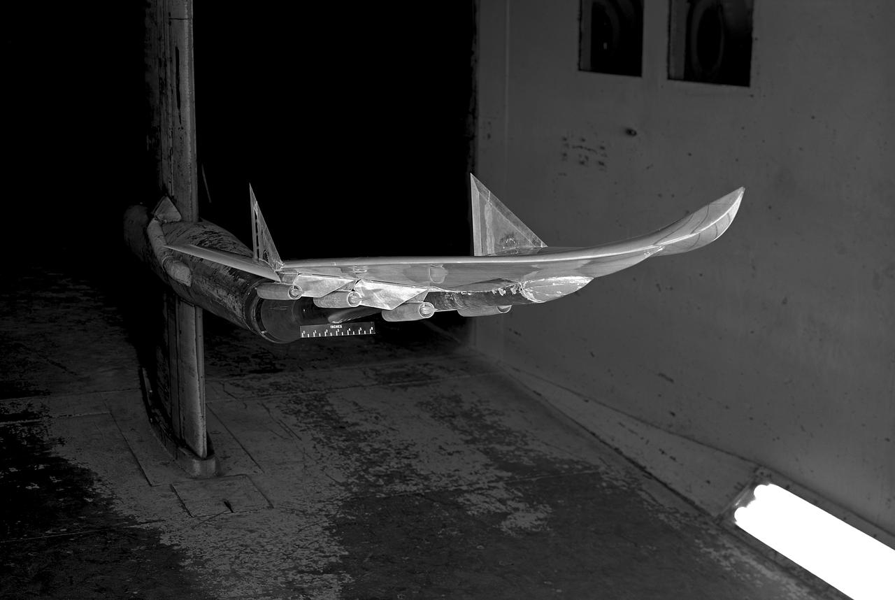
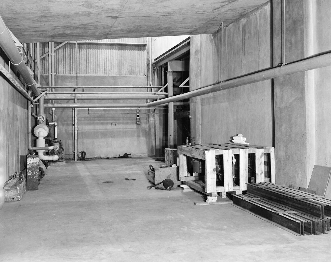
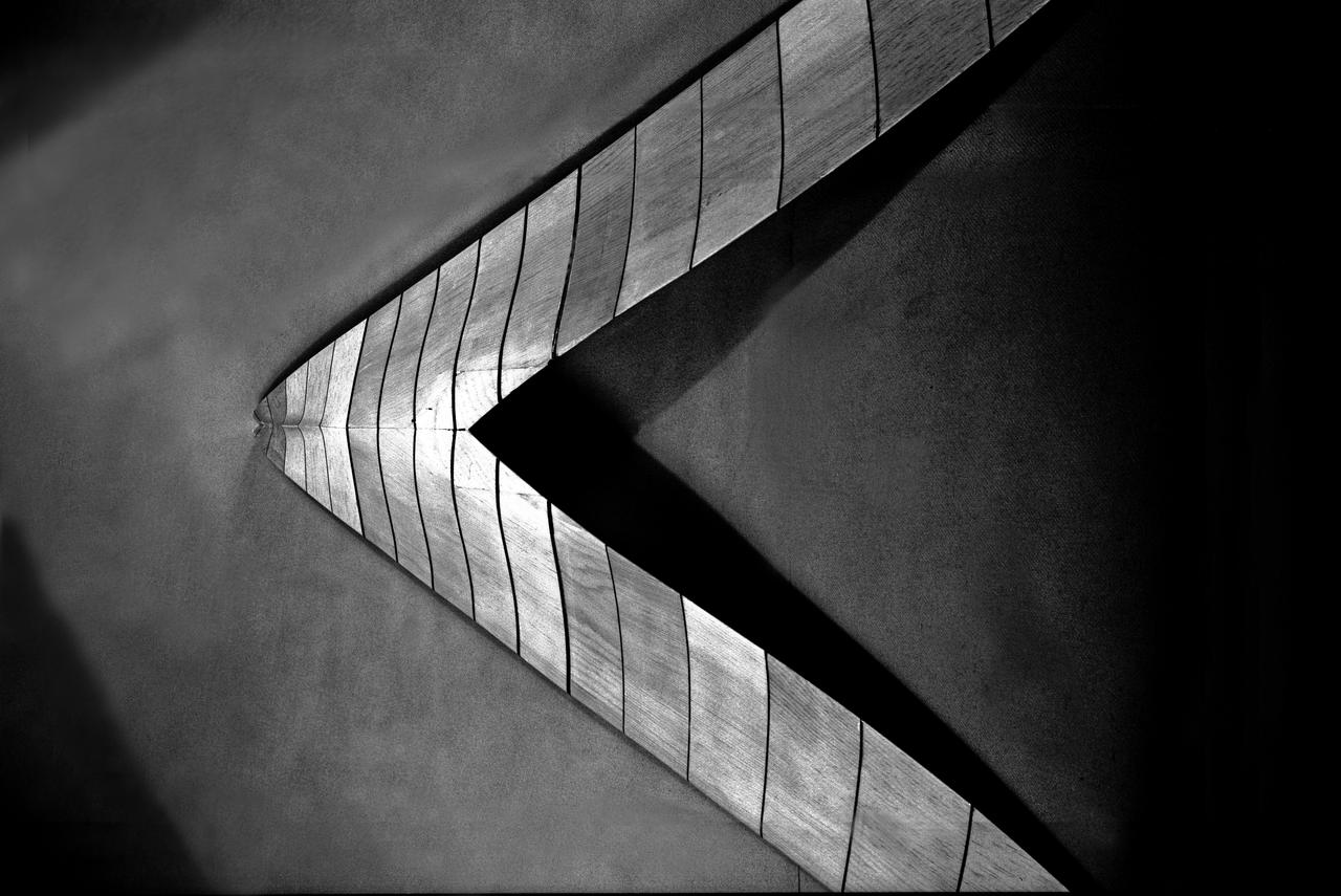
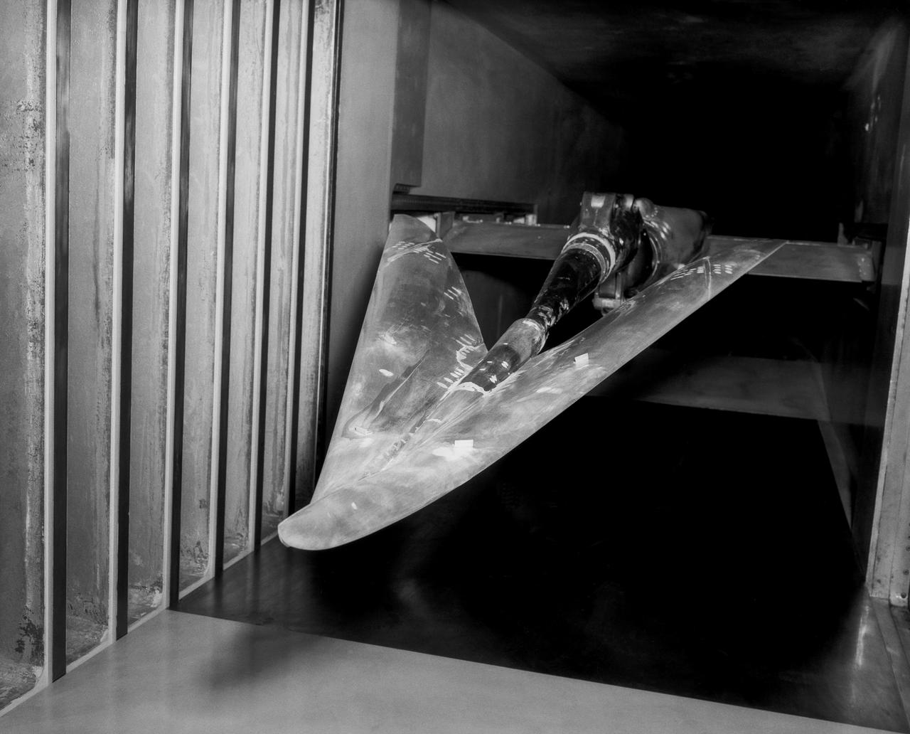
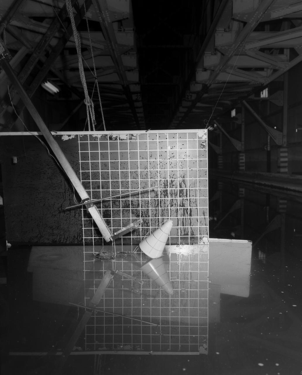
Research Model in the 7x10 High Speed Tunnel Building 1212B 300 mph tunnel
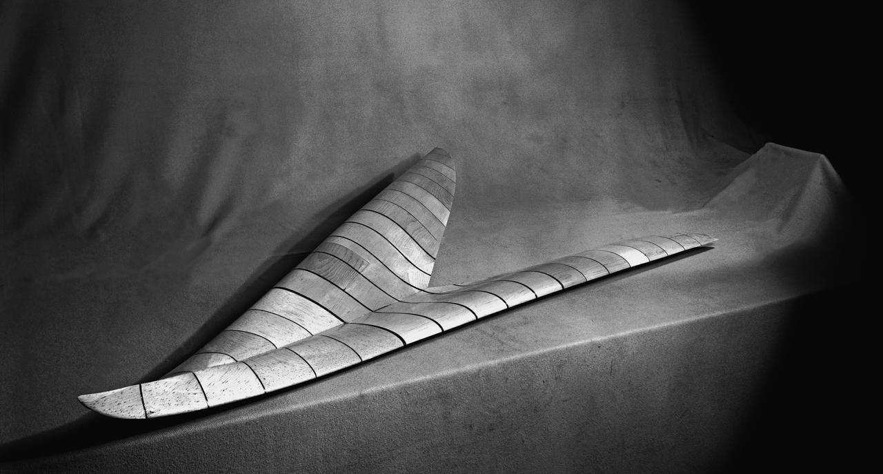
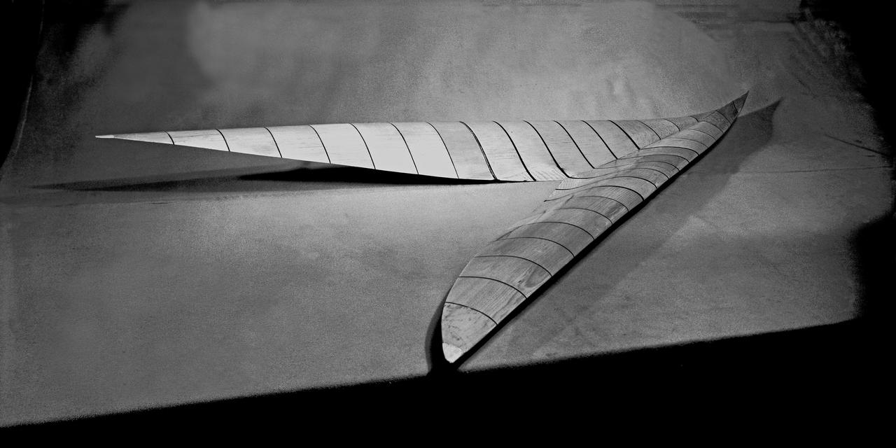
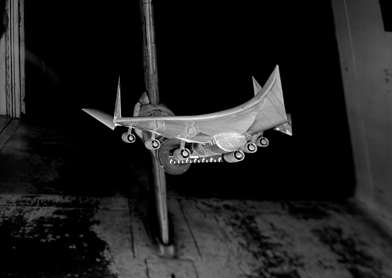
Wood Mock-up of Arrow Wing Bomber to Show Wing Contours
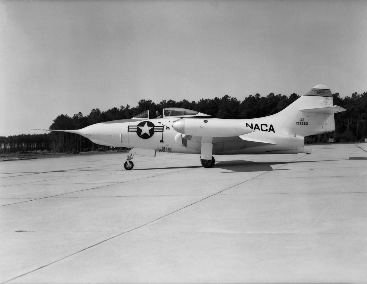
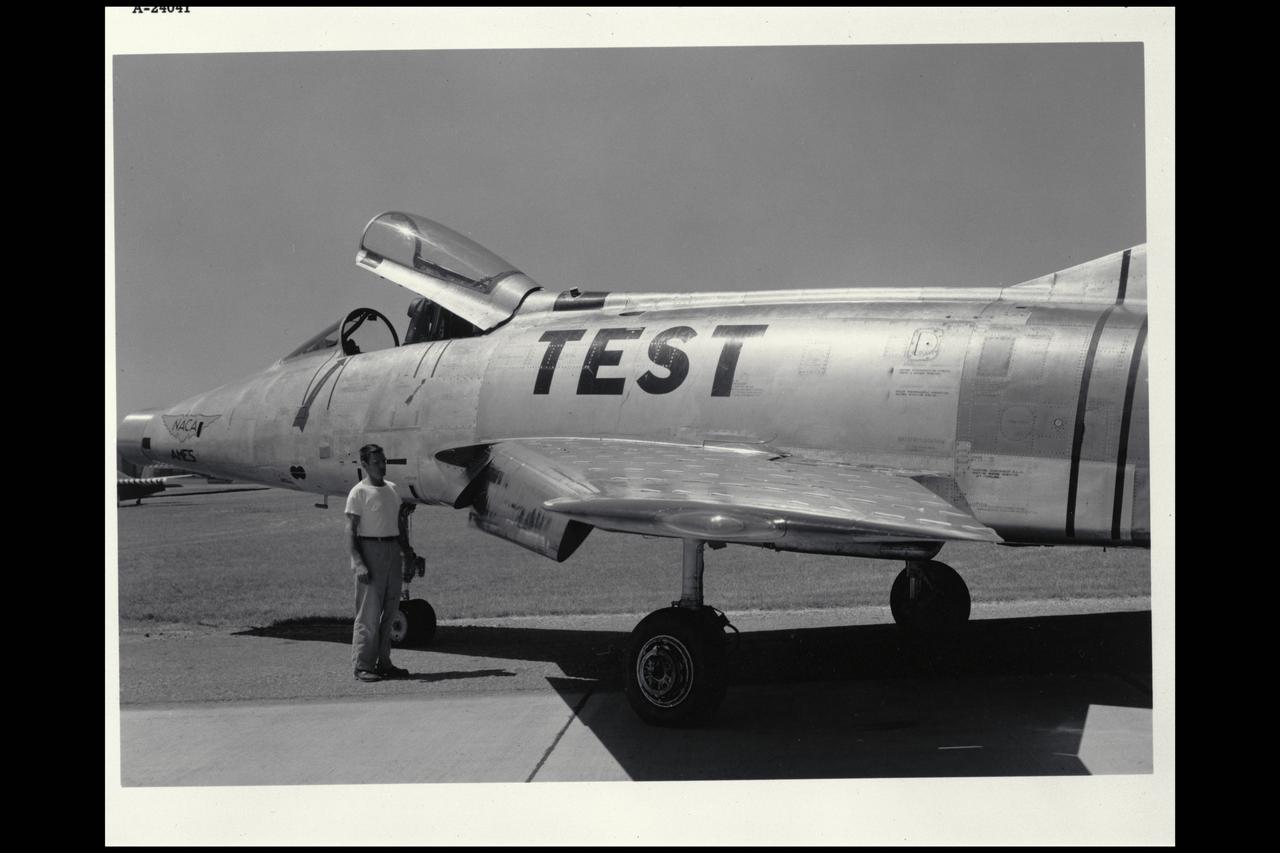
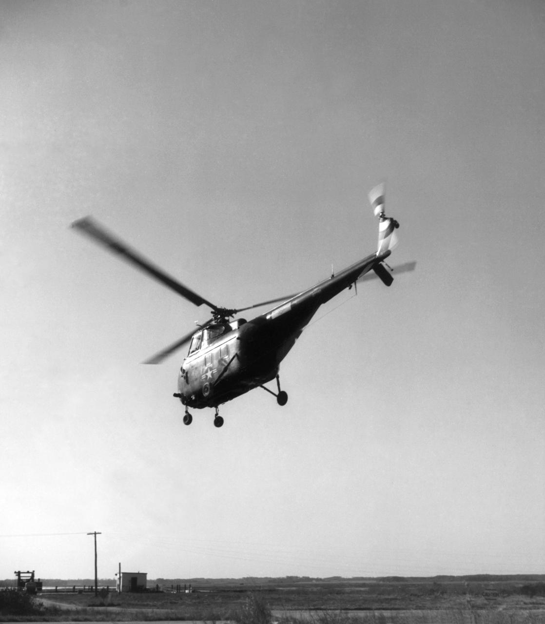
Grumman F9F-2 Panther: Originally built as a F9F-3, this Grumman F9F-2 Panther has a Pratt and Whitney J42 turbojet power plant, hence the designation change. This Panther underwent handling quality tests, serving long enough at Langley to witness the change from the NACA to NASA.
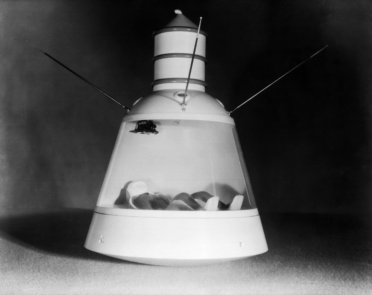
Scale model of Mercury capsule shape A, indicating the position of the astronaut.
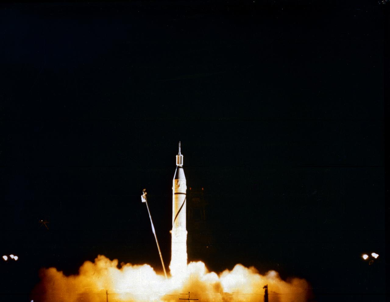
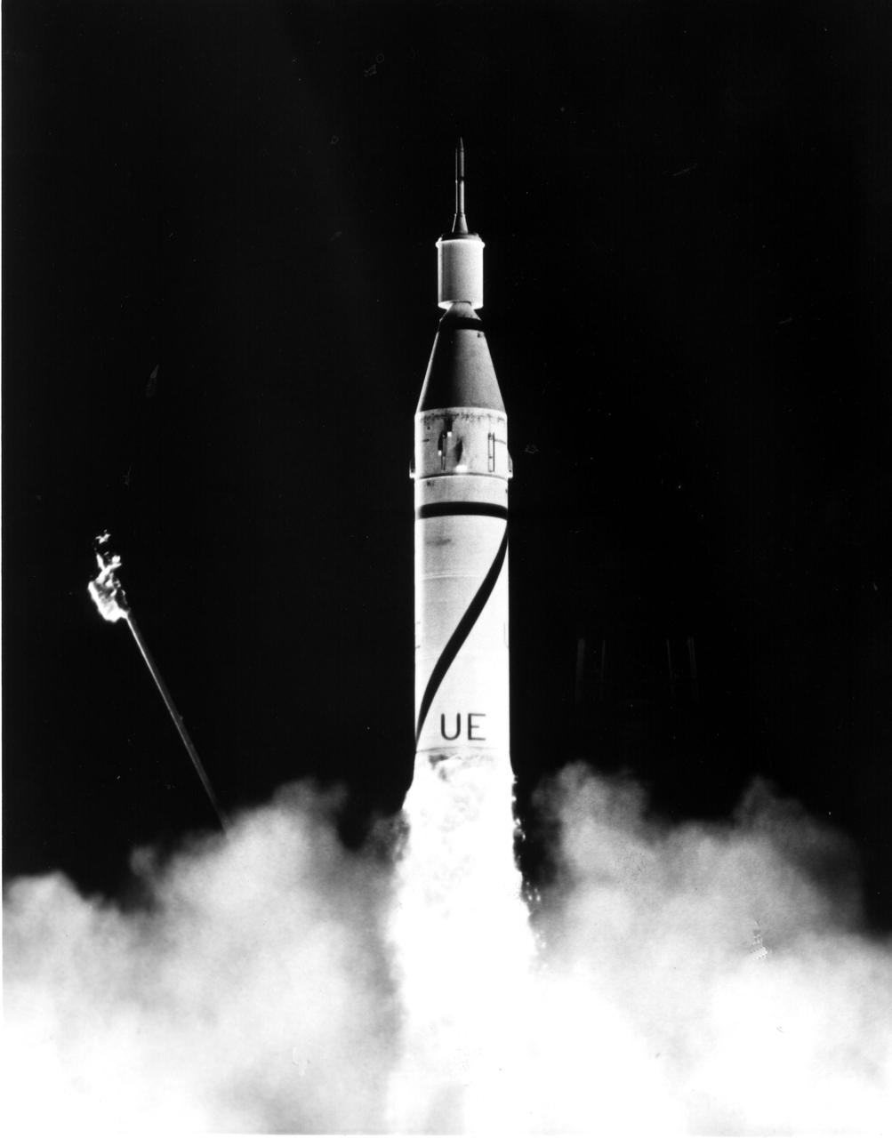
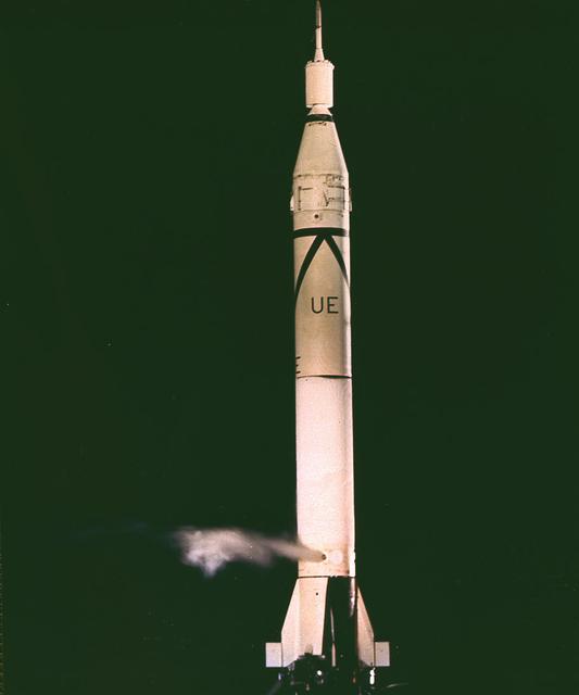
Launch of Jupiter-C/Explorer 1 at Cape Canaveral, Florida on January 31, 1958. After the Russian Sputnik 1 was launched in October 1957, the launching of an American satellite assumed much greater importance. After the Vanguard rocket exploded on the pad in December 1957, the ability to orbit a satellite became a matter of national prestige. On January 31, 1958, slightly more than four weeks after the launch of Sputnik.The ABMA (Army Ballistic Missile Agency) in Redstone Arsenal, Huntsville, Alabama, in cooperation with the Jet Propulsion Laboratory, launched a Jupiter from Cape Canaveral, Florida. The rocket consisted of a modified version of the Redstone rocket's first stage and two upper stages of clustered Baby Sergeant rockets developed by the Jet Propulsion Laboratory and later designated as Juno boosters for space launches
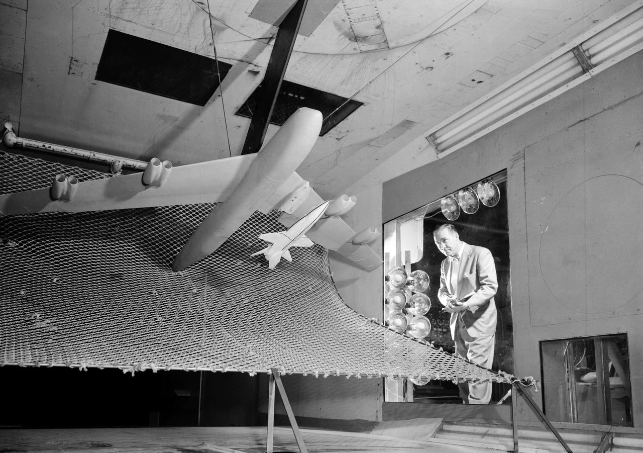
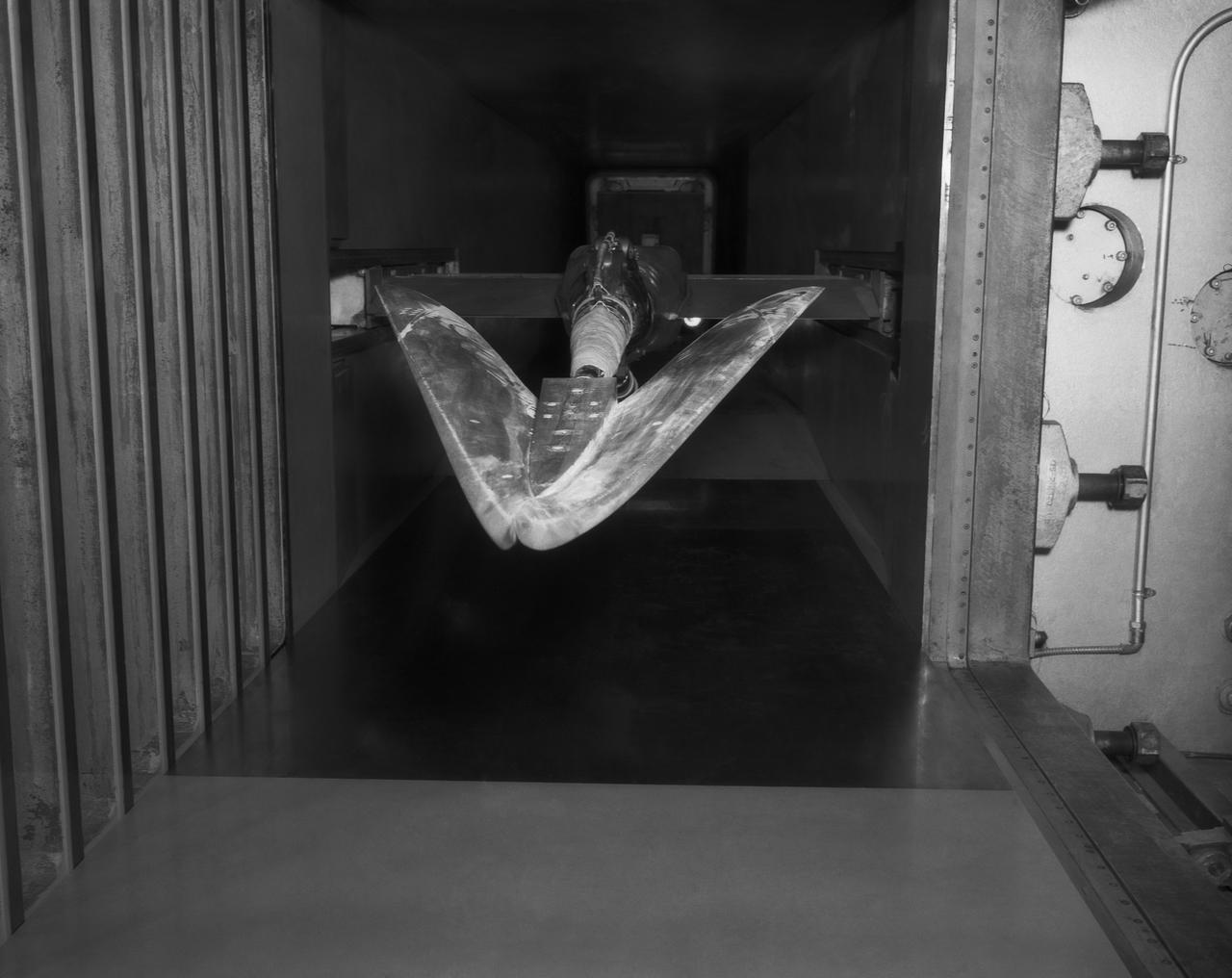
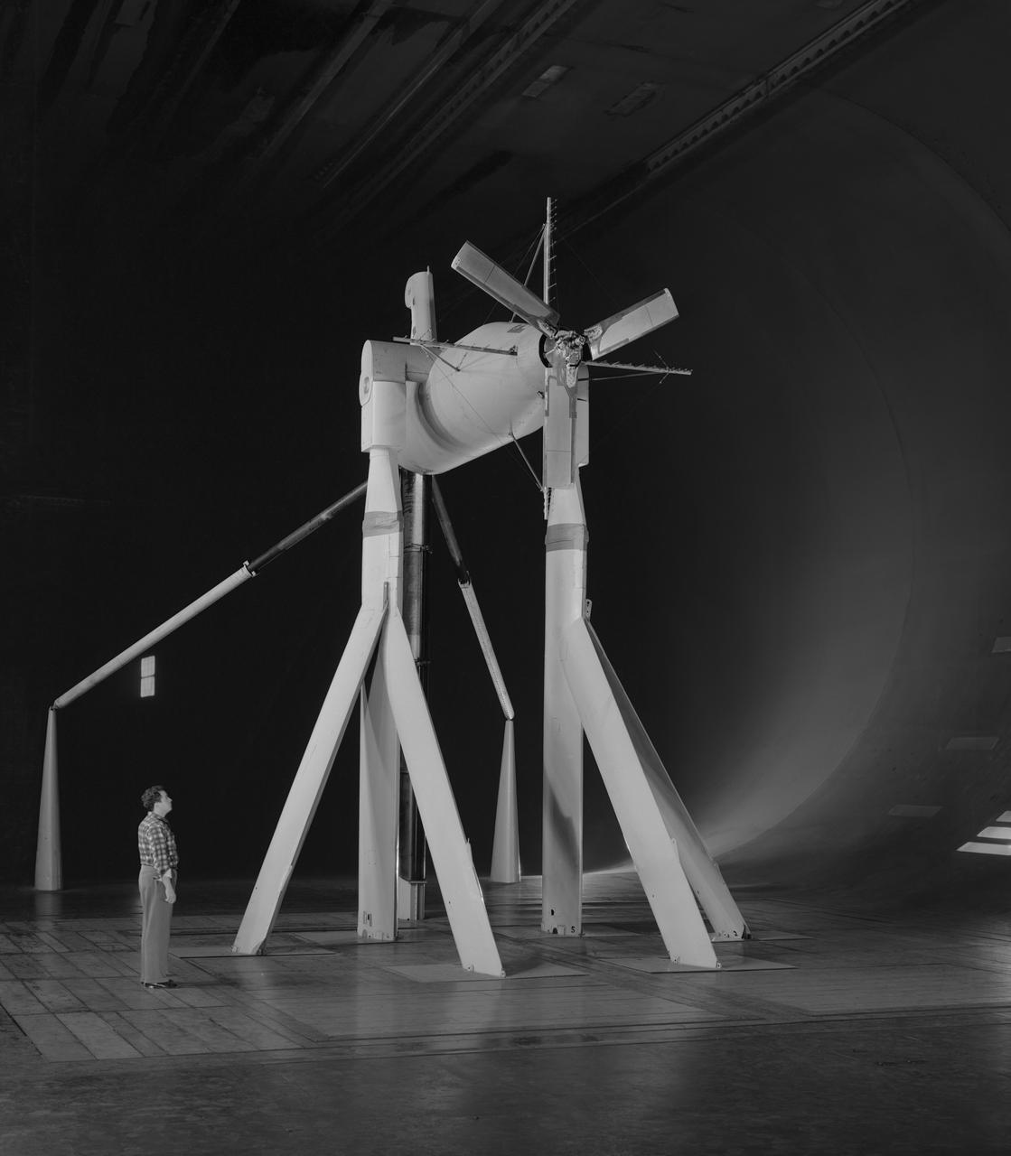
A one-twentieth scale model of the X-15 originally suspended beneath the wing of a B-52 is observed by a scientist of the National Aeronautics and Space Administration (NASA) as it leaves the bomber model in tests to determine the release characteristics and drop motion of the research airplane. Caption: The aerodynamics of air launching the North American X-15 being investigated in the 300MPH Low Speed 7x10 Tunnel, about 1957. Photograph published in Engineer in Charge: A History of the Langley Aeronautical Laboratory, 1917-1958 by James R. Hansen. Page 366. Photograph also published in Sixty Years of Aeronautical Research 1917-1977 By David A. Anderton. A NASA publication. Page 49.
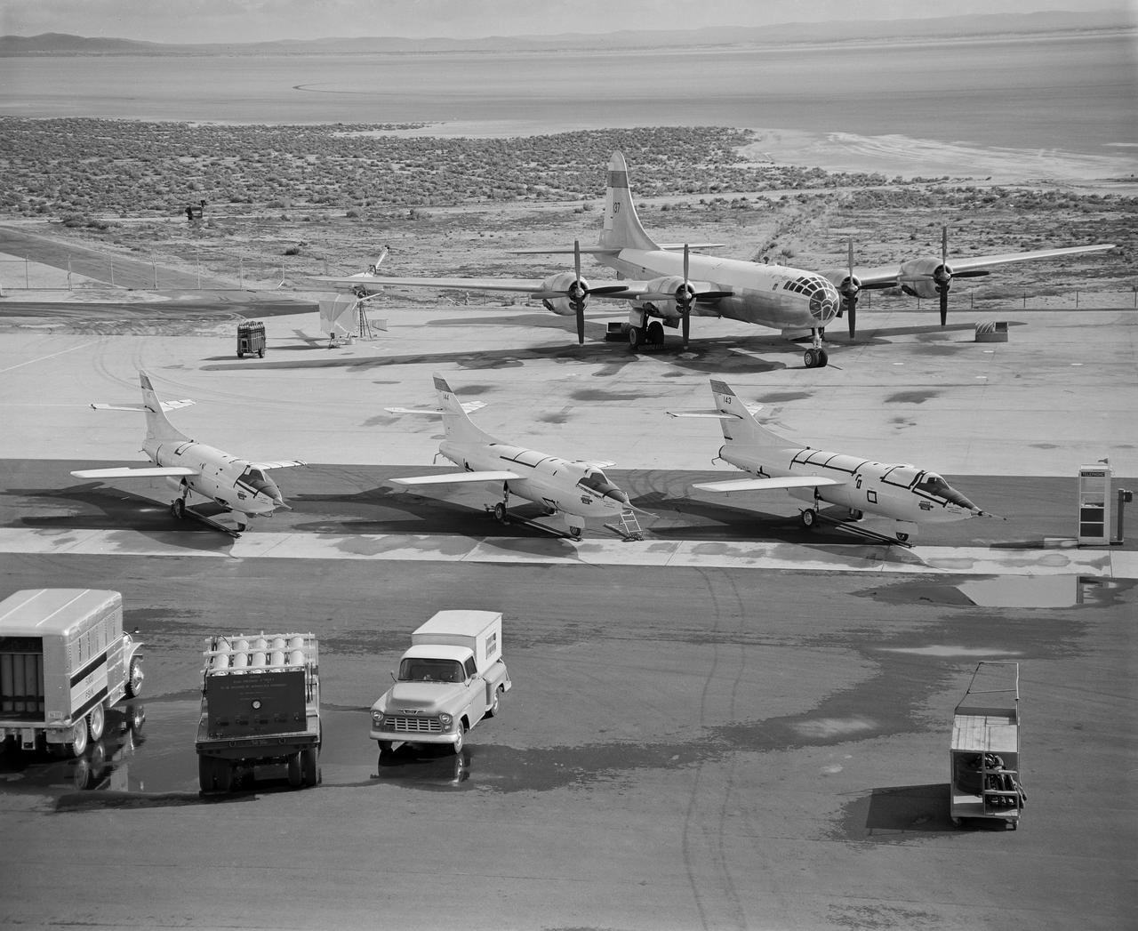
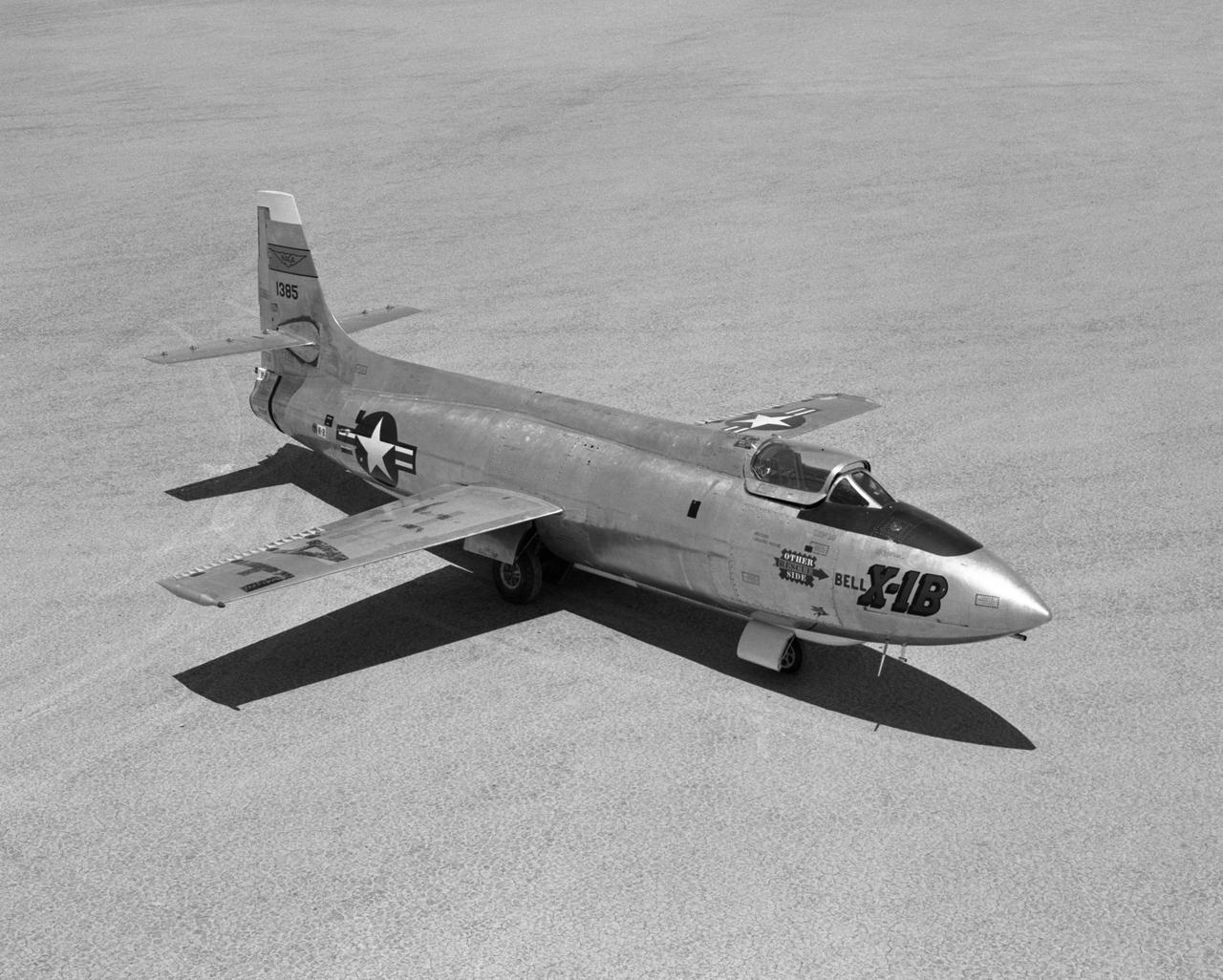
B-29 #800 with X-1B attached taxis in off of the lakebed.
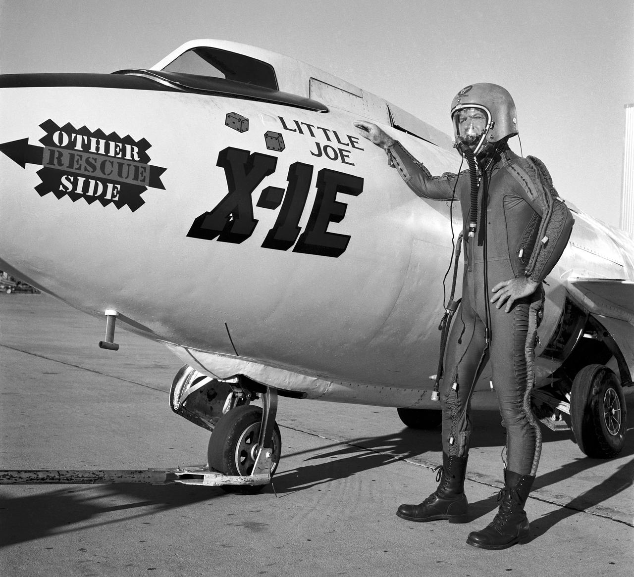
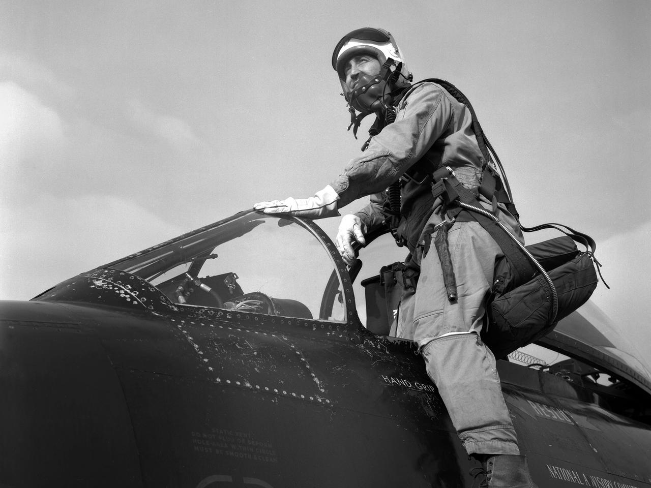
Joe Walker in a pressure suit beside the X-1E at the NASA High-Speed Flight Station, Edwards,California. The dice and "Little Joe" are prominently displayed under the cockpit area. (Little Joe is a dice players slang term for two deuces.) Walker is shown in the photo wearing an early Air Force partial pressure suit. This protected the pilot if cockpit pressure was lost above 50,000 feet. Similar suits were used in such aircraft as B-47s, B-52s, F-104s, U-2s, and the X-2 and D-558-II research aircraft. Five years later, Walker reached 354,200 feet in the X-15. Similar artwork - reading "Little Joe the II" - was applied for the record flight. These cases are two of the few times that research aircraft carried such nose art.
Local for Hypersonic Continuous Flow Facility
A 1/10th Scale Model of the X-15 research plane is prepared in Langley's 7 x 10 Foot Wind Tunnel for studies relating to spin characteristics. -- Photograph published in Winds of Change, 75th Anniversary NASA publication (page 66), by James Schultz.
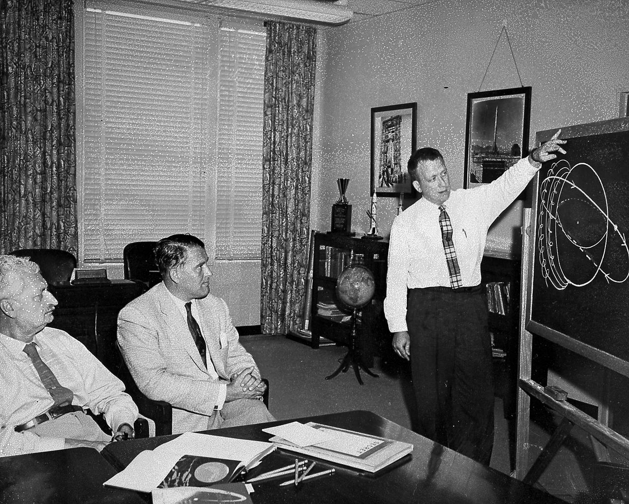
Professor Hermann Oberth and Dr. von Braun are briefed on satellite orbits by Dr. Charles A. Lundquist at Army Ballistic Missile Agency, Redstone Arsenal, Huntsville, Alabama.
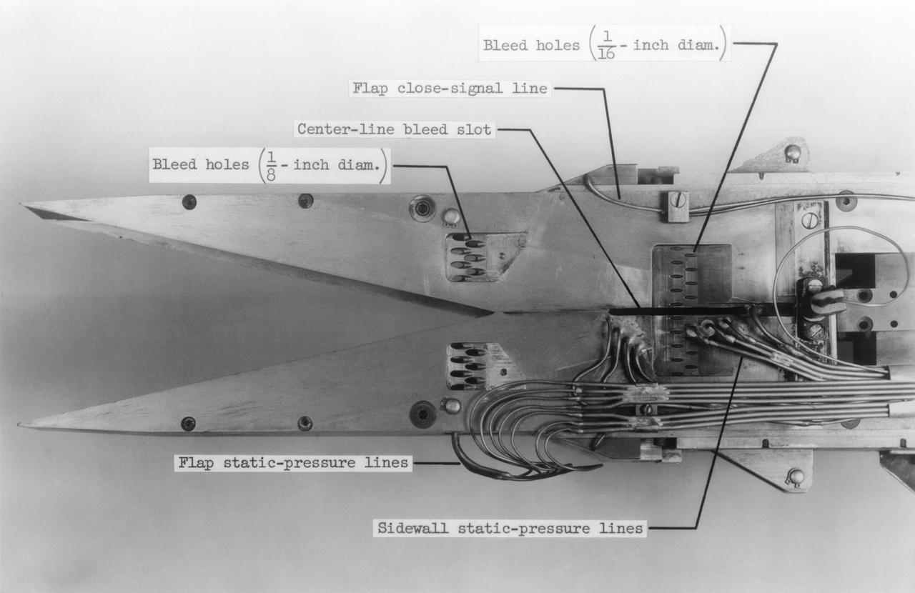
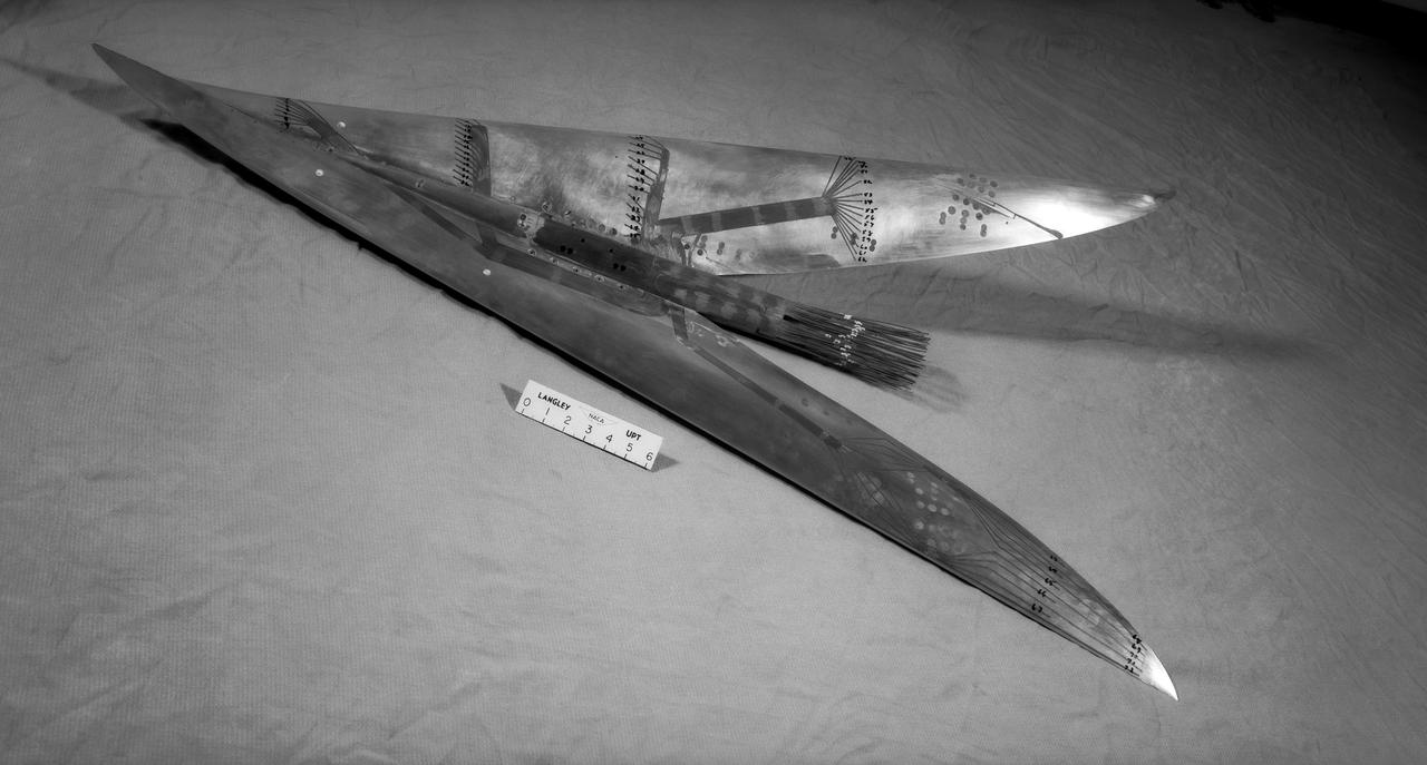
Mach number 6.9 Inlet. These negatives in jackets also: L-1958-2984.1 Figure 3b cone in NASA document L-1643 L-1958-2980.1 Figures 3a in document L-1643 declassified from Confidential
WS-110A Brown Bomber in Unitary Wind Tunnel Low Mach Number Test
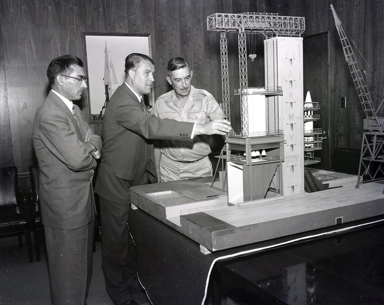
(From left to right) Karl L. Heimburg, Director of the Test Laboratory; Dr. Wernher von Braun, Director of the Development Operation Division; and Major General John B. Medaris with the model of S-1B Test Stand. Gen. Medaris was a Commander of the Army Ballistic Missile Agency (ABMA) in Redstone Arsenal, Alabama, during 1955 to 1958.
Brown Arrow Wing Bomber

WS-110A Brown Bomber in Unitary Wind Tunnel Low Mach Number Test

Atmosphere entry simulator
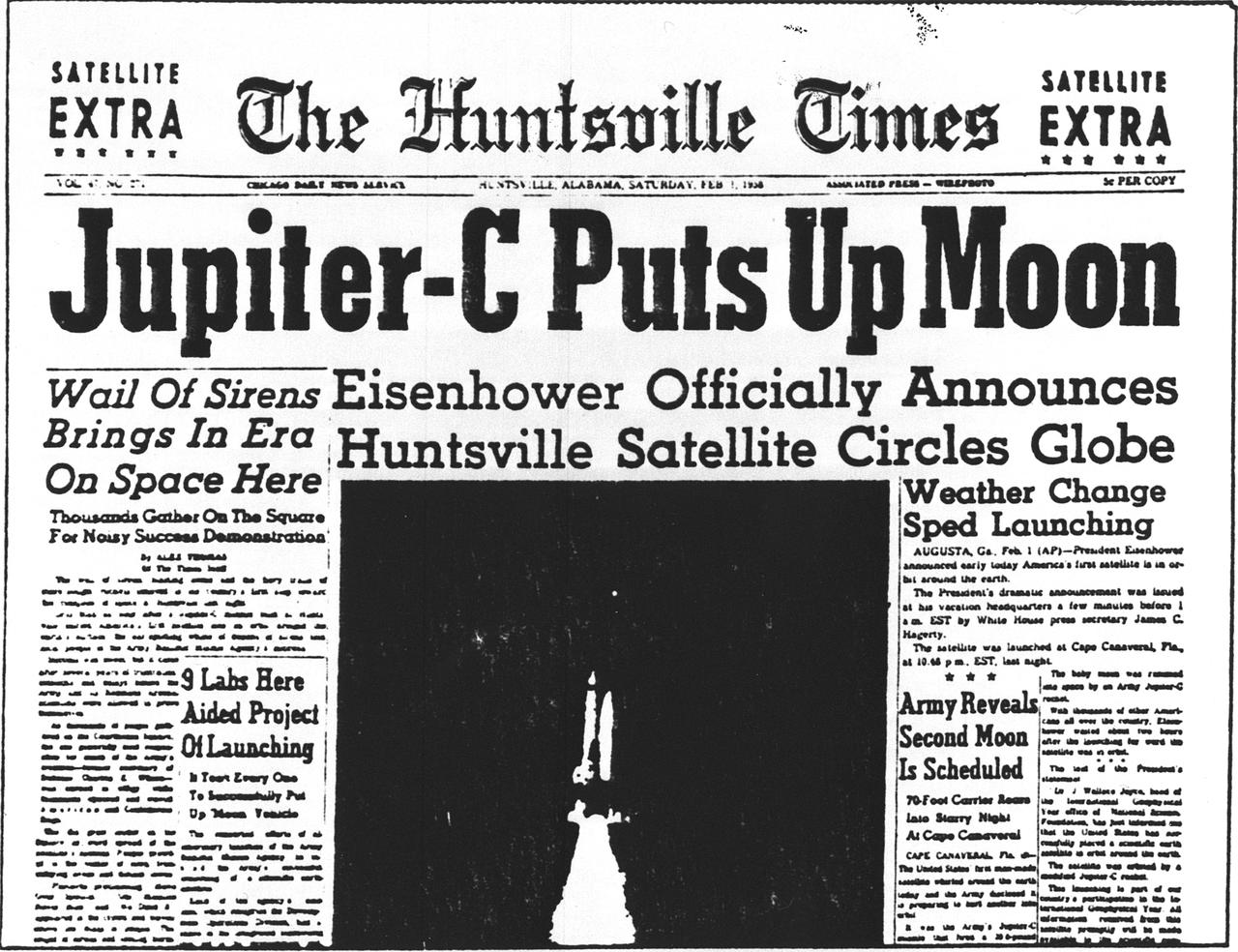
In January 1958, a modified Redstone rocket lifted the first American satellite into orbit just 3 months after the the von Braun team received the go-ahead. This modified Redstone rocket was known as a Jupiter-C. Its satellite payload was called Explorer I.
KENNEDY SPACE CENTER, FLA. -- Explorer I launched Jan. 31, 1958.
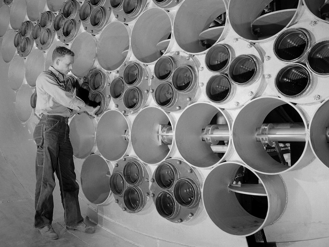
The 10- by 10-Foot Supersonic Wind Tunnel at the NACA Lewis Flight Propulsion Laboratory was built under the Congressional Unitary Plan Act which coordinated wind tunnel construction at the NACA, Air Force, industry, and universities. The 10- by 10, which began operation in 1956, was the largest of the three NACA tunnels built under the act. Researchers could test engines up to five feet in diameter in the 10- by 10-foot test section. A 250,000-horsepower axial-flow compressor fan can generate airflows up to Mach 3.5 through the test section. The incoming air must be dehumidified and cooled so that the proper conditions are present for the test. A large air dryer with 1,890 tons of activated alumina soaks up 1.5 tons of water per minute from the airflow. A cooling apparatus equivalent to 250,000 household air conditioners is used to cool the air. The air heater is located just upstream from the test section. Natural gas is combusted in the tunnel to increase the air temperature. The system could only be employed when the tunnel was run in its closed-circuit propulsion mode.
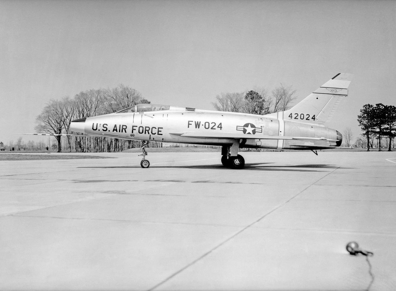
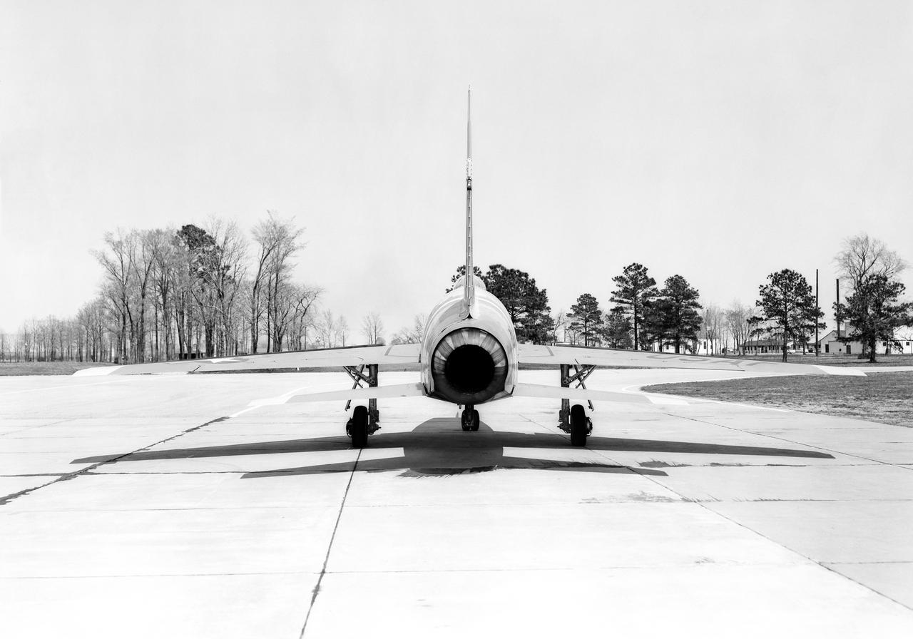
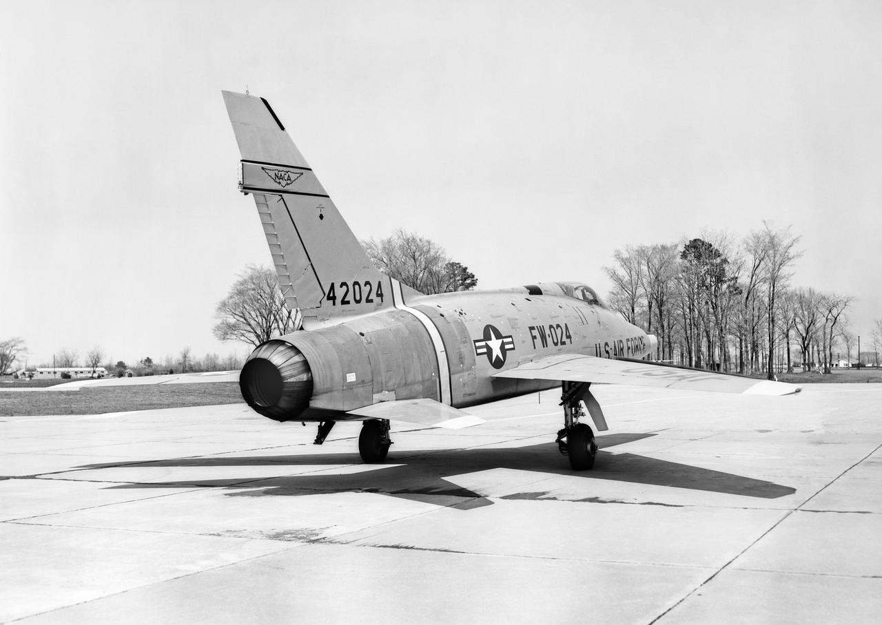
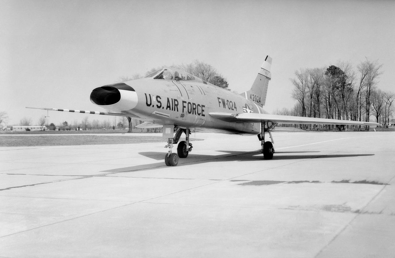
North American F-100 C airplane used in sonic boom investigation at Wallops, October 7, 1958. Photograph published in: A New Dimension Wallops Island Flight Test Range: The First Fifteen Years by Joseph Shortal. A NASA publication. Page 672. -- Aircraft number: NACA 42024. Side view, 3/4 view from front, 3/4 view from rear, rear view, and two front views.

B-29 #800 with X-1B attached taxi's in off of the lakebed.
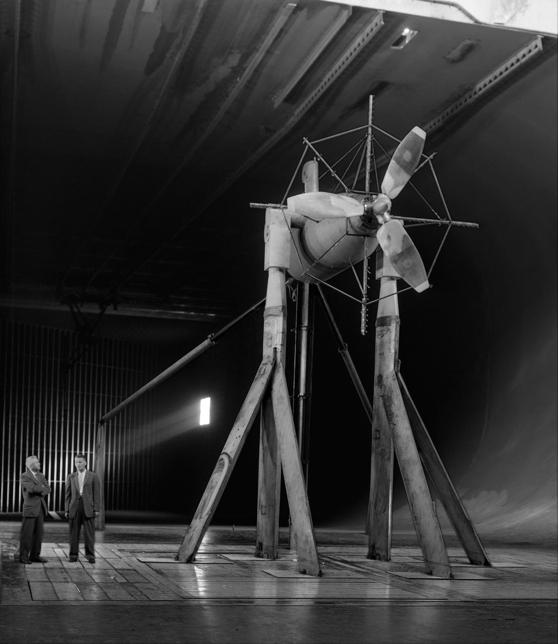
Investigation of cambered propeller design for VTOL/STOL airplane. 3/4 front view of Curtis VTOL propeller.
Behind three Douglas D-558-IIs is the B-29 launch aircraft. Under its right wing is the world’s first ground-based reaction control system motion simulator.
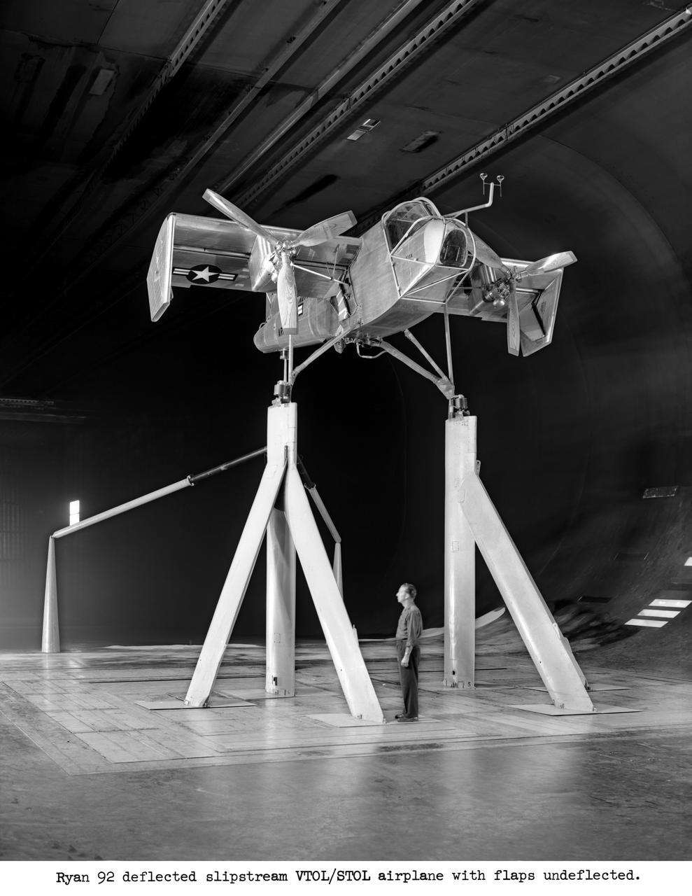
Ryan #92 deflected slipstream VTOL/STOL airplane with flaps undeflected.
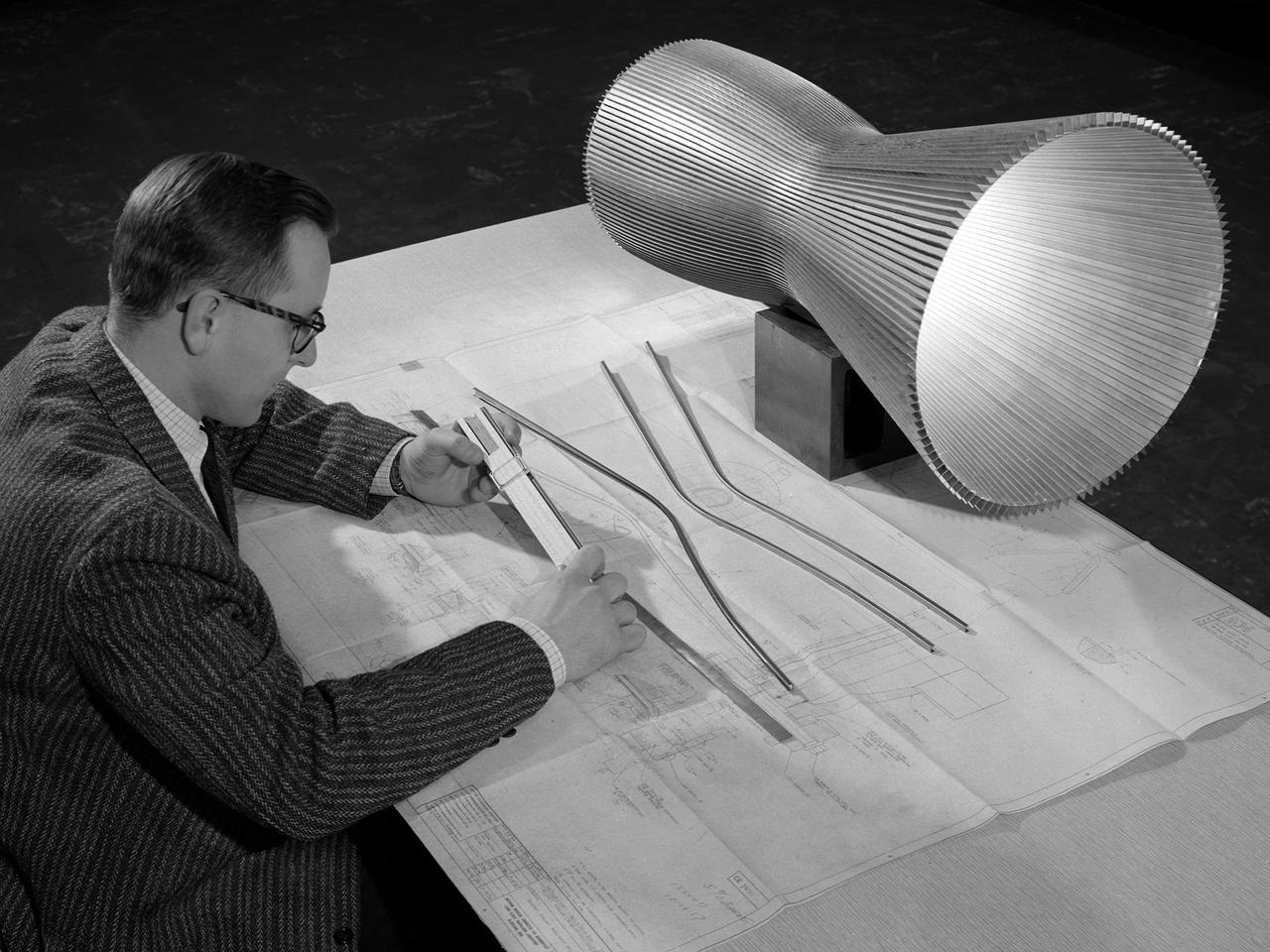
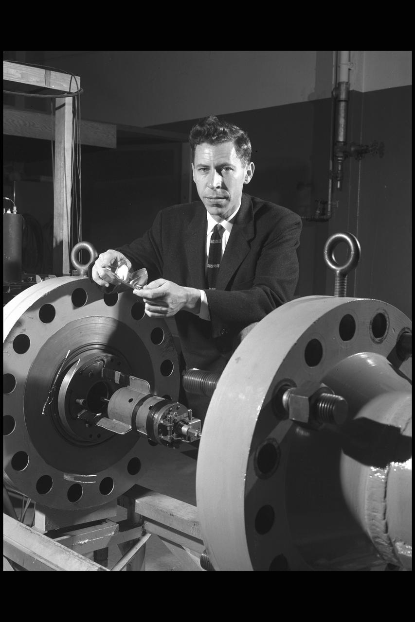
An engineer at the National Aeronautics and Space Administration (NASA) Lewis Research Center examines a drawing showing the assembly and details of a 20,000-pound thrust regeneratively cooled rocket engine. The engine was being designed for testing in Lewis’ new Rocket Engine Test Facility, which began operating in the fall of 1957. The facility was the largest high-energy test facility in the country that was capable of handling liquid hydrogen and other liquid chemical fuels. The facility’s use of subscale engines up to 20,000 pounds of thrust permitted a cost-effective method of testing engines under various conditions. The Rocket Engine Test Facility was critical to the development of the technology that led to the use of hydrogen as a rocket fuel and the development of lightweight, regeneratively-cooled, hydrogen-fueled rocket engines. Regeneratively-cooled engines use the cryogenic liquid hydrogen as both the propellant and the coolant to prevent the engine from burning up. The fuel was fed through rows of narrow tubes that surrounded the combustion chamber and nozzle before being ignited inside the combustion chamber. The tubes are visible in the liner sitting on the desk. At the time, Pratt and Whitney was designing a 20,000-pound thrust liquid-hydrogen rocket engine, the RL-10. Two RL-10s would be used to power the Centaur second-stage rocket in the 1960s. The successful development of the Centaur rocket and the upper stages of the Saturn V were largely credited to the work carried out Lewis.
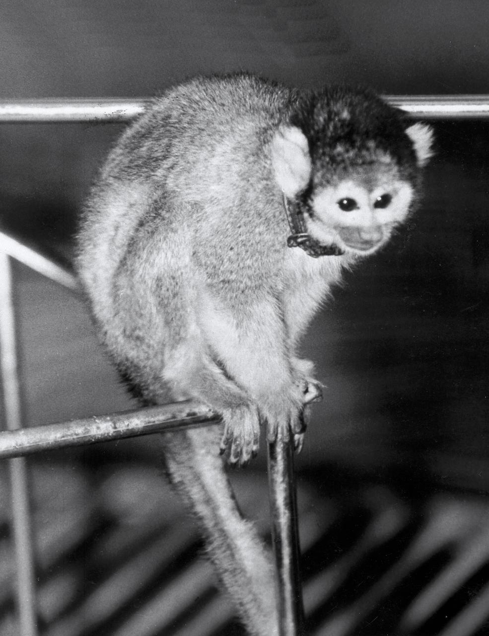
On May 28, 1958, Jupiter Intermediate Range Ballistic Missile provided by U.S. Army team in Huntsville, Alabama, launched a nose cone carrying Baker, a South American squirrel monkey and Able, an American-born rhesus monkey. Baker, pictured here and commonly known as "Miss Baker", was later given a home at the U.S. Space and Rocket Center until her death on November 29, 1984. Able died in 1958. (Photo - Courtesy of Huntsville/Madison County Public Library)
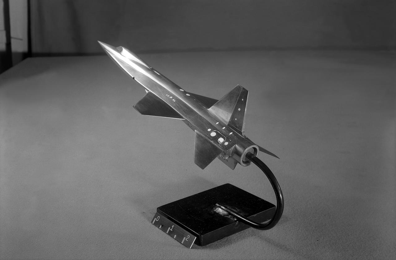
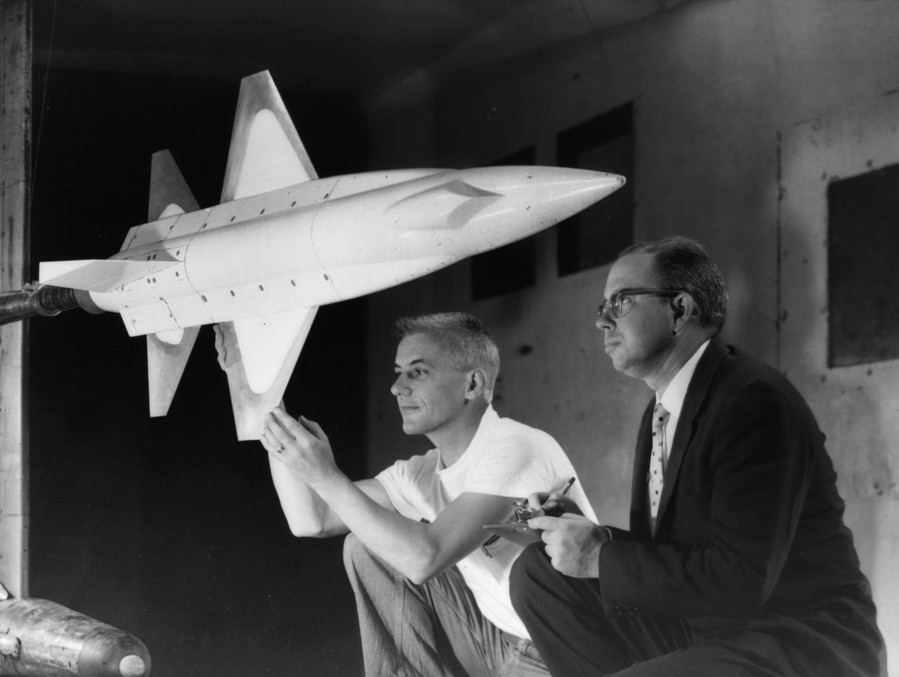
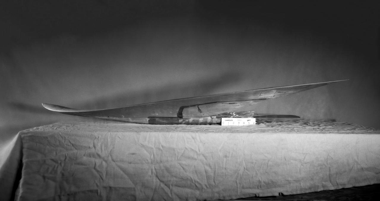
This scale-model of North American's initial X-15 design was tested in North American and NACA wind tunnels note the conventional tail and fuselage side-tunnels that extend far toward the aircraft nose. North American engineers would determine that the variable wedge-angle stabilizer created a weight issue, and aeronautical testing by Langley engineers confirmed that the side-tunnels made the design less stable.
North American F-100A NASA-200 Super Sabre airplane - wing leading edge deflected 60 degrees for increased lift with boundary=layer control; takeoff preformance was improved 10% (mar 1960)

Photographed on: 12 09 58. -- Mercury capsule details, capsule in cargo bay of C-130 airplane prior to drop test, equipment in C130 for doing drop test.
Bell X-1B fitted with a reaction control system on the lakebed
Explorer 1 satellite. This photo was taken during the installation of Explorer-1, the first United States' Earth-orbiting satellite, to its launch vehicle, Jupiter-C, in January 1958
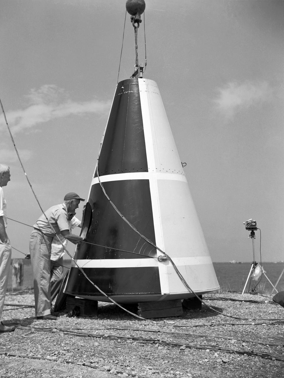
Photographed on: 08 05 1958. -- Impact test conducted by Langley's Hydrodynamics Division. The Division conducted a series of impact studies with full scale and model capsules of the original capsule shape A. Joseph Shortal wrote (Vol. 3, p. 16): The basic design of the capsule was made by M.A. Faget and his coworkers at PARD during the winter of 1957-1958. It was natural, then, that extensive use was made of the facilities at Wallops during the development of the spacecraft. The tests at Wallops consisted of 26 full-size capsules, either launched from the ground by rocket power or dropped from airplanes at high altitude and 28 scaled models, either rocket boosted or released from balloons. Emphasis in the Wallops program was on dynamic stability and aerodynamic heating of the capsule, and effectiveness of the pilot-escape and parachute-recovery systems. The biggest part of the Wallops program was the series of full-size capsules, rocket launched with the Little Joe booster, developed especially for Mercury. -- Published in Joseph A. Shortal, History of Wallops Station: Origins and Activities Through 1949, (Wallops Island, VA: National Aeronautics and Space Administration, Wallops Station, nd), Comment Edition.

A Republic F-84 Thunderjet dramatically modified at the NASA Lewis Research Center to investigate the use of slotted nozzles to reduce exhaust noise. The F-84 was a single-seat fighter-bomber powered by an Allison J35 turbojet. It was the Air Force’s first post-World War II tactical aircraft and was used extensively in the Korean War. The laboratory had acquired the aircraft in 1954 and modified it in order to demonstrate the reverse thruster. The tail end of the aircraft was then removed for a series of large nozzle investigations. Lewis researchers launched an extensive program in the mid-1950s to develop methods of reducing engine noise as the airline industry was preparing to introduce the first turbojet-powered passenger aircraft. The early NACA investigations determined that the primary source of noise was the mixing of the engine’s hot exhaust with the cool surrounding air. Lewis researchers studied many different nozzles designed to facilitate this mixing. Nozzles with elongated exit sections, as seen in this photograph, produced lower noise levels. These long slot nozzles were also considered for Short Take-off and Landing aircraft because their long flat surfaces provided lift. In 1958 Lewis tested several full-scale slot nozzles on the F-84. The researchers, led by Willard Cole, sought to determine the noise-generation characteristics for nozzles having large a width-to-height ratio. The nozzle in this photograph has a 100 to 1 width-to-height ratio. Cole determined that the experimental nozzles produced the same levels of sound as the standard nozzle, but the changes in the directional noise were substantial.
North American F-100 C airplane used in sonic boom investigation at Wallops, October 7, 1958. Photograph published in: A New Dimension Wallops Island Flight Test Range: The First Fifteen Years by Joseph Shortal. A NASA publication. Page 672. -- Aircraft number: NACA 42024. Side view, 3/4 view from front, 3/4 view from rear, rear view, and two front views.
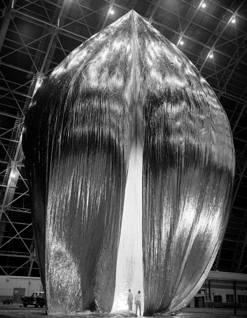
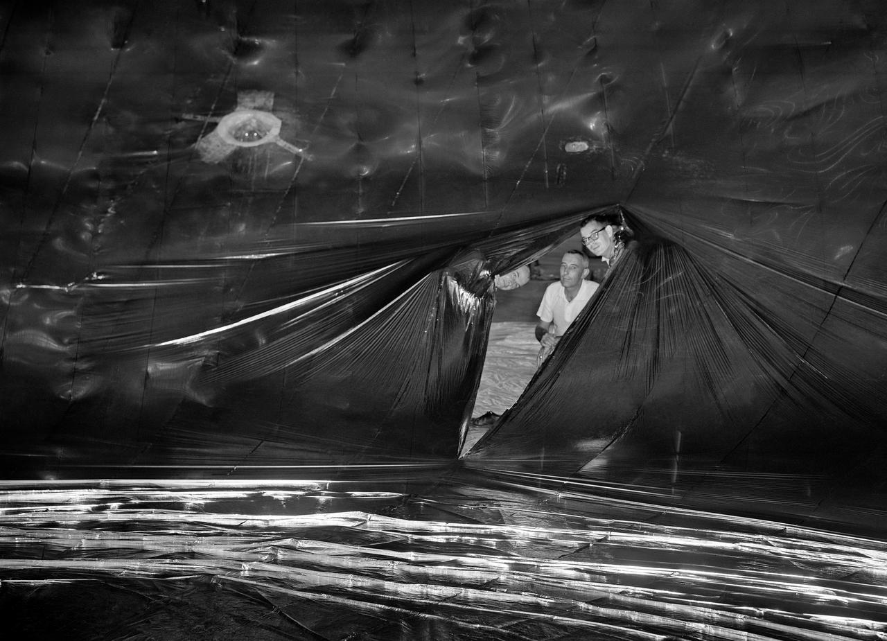
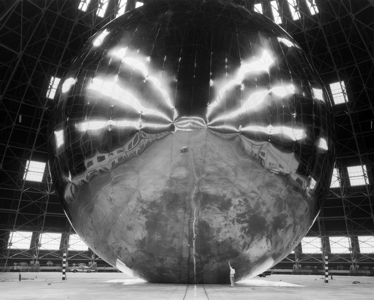
Inflation Tests of the Echo 1 Satellite in Weeksville, N.C. 1958-L-03603 Image Langley engineers Edwin Kilgore (center), Norman Crabill (right) and an unidentified man take a peek inside the vast balloon during inflation tests. Page. 183 Space Flight Revolution NASA Langley Research Center From Sputnik to Apollo. NASA SP-4308.
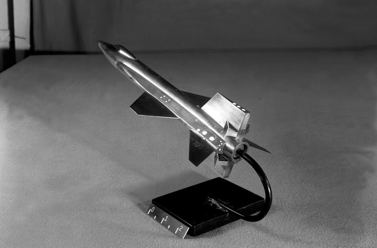
This scale-model of North American's initial X-15 design was tested in North American and NACA wind tunnels note the conventional tail and fuselage side-tunnels that extend far toward the aircraft nose. North American engineers would determine that the variable wedge-angle stabilizer created a weight issue, and aeronautical testing by Langley engineers confirmed that the side-tunnels made the design less stable.
Investigation of cambered propeller design for VTOL/STOL airplane. 3/4 front view of complete configuration, 0 deg.
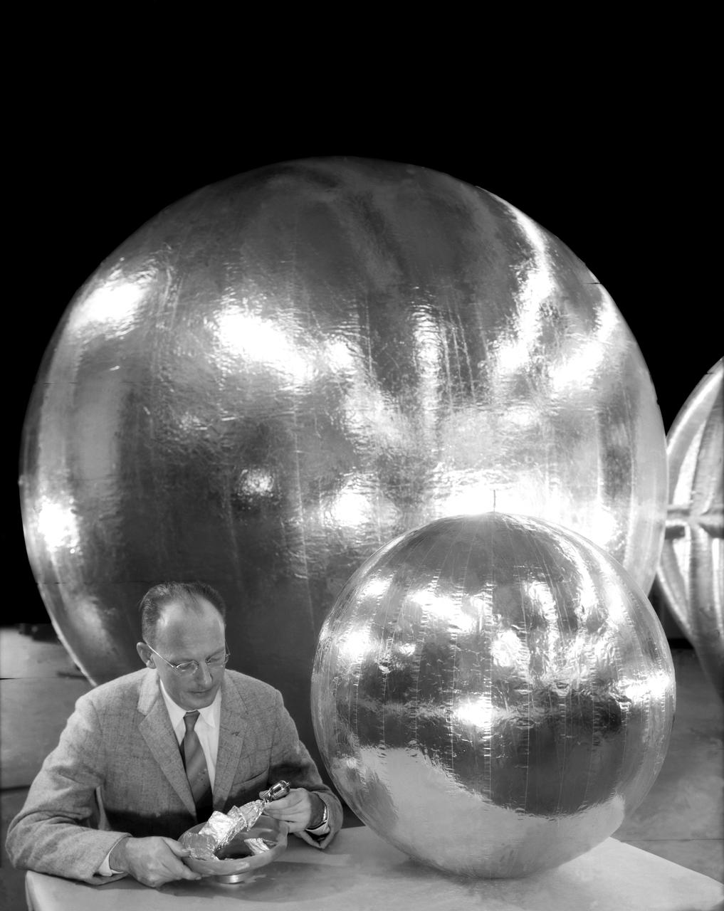
William J. O Sullivan at desk with folded subsatellite, 30 inch subsatellite, 12 foot subsatellite, and corner reflector.
North American F-100 C airplane used in sonic boom investigation at Wallops, October 7, 1958. Photograph published in: A New Dimension Wallops Island Flight Test Range: The First Fifteen Years by Joseph Shortal. A NASA publication. Page 672. -- Aircraft number: NACA 42024. Side view, 3/4 view from front, 3/4 view from rear, rear view, and two front views.
NACA Photographer John F Parsons, Ames Assistant Director

Launch of Jupiter-C/Explorer 1 at Cape Canaveral, Florida on January 31, 1958. After the Russian Sputnik 1 was launched in October 1957, the launching of an American satellite assumed much greater importance. After the Vanguard rocket exploded on the pad in December 1957, the ability to orbit a satellite became a matter of national prestige. On January 31, 1958, slightly more than four weeks after the launch of Sputnik.The ABMA (Army Ballistic Missile Agency) in Redstone Arsenal, Huntsville, Alabama, in cooperation with the Jet Propulsion Laboratory, launched a Jupiter from Cape Canaveral, Florida. The rocket consisted of a modified version of the Redstone rocket's first stage and two upper stages of clustered Baby Sergeant rockets developed by the Jet Propulsion Laboratory and later designated as Juno boosters for space launches
North American F-100 C airplane used in sonic boom investigation at Wallops, October 7, 1958. Photograph published in: A New Dimension Wallops Island Flight Test Range: The First Fifteen Years by Joseph Shortal. A NASA publication. Page 672. -- Aircraft number: NACA 42024. Side view, 3/4 view from front, 3/4 view from rear, rear view, and two front views.
Inflation Tests of the Echo 1 Satellite in Weeksville, N.C. 1958-L-03603 Image Langley engineers Edwin Kilgore (center), Norman Crabill (right) and an unidentified man take a peek inside the vast balloon during inflation tests. Page. 183 Space Flight Revolution NASA Langley Research Center From Sputnik to Apollo. NASA SP-4308.
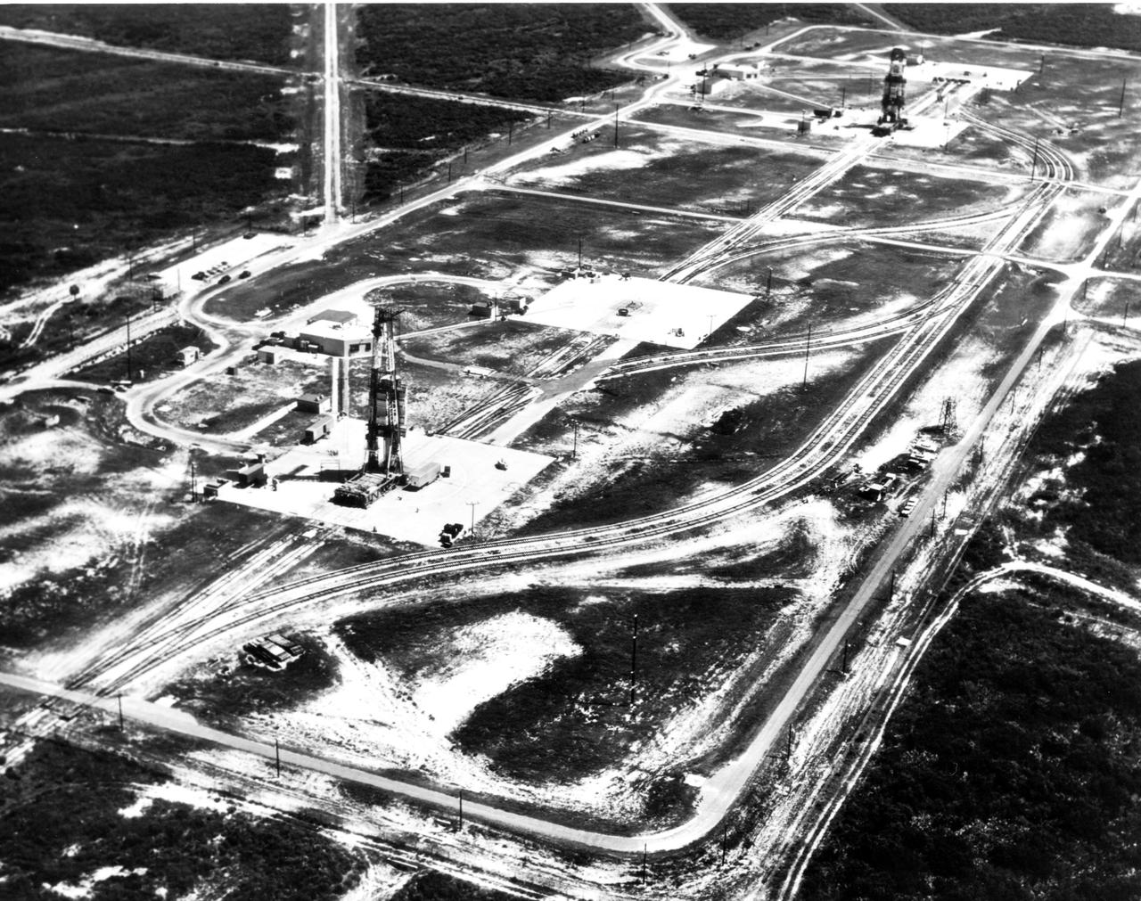
KENNEDY SPACE CENTER, FLA. - This view shows the launch pad that Explorer 1 launched from in 1958.
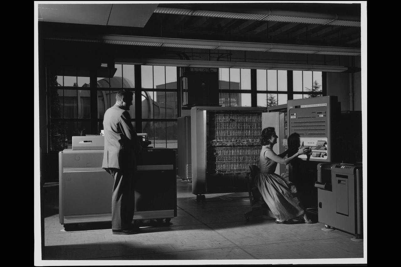
Electronic Machine Computing Branch, 704 computing lab; (left - right) William A Mersman and Marcelline K Chartz (aka - Marcie Smith) with IBM 704 Date Processor
Wood Mock-up of Arrow- Wing Bomber to Show Wing Contours
Echo Satellite

William J. O Sullivan at desk with folded subsatellite, 30 inch subsatellite, 12 foot subsatellite, and corner reflector.
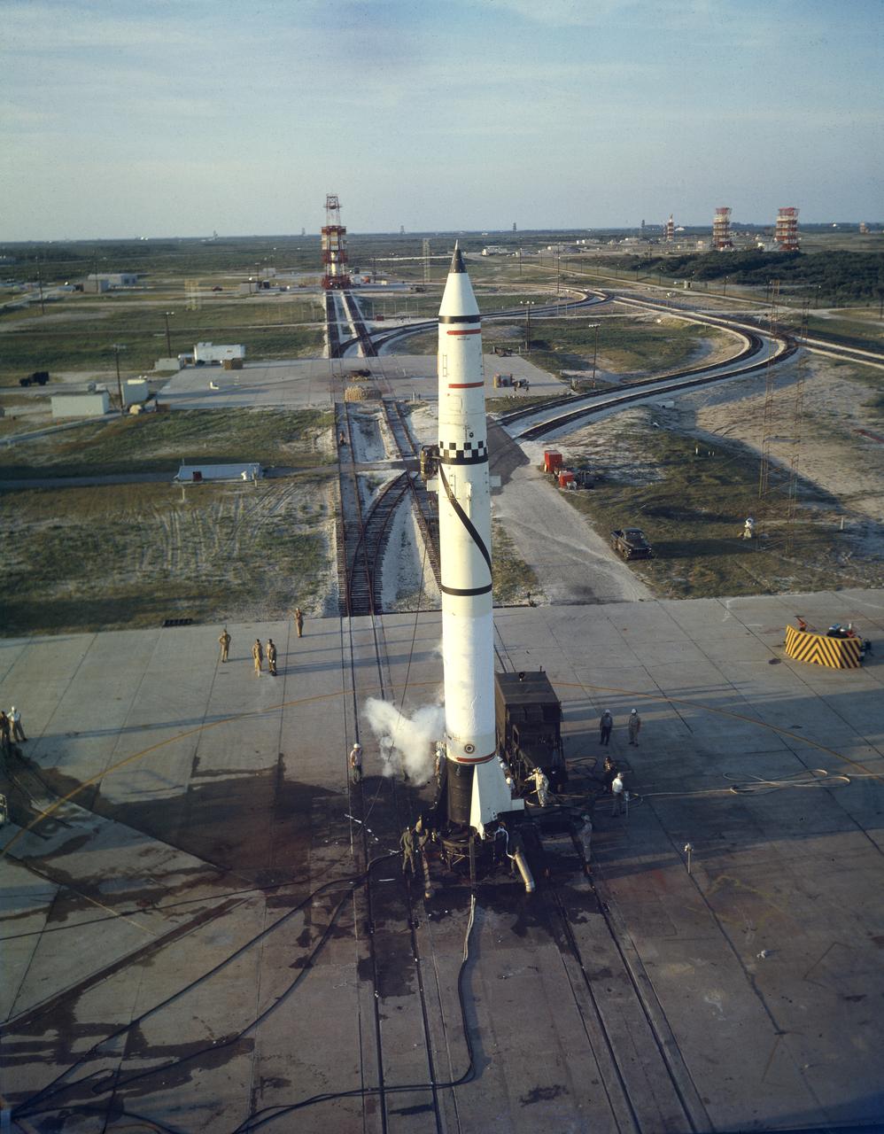
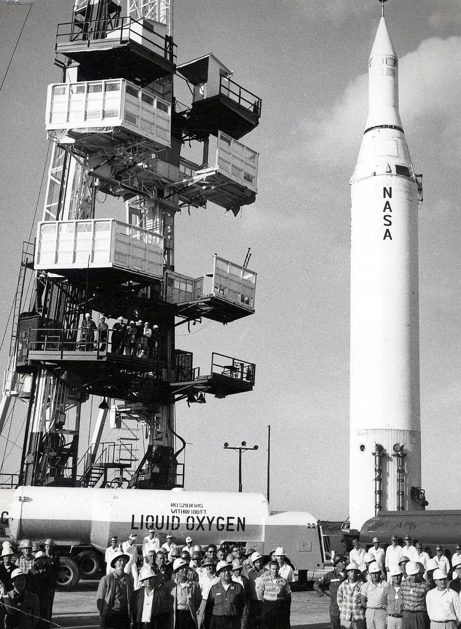
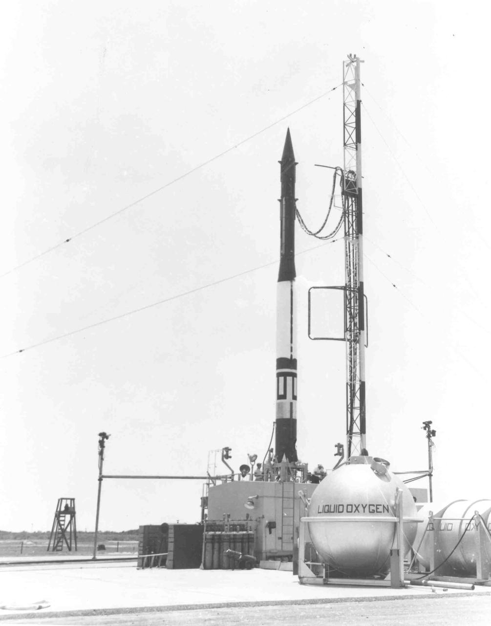
Redstone missile No. 1002 on the launch pad at Cape Canaveral, Florida, on May 16, 1958. The Redstone ballistic missile was a high-accuracy, liquid-propelled, surface-to-surface missile developed by the Army Ballistic Missile Agency, Redstone Arsenal, in Huntsville, Alabama, under the direction of Dr. von Braun. The Redstone engine was a modified and improved version of the Air Force's Navaho cruise missile engine of the late forties. The A-series, as this would be known, utilized a cylindrical combustion chamber as compared with the bulky, spherical V-2 chamber. By 1951, the Army was moving rapidly toward the design of the Redstone missile, and production was begun in 1952. Redstone rockets became the "reliable workhorse" for America's early space program. As an example of the versatility, Redstone was utilized in the booster for Explorer 1, the first American satellite, with no major changes to the engine or missile
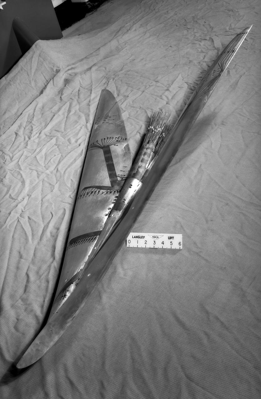
Brown Arrow Wing Bomber
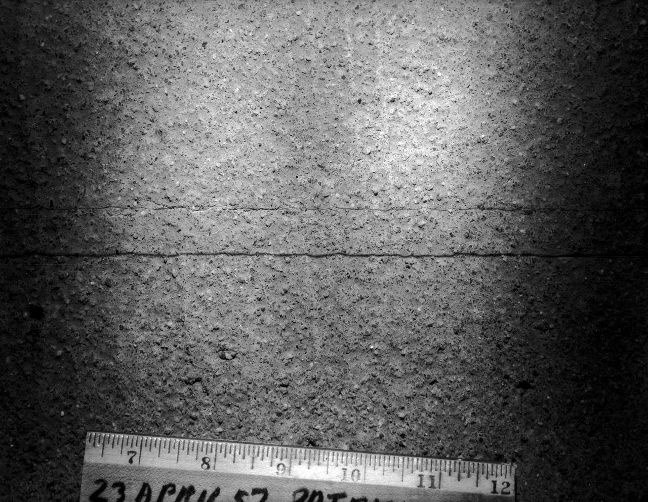
Runway surface Patrick Henry Airport April 23, 1957
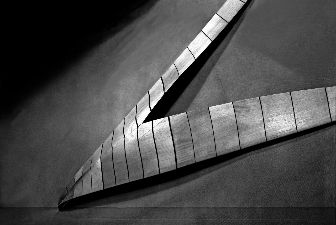
Wood Mock-up of Arrow- Wing Bomber to Show Wing Contours
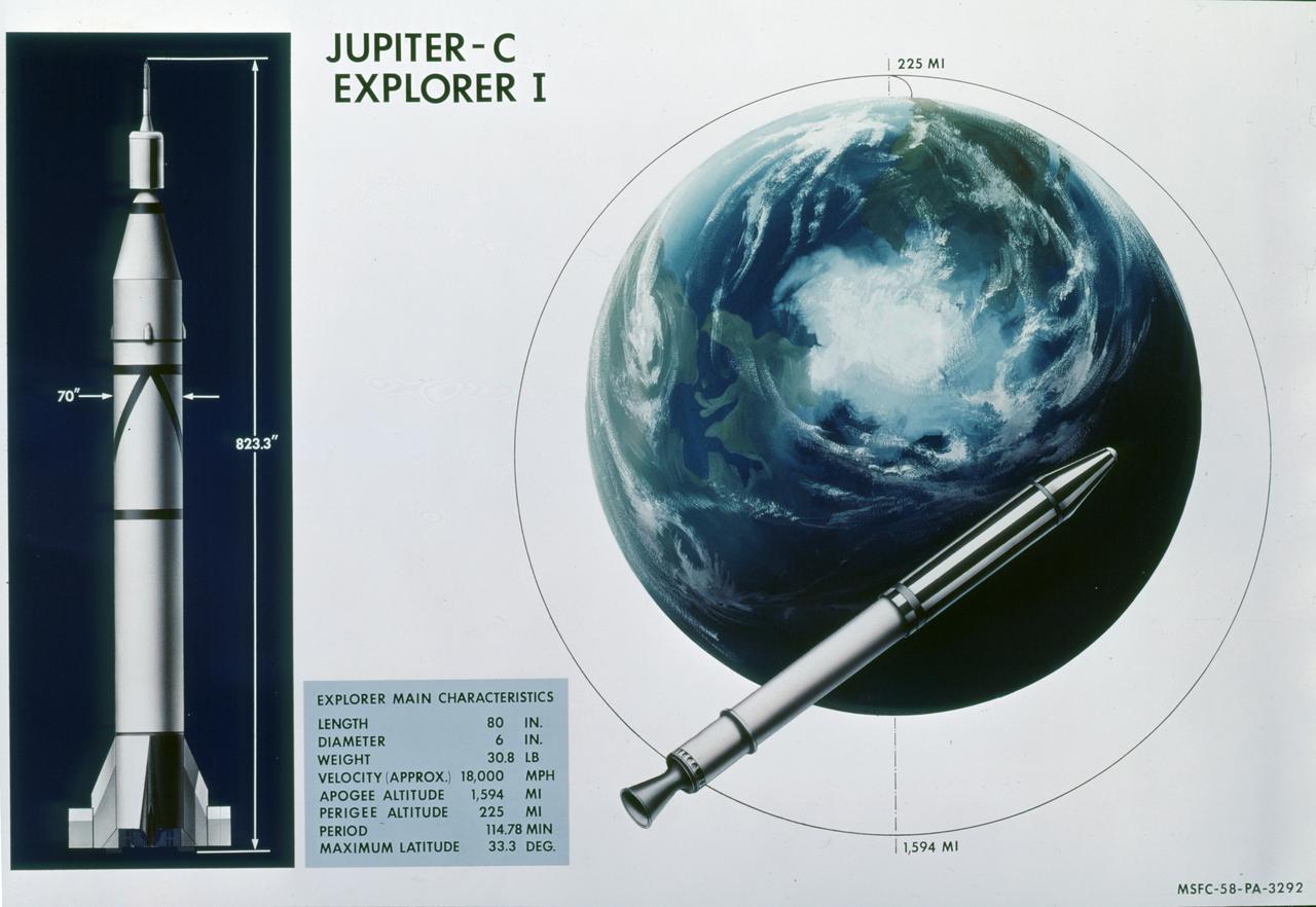
This illustration shows the main characteristics of the Jupiter C launch vehicle and its payload, the Explorer I satellite. The Jupiter C, America's first successful space vehicle, launched the free world's first scientific satellite, Explorer 1, on January 31, 1958. The four-stage Jupiter C measured almost 69 feet in length. The first stage was a modified liquid fueled Redstone missile. This main stage was about 57 feet in length and 70 inches in diameter. Fifteen scaled down SERGENT solid propellant motors were used in the upper stages. A "tub" configuration mounted on top of the modified Redstone held the second and third stages. The second stage consisted of 11 rockets placed in a ring formation within the tub. Inserted into the ring of second stage rockets was a cluster of 3 rockets making up the third stage. A fourth stage single rocket and the satellite were mounted atop the third stage. This "tub", all upper stages, and the satellite were set spirning prior to launching. The complete upper assembly measured 12.5 feet in length. The Explorer I carried the radiation detection experiment designed by Dr. James Van Allen and discovered the Van Allen Radiation Belt.
WS-110A Brown Bomber in Unitary Wind Tunnel Low Mach Number Test
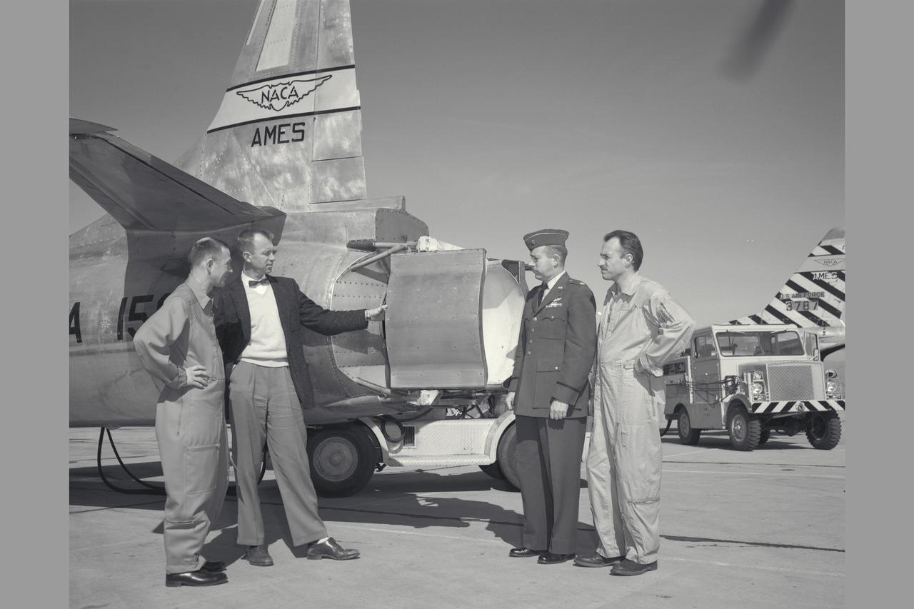
NACA Photographer Thrust reverser on F-94C-1 (AF50-956 NACA 156) Starfire (l to R) Air Force Major E. Sommerich; Ames Engineer Seth Anderson, Lt. Col. Tavasti; and Ames Chief test pilot George Cooper discussing phases of flight evaluation tests. Note: Used in publication in Flight Research at Ames; 57 Years of Development and Validation of Aeronautical Technology NASA SP-1998-3300 fig 91
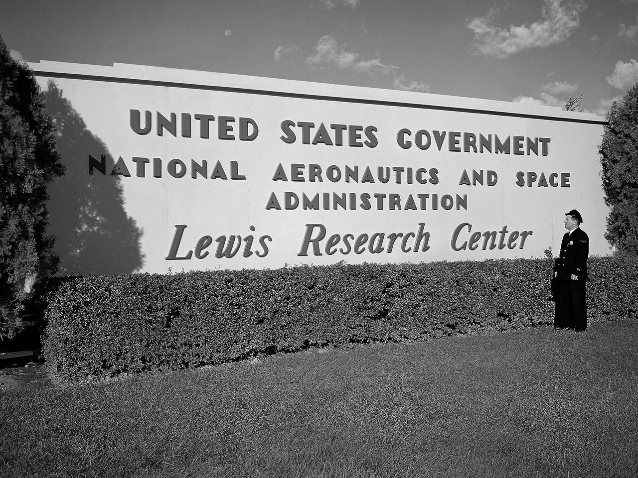
A security guard examines the new sign near the entrance to the Lewis Research Center one day after the National Aeronautics and Space Administration (NASA) was officially established. NASA came into being on October 1, 1958, and the National Advisory Committee for Aeronautics (NACA) Lewis Flight Propulsion Laboratory became the NASA Lewis Research Center. Lewis underwent a major reorganization and began concentrating its efforts almost exclusively on the space program. NACA Lewis researchers had been advocating further space research for years. As early as 1955, Lewis management urged the NACA expand its rocket engine research as a logical extension of its aircraft engine work. Lewis management claimed that space exploration was imperative for the nation’s survival during the Cold War. They called for an annual 25-percent increase in the NACA’s staff, a new space laboratory, a launching center, communications center, and other facilities. They were basically outlining what would be needed for the new space agency. During NASA’s first two years of existence, Lewis refocused its efforts almost completely on the space program. Less than 10 percent of the annual budget was dedicated to aeronautics. In the aftermath that followed President Kennedy’s April 1961 “Urgent Needs” address to Congress, NASA was given a seemingly unlimited budget. The Agency reorganized and began swelling its ranks through a massive recruiting effort to accomplish the accelerated lunar landing mission. Lewis personnel increased from approximately 2,700 in 1961 to over 4,800 in 1966.
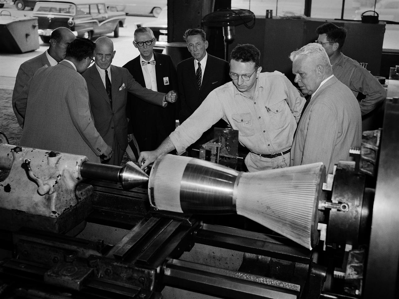
National Advisory Committee for Aeronautics (NACA) Chairman James Doolittle and Thompson Products Chairman of the Board Frederick Crawford receive a tour of the Lewis Flight Propulsion Laboratory during the last few months of the NACA. Lewis mechanic Leonard Tesar demonstrates the machining of a 20,000-pound thrust rocket engine for the group in the Fabrication Shop. From left to right, Associate Director Eugene Manganiello, researcher Edward Baehr, Doolittle, NACA Executive Secretary John Victory, Crawford, Tesar, Lewis Director Raymond Sharp, and mechanic Curtis Strawn. Doolittle began his career as a test pilot and air racer. In 1942 he famously flew a B-25 Mitchell on a daring raid over Tokyo. Doolittle also worked with the aviation industry on the development of aircraft fuels and instrumentation. After the war he served as vice president of Shell Oil and as a key government advisor. In this capacity he also served on the NACA’s Executive Committee for a number of years and served as its Chairman in 1957 and 1958. Tesar was a supervisor at the Sheet Metal Shop in the Fabrication Building. He joined the laboratory in 1948 and enrolled in their Apprentice Program. He graduated from the school three years later as an aviation metalsmith. The Fabrication Branch created a wide variety of hardware for the laboratory’s research projects. Requests from research divisions ranged from sheetmetal manufacturing for aircraft to fabrication of rocket engines. Tesar retired in 1982 after 37 years of service.
North American F-100 C airplane used in sonic boom investigation at Wallops, October 7, 1958. Photograph published in: A New Dimension Wallops Island Flight Test Range: The First Fifteen Years by Joseph Shortal. A NASA publication. Page 672. -- Aircraft number: NACA 42024. Side view, 3/4 view from front, 3/4 view from rear, rear view, and two front views.
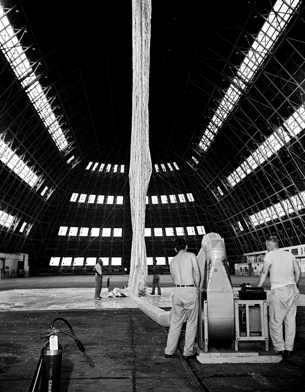
Inflation Tests of the Echo 1 Satellite in Weeksville, N.C. 1958-L-03603 Image Langley engineers Edwin Kilgore (center), Norman Crabill (right) and an unidentified man take a peek inside the vast balloon during inflation tests. Page. 183 Space Flight Revolution NASA Langley Research Center From Sputnik to Apollo. NASA SP-4308.
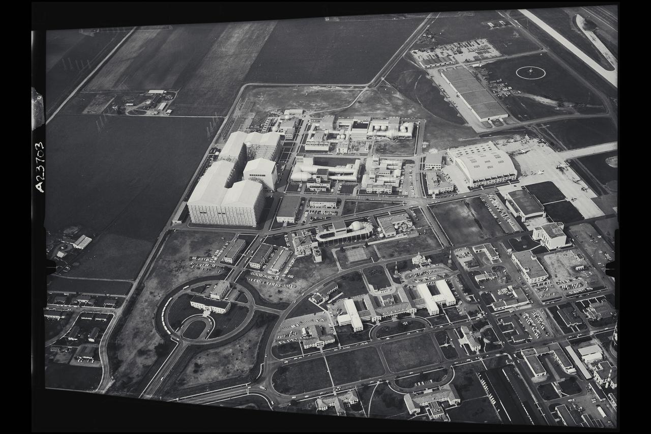
Aerial of Ames Aernautical Laboratory
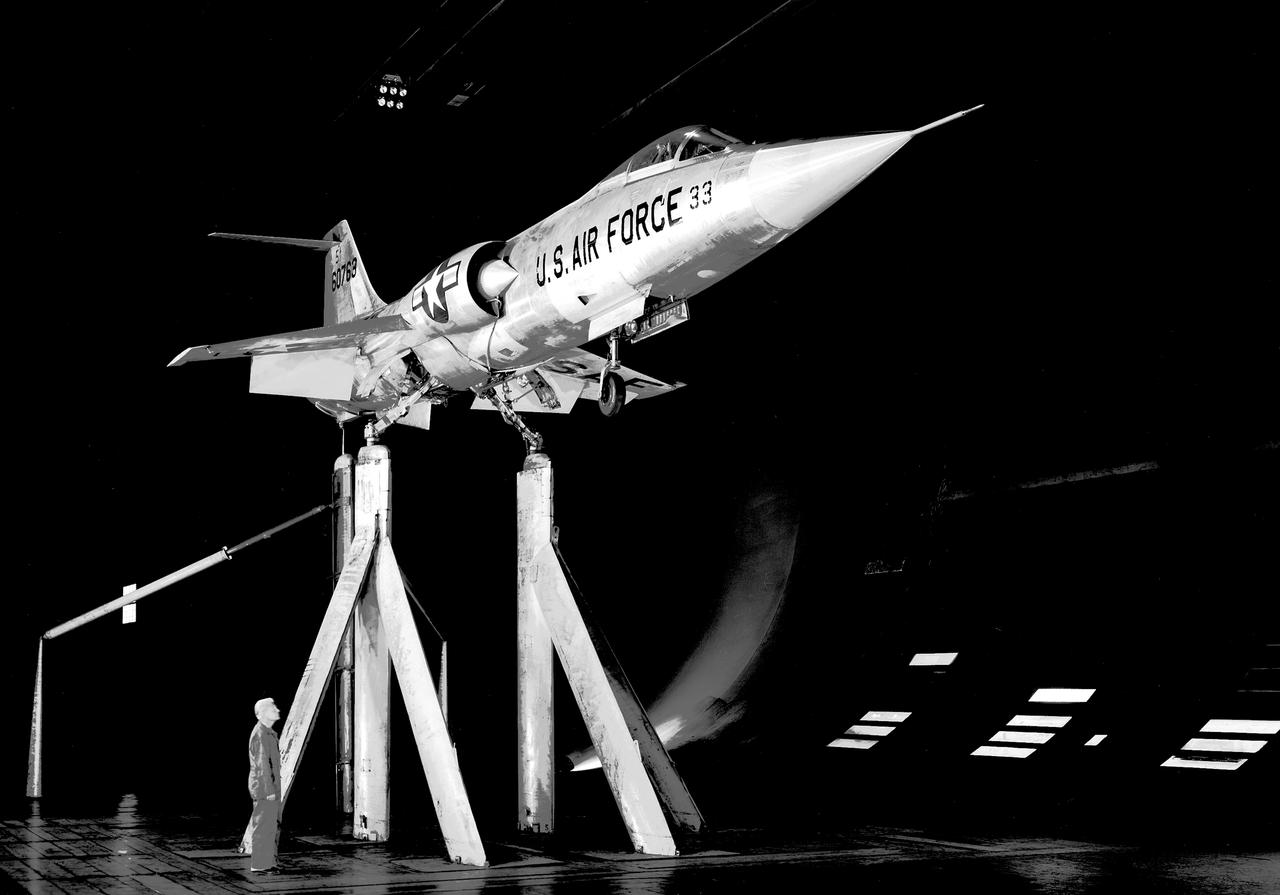
3/4 front view from below of Air Force F-104. The Lockheed F-104 Starfighter is a single-engine, supersonic interceptor aircraft originally developed by Lockheed for the United States Air Force (USAF). One of the Century Series of fighter aircraft, it was operated by the air forces of more than a dozen nations from 1958 to 2004.
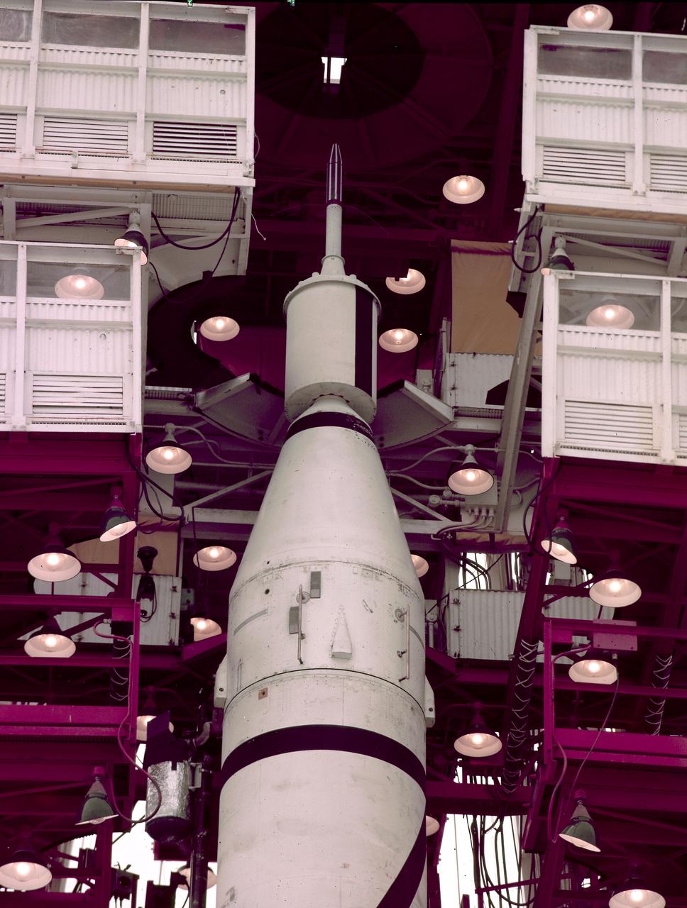
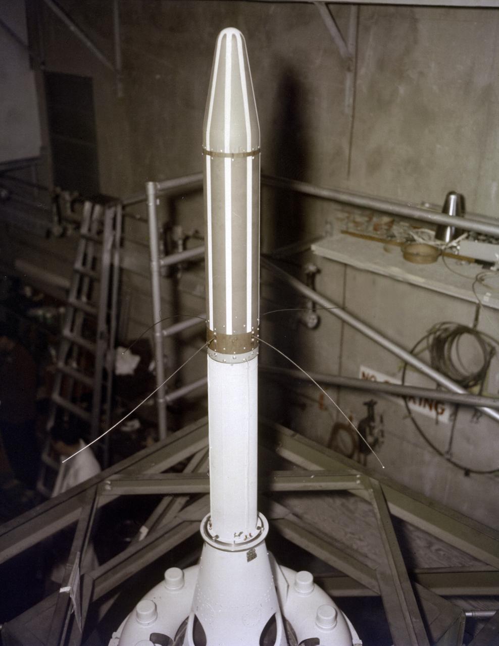
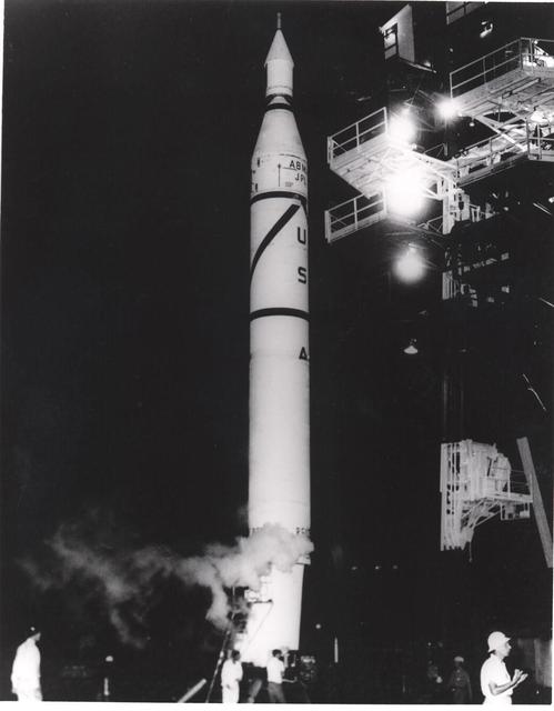
Explorer 1 atop a Jupiter-C in gantry. Jupiter-C carrying the first American satellite, Explorer 1, was successfully launched on January 31, 1958. The Jupiter-C launch vehicle consisted of a modified version of the Redstone rocket's first stage and two upper stages of clustered Baby Sergeant rockets developed by the Jet Propulsion Laboratory and later designated as Juno boosters for space launches
Juno I, a slightly modified Jupiter-C launch vehicle, shortly before the January 31, 1958 launch of America's first satellite, Explorer I. The Jupiter-C, developed by Dr. Wernher von Braun and the rocket team at Redstone Arsenal in Huntsville, Alabama, consisted of a modified version of the Redstone rocket's first stage and two upper stages of clustered Baby Sergeant rockets developed by the Jet Propulsion Laboratory.
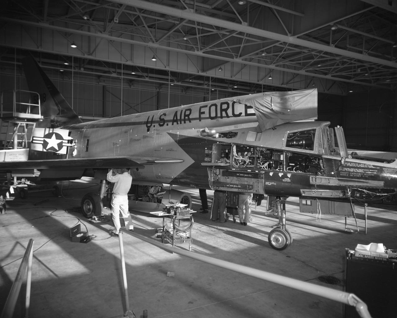
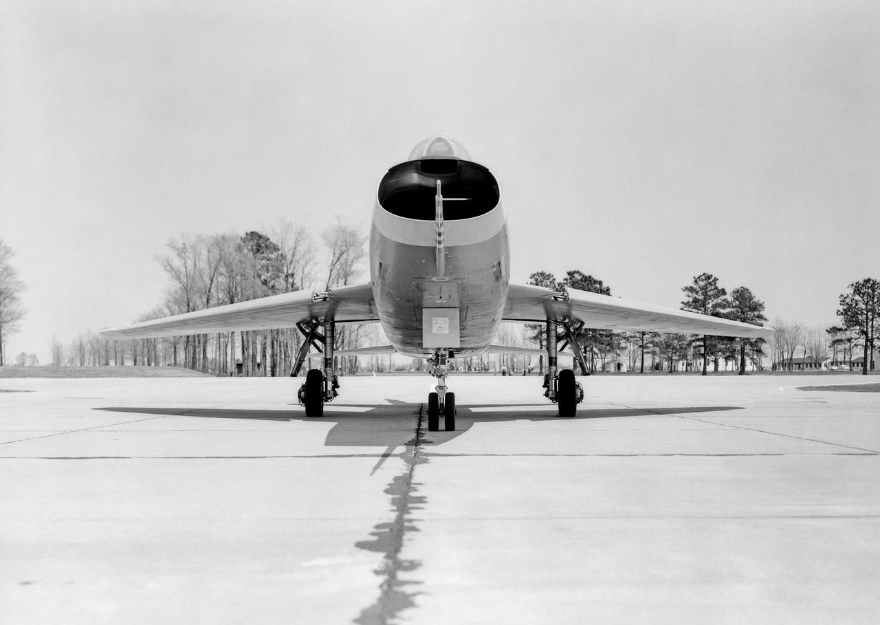
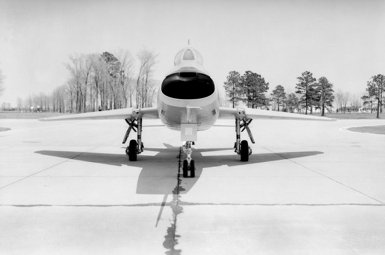
Maintanence on the first F-107A. Apr. 9, 1958
Brown Arrow Wing Bomber
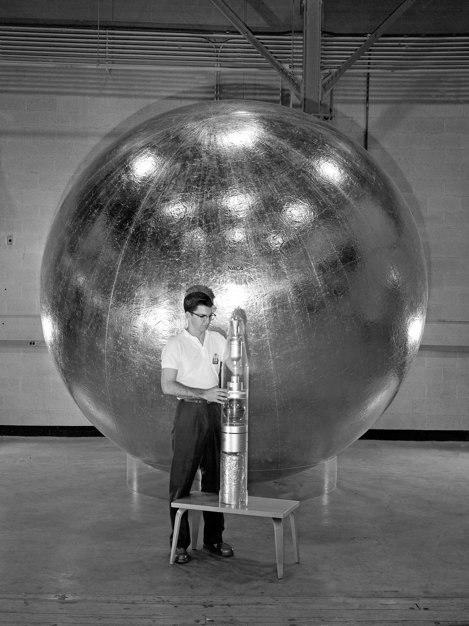
Engineer and 12 foot Beacon showing NACA emblem on inflated satelloon . For related information see, Spaceflight Revolution, NASA from Sputnik to Apollo, by James R. Hansen. NASA SP-4308, 1995. p. 173.
Wood Mock-up of Arrow- Wing Bomber to Show Wing Contours
The modified Jupiter C (sometimes called Juno I), used to launch Explorer I, had minimum payload lifting capabilities. Explorer I weighed slightly less than 31 pounds. Juno II was part of America's effort to increase payload lifting capabilities. Among other achievements, the vehicle successfully launched a Pioneer IV satellite on March 3, 1959, and an Explorer VII satellite on October 13, 1959. Responsibility for Juno II passed from the Army to the Marshall Space Flight Center when the Center was activated on July 1, 1960. On November 3, 1960, a Juno II sent Explorer VIII into a 1,000-mile deep orbit within the ionosphere.
Bell X-1B fitted with a reaction control system on the lakebed.
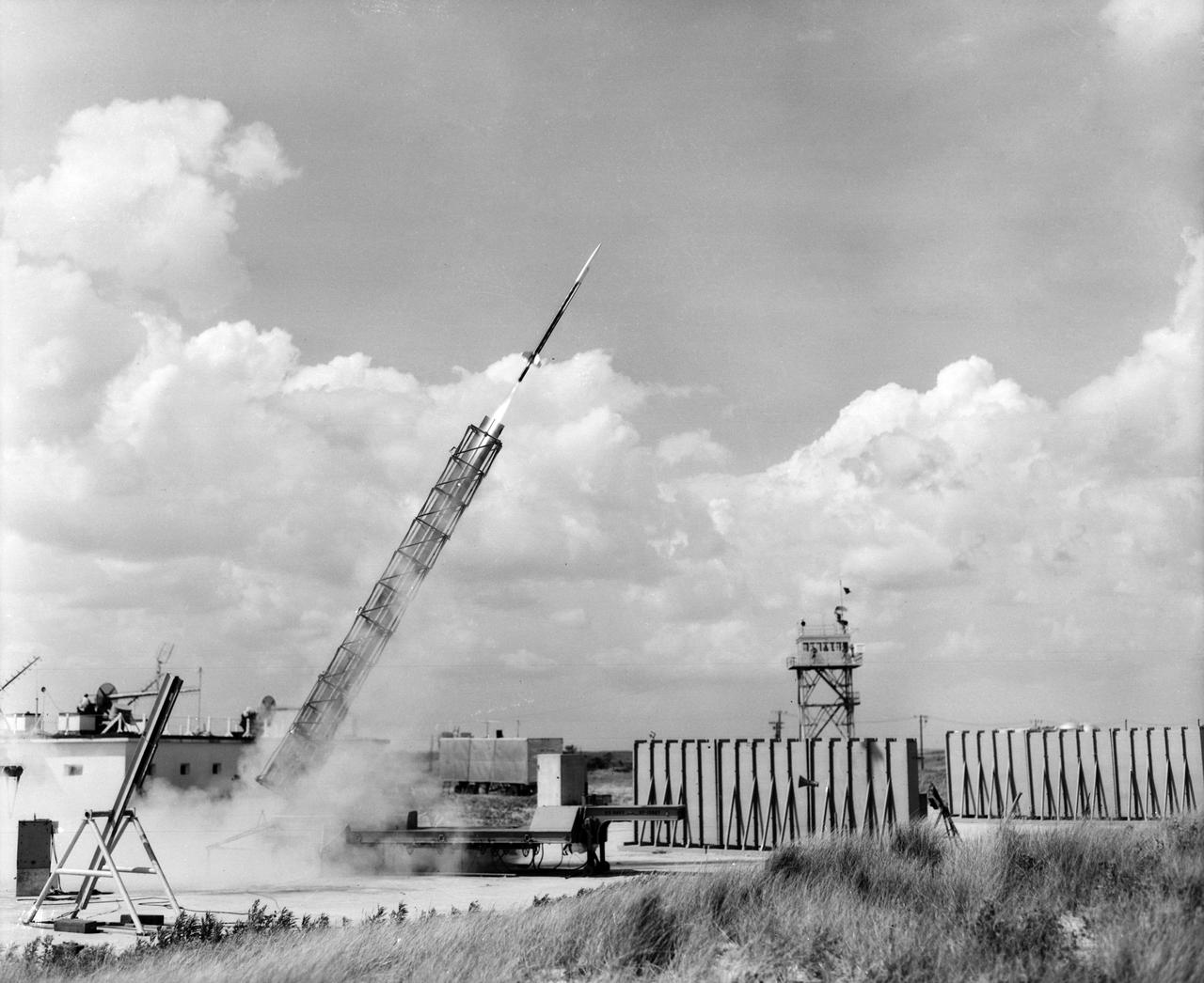
Detail and Launcher Pictures of E128-2955 (Ascon Rocket)

Photographed on: 12 09 58. -- Mercury capsule details, capsule in cargo bay of C-130 airplane prior to drop test, equipment in C130 for doing drop test.
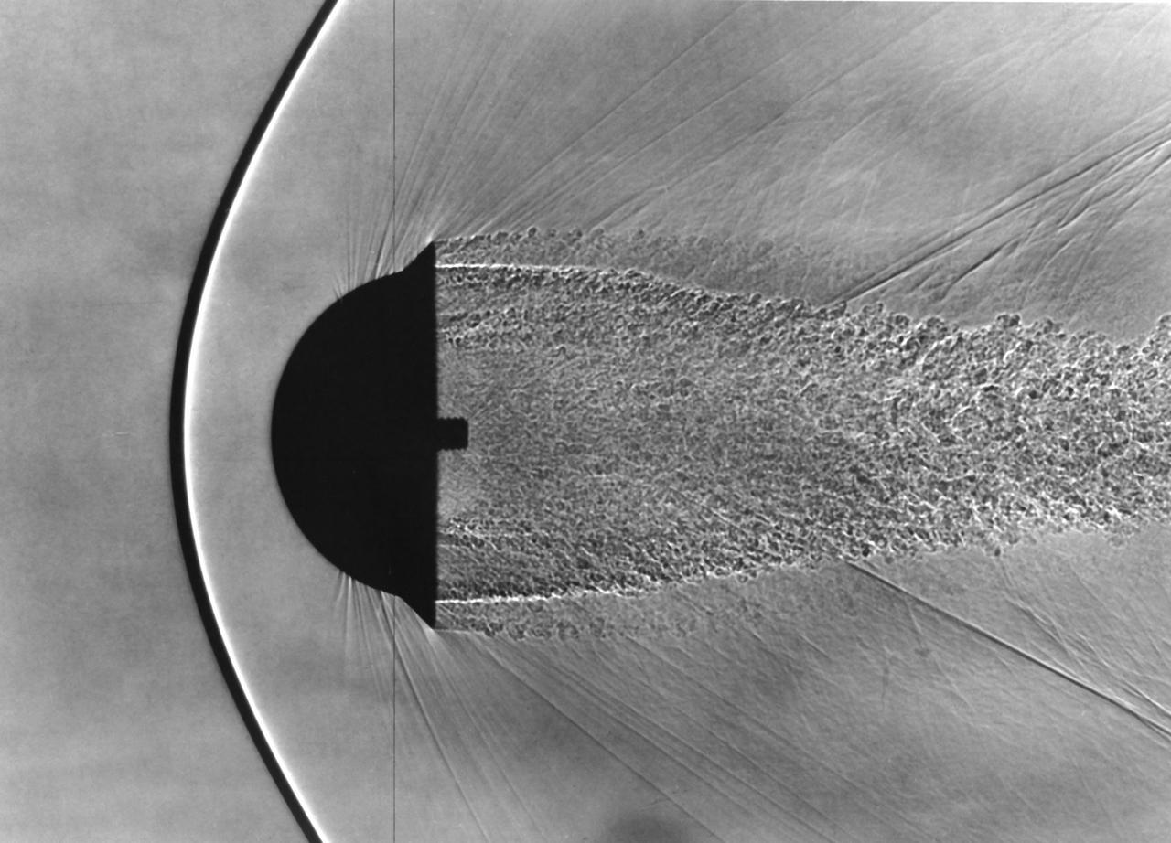
Shadowgraph of Finned Hemispherical model in free-flight show shock waves produced by blunt bodies (H. Julian Allen blunt nose theory) (Used in NASA/AMES publication 'Adventures in Research' A history of Ames Research Center 1940 - 1965 by Edwin P. Hartman - SP-4302)
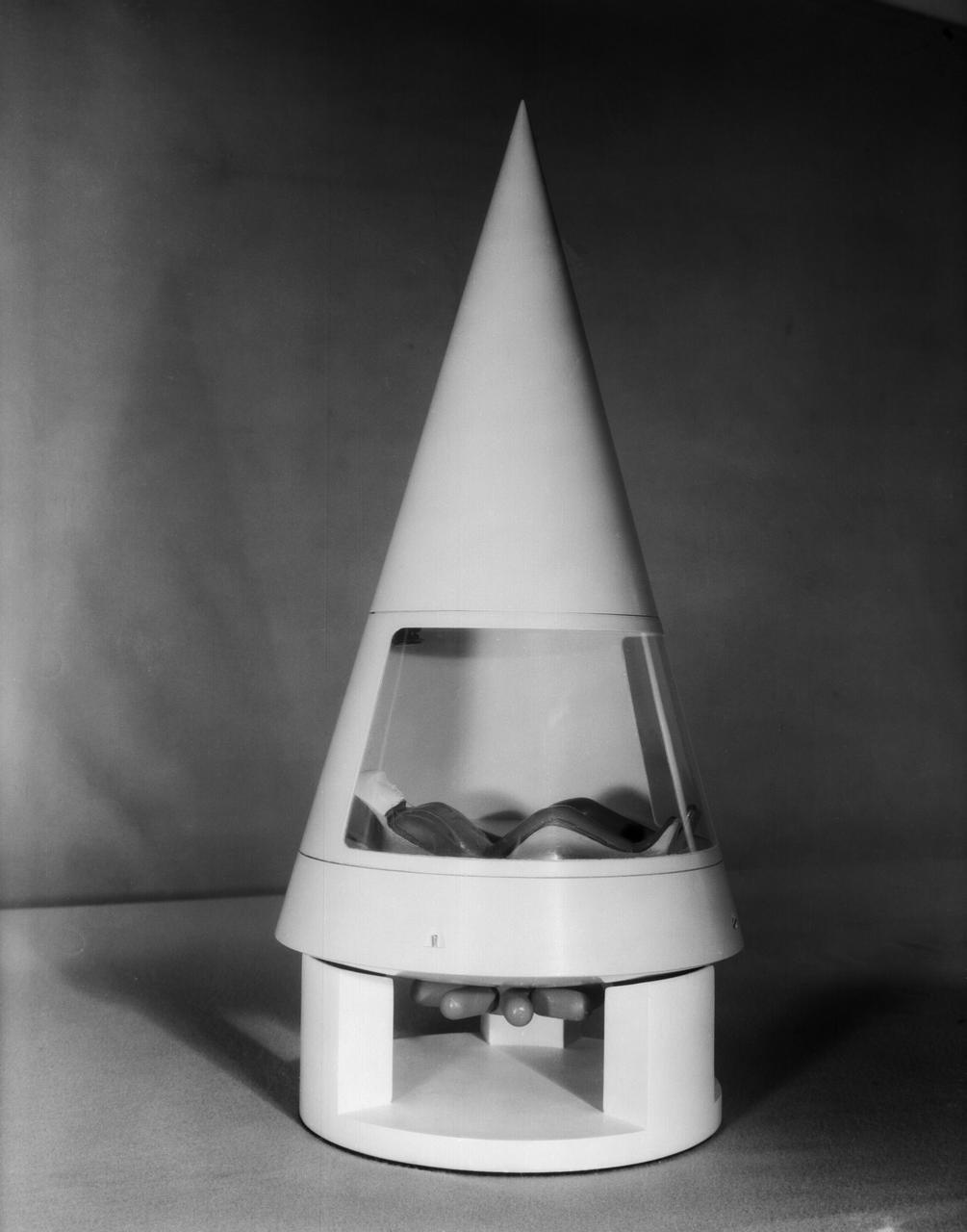
Scale model of Mercury capsule shape A, indicating the position of the astronaut.
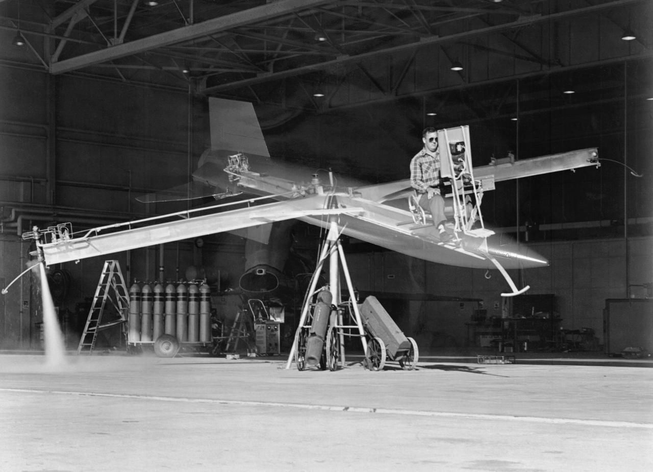
Attitude control simulator for X-15 studies at Langley, 1958. Photograph published in Engineer in Charge: A History of the Langley Aeronautical Laboratory, 1917-1958 by James R. Hansen (page 367).
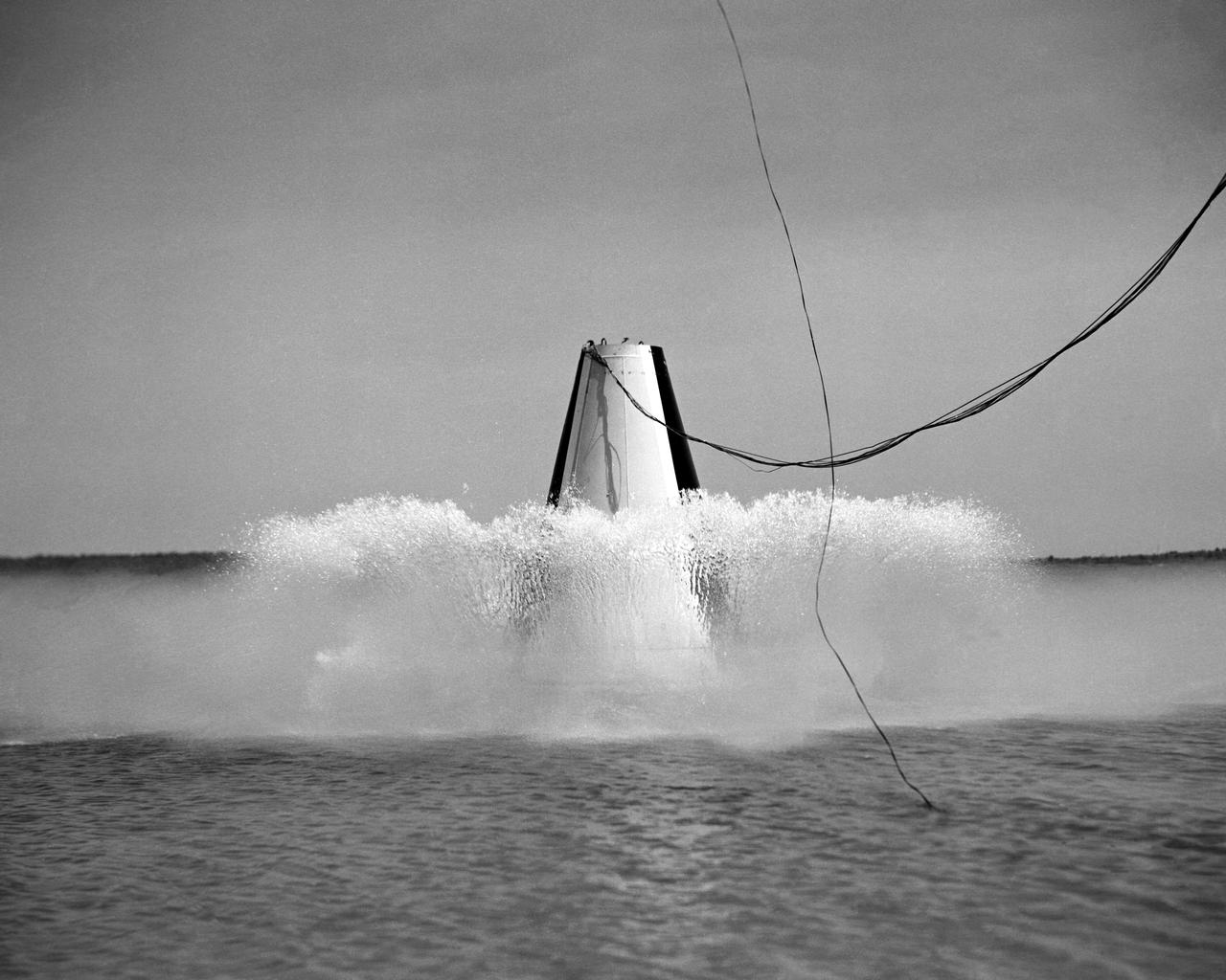
Photographed on: 08 05 1958. -- Impact test conducted by Langley's Hydrodynamics Division. The Division conducted a series of impact studies with full scale and model capsules of the original capsule shape A. Joseph Shortal wrote (Vol. 3, p. 16): The basic design of the capsule was made by M.A. Faget and his coworkers at PARD during the winter of 1957-1958. It was natural, then, that extensive use was made of the facilities at Wallops during the development of the spacecraft. The tests at Wallops consisted of 26 full-size capsules, either launched from the ground by rocket power or dropped from airplanes at high altitude and 28 scaled models, either rocket boosted or released from balloons. Emphasis in the Wallops program was on dynamic stability and aerodynamic heating of the capsule, and effectiveness of the pilot-escape and parachute-recovery systems. The biggest part of the Wallops program was the series of full-size capsules, rocket launched with the Little Joe booster, developed especially for Mercury. -- Published in Joseph A. Shortal, History of Wallops Station: Origins and Activities Through 1949, (Wallops Island, VA: National Aeronautics and Space Administration, Wallops Station, nd), Comment Edition.
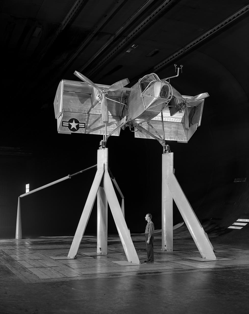
Research engineer, Harry Henninger of the Ryan Aeronautical Company, with the deflected slipstream model VZ-3RY Vertiplane.
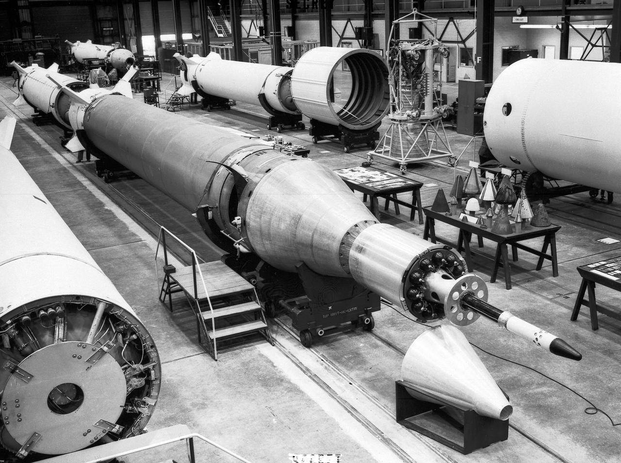
Jupiter-C Missile No. 27 assembly at the Army Ballistic Missile Agency (ABMA), Redstone Arsenal, in Huntsville, Aalabama. The Jupiter-C was a modification of the Redstone Missile, and originally developed as a nose cone re-entry test vehicle for the Jupiter Intermediate Range Ballistic Missile (IRBM). Jupiter-C successfully launched the first American Satellite, Explorer 1, in orbit on January 31, 1958.
Pilot Joe Algranti climbs into the cockpit of a McDonnell F2H-2B Banshee on the tarmac at the National Advisory Committee for Aeronautics (NACA) Lewis Flight Propulsion Laboratory. Nine months later the laboratory became part of the new National Aeronautics and Space Administration, and the NACA logo was permanently removed from the hangar. Algranti served as a Navy fighter pilot from 1946 to 1947 and earned a Physics degree from the University of North Carolina. He joined the NACA Lewis staff in 1951 witnessed the technological transformation from high speed flight to space. At Lewis Algranti piloted icing research flights, operated the liquid-hydrogen pump system for Project Bee, and served as the primary test subject for the Multi-Axis Space Test Inertia Facility (MASTIF). The MASTIF was a device used to train the Mercury astronauts how to control a spinning capsule. In 1960, Algranti and fellow Lewis pilots Warren North and Harold Ream transferred to NASA’s Space Task Group at Langley to actively participate in the space program. Two years later, Algranti became the Chief of Aircraft Operations and Chief Test Pilot at NASA’s new Manned Space Center in Houston. Algranti earned notoriety in 1968 when he test flew the first Lunar Landing Training Vehicle. He operated the vehicle four minutes before being forced to eject moments before it impacted the ground. Algranti also flew the NASA’s modified Boeing 747 Shuttle Carrier Aircraft, the Super Guppy, and the KC-135 "Vomit Comet" training aircraft. He retired in 1992 with over 40 years of NASA service.
KENNEDY SPACE CENTER, FLA. -- Explorer I, the first American satellite, is scheduled to be launched from Cape Canaveral on Jan. 29, 1958
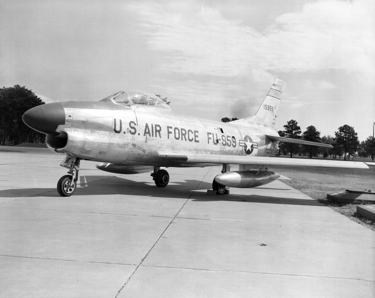
F86 D 959
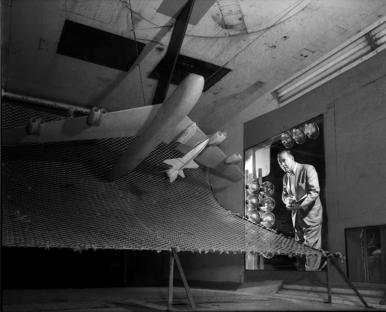
A one-twentieth scale model of the X-15 originally suspended beneath the wing of a B-52 is observed by a scientist of the National Aeronautics and Space Administration (NASA) as it leaves the bomber model in tests to determine the release characteristics and drop motion of the research airplane. Caption: The aerodynamics of air launching the North American X-15 being investigated in the 300MPH Low Speed 7x10 Tunnel, about 1957. Photograph published in Engineer in Charge: A History of the Langley Aeronautical Laboratory, 1917-1958 by James R. Hansen. Page 366. Photograph also published in Sixty Years of Aeronautical Research 1917-1977 By David A. Anderton. A NASA publication. Page 49.
North American F-100 C airplane used in sonic boom investigation at Wallops, October 7, 1958. Photograph published in: A New Dimension Wallops Island Flight Test Range: The First Fifteen Years by Joseph Shortal. A NASA publication. Page 672. -- Aircraft number: NACA 42024. Side view, 3/4 view from front, 3/4 view from rear, rear view, and two front views.
WS-110A Brown Bomber in Unitary Wind Tunnel Low Mach Number Test
Research Model in the 7x10 High Speed Tunnel Building 1212B 300 mph tunnel
Testing of Mercury Capsule Shape A by the Hydrodynamics Division of Langley. Joseph Shortal wrote (vol. 3, p. 19): The Hydrodynamics Division provided assistance in determining landing loads. In this connection, after PARD engineers had unofficially approached that division to make some water impact tests with the boilerplate capsule, J.B. Parkinson, Hydrodynamics Chief visited Shortal to find out if the request had his support. Finding out that it did, Parkinson said, Its your capsule. If you want us to drop it in the water, we will do it. From Shortal (Vol. 3, p. 16): The basic design of the capsule was made by M.A. Faget and his coworkers at PARD during the winter of 1957-1958. It was natural, then, that extensive use was made of the facilities at Wallops during the development of the spacecraft. The tests at Wallops consisted of 26 full-size capsules, either launched from the ground by rocket power or dropped from airplanes at high altitude and 28 scaled models, either rocket boosted or released from balloons. Emphasis in the Wallops program was on dynamic stability and aerodynamic heating of the capsule, and effectiveness of the pilot-escape and parachute-recovery systems. The biggest part of the Wallops program was the series of full-size capsules, rocket launched with the Little Joe booster, developed especially for Mercury. -- Published in Joseph A. Shortal, History of Wallops Station: Origins and Activities Through 1949, (Wallops Island, VA: National Aeronautics and Space Administration, Wallops Station, nd), Comment Edition.
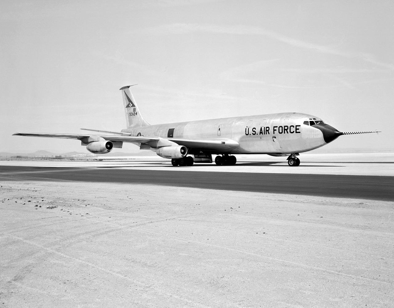
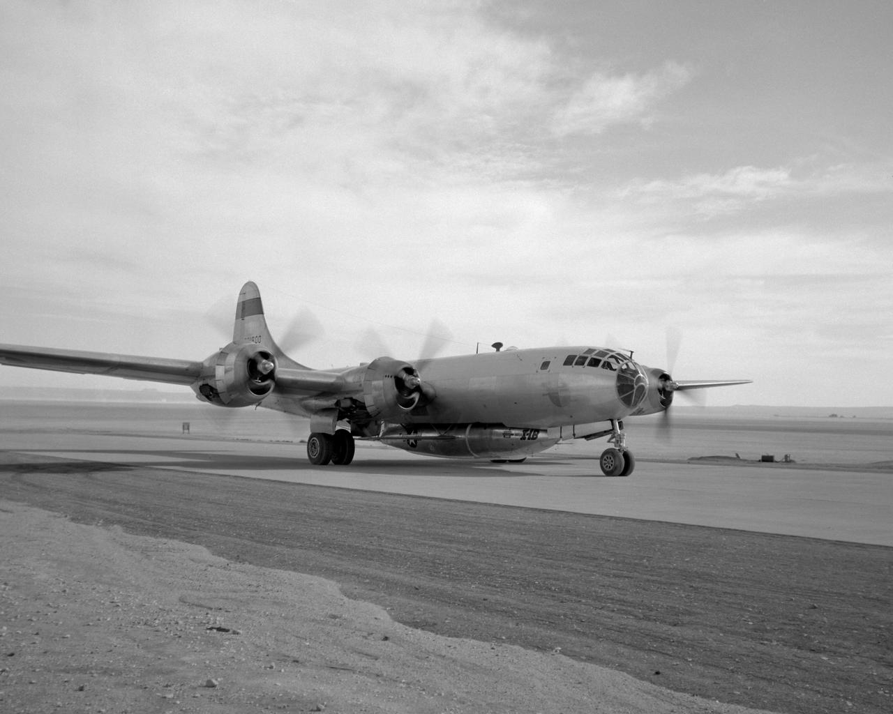
The Boeing KC-135 Stratotanker, besides being used extensively in its primary role as an inflight aircraft refueler, has assisted in several projects at the NASA Dryden Flight Research Center, Edwards, California. In 1957 and 1958, Dryden was asked by what was then the Civil Aeronautics Administration (later absorbed into the Federal Aviation Administration (FAA) in 1958) to help establish new approach procedure guidelines on cloud-ceiling and visibility minimums for Boeing's first jet airliner, the B-707. Dryden used a KC-135 (the military variant of the 707), seen here on the runway at Edwards Air Force Base, to aid the CAA in these tests. In 1979 and 1980, Dryden was again involved with general aviation research with the KC-135. This time, a special wingtip "winglet", developed by Richard Whitcomb of Langley Research Center, was tested on the jet aircraft. Winglets are small, nearly vertical fins installed on an airplane's wing tips to help produce a forward thrust in the vortices that typically swirl off the end of the wing, thereby reducing drag. This winglet idea was tested at the Dryden Flight Research Center on a KC-135A tanker loaned to NASA by the Air Force. The research showed that the winglets could increase an aircraft's range by as much as 7 percent at cruise speeds. The first application of NASA's winglet technology in industry was in general aviation business jets, but winglets are now being incorporated into most new commercial and military transport jets, including the Gulfstream III and IV business jets, the Boeing 747-400 and MD-11 airliners, and the C-17 military transport. In the 1980's, a KC-135 was used in support of the Space Shuttle program. Since the Shuttle was to be launched from Florida, researchers wanted to test the effect of rain on the sensitive thermal tiles. Tiles were mounted on special fixtures on an F-104 aircraft and a P-3 Orion. The F-104 was flown in actual rain conditions, and also behind the KC-135 spray tanker as it rel
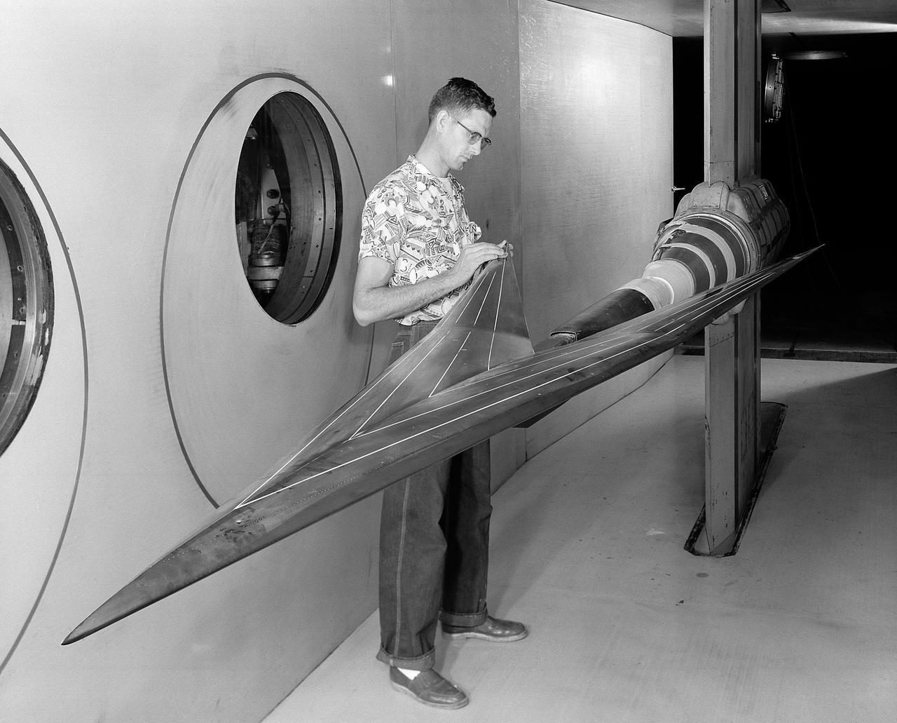
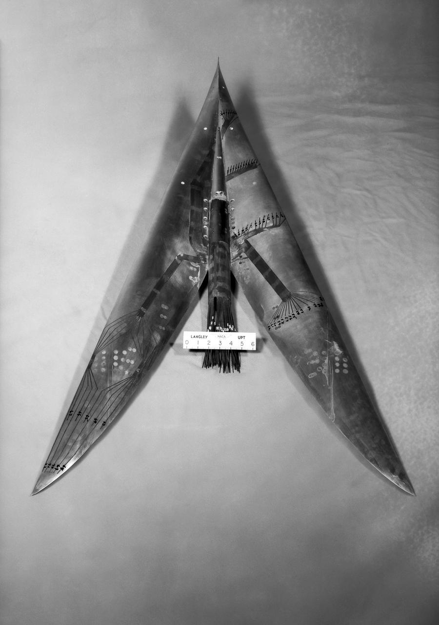
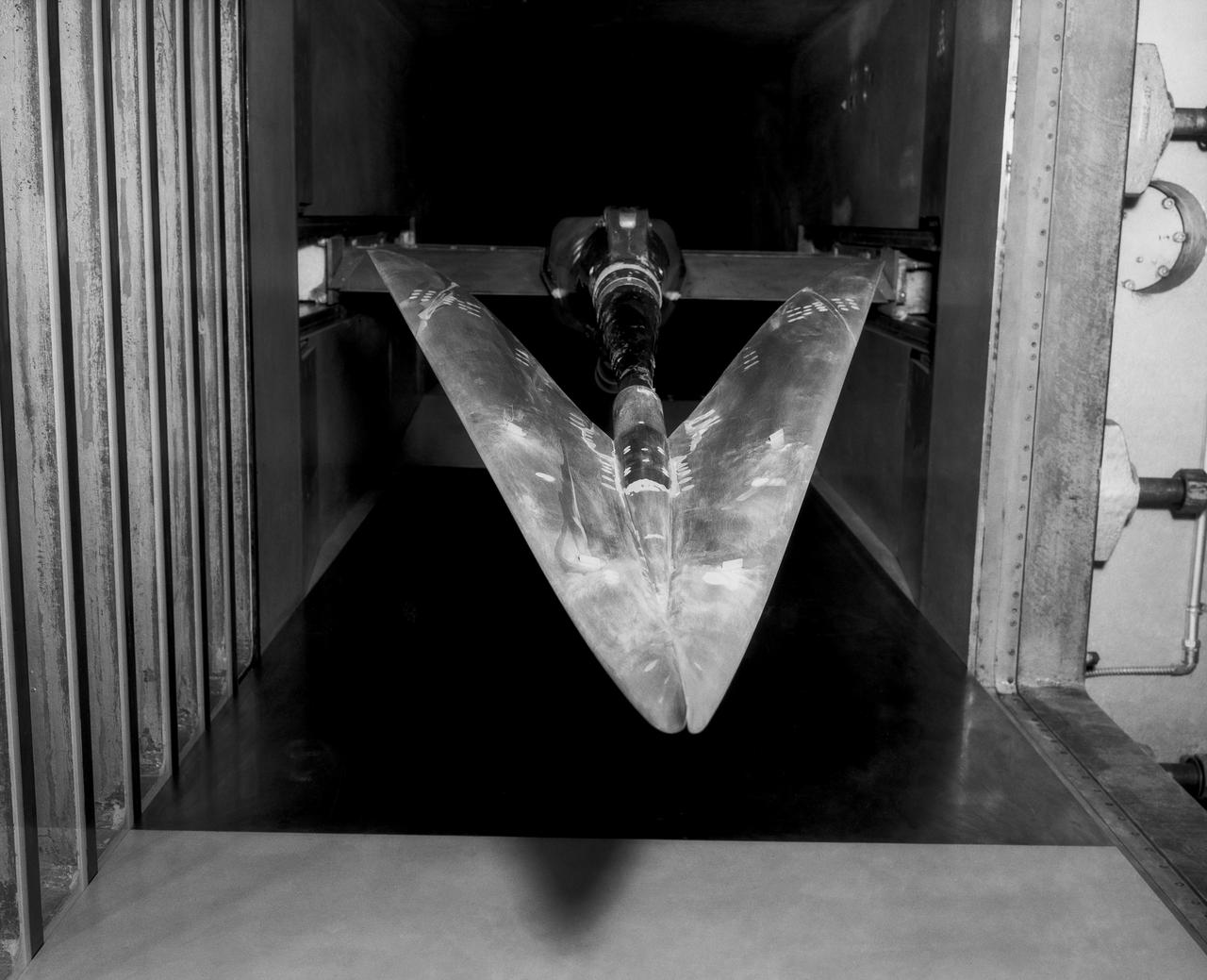
A chambered and twisted wing-body. Arrow wing hypersonic model tested in the 6x6 foot wind tunnel at the NASA Ames Research Center.
Operation Airlift
Dr A J Eggers, Jr. at small scale Entry Simulator
Brown Arrow Wing Bomber

Russell G Robinson, Assistant Director Ames Research Center
KENNEDY SPACE CENTER, FLA. -- Waiting for the Vanguard 1 launch.
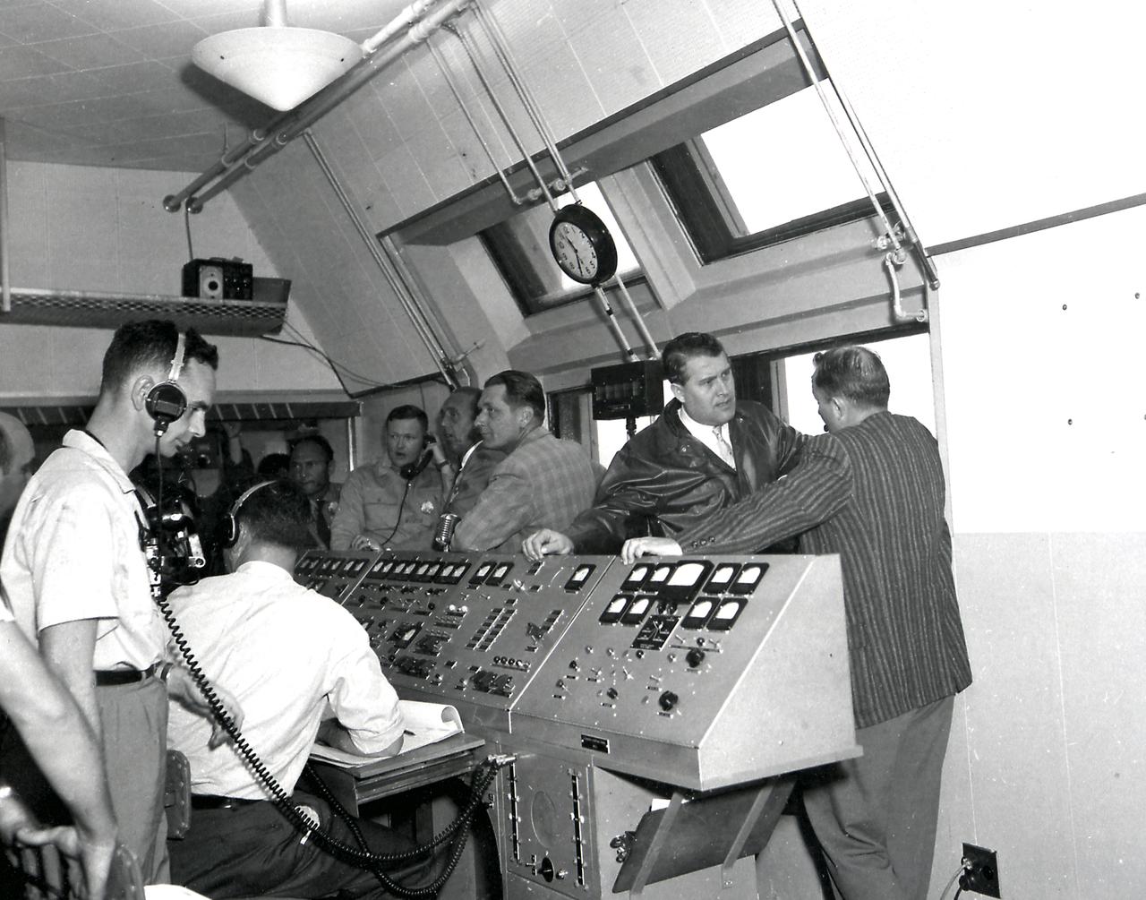
Dr. von Braun inside the blockhouse during the launch of the Jupiter C/Explorer III in March 1958.
Prop Damage in the 8 foot TT (Transfer Tunnel)
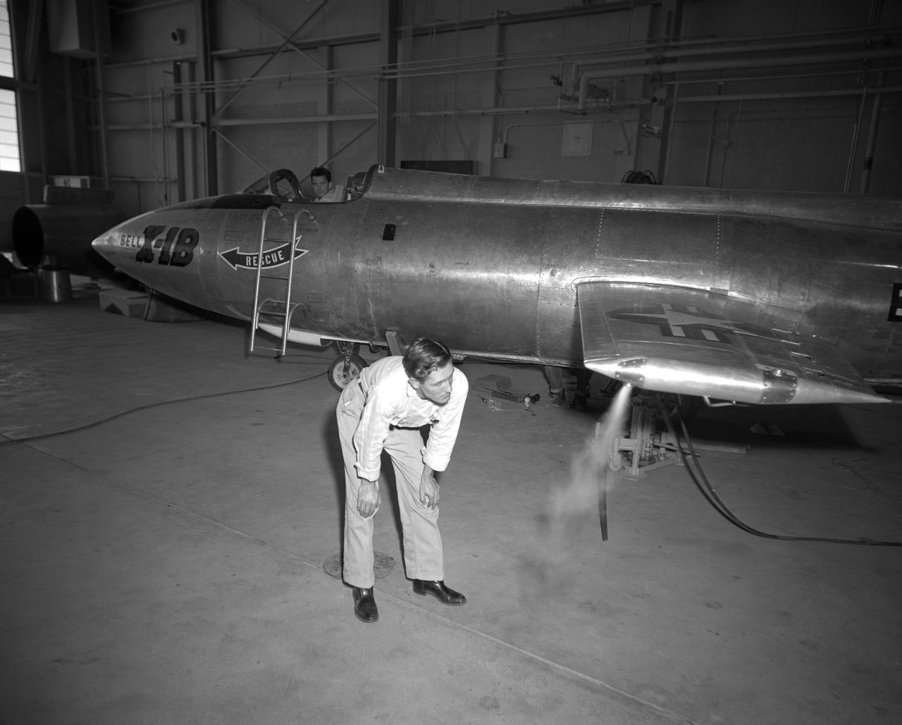
The X-1B reaction control system thrusters are tested in 1958 and later proven on the X-15 as a way to control a vehicle in the absence of dynamic pressure.
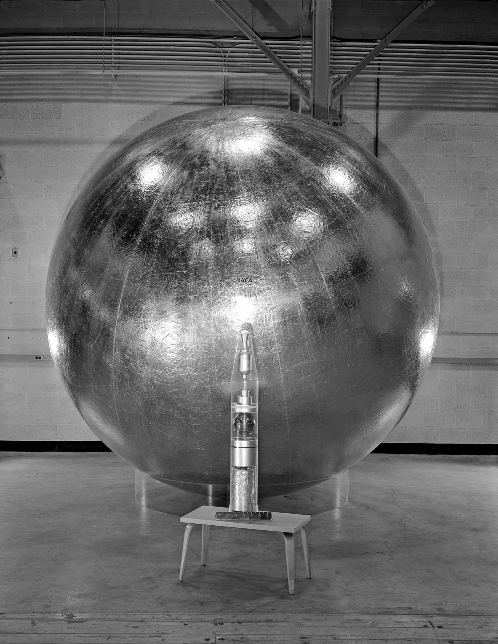
Engineer and 12 foot Beacon showing NACA emblem on inflated satelloon . For related information see, Spaceflight Revolution, NASA from Sputnik to Apollo, by James R. Hansen. NASA SP-4308, 1995. p. 173.
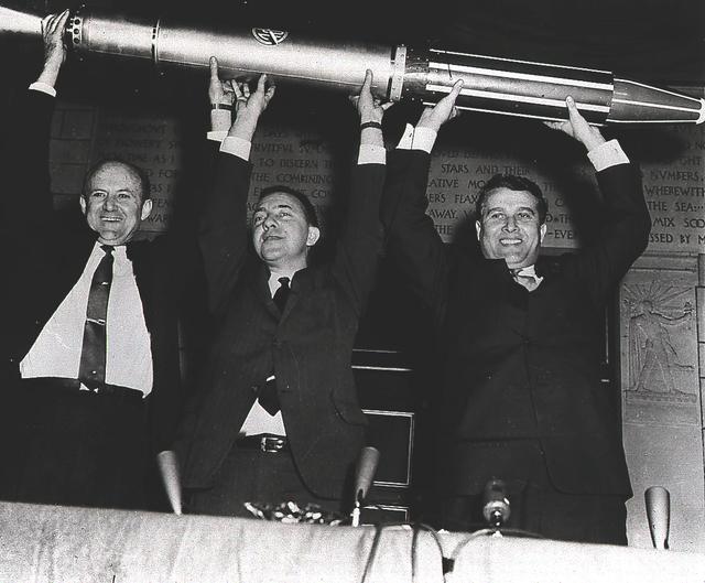
Jet Propulsion Laboratory Director Dr. William Pickering, Dr. James van Allen of the State University of Iowa, and Army Ballistic missionile Agency Technical Director Dr. Wernher von Braun triumphantly display a model of the Explorer I, America's first satellite, shortly after the satellite's launch on January 31, 1958. The Jet Propulsion Laboratory packed and tested the payload, a radiation detection experiment designed by Dr. van Allen. Dr. von Braun's rocket team at Redstone Arsenal in Huntsville, Alabama, developed the Juno I launch vehicle, a modified Jupiter-C.
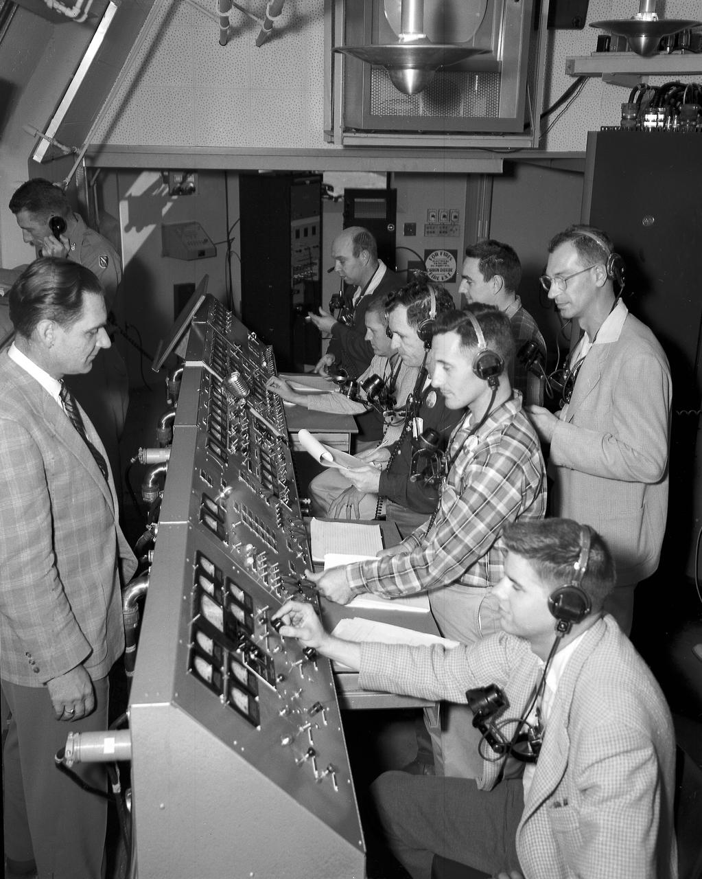
Activities in a blockhouse during the launch of Jupiter-C/Explorer 1 on January 31, 1958
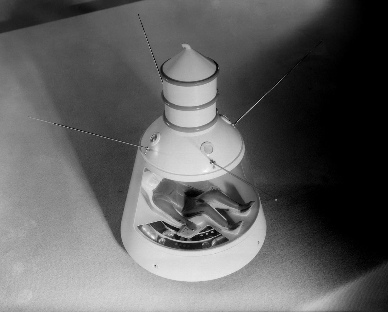
Scale model of Mercury capsule shape A, indicating the position of the astronaut.