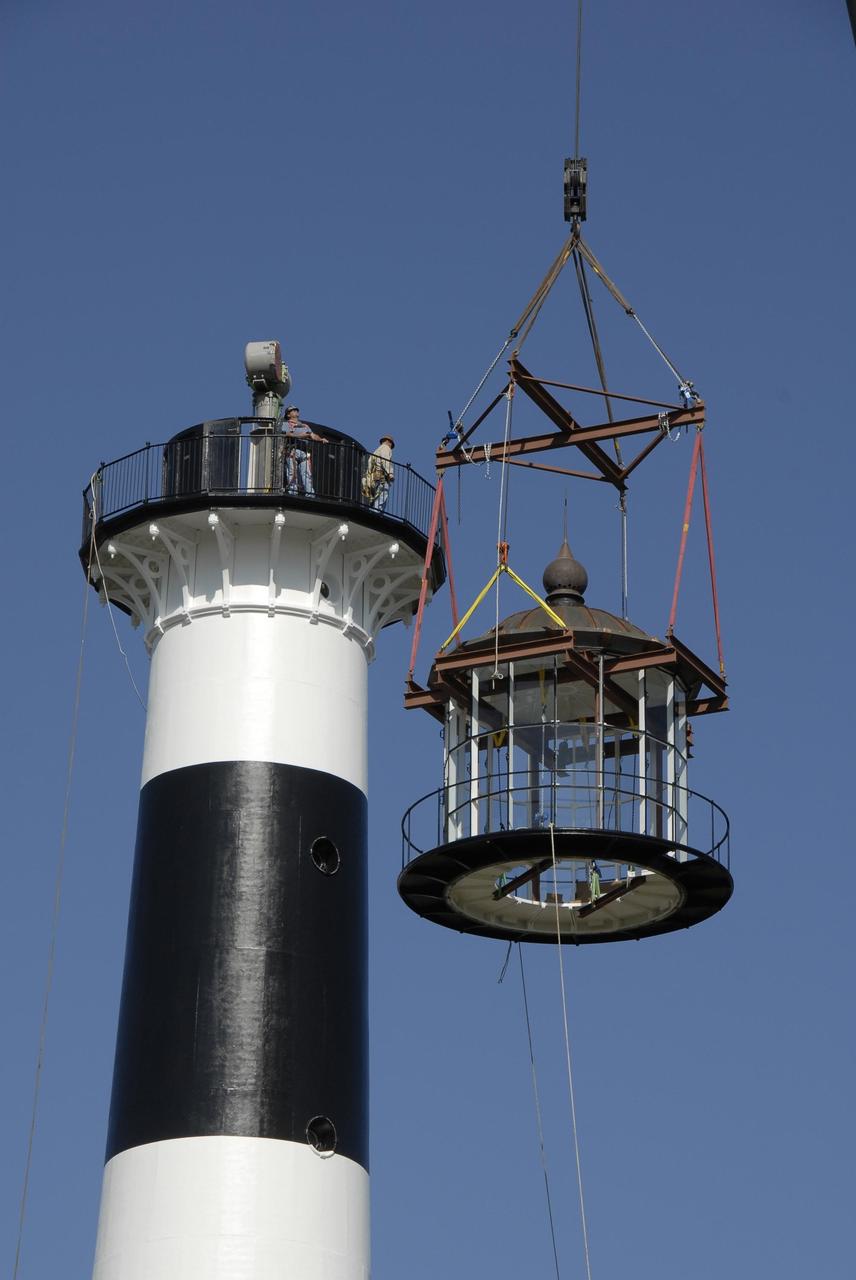
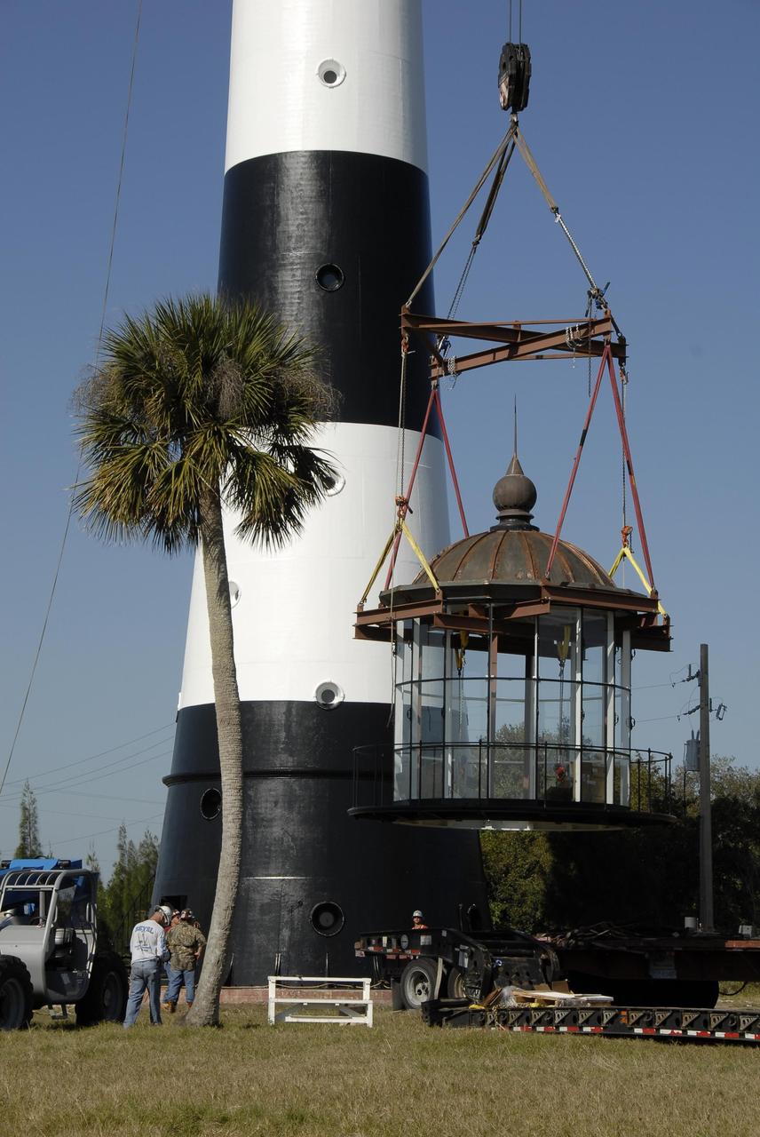
SHELL BUCKLE KNOCKDOWN FACTOR (SBKF) COMPOSITE BARREL EPOXY POUR
POURING EPOXY
Jessica Sunshine, EPOXI Deputy Principal Investigator, University of Maryland, far right, discusses imagery sent back from the EPOXI Mission spacecraft during a press conference, Thursday, Nov. 18, 2010, at NASA Headquarters in Washington. The press conference was held to discuss the Nov. 4 successful flyby of Comet Hartley 2 by NASA's EPOXI Mission Spacecraft. Images from the flyby provided scientists the most extensive observations of a comet in history. Photo Credit: (NASA/Paul E. Alers)
EPOXI Mission Press Conference
SHELL BUCKLE KNOCKDOWN FACTOR (SBKF) COMPOSITE BARREL EPOXY POUR.
TECHNICIANS MIX EPOXY
SHELL BUCKLE KNOCKDOWN FACTOR (SBKF) COMPOSITE BARREL EPOXY POUR.
TECHNICIANS MIX EPOXY
SHELL BUCKLE KNOCKDOWN FACTOR (SBKF) COMPOSITE BARREL EPOXY POUR
CHECKING DEPTH OF EPOXY
SHELL BUCKLE KNOCKDOWN FACTOR (SBKF) COMPOSITE BARREL EPOXY POUR.
TECHNICIANS MIX EPOXY
SHELL BUCKLE KNOCKDOWN FACTOR (SBKF) COMPOSITE BARREL EPOXY POUR
FILLED EPOXY SEAM
SHELL BUCKLE KNOCKDOWN FACTOR (SBKF) COMPOSITE BARREL EPOXY POUR
MEASURING FLOW RATE OF EPOXY MIXTURE
SHELL BUCKLE KNOCKDOWN FACTOR (SBKF) COMPOSITE BARREL EPOXY POUR
MEASURING FLOW RATE OF EPOXY MIXTURE
Michael A'Hearn, EPOXI Principal Investigator, University of Maryland, holds a plastic bottle containing ice to illustrate a point during a press conference, Thursday, Nov. 18, 2010, at NASA Headquarters in Washington. The press conference was held to discuss the Nov. 4 successful flyby of Comet Hartley 2 by NASA's EPOXI Mission Spacecraft. Images from the flyby provided scientists the most extensive observations of a comet in history. Photo Credit: (NASA/Paul E. Alers)
EPOXI Mission Press Conference
Pete Schultz, EPOXI scientist from Brown University, makes a point during a press conference, Thursday, Nov. 18, 2010, at NASA Headquarters in Washington. The press conference was held to discuss the Nov. 4 successful flyby of Comet Hartley 2 by NASA's EPOXI Mission Spacecraft. Images from the flyby provided scientists the most extensive observations of a comet in history. Photo Credit: (NASA/Paul E. Alers)
EPOXI Mission Press Conference
Tim Larson, EPOXI Project Manager from the Jet Propulsion Laboratory in Pasadena, Calif., speaks during a press conference, Thursday, Nov. 18, 2010, at NASA Headquarters in Washington. The press conference was held to discuss the Nov. 4 successful flyby of Comet Hartley 2 by NASA's EPOXI Mission Spacecraft. Images from the flyby provided scientists the most extensive observations of a comet in history. Photo Credit: (NASA/Paul E. Alers)
EPOXI Mission Press Conference
Michael A'Hearn, EPOXI Principal Investigator, University of Maryland, holds a plastic bottle containing ice to illustrate a point during a press conference, Thursday, Nov. 18, 2010, at NASA Headquarters in Washington. The press conference was held to discuss the Nov. 4 successful flyby of Comet Hartley 2 by NASA's EPOXI Mission Spacecraft. Images from the flyby provided scientists the most extensive observations of a comet in history. Photo Credit: (NASA/Paul E. Alers)
EPOXI Mission Press Conference
Jessica Sunshine, EPOXI Deputy Principal Investigator, University of Maryland, far right, discusses imagery sent back from the EPOXI Mission spacecraft during a press conference, Thursday, Nov. 18, 2010, at NASA Headquarters in Washington. The press conference was held to discuss the Nov. 4 successful flyby of Comet Hartley 2 by NASA's EPOXI Mission Spacecraft. Images from the flyby provided scientists the most extensive observations of a comet in history. Photo Credit: (NASA/Paul E. Alers)
EPOXI Mission Press Conference
SHELL BUCKLE KNOCKDOWN FACTOR (SBKF) COMPOSITE BARREL EPOXY POUR.
TECHNICIANS AND ENGINEERS DISCUSS EPOXY POURING PROCESS
This zoomed-in image from the High-Resolution Instrument on NASA EPOXI mission spacecraft shows the particles swirling in a now storm around the nucleus of comet Hartley 2.
Cometary Flurries
This close-up view of comet Hartley 2 was taken at 7:00 a.m. PDT 10 a.m. EDT, after NASA EPOXI mission flew by.
Leaving Comet Hartley 2
This close-up view of comet Hartley 2 was taken as NASA EPOXI mission approached the comet at 6:59 a.m. PDT 9:59 a.m. EDT.
Almost There at Comet Hartley 2
This close-up view of comet Hartley 2 was taken as NASA EPOXI mission approached the comet at 6:58 a.m. PDT 9:58 a.m. EDT.
Closing in on Comet Hartley 2
This close-up view of comet Hartley 2 was taken at 7:00 a.m. PDT 10 a.m. EDT, after NASA EPOXI mission flew by.
Slipping By Comet Hartley 2
This image montage shows comet Hartley 2 as NASA EPOXI mission approached and flew under the comet. The images progress in time clockwise, starting at the top left.
Flying Under Comet Hartley 2
This image shows the nuclei of comets Tempel 1 and Hartley 2, as imaged by NASA Deep Impact spacecraft, which continued as an extended mission known as EPOXI.
Tempel 1 and Hartley 2
Dr. James Green, Director of Planetary Science, NASA Headquarters, at podium, speaks during a press conference, Thursday, Nov. 18, 2010, at NASA Headquarters in Washington. The press conference was held to discuss the Nov. 4 successful flyby of Comet Hartley 2 by NASA's EPOXI Mission Spacecraft. Images from the flyby provided scientists the most extensive observations of a comet in history. Photo Credit: (NASA/Paul E. Alers)
EPOXI Mission Press Conference
This enhanced image, one of the closest taken of comet Harley 2 by NASA EPOXI mission, shows jets and where they originate from the surface. There are jets outgassing from the sunward side, the night side, and along the terminator.
Jets Galore
This image, one of the closest taken of comet Hartley 2 by NASA EPOXI mission, shows many features across the comet surface. The length of the comet is equal to the distance between the Capitol building and the Washington Monument in Washington.
Up Close and Personal with Hartley 2
This image from NASA EPOXI mission shows Hartley 2 moving across the background field of stars. The coma, or cloud of gas and dust around the comet, expands and brightens over this time period. Animation available at the Photojournal.
Hartley 2 on the Move
NASA EPOXI mission spacecraft obtained these views of the icy particle cloud around comet Hartley 2. The image on the left is the full image of comet Hartley 2 for context, and the image on the right was enlarged and cropped.
Views of Hartley 2 Nucleus and Inner Coma
Image taken by NASA EPOXI mission spacecraft during its flyby of comet Hartley 2 on Nov. 4, 2010. The spacecraft came within about 700 kilometers 435 miles of the comet nucleus at the time of closest approach.
Flight of the Comet
This image from the High-Resolution Instrument on NASA EPOXI mission spacecraft shows part of the nucleus of comet Hartley 2. The sun is illuminating the nucleus from the right. A distinct cloud of individual particles is visible.
Hartley 2, Close Up
NASA EPOXI mission took this image of comet Hartley 2 on Nov. 2, 2010. The spacecraft will fly by the comet on Nov. 4, 2010. The white blob and the halo around it are the comet outer cloud of gas and dust, called a coma.
Comet Hartley 2 Looms Large in the Sky
Infrared scans of comet Hartley 2 by NASA EPOXI mission spacecraft show carbon dioxide, dust, and ice being distributed in a similar way and emanating from apparently the same locations on the nucleus.
The Many Faces of Hartley 2
Icy particles in the cloud around Hartley 2, as seen by NASA EPOXI mission spacecraft. A star moving through the background is marked with red and moves in a particular direction, with a particular speed; icy particles move in random directions.
Tracking Snowballs
This montage from NASA EPOXI mission shows the only five comets imaged up close with spacecraft. The comets vary in shape and size. Comet Hartley 2 is by far the smallest and the most active of small comets.
Fab Five
These three pairs of images from NASA EPOXI mission demonstrate that a dust jet and gaseous carbon dioxide are being released from comet Hartley 2 at the same time, and from the same location on the comet.
Evidence for a First-of-Its-Kind Comet Jet
PHILLIP THOMPSON APPLIES EPOXY RESIN TO BURST TEST ARTICLE
1300593
Images obtained by NASA EPOXI mission spacecraft show an active end of the nucleus of comet Hartley 2. Icy particles spew from the surface. Most of these particles are traveling with the nucleus; fluffy nowballs about 3 centimeters to 30 centimeters.
Icy Particle Spray
The upper panel of this figure shows small images of comet Hartley 2 taken by NASA EPOXI mission over time. The lower panel is a graph showing the variation of total brightness, and the variation of the total amount of carbon dioxide, during the time.
Carbon Dioxide Fluctuations in Comet Hartley 2
Comet Hartley 2 can be seen in glorious detail in this image from NASA EPOXI mission. It was taken as the spacecraft flew by around 6:59 a.m. PDT 9:59 a.m. EDT, from a distance of about 700 kilometers 435 miles.
Introducing Comet Hartley 2
This artist concept shows a view of NASA EPOXI mission spacecraft during its Nov. 4, 2010 flyby of comet Hartley 2. The fluffy shell around the comet, called a coma, is made up of gas and dust that blew off the comet core, or nucleus.
Comet Hartley 2 Gets a Visitor Artist Concept
This frame from a movie begins with the launch of NASA Deep Impact on Jan. 12, 2005, from Cape Canaveral, Fla. On July 4, 2005, the mission released a probe into Comet Tempel 1, revealing its pristine, inner material.
EPOXI Trip to Meet Comet Hartley 2
Dr. Michael A'Hearn, Principal Investigator, EPOXI Comet Encounter Mission, speaks during a symposium commemorating a quarter-century of comet discoveries, Friday, Sept. 10, 2010, in the Knight studio at the Newseum in Washington. The International Sun-Earth Explorer-3 (ISEE-3) spacecraft flew past the comet Giacobini-Zinner on Sept. 11, 1985 which established a foundation of discoveries that continue today. Photo Credit: (NASA/Paul E. Alers)
First Comet Encounter
This visitor from deep space, seen here by NASA Wide-field Infrared Survey Explorer, is comet Hartley 2, the destination for NASA EPOXI mission. The comet tail is seen here as a fuzzy streak to the right of the comet.
Icy Visitor from Beyond
Workers at NASA Deep Space Network complex in Goldstone, Calif., pour in a new epoxy grout as the giant Mars
Pouring the New Grout
As the sun sets on July 8, 2010, workers prepare to pour new epoxy grout for the hydrostatic bearing assembly of the giant Mars
Mars Antenna Ready for Surgery
This 3-D image shows the region where NASA Deep Impact mission sent a probe into the surface of comet Tempel 1 in 2005. This picture was taken six years after the Deep Impact collision. 3D glasses are necessary to view this image.
Hartley 2 in 3-D
NASA Deep Impact spacecraft High- and Medium-Resolution Imagers HRI and MRI captured multiple jets emanating from comet Hartley 2 turning on and off while the spacecraft is 8 million kilometers 5 million miles away from the comet.
Spacecraft Images Comet Target Jets
An epoxy is applied to adhere the fiber optic sensor installation on the Mock Truss-Braced Wing 10-foot model at NASA’s Armstrong Flight Research Center in Edwards, California.
NASA Prepares for Mock Truss-Braced Wing Tests
Using NASA Herschel Space Observatory, astronomers have discovered that comet Hartley 2 possesses a ratio of heavy water to light, or normal, water that matches what found in Earth oceans.
Heavy and Light Just Right
New measurements from NASA Herschel Space Observatory have discovered water with the same chemical signature as our oceans in a comet called Hartley 2 pictured at right. The image at bottom right is an artist concept of a comet.
The Same Here as There
Engineering technician Jeff Howell removes tape from the Mock Truss-Braced Wing 10-foot model at NASA’s Armstrong Flight Research Center in Edwards, California. The tape was used to limit the amount of epoxy on the model wing during the process to secure the fiber optic strain sensors to the wing.
NASA Prepares for Mock Truss-Braced Wing Tests
CAPE CANAVERAL, Fla. --    In Building 1555 at Vandenberg Air Force Base in California, ssembly is underway for the Taurus XL rocket that will launch NASA's Orbiting Carbon Observatory, or OCO, spacecraft.  Lined up left to right are the Stage 1 and Stage 2 motors, the boattail, the avionics shelf and the Stage 3 motor.  The graphite/epoxy boattail structure provides the transition from the smaller diameter of the Stage 2 motor to the larger diameter of the avionics skirt. The avionics skirt, also a graphite/epoxy structure, supports the avionics shelf and carries the primary structural loads from the fairing and payload cone. The aluminum avionics shelf supports the third stage avionics. The OCO is a new Earth-orbiting mission sponsored by NASA's Earth System Science Pathfinder Program. The launch of OCO is targeted for January.  Photo credit: NASA/Randy Beaudoin, VAFB
KSC-08pd3866
Engineers at Marshall Space Flight Center (MSFC) in Huntsville, Alabama, are working with industry partners to develop a new generation of more cost-efficient space vehicles. Lightweight fuel tanks and components under development will be the critical elements in tomorrow's reusable launch vehicles and will tremendously curb the costs of getting to space. In this photo, Tom DeLay, a materials processes engineer for MSFC, uses a new graphite epoxy technology to create lightweight cryogenic fuel lines for futuristic reusable launch vehicles. He is wrapping a water-soluble mandrel, or mold, with a graphite fabric coated with an epoxy resin. Once wrapped, the pipe will be vacuum-bagged and autoclave-cured. The disposable mold will be removed to reveal a thin-walled fuel line. In addition to being much lighter and stronger than metal, this material won't expand or contract as much in the extreme temperatures encountered by launch vehicles.
Research Technology
KENNEDY SPACE CENTER, FLA. - In the Orbiter Processing Facility, one of two orbital maneuvering system (OMS) pods is being moved for installation on Atlantis.  The OMS pods are attached to the upper aft fuselage left and right sides. Fabricated primarily of graphite epoxy composite and aluminum, each pod is 21.8 feet long and 11.37 feet wide at its aft end and 8.41 feet wide at its forward end, with a surface area of approximately 435 square feet. Each pod houses the Reaction Control System propulsion components used for inflight maneuvering and is attached to the aft fuselage with 11 bolts.
KENNEDY SPACE CENTER, FLA. - In the Orbiter Processing Facility, one of two orbital maneuvering system (OMS) pods is being moved for installation on Atlantis. The OMS pods are attached to the upper aft fuselage left and right sides. Fabricated primarily of graphite epoxy composite and aluminum, each pod is 21.8 feet long and 11.37 feet wide at its aft end and 8.41 feet wide at its forward end, with a surface area of approximately 435 square feet. Each pod houses the Reaction Control System propulsion components used for inflight maneuvering and is attached to the aft fuselage with 11 bolts.
KENNEDY SPACE CENTER, FLA. - In the Orbiter Processing Facility, technicians move an orbital maneuvering system (OMS) pod into the correct position on Atlantis. The OMS pod is one of two that are attached to the upper aft fuselage left and right sides. Fabricated primarily of graphite epoxy composite and aluminum, each pod is 21.8 feet long and 11.37 feet wide at its aft end and 8.41 feet wide at its forward end, with a surface area of approximately 435 square feet. Each pod houses the Reaction Control System propulsion components used for inflight maneuvering and is attached to the aft fuselage with 11 bolts.
KENNEDY SPACE CENTER, FLA. - In the Orbiter Processing Facility, an orbital maneuvering system (OMS) pod is moved into place on Atlantis.  It is one of two OMS pods attached to the upper aft fuselage left and right sides. Fabricated primarily of graphite epoxy composite and aluminum, each pod is 21.8 feet long and 11.37 feet wide at its aft end and 8.41 feet wide at its forward end, with a surface area of approximately 435 square feet. Each pod houses the Reaction Control System propulsion components used for inflight maneuvering and is attached to the aft fuselage with 11 bolts.
KENNEDY SPACE CENTER, FLA. - In the Orbiter Processing Facility, an orbital maneuvering system (OMS) pod is moved into place on Atlantis. It is one of two OMS pods attached to the upper aft fuselage left and right sides. Fabricated primarily of graphite epoxy composite and aluminum, each pod is 21.8 feet long and 11.37 feet wide at its aft end and 8.41 feet wide at its forward end, with a surface area of approximately 435 square feet. Each pod houses the Reaction Control System propulsion components used for inflight maneuvering and is attached to the aft fuselage with 11 bolts.
KENNEDY SPACE CENTER, FLA. - In the Orbiter Processing Facility, workers discuss the next step in moving the orbital maneuvering system (OMS) pod behind them.  The OMS pod will be installed on Atlantis.  Two OMS pods are attached to the upper aft fuselage left and right sides. Fabricated primarily of graphite epoxy composite and aluminum, each pod is 21.8 feet long and 11.37 feet wide at its aft end and 8.41 feet wide at its forward end, with a surface area of approximately 435 square feet. Each pod houses the Reaction Control System propulsion components used for inflight maneuvering and is attached to the aft fuselage with 11 bolts.
KENNEDY SPACE CENTER, FLA. - In the Orbiter Processing Facility, workers discuss the next step in moving the orbital maneuvering system (OMS) pod behind them. The OMS pod will be installed on Atlantis. Two OMS pods are attached to the upper aft fuselage left and right sides. Fabricated primarily of graphite epoxy composite and aluminum, each pod is 21.8 feet long and 11.37 feet wide at its aft end and 8.41 feet wide at its forward end, with a surface area of approximately 435 square feet. Each pod houses the Reaction Control System propulsion components used for inflight maneuvering and is attached to the aft fuselage with 11 bolts.
KENNEDY SPACE CENTER, FLA. -  In the Orbiter Processing Facility, one of two orbital maneuvering system (OMS) pods is lifted off its stand to move it toward Atlantis for installation. The OMS pods are attached to the upper aft fuselage left and right sides. Fabricated primarily of graphite epoxy composite and aluminum, each pod is 21.8 feet long and 11.37 feet wide at its aft end and 8.41 feet wide at its forward end, with a surface area of approximately 435 square feet. Each pod houses the Reaction Control System propulsion components used for inflight maneuvering and is attached to the aft fuselage with 11 bolts.
KENNEDY SPACE CENTER, FLA. - In the Orbiter Processing Facility, one of two orbital maneuvering system (OMS) pods is lifted off its stand to move it toward Atlantis for installation. The OMS pods are attached to the upper aft fuselage left and right sides. Fabricated primarily of graphite epoxy composite and aluminum, each pod is 21.8 feet long and 11.37 feet wide at its aft end and 8.41 feet wide at its forward end, with a surface area of approximately 435 square feet. Each pod houses the Reaction Control System propulsion components used for inflight maneuvering and is attached to the aft fuselage with 11 bolts.
KENNEDY SPACE CENTER, FLA. - In the Orbiter Processing Facility, technicians make final adjustments to the orbital maneuvering system (OMS) pod being installed on Atlantis.   The OMS pod is one of two that are attached to the upper aft fuselage left and right sides. Fabricated primarily of graphite epoxy composite and aluminum, each pod is 21.8 feet long and 11.37 feet wide at its aft end and 8.41 feet wide at its forward end, with a surface area of approximately 435 square feet. Each pod houses the Reaction Control System propulsion components used for inflight maneuvering and is attached to the aft fuselage with 11 bolts.
KENNEDY SPACE CENTER, FLA. - In the Orbiter Processing Facility, technicians make final adjustments to the orbital maneuvering system (OMS) pod being installed on Atlantis. The OMS pod is one of two that are attached to the upper aft fuselage left and right sides. Fabricated primarily of graphite epoxy composite and aluminum, each pod is 21.8 feet long and 11.37 feet wide at its aft end and 8.41 feet wide at its forward end, with a surface area of approximately 435 square feet. Each pod houses the Reaction Control System propulsion components used for inflight maneuvering and is attached to the aft fuselage with 11 bolts.
KENNEDY SPACE CENTER, FLA. - In the Orbiter Processing Facility, one of two orbital maneuvering system (OMS) pods is being moved for installation on Atlantis.  The OMS pods are attached to the upper aft fuselage left and right sides. Fabricated primarily of graphite epoxy composite and aluminum, each pod is 21.8 feet long and 11.37 feet wide at its aft end and 8.41 feet wide at its forward end, with a surface area of approximately 435 square feet. Each pod houses the Reaction Control System propulsion components used for inflight maneuvering and is attached to the aft fuselage with 11 bolts.
KENNEDY SPACE CENTER, FLA. - In the Orbiter Processing Facility, one of two orbital maneuvering system (OMS) pods is being moved for installation on Atlantis. The OMS pods are attached to the upper aft fuselage left and right sides. Fabricated primarily of graphite epoxy composite and aluminum, each pod is 21.8 feet long and 11.37 feet wide at its aft end and 8.41 feet wide at its forward end, with a surface area of approximately 435 square feet. Each pod houses the Reaction Control System propulsion components used for inflight maneuvering and is attached to the aft fuselage with 11 bolts.
KENNEDY SPACE CENTER, FLA. - In the Orbiter Processing Facility, technicians make adjustments to the orbital maneuvering system (OMS) pod being installed on Atlantis.   The OMS pod is one of two that are attached to the upper aft fuselage left and right sides. Fabricated primarily of graphite epoxy composite and aluminum, each pod is 21.8 feet long and 11.37 feet wide at its aft end and 8.41 feet wide at its forward end, with a surface area of approximately 435 square feet. Each pod houses the Reaction Control System propulsion components used for inflight maneuvering and is attached to the aft fuselage with 11 bolts.
KENNEDY SPACE CENTER, FLA. - In the Orbiter Processing Facility, technicians make adjustments to the orbital maneuvering system (OMS) pod being installed on Atlantis. The OMS pod is one of two that are attached to the upper aft fuselage left and right sides. Fabricated primarily of graphite epoxy composite and aluminum, each pod is 21.8 feet long and 11.37 feet wide at its aft end and 8.41 feet wide at its forward end, with a surface area of approximately 435 square feet. Each pod houses the Reaction Control System propulsion components used for inflight maneuvering and is attached to the aft fuselage with 11 bolts.
KENNEDY SPACE CENTER, FLA. -  In the Orbiter Processing Facility, an orbital maneuvering system (OMS) pod is moved closer to Atlantis for installation.  Two OMS pods are attached to the upper aft fuselage left and right sides. Fabricated primarily of graphite epoxy composite and aluminum, each pod is 21.8 feet long and 11.37 feet wide at its aft end and 8.41 feet wide at its forward end, with a surface area of approximately 435 square feet. Each pod houses the Reaction Control System propulsion components used for inflight maneuvering and is attached to the aft fuselage with 11 bolts.
KENNEDY SPACE CENTER, FLA. - In the Orbiter Processing Facility, an orbital maneuvering system (OMS) pod is moved closer to Atlantis for installation. Two OMS pods are attached to the upper aft fuselage left and right sides. Fabricated primarily of graphite epoxy composite and aluminum, each pod is 21.8 feet long and 11.37 feet wide at its aft end and 8.41 feet wide at its forward end, with a surface area of approximately 435 square feet. Each pod houses the Reaction Control System propulsion components used for inflight maneuvering and is attached to the aft fuselage with 11 bolts.
KENNEDY SPACE CENTER, FLA. -  In the Orbiter Processing Facility, an orbital maneuvering system (OMS) pod is suspended in air as it is moved toward Atlantis for installation.  Two OMS pods are attached to the upper aft fuselage left and right sides. Fabricated primarily of graphite epoxy composite and aluminum, each pod is 21.8 feet long and 11.37 feet wide at its aft end and 8.41 feet wide at its forward end, with a surface area of approximately 435 square feet. Each pod houses the Reaction Control System propulsion components used for inflight maneuvering and is attached to the aft fuselage with 11 bolts.
KENNEDY SPACE CENTER, FLA. - In the Orbiter Processing Facility, an orbital maneuvering system (OMS) pod is suspended in air as it is moved toward Atlantis for installation. Two OMS pods are attached to the upper aft fuselage left and right sides. Fabricated primarily of graphite epoxy composite and aluminum, each pod is 21.8 feet long and 11.37 feet wide at its aft end and 8.41 feet wide at its forward end, with a surface area of approximately 435 square feet. Each pod houses the Reaction Control System propulsion components used for inflight maneuvering and is attached to the aft fuselage with 11 bolts.
KENNEDY SPACE CENTER, FLA. -  In the Orbiter Processing Facility, technicians move an orbital maneuvering system (OMS) pod into the correct position on Atlantis. The OMS pod is one of two that are attached to the upper aft fuselage left and right sides. Fabricated primarily of graphite epoxy composite and aluminum, each pod is 21.8 feet long and 11.37 feet wide at its aft end and 8.41 feet wide at its forward end, with a surface area of approximately 435 square feet. Each pod houses the Reaction Control System propulsion components used for inflight maneuvering and is attached to the aft fuselage with 11 bolts.
KENNEDY SPACE CENTER, FLA. - In the Orbiter Processing Facility, technicians move an orbital maneuvering system (OMS) pod into the correct position on Atlantis. The OMS pod is one of two that are attached to the upper aft fuselage left and right sides. Fabricated primarily of graphite epoxy composite and aluminum, each pod is 21.8 feet long and 11.37 feet wide at its aft end and 8.41 feet wide at its forward end, with a surface area of approximately 435 square feet. Each pod houses the Reaction Control System propulsion components used for inflight maneuvering and is attached to the aft fuselage with 11 bolts.
KENNEDY SPACE CENTER, FLA. - In the Orbiter Processing Facility, an orbital maneuvering system (OMS) pod is moved into place on Atlantis.  It is one of two OMS pods attached to the upper aft fuselage left and right sides. Fabricated primarily of graphite epoxy composite and aluminum, each pod is 21.8 feet long and 11.37 feet wide at its aft end and 8.41 feet wide at its forward end, with a surface area of approximately 435 square feet. Each pod houses the Reaction Control System propulsion components used for inflight maneuvering and is attached to the aft fuselage with 11 bolts.
KENNEDY SPACE CENTER, FLA. - In the Orbiter Processing Facility, an orbital maneuvering system (OMS) pod is moved into place on Atlantis. It is one of two OMS pods attached to the upper aft fuselage left and right sides. Fabricated primarily of graphite epoxy composite and aluminum, each pod is 21.8 feet long and 11.37 feet wide at its aft end and 8.41 feet wide at its forward end, with a surface area of approximately 435 square feet. Each pod houses the Reaction Control System propulsion components used for inflight maneuvering and is attached to the aft fuselage with 11 bolts.
KENNEDY SPACE CENTER, FLA. -- In Vehicle Assembly Building (VAB) high bay 4, installation of a Payload Bay Door Drying Enclosure is in progress.  The enclosure will keep moisture from being absorbed into the graphite epoxy used on the payload bay doors of the Shuttle orbiters with the assistance of mini-Portable Purge Units (PPUs).  Once in operation, the enclosure will allow NASA the option to store an orbiter in the VAB bay up to 180 days in a "standby-to-stack" mode.
KSC-02pd1148
KENNEDY SPACE CENTER, FLA. -- -- In Vehicle Assembly Building (VAB) high bay 4, installation of a Payload Bay Door Drying Enclosure is in progress.  The enclosure will keep moisture from being absorbed into the graphite epoxy used on the payload bay doors of the Shuttle orbiters with the assistance of mini-Portable Purge Units (PPUs).  Once in operation, the enclosure will allow NASA the option to store an orbiter in the VAB bay up to 180 days in a "standby-to-stack" mode.
KSC-02pd1150
KENNEDY SPACE CENTER, FLA. -- In Vehicle Assembly Building (VAB) high bay 4, installation of a Payload Bay Door Drying Enclosure is in progress.  The enclosure will keep moisture from being absorbed into the graphite epoxy used on the payload bay doors of the Shuttle orbiters with the assistance of mini-Portable Purge Units (PPUs).  Once in operation, the enclosure will allow NASA the option to store an orbiter in the VAB bay up to 180 days in a "standby-to-stack" mode.
KSC-02pd1147
CAPE CANAVERAL, Fla. – At the Receipt Inspection Shop on Cape Canaveral Air Force Station in Florida, ATK Space Systems workers guide a 60-inch graphite epoxy motor, or GEM, slated for launch of the GOES-P spacecraft as it is lowered toward a work stand.    The United Launch Alliance Delta IV is the launch vehicle for GOES-P, the latest Geostationary Operational Environmental Satellite developed by NASA for the National Oceanic and Atmospheric Administration, or NOAA. Launch is targeted for March 4, 2010, from Launch Complex 37.  For information on GOES-P, visit http://nasascience.nasa.gov/missions/goes-n-o-p. Photo credit: NASA/Dimitri Gerondidakis
KSC-2009-5455
CAPE CANAVERAL, Fla. – At the Receipt Inspection Shop on Cape Canaveral Air Force Station in Florida, an ATK Space Systems' 60-inch graphite epoxy motor, or GEM, slated for launch of the GOES-P spacecraft rests on a work stand awaiting further processing.    The United Launch Alliance Delta IV is the launch vehicle for GOES-P, the latest Geostationary Operational Environmental Satellite developed by NASA for the National Oceanic and Atmospheric Administration, or NOAA. Launch is targeted for March 4, 2010, from Launch Complex 37.  For information on GOES-P, visit http://nasascience.nasa.gov/missions/goes-n-o-p. Photo credit: NASA/Dimitri Gerondidakis
KSC-2009-5456
Construction workers with J.P. Donovan of Rockledge, Florida, cut new heat-resistant bricks to size for the concrete walls of the flame trench at Launch Pad 39B at NASA’s Kennedy Space Center in Florida. New heat-resistant bricks are being attached with epoxy mortar to the flame trench walls. The Pad B flame trench is being refurbished to support the launch of NASA’s Space Launch System rocket. The Ground Systems Development and Operations (GSDO) Program at Kennedy is helping transform the space center into a multi-user spaceport and prepare for Exploration Mission 1, deep space missions, and NASA's Journey to Mars. For more information about GSDO, visit: http://www.nasa.gov/groundsystems.
Pad 39B Flame Trench Brick Work
CAPE CANAVERAL, Fla. – At the Receipt Inspection Shop on Cape Canaveral Air Force Station in Florida, an ATK Space Systems' 60-inch graphite epoxy motor, or GEM, slated for launch of the GOES-P spacecraft is lifted from the tractor-trailer in which it was delivered.    The United Launch Alliance Delta IV is the launch vehicle for GOES-P, the latest Geostationary Operational Environmental Satellite developed by NASA for the National Oceanic and Atmospheric Administration, or NOAA. Launch is targeted for March 4, 2010, from Launch Complex 37.  For information on GOES-P, visit http://nasascience.nasa.gov/missions/goes-n-o-p. Photo credit: NASA/Dimitri Gerondidakis
KSC-2009-5453
CAPE CANAVERAL, Fla. – At the Receipt Inspection Shop on Cape Canaveral Air Force Station in Florida, ATK Space Systems workers guide a 60-inch graphite epoxy motor, or GEM, slated for launch of the GOES-P spacecraft as it is moved toward a work stand.    The United Launch Alliance Delta IV is the launch vehicle for GOES-P, the latest Geostationary Operational Environmental Satellite developed by NASA for the National Oceanic and Atmospheric Administration, or NOAA. Launch is targeted for March 4, 2010, from Launch Complex 37.  For information on GOES-P, visit http://nasascience.nasa.gov/missions/goes-n-o-p. Photo credit: NASA/Dimitri Gerondidakis
KSC-2009-5454
CAPE CANAVERAL, Fla. --  In Building 1555 at Vandenberg Air Force Base in California, workers do a fit check on the mating of the  Stage 1 to Stage 2 motors for the Taurus XL rocket that will launch NASA's Orbiting Carbon Observatory, or OCO, spacecraft. At right can be seen the avionics shelf.  The avionics skirt, a graphite/epoxy structure, supports the avionics shelf and carries the primary structural loads from the fairing and payload cone. The aluminum avionics shelf supports the third stage avionics.  The OCO is a new Earth-orbiting mission sponsored by NASA's Earth System Science Pathfinder Program. The launch of OCO is targeted for January.  Photo credit: NASA/Randy Beaudoin, VAFB
KSC-08pd3868
jsc2022e042479 (2/3/2022) --- This image shows three modules of flight hardware for the Biopolymer Research for In-Situ Capabilities investigation, launching aboard SpaceX’s 25th commercial resupply services mission to the International Space Station. The hardware is 3D printed in gray PLA, a desiccant packet is epoxied in the center of the module, and a pressure and humidity sensor is fastened to the left. Each module makes two bricks, for a total of six bricks that will be made in space. This investigation studies how microgravity affects the process of creating biopolymer soil composite (BSC), a concrete alternative that could be made with on-site material such as lunar or Martian dust. Image curtsey of James Wall.
Biopolymer Research for In-Situ Capabilities
KENNEDY SPACE CENTER, FLA. -   Technicians in the Orbiter Processing Facility oversee removal of one of two orbital maneuvering system (OMS) pods from Endeavour.  The OMS pods are attached to the upper aft fuselage left and right sides.  Fabricated primarily of graphite epoxy composite and aluminum, each pod is 21.8 feet long and 11.37 feet wide at its aft end and 8.41 feet wide at its forward end, with a surface area of approximately 435 square feet.  Each pod houses the Reaction Control System propulsion components used for inflight maneuvering and is attached to the aft fuselage with 11 bolts.   OMS pods are removed during Orbiter Major Modifications. Once removed, the OMS pods undergo in-depth structural inspections, system checks and the thrusters are changed out.
KENNEDY SPACE CENTER, FLA. - Technicians in the Orbiter Processing Facility oversee removal of one of two orbital maneuvering system (OMS) pods from Endeavour. The OMS pods are attached to the upper aft fuselage left and right sides. Fabricated primarily of graphite epoxy composite and aluminum, each pod is 21.8 feet long and 11.37 feet wide at its aft end and 8.41 feet wide at its forward end, with a surface area of approximately 435 square feet. Each pod houses the Reaction Control System propulsion components used for inflight maneuvering and is attached to the aft fuselage with 11 bolts. OMS pods are removed during Orbiter Major Modifications. Once removed, the OMS pods undergo in-depth structural inspections, system checks and the thrusters are changed out.
KENNEDY SPACE CENTER, FLA. -  In the Orbiter Processing Facility, one of two orbital maneuvering system (OMS) pods removed from Endeavour is lowered toward a transporter.  The OMS pods are attached to the upper aft fuselage left and right sides.  Fabricated primarily of graphite epoxy composite and aluminum, each pod is 21.8 feet long and 11.37 feet wide at its aft end and 8.41 feet wide at its forward end, with a surface area of approximately 435 square feet.  Each pod houses the Reaction Control System propulsion components used for inflight maneuvering and is attached to the aft fuselage with 11 bolts.   OMS pods are removed during Orbiter Major Modifications. Once removed, the OMS pods undergo in-depth structural inspections, system checks and the thrusters are changed out.
KENNEDY SPACE CENTER, FLA. - In the Orbiter Processing Facility, one of two orbital maneuvering system (OMS) pods removed from Endeavour is lowered toward a transporter. The OMS pods are attached to the upper aft fuselage left and right sides. Fabricated primarily of graphite epoxy composite and aluminum, each pod is 21.8 feet long and 11.37 feet wide at its aft end and 8.41 feet wide at its forward end, with a surface area of approximately 435 square feet. Each pod houses the Reaction Control System propulsion components used for inflight maneuvering and is attached to the aft fuselage with 11 bolts. OMS pods are removed during Orbiter Major Modifications. Once removed, the OMS pods undergo in-depth structural inspections, system checks and the thrusters are changed out.
KENNEDY SPACE CENTER, FLA. -  In the Orbiter Processing Facility, one of two orbital maneuvering system (OMS) pods removed from Endeavour is lowered onto a transporter.  The OMS pods are attached to the upper aft fuselage left and right sides.  Fabricated primarily of graphite epoxy composite and aluminum, each pod is 21.8 feet long and 11.37 feet wide at its aft end and 8.41 feet wide at its forward end, with a surface area of approximately 435 square feet.  Each pod houses the Reaction Control System propulsion components used for inflight maneuvering and is attached to the aft fuselage with 11 bolts.   OMS pods are removed during Orbiter Major Modifications. Once removed, the OMS pods undergo in-depth structural inspections, system checks and the thrusters are changed out.
KENNEDY SPACE CENTER, FLA. - In the Orbiter Processing Facility, one of two orbital maneuvering system (OMS) pods removed from Endeavour is lowered onto a transporter. The OMS pods are attached to the upper aft fuselage left and right sides. Fabricated primarily of graphite epoxy composite and aluminum, each pod is 21.8 feet long and 11.37 feet wide at its aft end and 8.41 feet wide at its forward end, with a surface area of approximately 435 square feet. Each pod houses the Reaction Control System propulsion components used for inflight maneuvering and is attached to the aft fuselage with 11 bolts. OMS pods are removed during Orbiter Major Modifications. Once removed, the OMS pods undergo in-depth structural inspections, system checks and the thrusters are changed out.
KENNEDY SPACE CENTER, FLA. -  Workers in the Orbiter Processing Facility prepare to remove one of two orbital maneuvering system (OMS) pods from Endeavour.  The OMS pods are attached to the upper aft fuselage left and right sides.  Fabricated primarily of graphite epoxy composite and aluminum, each pod is 21.8 feet long and 11.37 feet wide at its aft end and 8.41 feet wide at its forward end, with a surface area of approximately 435 square feet. Each pod houses the Reaction Control System propulsion components used for inflight maneuvering and is attached to the aft fuselage with 11 bolts.   OMS pods are removed during Orbiter Major Modifications. Once removed, the OMS pods undergo in-depth structural inspections, system checks and the thrusters are changed out.
KENNEDY SPACE CENTER, FLA. - Workers in the Orbiter Processing Facility prepare to remove one of two orbital maneuvering system (OMS) pods from Endeavour. The OMS pods are attached to the upper aft fuselage left and right sides. Fabricated primarily of graphite epoxy composite and aluminum, each pod is 21.8 feet long and 11.37 feet wide at its aft end and 8.41 feet wide at its forward end, with a surface area of approximately 435 square feet. Each pod houses the Reaction Control System propulsion components used for inflight maneuvering and is attached to the aft fuselage with 11 bolts. OMS pods are removed during Orbiter Major Modifications. Once removed, the OMS pods undergo in-depth structural inspections, system checks and the thrusters are changed out.
KENNEDY SPACE CENTER, FLA. -   In the Orbiter Processing Facility, one of two orbital maneuvering system (OMS) pods removed from Endeavour is suspended overhead.  The OMS pods are attached to the upper aft fuselage left and right sides.  Fabricated primarily of graphite epoxy composite and aluminum, each pod is 21.8 feet long and 11.37 feet wide at its aft end and 8.41 feet wide at its forward end, with a surface area of approximately 435 square feet.  Each pod houses the Reaction Control System propulsion components used for inflight maneuvering and is attached to the aft fuselage with 11 bolts.   OMS pods are removed during Orbiter Major Modifications. Once removed, the OMS pods undergo in-depth structural inspections, system checks and the thrusters are changed out.
KENNEDY SPACE CENTER, FLA. - In the Orbiter Processing Facility, one of two orbital maneuvering system (OMS) pods removed from Endeavour is suspended overhead. The OMS pods are attached to the upper aft fuselage left and right sides. Fabricated primarily of graphite epoxy composite and aluminum, each pod is 21.8 feet long and 11.37 feet wide at its aft end and 8.41 feet wide at its forward end, with a surface area of approximately 435 square feet. Each pod houses the Reaction Control System propulsion components used for inflight maneuvering and is attached to the aft fuselage with 11 bolts. OMS pods are removed during Orbiter Major Modifications. Once removed, the OMS pods undergo in-depth structural inspections, system checks and the thrusters are changed out.
KENNEDY SPACE CENTER, FLA. -  Workers in the Orbiter Processing Facility prepare to remove one of two orbital maneuvering system (OMS) pods from Endeavour.  The OMS pods are attached to the upper aft fuselage left and right sides.  Fabricated primarily of graphite epoxy composite and aluminum, each pod is 21.8 feet long and 11.37 feet wide at its aft end and 8.41 feet wide at its forward end, with a surface area of approximately 435 square feet. Each pod houses the Reaction Control System propulsion components used for inflight maneuvering and is attached to the aft fuselage with 11 bolts.  OMS pods are removed during Orbiter Major Modifications. Once removed, the OMS pods undergo in-depth structural inspections, system checks and the thrusters are changed out.
KENNEDY SPACE CENTER, FLA. - Workers in the Orbiter Processing Facility prepare to remove one of two orbital maneuvering system (OMS) pods from Endeavour. The OMS pods are attached to the upper aft fuselage left and right sides. Fabricated primarily of graphite epoxy composite and aluminum, each pod is 21.8 feet long and 11.37 feet wide at its aft end and 8.41 feet wide at its forward end, with a surface area of approximately 435 square feet. Each pod houses the Reaction Control System propulsion components used for inflight maneuvering and is attached to the aft fuselage with 11 bolts. OMS pods are removed during Orbiter Major Modifications. Once removed, the OMS pods undergo in-depth structural inspections, system checks and the thrusters are changed out.
KENNEDY SPACE CENTER, FLA. -  Workers in the Orbiter Processing Facility prepare to  remove one of two orbital maneuvering system (OMS) pods from Endeavour.  The OMS pods are attached to the upper aft fuselage left and right sides.  Fabricated primarily of graphite epoxy composite and aluminum, each pod is 21.8 feet long and 11.37 feet wide at its aft end and 8.41 feet wide at its forward end, with a surface area of approximately 435 square feet. Each pod houses the Reaction Control System propulsion components used for inflight maneuvering and is attached to the aft fuselage with 11 bolts.   OMS pods are removed during Orbiter Major Modifications. Once removed, the OMS pods undergo in-depth structural inspections, system checks and the thrusters are changed out.
KENNEDY SPACE CENTER, FLA. - Workers in the Orbiter Processing Facility prepare to remove one of two orbital maneuvering system (OMS) pods from Endeavour. The OMS pods are attached to the upper aft fuselage left and right sides. Fabricated primarily of graphite epoxy composite and aluminum, each pod is 21.8 feet long and 11.37 feet wide at its aft end and 8.41 feet wide at its forward end, with a surface area of approximately 435 square feet. Each pod houses the Reaction Control System propulsion components used for inflight maneuvering and is attached to the aft fuselage with 11 bolts. OMS pods are removed during Orbiter Major Modifications. Once removed, the OMS pods undergo in-depth structural inspections, system checks and the thrusters are changed out.
KENNEDY SPACE CENTER, FLA. -   Technicians in the Orbiter Processing Facility oversee removal of one of two orbital maneuvering system (OMS) pods from Endeavour.  The OMS pods are attached to the upper aft fuselage left and right sides.  Fabricated primarily of graphite epoxy composite and aluminum, each pod is 21.8 feet long and 11.37 feet wide at its aft end and 8.41 feet wide at its forward end, with a surface area of approximately 435 square feet.  Each pod houses the Reaction Control System propulsion components used for inflight maneuvering and is attached to the aft fuselage with 11 bolts.   OMS pods are removed during Orbiter Major Modifications. Once removed, the OMS pods undergo in-depth structural inspections, system checks and the thrusters are changed out.
KENNEDY SPACE CENTER, FLA. - Technicians in the Orbiter Processing Facility oversee removal of one of two orbital maneuvering system (OMS) pods from Endeavour. The OMS pods are attached to the upper aft fuselage left and right sides. Fabricated primarily of graphite epoxy composite and aluminum, each pod is 21.8 feet long and 11.37 feet wide at its aft end and 8.41 feet wide at its forward end, with a surface area of approximately 435 square feet. Each pod houses the Reaction Control System propulsion components used for inflight maneuvering and is attached to the aft fuselage with 11 bolts. OMS pods are removed during Orbiter Major Modifications. Once removed, the OMS pods undergo in-depth structural inspections, system checks and the thrusters are changed out.
KENNEDY SPACE CENTER, FLA. --  The right-hand orbital maneuvering system pod is driven past the Vehicle Assembly Building on its way to Orbiter Processing Facility bay 2 for installation on the orbiter Endeavour.  The orbital maneuvering system/reaction control system left- and right-hand pods are attached to the upper aft fuselage left and right sides. Each pod is fabricated primarily of graphite epoxy composite and aluminum. Each pod is 21.8 feet long and 11.37 feet wide at its aft end and 8.41 feet wide at its forward end, with a surface area of approximately 435 square feet. The orbiter is being prepared for its first launch in just over four years. The vehicle has undergone an extensive modification period, including the addition of all of the return-to-flight safety upgrades added to both Discovery and Atlantis.  Endeavour is targeted for launch of mission STS-118 on June 28.  Photo credit: NASA/Kim Shiflett
KSC-07pd0159
KENNEDY SPACE CENTER, FLA. --  The right-hand orbital maneuvering system pod is being delivered to Orbiter Processing Facility bay 2 for installation on the orbiter Endeavour.  The orbital maneuvering system/reaction control system left- and right-hand pods are attached to the upper aft fuselage left and right sides. Each pod is fabricated primarily of graphite epoxy composite and aluminum. Each pod is 21.8 feet long and 11.37 feet wide at its aft end and 8.41 feet wide at its forward end, with a surface area of approximately 435 square feet. The orbiter is being prepared for its first launch in just over four years. The vehicle has undergone an extensive modification period, including the addition of all of the return-to-flight safety upgrades added to both Discovery and Atlantis.  Endeavour is targeted for launch of mission STS-118 on June 28.  Photo credit: NASA/Kim Shiflett
KSC-07pd0158
VANDENBERG AIR FORCE BASE, Calif. – A solid rocket motor, or SRM, for NASA's Orbiting Carbon Observatory-2 mission, or OCO-2, arrives at the mobile service tower at Space Launch Complex 2 on Vandenberg Air Force Base in California. Operations are underway to attach the Delta II rocket's three SRMs, known as graphite epoxy motors, to the rocket's first stage.    OCO-2 is scheduled to launch into a polar Earth orbit aboard a United Launch Alliance Delta II 7320-10C rocket in July. Once in orbit, OCO-2 will collect precise global measurements of carbon dioxide in the Earth's atmosphere and provide scientists with a better idea of the chemical compound's impacts on climate change. Scientists will analyze this data to improve our understanding of the natural processes and human activities that regulate the abundance and distribution of this important atmospheric gas. To learn more about OCO-2, visit http://oco.jpl.nasa.gov.  Photo credit: NASA/Randy Beaudoin
KSC-2014-2127
VANDENBERG AIR FORCE BASE, Calif. – A second solid rocket motor, or SRM, for NASA's Orbiting Carbon Observatory-2 mission, or OCO-2, is towed to Space Launch Complex 2 on Vandenberg Air Force Base in California. Operations are underway to attach the Delta II rocket's three SRMs, known as graphite epoxy motors, to the rocket's first stage.      OCO-2 is scheduled to launch into a polar Earth orbit aboard a United Launch Alliance Delta II 7320-10C rocket in July. Once in orbit, OCO-2 will collect precise global measurements of carbon dioxide in the Earth's atmosphere and provide scientists with a better idea of the chemical compound's impacts on climate change. Scientists will analyze this data to improve our understanding of the natural processes and human activities that regulate the abundance and distribution of this important atmospheric gas. To learn more about OCO-2, visit http://oco.jpl.nasa.gov.  Photo credit: NASA/Randy Beaudoin
KSC-2014-2140
CAPE CANAVERAL, Fla. – At the Receipt Inspection Shop on Cape Canaveral Air Force Station in Florida, an ATK Space Systems' 60-inch graphite epoxy motor, or GEM, slated for launch of the GOES-P spacecraft is lifted from the tractor-trailer in which it was delivered. The two GEMs in the foreground were delivered previously to support another mission.    The United Launch Alliance Delta IV is the launch vehicle for GOES-P, the latest Geostationary Operational Environmental Satellite developed by NASA for the National Oceanic and Atmospheric Administration, or NOAA. Launch is targeted for March 4, 2010, from Launch Complex 37.  For information on GOES-P, visit http://nasascience.nasa.gov/missions/goes-n-o-p. Photo credit: NASA/Dimitri Gerondidakis
KSC-2009-5452
VANDENBERG AIR FORCE BASE, Calif. – A solid rocket motor, or SRM, for NASA's Orbiting Carbon Observatory-2 mission, or OCO-2, is towed to Space Launch Complex 2 on Vandenberg Air Force Base in California. Operations are underway to attach the Delta II rocket's three SRMs, known as graphite epoxy motors, to the rocket's first stage.    OCO-2 is scheduled to launch into a polar Earth orbit aboard a United Launch Alliance Delta II 7320-10C rocket in July. Once in orbit, OCO-2 will collect precise global measurements of carbon dioxide in the Earth's atmosphere and provide scientists with a better idea of the chemical compound's impacts on climate change. Scientists will analyze this data to improve our understanding of the natural processes and human activities that regulate the abundance and distribution of this important atmospheric gas. To learn more about OCO-2, visit http://oco.jpl.nasa.gov.  Photo credit: NASA/Randy Beaudoin
KSC-2014-2126
NICER team members Takashi Okajima, Yang Soong, and Steven Kenyon apply epoxy to the X-ray concentrator mounts after alignment. The epoxy holds the optics assemblies fixed in position through the vibrations experienced during launch to the International Space Station.  The payload’s 56 mirror assemblies concentrate X-rays onto silicon detectors to gather data that will probe the interior makeup of neutron stars, including those that appear to flash regularly, called pulsars.  The Neutron star Interior Composition Explorer (NICER) is a NASA Explorer Mission of Opportunity dedicated to studying the extraordinary environments — strong gravity, ultra-dense matter, and the most powerful magnetic fields in the universe — embodied by neutron stars. An attached payload aboard the International Space Station, NICER will deploy an instrument with unique capabilities for timing and spectroscopy of fast X-ray brightness fluctuations. The embedded Station Explorer for X-ray Timing and Navigation Technology demonstration (SEXTANT) will use NICER data to validate, for the first time in space, technology that exploits pulsars as natural navigation beacons.  Credit: NASA/Goddard/ Keith Gendreau   <b><a href="http://www.nasa.gov/audience/formedia/features/MP_Photo_Guidelines.html" rel="nofollow">NASA image use policy.</a></b>  <b><a href="http://www.nasa.gov/centers/goddard/home/index.html" rel="nofollow">NASA Goddard Space Flight Center</a></b> enables NASA’s mission through four scientific endeavors: Earth Science, Heliophysics, Solar System Exploration, and Astrophysics. Goddard plays a leading role in NASA’s accomplishments by contributing compelling scientific knowledge to advance the Agency’s mission.  <b>Follow us on <a href="http://twitter.com/NASAGoddardPix" rel="nofollow">Twitter</a></b>  <b>Like us on <a href="http://www.facebook.com/pages/Greenbelt-MD/NASA-Goddard/395013845897?ref=tsd" rel="nofollow">Facebook</a></b>  <b>Find us on <a href="http://instagrid.me/nasagoddard/?vm=grid" rel="nofollow">Instagram</a></b>
Neutron star Interior Composition Explorer (NICER)
VANDENBERG AIR FORCE BASE, Calif. – Workers monitor the solid rocket motor, or SRM, for NASA's Orbiting Carbon Observatory-2 mission, or OCO-2, as it moves into position beside the Delta II first stage in the mobile service tower at Space Launch Complex 2 on Vandenberg Air Force Base in California. Operations are underway to attach the Delta II rocket's three SRMs, known as graphite epoxy motors, to the rocket's first stage.      OCO-2 is scheduled to launch into a polar Earth orbit aboard a United Launch Alliance Delta II 7320-10C rocket in July. Once in orbit, OCO-2 will collect precise global measurements of carbon dioxide in the Earth's atmosphere and provide scientists with a better idea of the chemical compound's impacts on climate change. Scientists will analyze this data to improve our understanding of the natural processes and human activities that regulate the abundance and distribution of this important atmospheric gas. To learn more about OCO-2, visit http://oco.jpl.nasa.gov.  Photo credit: NASA/Randy Beaudoin
KSC-2014-2137
Daniel Bernatowicz, Chief of the Advanced Power Systems Branch at the National Aeronautics and Space Administration (NASA) Lewis Research Center, examines a 20-foot section of a solar mirror being fabricated in the Jig Bore Room of the Technical Services Building. NASA Lewis was conducting a wide-ranging effort to explore methods of generating electrical power for spacecraft. One method employed a large parabolic mirror to concentrate the sun’s energy. The mirror had to remain rigid and withstand micrometeoroids, but remain light and compact enough to be easily launched. In 1963 Bernatowicz and his researchers undertook a program to design a solar mirror to work with the Brayton cycle system on a space station.     The mirror in this photograph was prepared for a conference on Advanced Technology in Space Power Systems held at Lewis in late August 1966. Lewis experts discussed advances with batteries, fuel cells, isotope and thermoelectric generators, and the SNAP-8 space power system.    Lewis was developing several types of solar mirrors to work with a Brayton cycle electric generating system. The mirror’s 12 sections were shaped using a unique forming process developed at Lewis, coated with an epoxy, and plated with aluminum. The mirror concentrated the Sun's rays on a heat storage receiver containing lithium fluoride. This material was heated to produce power in a turbogenerator system, while additional heat was stored for use when the unit was in the Earth's shadow.
Solar Mirror Fabrication in the Technical Services Building
KENNEDY SPACE CENTER, FLA.  -  United Space Alliance workers begin packing pieces of Columbia debris for shipment to The Aerospace Corporation in El Segundo, Calif.   The pieces have been released for loan to the non-governmental agency for testing and research.   The Aerospace Corporation requested and will receive graphite/epoxy honeycomb skins from an Orbital Maneuvering System pod, Main Propulsion System Helium tanks, a Reaction Control System Helium tank and a Power Reactant Storage Distribution system tank. The company will use the parts to study re-entry effects on composite materials. NASA notified the Columbia crew’s families about the loan before releasing the items for study.  Researchers believe the testing will show how materials are expected to respond to various heating and loads' environments. The findings will help calibrate tools and models used to predict hazards to people and property from reentering hardware. The Aerospace Corporation will have the debris for one year to perform analyses to estimate maximum temperatures during reentry based upon the geometry and mass of the recovered composite.  Columbia’s debris is stored in the VAB.
KSC-04pd1234
VANDENBERG AIR FORCE BASE, Calif. – The first solid rocket motor, or SRM, for NASA's Orbiting Carbon Observatory-2 mission, or OCO-2, has been attached to the Delta II first stage in the mobile service tower at Space Launch Complex 2 on Vandenberg Air Force Base in California. Operations are underway to attach the rocket's three SRMs, known as graphite epoxy motors, to its first stage.      OCO-2 is scheduled to launch into a polar Earth orbit aboard a United Launch Alliance Delta II 7320-10C rocket in July. Once in orbit, OCO-2 will collect precise global measurements of carbon dioxide in the Earth's atmosphere and provide scientists with a better idea of the chemical compound's impacts on climate change. Scientists will analyze this data to improve our understanding of the natural processes and human activities that regulate the abundance and distribution of this important atmospheric gas. To learn more about OCO-2, visit http://oco.jpl.nasa.gov.  Photo credit: NASA/Randy Beaudoin
KSC-2014-2142
KENNEDY SPACE CENTER, FLA.  -  United Space Alliance workers J.C. Harrison (far left) and Amy Mangiacapra guide a wrapped piece of Columbia debris through the Vehicle Assembly Building, where it is stored.  Alongside is NASA’s Scott Thurston, who is the Columbia debris coordinator.  This piece is one of eight being released to The Aerospace Corporation in El Segundo, Calif., for testing and research.  The Aerospace Corporation requested and will receive graphite/epoxy honeycomb skins from an Orbital Maneuvering System pod, Main Propulsion System Helium tanks, a Reaction Control System Helium tank and a Power Reactant Storage Distribution system tank. The company will use the parts to study re-entry effects on composite materials. NASA notified the Columbia crew’s families about the loan before releasing the items for study.  Researchers believe the testing will show how materials are expected to respond to various heating and loads' environments. The findings will help calibrate tools and models used to predict hazards to people and property from reentering hardware. The Aerospace Corporation will have the debris for one year to perform analyses to estimate maximum temperatures during reentry based upon the geometry and mass of the recovered composite.
KSC-04pd1232
KENNEDY SPACE CENTER, FLA. --   A crane lowers a refurbished lantern on top of the Cape Canaveral Lighthouse, capping more than a year's work toward restoration of the 150-year-old beacon.   The work included sandblasting the metal shell and filling the corrosion pits with epoxy, refurbishing the balcony and repairing the lantern.  To further the restoration, the Cape Canaveral Lighthouse Foundation plans to rebuild the lighthouse keeper's quarters from the original plans, as well as establish space for its archives and develop a meeting place.  The only lighthouse in the nation operated by the Air Force, it began guiding mariners in 1868.  An encroaching sea caused it to be moved inland and it was re-lighted in 1894 at its present location. The refurbishment was sponsored by the U.S. Air Force 45th Space Wing, whose officials said they wanted to help preserve the area's history.  The original brass roof, which had been in storage since its removal years ago, has been restored and once again tops the lighthouse.  As it is an active aid to navigation, the U.S. Coast Guard continues to be responsible for the optic, or light, which has a range of up to 22 nautical miles.  Photo credit: NASA/Kim Shiflett
KSC-07pd0580
KENNEDY SPACE CENTER, FLA. --   Workers help guide a refurbished lantern on top of the Cape Canaveral Lighthouse, capping more than a year's work toward restoration of the 150-year-old beacon.  The work included sandblasting the metal shell and filling the corrosion pits with epoxy, refurbishing the balcony and repairing the lantern.  To further the restoration, the Cape Canaveral Lighthouse Foundation plans to rebuild the lighthouse keeper's quarters from the original plans, as well as establish space for its archives and develop a meeting place.  The only lighthouse in the nation operated by the Air Force, it began guiding mariners in 1868.  An encroaching sea caused it to be moved inland and it was re-lighted in 1894 at its present location. The refurbishment was sponsored by the U.S. Air Force 45th Space Wing, whose officials said they wanted to help preserve the area's history.  The original brass roof, which had been in storage since its removal years ago, has been restored and once again tops the lighthouse.  As it is an active aid to navigation, the U.S. Coast Guard continues to be responsible for the optic, or light, which has a range of up to 22 nautical miles.  Photo credit: NASA/Kim Shiflett
KSC-07pd0579
VANDENBERG AIR FORCE BASE, Calif. – A worker prepares to attach a solid rocket motor, or SRM, for NASA's Orbiting Carbon Observatory-2 mission, or OCO-2, to the Delta II first stage in the mobile service tower at Space Launch Complex 2 on Vandenberg Air Force Base in California. Operations are underway to attach the rocket's three SRMs, known as graphite epoxy motors, to its first stage.      OCO-2 is scheduled to launch into a polar Earth orbit aboard a United Launch Alliance Delta II 7320-10C rocket in July. Once in orbit, OCO-2 will collect precise global measurements of carbon dioxide in the Earth's atmosphere and provide scientists with a better idea of the chemical compound's impacts on climate change. Scientists will analyze this data to improve our understanding of the natural processes and human activities that regulate the abundance and distribution of this important atmospheric gas. To learn more about OCO-2, visit http://oco.jpl.nasa.gov.  Photo credit: NASA/Randy Beaudoin
KSC-2014-2138
VANDENBERG AIR FORCE BASE, Calif. – Workers monitor the third solid rocket motor, or SRM, for NASA's Orbiting Carbon Observatory-2 mission, or OCO-2, as it moves into position beside the Delta II first stage in the mobile service tower at Space Launch Complex 2 on Vandenberg Air Force Base in California. Operations are underway to attach the rocket's three SRMs, known as graphite epoxy motors, to its first stage.      OCO-2 is scheduled to launch into a polar Earth orbit aboard a United Launch Alliance Delta II 7320-10C rocket in July. Once in orbit, OCO-2 will collect precise global measurements of carbon dioxide in the Earth's atmosphere and provide scientists with a better idea of the chemical compound's impacts on climate change. Scientists will analyze this data to improve our understanding of the natural processes and human activities that regulate the abundance and distribution of this important atmospheric gas. To learn more about OCO-2, visit http://oco.jpl.nasa.gov.  Photo credit: NASA/Randy Beaudoin
KSC-2014-2150